CN102541097B - Device for carrying out in-situ automatic control on water level of marsh wetland without external power - Google Patents
Device for carrying out in-situ automatic control on water level of marsh wetland without external power Download PDFInfo
- Publication number
- CN102541097B CN102541097B CN2011104358801A CN201110435880A CN102541097B CN 102541097 B CN102541097 B CN 102541097B CN 2011104358801 A CN2011104358801 A CN 2011104358801A CN 201110435880 A CN201110435880 A CN 201110435880A CN 102541097 B CN102541097 B CN 102541097B
- Authority
- CN
- China
- Prior art keywords
- water
- conduit
- water level
- control tube
- collection tank
- Prior art date
- Legal status (The legal status is an assumption and is not a legal conclusion. Google has not performed a legal analysis and makes no representation as to the accuracy of the status listed.)
- Expired - Fee Related
Links
Images
Abstract
The invention relates to a device for carrying out in-situ automatic control on the water level of a marsh wetland without external power, which comprises a low water level control pipe, a residual water collecting box, a high water level control pipe, a water supply bottle, a water supply tank, a conduit, a water control valve, a filter screen and a bracket. The high water level control is implemented in a mode that water is continuously and automatically supplied to the high water level control pipe by the water supply tank and the water supply bottle. The low water level control is implemented in a mode that the water in the low water level control pipe automatically flows into the residual water collecting box under the action of gravity. According to the invention, the water level of the marsh wetland can be automatically controlled in situ in the field in a small territorial scope under the condition without external power; the defect of large discrepancy between the indoor simulation environment and the real environment is overcome; meanwhile, the interference of other factors on an experimental result is eliminated; the device has a simple structure and is convenient to operate; and the manpower, material resources and cost which are invested in research can be greatly saved.
Description
Technical field
The invention belongs to Marsh Wetland greenhouse gases research field, particularly a kind of for the device without the rate of release of Marsh Wetland greenhouse gases on different hydraulic gradiants under additionaling power modeling effort in-situ condition.
Background technology
Marsh Wetland, due to its unique hydrologic condition, huge yield-power and organic reserves, makes it become a kind of important terrestrial ecosystems type.The Marsh Wetland greenhouse gases discharge a class key factor that is considered to affect whole world change, and by environment and ecological educational circles extensive concern.The water level condition is to affect the key factor that the Marsh Wetland greenhouse gases discharge.SEA LEVEL VARIATION is by changing the gas permeability of wetland soil, and then the soil profile oxidation-reduction potential is distributed and has conclusive impact, and finally affect the wetland soil microbial activity, thereby change the aerobic/anaerobic decomposition rate of wetland soil organic matter and as the rate of release of the greenhouse gases of organic matter decomposition product.
The mimic water-depth variation is a kind of important means in wetland greenhouse gases releasing research.Mimic water-depth changed the method that the research of wetland soil greenhouse gases release impact is generally adopted indoor soil-column cultivation and original position simulation in the past.Indoor cultural method, easy to operate, be easy to control the reaction conditions of culture systems, but have indoor condition of culture and the larger limitation of open-air true environment condition gap.Former bit emulating method, because environmental baseline and the open-air true environment condition of its culture systems are approximate, these class methods have been subject to more and more researchers' attention.The former bit emulating method of having reported at present is divided into two classes, and a class is to select different natural water level gradients to lay experimental provision in the scope of territory significantly.Although the disturbance less of these class methods to physical environment, but the deficiency of its maximum is, under the natural water level gradient, Marsh Wetland vegetation and soil matrix condition often varies widely, and therefore, these class methods can't be rejected the collaborative impact of other factors on SEA LEVEL VARIATION.Another kind of is to select same water level to bring the pedestrian into for controlling water level in more among a small circle.These class methods have been rejected the impact of other factors such as vegetation and soil matrix, but all adopted the additionaling power system on experiment control, require the driving arrangements such as configuration motor, pump, not only device is complicated, and need to be equipped with the concrete management personnel, greatly increased human and material resources and expense that research drops into.Therefore, simple in structure, easy operating, expense device cheap, automatically control the Marsh Wetland water level without the original position that is easy to realize of additionaling power are significant for the research work of wetland greenhouse gases.
Summary of the invention
The object of the present invention is to provide a kind of device of automatically controlling the Marsh Wetland water level without the additionaling power original position, at this device, clay layer is inserted in the water level control system lower end, utilize the water permeability that is difficult for of Marsh Wetland clay layer, can realize that the water level in the water level control system system maintains the constant level that expection is set, thereby reach the purpose that the Marsh Wetland original position is controlled automatically.
A kind of device of automatically controlling the Marsh Wetland water level without the additionaling power original position, this device comprise low-water level control tube, remaining water collection tank, high water stage control tube, water supply bottle, supply tank, conduit, water control valve, filter screen and support; Low-water level control tube both ends open, the clay layer of Marsh Wetland is inserted in low-water level control tube lower end, Marsh Wetland earth's surface waterflooding layer is exposed in the upper end of low-water level control tube, low-water level control tube tube wall one place, side expection low-water level position opens an aperture, one end of conduit passes this aperture and extend in the low-water level control tube, the end that conduit stretches into low-water level control tube tube wall is equipped with filter screen, and water control valve is installed on conduit, and the other end of conduit passes remaining water collection tank top and extend in remaining water collection tank; Remaining water collection tank is seal box, and remaining water collection tank tip position is lower than the expection low-water level in the low-water level control tube; Remaining water collection tank is equipped with wireway and drinking-water pipe; Wireway one end passes remaining water collection tank top and extend in remaining water collection tank, and other end exposure is in earth's surface waterflooding layer; Drinking-water pipe one end passes remaining water collection tank top and extend in remaining water collection tank, and drinking-water pipe stretches into an end of leading in remaining water collection tank and is positioned at remaining water collection tank bottom, and other end exposure is in earth's surface waterflooding layer; High water stage control tube both ends open, the clay layer of Marsh Wetland is inserted in high water stage control tube lower end, Marsh Wetland earth's surface waterflooding layer is exposed in the upper end of high water stage control tube, high water stage control tube tube wall one place, side expection high water stage position opens an aperture, having an end of a conduit to pass this aperture extend in the high water stage control tube, the end that this conduit stretches into high water stage control tube tube wall is equipped with filter screen, on this conduit, water control valve is installed, the other end of this conduit passes remaining water collection tank top and extend in remaining water collection tank; Place, high water stage control tube tube wall opposite side expection low-water level position opens an aperture, having an end of a conduit to pass this aperture extend in the high water stage control tube, the end that this conduit stretches into high water stage control tube tube wall is equipped with filter screen, on this conduit, water control valve is installed, the bottom rubber plug that the other end of this conduit passes water supply bottle one side extend in water supply bottle; Water supply bottle is positioned on support, and water supply bottle bottom rubber plug is higher than the expection high water stage; The water supply bottle bottleneck is equipped with the bottleneck rubber plug, one end of conduit passes the bottleneck rubber plug and extend in water supply bottle, the end that conduit stretches in water supply bottle is positioned at the water supply bottle bottom, and water control valve is housed on conduit, and the other end of conduit passes supply tank one side bottom and extend in supply tank; Supply tank is positioned on support, and the supply tank bottom is higher than water supply bottle bottom rubber plug, and the top of supply tank has water filling port.
Apparatus of the present invention are utilized the water permeability that is difficult for of Marsh Wetland clay layer, collect by the lasting water supply of supply tank and the remaining water of remaining water collection tank, realize that the water level in high water stage and low-water level control tube maintains expection setting level, thereby reach the purpose of automatically controlling without Marsh Wetland water level original position under the external force condition.This device can in the open air little territorial scope in the Simulated Wetland SEA LEVEL VARIATION, the impact that can reject other factors, simulated environment, close to open-air true environment, has been saved human and material resources and research expenditure simultaneously greatly.
Description of drawings
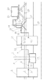
Fig. 1 is structural representation of the present invention.
In accompanying drawing, parts are numbered: 1 is the low-water level control tube, and 2 are the expection low-water level, and 3,12 and 14 is filter screen, and 4,9,15 and 19 is conduit, 5,10,16 and 21 is water control valve, and 6 is wireway, and 7 is drinking-water pipe, 8 is remaining water collection tank, and 11 is the high water stage control tube, and 13 are the expection high water stage, 17 is the bottom rubber plug, and 18 is water supply bottle, and 20 is the bottleneck rubber plug, 22 and 25 is support, and 23 is supply tank, and 24 is water filling port, 26 is earth's surface waterflooding layer, and 27 is peat bed, and 28 is clay layer.
Embodiment
When the present invention specifically implements, in advance at the on-the-spot same class vegetation region of selecting to be in same waterflooding layer of Marsh Wetland field test, cut out the cut channel identical with high water stage control tube 11 internal diameters with low-water level control tube 1 with stainless steel knife, cut channel penetrates peat bed 27, and gos deep into clay layer 28.Low-water level control tube 1 and high water stage control tube 11 are inserted soil along cut channel, until the following 20cm of clay layer 28 is goed deep in its lower end.Low-water level control tube 1 and the 11 upper end exposures of high water stage control tube are in earth's surface waterflooding layer 26.According to the expection low-water level 2 that will realize, 1 wall one side expection low-water level 2 places, position open an aperture at the low-water level control tube, conduit 4 one ends are passed this aperture extend in low-water level control tube 1, the end that conduit 4 is positioned at low-water level control tube 1 is equipped with filter screen 3, on conduit 4, water control valve is housed.The top of the other end of conduit 4 being passed remaining water collection tank 8 extend in remaining water collection tank 8.In order to collect to greatest extent the remaining water from low-water level control tube 1, the length that conduit 4 is positioned at remaining water collection tank 8 is that 2cm gets final product.In order to make the remaining water in low-water level control tube 1 can automatically flow into remaining water collection tank 8 under Action of Gravity Field, remaining water collection tank 8 bottoms to be inserted in clay layer 28, top is positioned at peat bed 27, keeps the position of remaining water collection tank 8 lower than expection low-water level 2.In order to make remaining water collection tank 8 inner and outer air pressures consistent, keep remaining water to collect unobstructed, at remaining water collection tank 8 tops, wireway 6 is installed.Wireway 6 one ends pass remaining water collection tank 8 tops and extend in remaining water collection tank 8, and the length that wireway 6 is positioned at remaining water collection tank 8 is that 2cm gets final product, and other end exposure is in earth's surface waterflooding layer 26.In order regularly to extract the ponding in remaining water collection tank 8 out, extract its volume out to prevent the ponding in remaining water collection tank 8, cause Yu Shui to reflux, at remaining water collection tank 8 tops, drinking-water pipe 7 is installed.Drinking-water pipe 7 one ends pass remaining water collection tank 8 tops and extend in remaining water collection tank 8, and drinking-water pipe 7 stretches into an end of leading in remaining water collection tank 8 and is positioned at remaining water collection tank 8 bottoms, and other end exposure is in earth's surface waterflooding layer 26.High water stage control tube 11 tube wall one side expection high water stage 13 places, position open an aperture, one end of conduit 9 is passed this aperture to be extend in high water stage control tube 11, the end that conduit 9 stretches into high water stage control tube 11 tube walls is equipped with filter screen 12, water control valve 10 is installed on conduit 9, and the other end of conduit 9 passes remaining water collection tank 8 tops and extend in remaining water collection tank 8.High water stage control tube 11 tube wall opposite side expection low-water level 2 places, position open an aperture, one end of conduit 15 passes this aperture and extend in high water stage control tube 11, the end that conduit 15 stretches into high water stage control tube 11 tube walls is equipped with filter screen 14, water control valve 16 is installed on conduit 15, and the bottom rubber plug 17 that the other end of conduit 15 passes water supply bottle 18 1 sides extend in water supply bottle 18.
After completing above-mentioned each parts connection, encapsulation process is all done in low-water level control tube 1, remaining water collection tank 8, high water stage control tube 11, water supply bottle 18 and supply tank 23 and conduit 4,9,15 and 19 junction, and simultaneously remaining water collection tank 8 is also done same encapsulation process with the junction of wireway 6 and drinking-water pipe 7.
When adopting apparatus of the present invention to carry out the wetland water level while automatically controlling, fill with water in advance in supply tank 23, the bottom rubber plug 17 of jam-pack water supply bottle 18, fill with water in water supply bottle 18, jam-pack bottleneck rubber plug 20.Then, open the water control valve 5,10,16 and 21 on conduit 4,9,15 and 19, this device starts operation automatically.Need only and regularly by water filling port 24, add water in supply tank 23 in operational process, and by drinking-water pipe 7, take out the interior water of remaining water collection tank 8, can realize the water levels in low-water level control tube 1 and high water stage control tube 11 are controlled automatically.
Claims (1)
1. device of automatically controlling the Marsh Wetland water level without the additionaling power original position, it is characterized in that: this device comprises the low-water level control tube, remaining water collection tank, the high water stage control tube, water supply bottle, supply tank, conduit, water control valve, filter screen and support, low-water level control tube both ends open, the clay layer of Marsh Wetland is inserted in low-water level control tube lower end, Marsh Wetland earth's surface waterflooding layer is exposed in the upper end of low-water level control tube, low-water level control tube tube wall one place, side expection low-water level position opens an aperture, one end of conduit passes this aperture and extend in the low-water level control tube, the end that conduit stretches into low-water level control tube tube wall is equipped with filter screen, water control valve is installed on conduit, the other end of conduit passes remaining water collection tank top and extend in remaining water collection tank, remaining water collection tank is seal box, and remaining water collection tank tip position is lower than the expection low-water level in the low-water level control tube, remaining water collection tank is equipped with wireway and drinking-water pipe, wireway one end passes remaining water collection tank top and extend in remaining water collection tank, and other end exposure is in earth's surface waterflooding layer, drinking-water pipe one end passes remaining water collection tank top and extend in remaining water collection tank, and drinking-water pipe stretches into an end of leading in remaining water collection tank and is positioned at remaining water collection tank bottom, and other end exposure is in earth's surface waterflooding layer, high water stage control tube both ends open, the clay layer of Marsh Wetland is inserted in high water stage control tube lower end, Marsh Wetland earth's surface waterflooding layer is exposed in the upper end of high water stage control tube, high water stage control tube tube wall one place, side expection high water stage position opens an aperture, having an end of a conduit to pass this aperture extend in the high water stage control tube, the end that this conduit stretches into high water stage control tube tube wall is equipped with filter screen, on this conduit, water control valve is installed, the other end of this conduit passes remaining water collection tank top and extend in remaining water collection tank, place, high water stage control tube tube wall opposite side expection low-water level position opens an aperture, having an end of a conduit to pass this aperture extend in the high water stage control tube, the end that this conduit stretches into high water stage control tube tube wall is equipped with filter screen, on this conduit, water control valve is installed, the bottom rubber plug that the other end of this conduit passes water supply bottle one side extend in water supply bottle, water supply bottle is positioned on support, and water supply bottle bottom rubber plug is higher than the expection high water stage, the water supply bottle bottleneck is equipped with the bottleneck rubber plug, one end of conduit passes the bottleneck rubber plug and extend in water supply bottle, the end that conduit stretches in water supply bottle is positioned at the water supply bottle bottom, and water control valve is housed on conduit, and the other end of conduit passes supply tank one side bottom and extend in supply tank, supply tank is positioned on support, and the supply tank bottom is higher than water supply bottle bottom rubber plug, and the top of supply tank has water filling port.
Priority Applications (1)
| Application Number | Priority Date | Filing Date | Title |
|---|---|---|---|
| CN2011104358801A CN102541097B (en) | 2011-12-22 | 2011-12-22 | Device for carrying out in-situ automatic control on water level of marsh wetland without external power |
Applications Claiming Priority (1)
| Application Number | Priority Date | Filing Date | Title |
|---|---|---|---|
| CN2011104358801A CN102541097B (en) | 2011-12-22 | 2011-12-22 | Device for carrying out in-situ automatic control on water level of marsh wetland without external power |
Publications (2)
| Publication Number | Publication Date |
|---|---|
| CN102541097A CN102541097A (en) | 2012-07-04 |
| CN102541097B true CN102541097B (en) | 2013-11-20 |
Family
ID=46348184
Family Applications (1)
| Application Number | Title | Priority Date | Filing Date |
|---|---|---|---|
| CN2011104358801A Expired - Fee Related CN102541097B (en) | 2011-12-22 | 2011-12-22 | Device for carrying out in-situ automatic control on water level of marsh wetland without external power |
Country Status (1)
| Country | Link |
|---|---|
| CN (1) | CN102541097B (en) |
Families Citing this family (3)
| Publication number | Priority date | Publication date | Assignee | Title |
|---|---|---|---|---|
| CN107121533A (en) * | 2017-06-13 | 2017-09-01 | 中国科学院烟台海岸带研究所 | A kind of experimental rig and its application method for simulating earth's surface SEA LEVEL VARIATION and alternation of wetting and drying |
| CN107678450A (en) * | 2017-11-08 | 2018-02-09 | 东北林业大学 | Water level auto control system |
| CN107935188B (en) * | 2017-12-09 | 2020-07-28 | 安徽星辰规划建筑设计有限公司 | Urban landscape wetland system capable of automatically controlling liquid level |
Citations (3)
| Publication number | Priority date | Publication date | Assignee | Title |
|---|---|---|---|---|
| CN2932025Y (en) * | 2005-11-30 | 2007-08-08 | 江苏科技大学 | Electrode type steam trap |
| CN201662721U (en) * | 2010-03-12 | 2010-12-01 | 中国电力工程顾问集团华北电力设计院工程有限公司 | Automatic water level controller |
| CN202016899U (en) * | 2011-04-11 | 2011-10-26 | 黄河勘测规划设计有限公司 | Water level regulator for constructed wetland |
Family Cites Families (2)
| Publication number | Priority date | Publication date | Assignee | Title |
|---|---|---|---|---|
| JPH1018369A (en) * | 1996-07-04 | 1998-01-20 | Shigeko Kohiyama | Water storage device and supply water control unit attached to the water storage device |
| KR100985209B1 (en) * | 2009-11-03 | 2010-10-05 | 서흥이엔지 주식회사 | Wireless automatic water-level controlling apparatus |
-
2011
- 2011-12-22 CN CN2011104358801A patent/CN102541097B/en not_active Expired - Fee Related
Patent Citations (3)
| Publication number | Priority date | Publication date | Assignee | Title |
|---|---|---|---|---|
| CN2932025Y (en) * | 2005-11-30 | 2007-08-08 | 江苏科技大学 | Electrode type steam trap |
| CN201662721U (en) * | 2010-03-12 | 2010-12-01 | 中国电力工程顾问集团华北电力设计院工程有限公司 | Automatic water level controller |
| CN202016899U (en) * | 2011-04-11 | 2011-10-26 | 黄河勘测规划设计有限公司 | Water level regulator for constructed wetland |
Non-Patent Citations (1)
| Title |
|---|
| JP特开平10-18369A 1998.01.20 |
Also Published As
| Publication number | Publication date |
|---|---|
| CN102541097A (en) | 2012-07-04 |
Similar Documents
| Publication | Publication Date | Title |
|---|---|---|
| CN101556269B (en) | Trough for simulating groundwater pollution | |
| CN106370804B (en) | A kind of sampling method of the three-dimensional visible simulator of contaminant transportation conversion | |
| CN204116337U (en) | A kind of native fish device of contaminant transportation simulation | |
| CN103046528B (en) | A kind of well casing for underground water in the vertical efficient decimation low-permeability water-bearing medium of laboratory and using method | |
| CN103529190B (en) | Aeration and vapor extraction combination two-dimensional testing device | |
| CN103630659A (en) | Simulation test device and simulation test method for in-situ chemical and biological remediation of underground water | |
| CN103336100B (en) | Groundwater contamination process and pollution amelioration integration analogue means and method | |
| CN110681685A (en) | Polluted site soil-underground water integrated simulation restoration device and method | |
| CN103728435A (en) | Slope simulation test device and test method under coupling effects of rainfall and underground water | |
| CN102520131A (en) | Multi-layered aquifer underground flow system-based underground water pollution simulator | |
| CN204116335U (en) | Soil pollutant Transport And Transformation analogue experiment installation | |
| CN102541097B (en) | Device for carrying out in-situ automatic control on water level of marsh wetland without external power | |
| CN202929029U (en) | Simulation test device for in-situ chemical and biological remediation of underground water | |
| CN210995782U (en) | Contaminated site soil-groundwater integral type simulation prosthetic devices | |
| CN101736716B (en) | Large-sized earth pillar series connection simulator for soil solute transport | |
| CN105547966A (en) | Aeration zone and saturated zone percolation experiment device under control of intermittent river | |
| CN106781962B (en) | A kind of heterogeneous isotropic aquifer seepage action of ground water rule simulation test device | |
| CN206223767U (en) | Three-dimensional visible analogue means of the pollutant in the heterogeneous Migration In Aquifer conversion of saturation in a kind of simulation underground environment | |
| CN205538581U (en) | Package band of gas and zone of saturation seepage flow experimental apparatus under river control of intermittent type nature | |
| CN203324268U (en) | Earth pillar infiltration and leaching simulator | |
| CN113029869A (en) | Three-dimensional visual simulation analysis device for pollutant leaching during backfilling of renewable solid material | |
| CN101800000A (en) | Natural gas exploitation simulator of multi-angle horizontal branch well | |
| CN206532507U (en) | A kind of heterogeneous isotropic aquifer seepage action of ground water rule simulation testing instrument | |
| CN210243647U (en) | Soil column leaching device for downward infiltration and migration of pollutants | |
| CN201335829Y (en) | Device for observing obstruction caused to seepage of groundwater by microorganisms |
Legal Events
| Date | Code | Title | Description |
|---|---|---|---|
| C06 | Publication | ||
| PB01 | Publication | ||
| C10 | Entry into substantive examination | ||
| SE01 | Entry into force of request for substantive examination | ||
| C14 | Grant of patent or utility model | ||
| GR01 | Patent grant | ||
| CF01 | Termination of patent right due to non-payment of annual fee |
Granted publication date: 20131120 Termination date: 20141222 |
|
| EXPY | Termination of patent right or utility model |