CN102528600A - Burr removal device - Google Patents
Burr removal device Download PDFInfo
- Publication number
- CN102528600A CN102528600A CN2010106116111A CN201010611611A CN102528600A CN 102528600 A CN102528600 A CN 102528600A CN 2010106116111 A CN2010106116111 A CN 2010106116111A CN 201010611611 A CN201010611611 A CN 201010611611A CN 102528600 A CN102528600 A CN 102528600A
- Authority
- CN
- China
- Prior art keywords
- motor
- burr
- rotor
- removal device
- brush
- Prior art date
- Legal status (The legal status is an assumption and is not a legal conclusion. Google has not performed a legal analysis and makes no representation as to the accuracy of the status listed.)
- Granted
Links
Images


Landscapes
- Finish Polishing, Edge Sharpening, And Grinding By Specific Grinding Devices (AREA)
- Polishing Bodies And Polishing Tools (AREA)
- Grinding And Polishing Of Tertiary Curved Surfaces And Surfaces With Complex Shapes (AREA)
Abstract
本发明公开了一种毛刺去除装置,其包括:机床主体,用于固定转子型线,且所述机床主体上设置有中托板,该转子包括一个以上的转子型线;设置于所述机床主体的中托板上的第一电机;该第一电机的电机轴连接有第一毛刺刷;所述第一毛刺刷接触所述转子型线的一端面;以及机床主体内部设置有传动装置,所述传动装置能带动所述转子型线纵向自转,和所述第一电机带动所述第一毛刺刷横向自转,以去除所述转子型线端面的毛刺。该毛刺去除装置的结构简单,其能够快速有效地去除转子型线端面的毛刺,使得转子型线端面均匀一致。
The invention discloses a burr removal device, which comprises: a machine tool main body for fixing a rotor profile, and a middle supporting plate is arranged on the machine tool main body, and the rotor includes more than one rotor profile; The first motor on the middle supporting plate of the main body; the motor shaft of the first motor is connected with a first burr brush; the first burr brush contacts an end surface of the rotor profile; and a transmission device is arranged inside the machine tool body, The transmission device can drive the rotor profile to rotate longitudinally, and the first motor can drive the first burr brush to rotate laterally, so as to remove the burrs on the end surface of the rotor profile. The burr removing device has a simple structure, and can quickly and effectively remove the burrs on the end surface of the rotor profile, so that the end surface of the rotor profile is uniform.
Description
技术领域 technical field
本发明涉及机械加工领域,尤其涉及一种毛刺去除装置。The invention relates to the field of mechanical processing, in particular to a burr removal device.
背景技术 Background technique
参照图1所示,图1A示出了现有技术中的一种阳转子型线的端面结构示意图;图1B示出了现有技术中的一种阴转子型线的端面结构示意图。其中,阴转子型线和阳转子型线相互啮合组成螺杆压缩机的核心结构,且包含阴转子型线和阳转子型线的转子型线对螺杆压缩机的噪声和性能具有决定性的影响。通常制备的转子型线的端面存在较多的毛刺,如图1A中的阴转子型线包括阴转子型线本体1和毛刺2,图1B中的阳转子型线包括阳转子型线本体3和毛刺2。在实际压缩机使用的转子型线需要去除转子型线端面的毛刺,以便降低压缩机的噪声和性能。Referring to FIG. 1 , FIG. 1A shows a schematic view of the end surface structure of a male rotor profile in the prior art; FIG. 1B shows a schematic view of the end surface structure of a female rotor profile in the prior art. Among them, the core structure of the screw compressor is formed by the meshing of the female rotor profile and the male rotor profile, and the rotor profile including the female rotor profile and the male rotor profile has a decisive impact on the noise and performance of the screw compressor. Generally, there are many burrs on the end surface of the prepared rotor profile, as shown in Figure 1A, the female rotor profile includes the female rotor profile body 1 and
目前,去除转子型线端面的毛刺只能是人工操作,即作业人员采用钢丝刷或砂轮打磨毛刺进行毛刺的磨削或人工通过砂轮机按照型线出刀后的形状进行磨削。该方法的生产效率低,劳动强度大,且去除不干净。进一步地,采用砂轮机进行磨削时,容易出现较多的废品,如转子型线端面被磨削较多,进而不符合实际要求。故,如何设计一种较好的去除转子型线端面毛刺的装置成为当前需要解决的技术问题。At present, removing the burr on the end face of the rotor profile can only be done manually, that is, the operator uses a wire brush or a grinding wheel to grind the burr to grind the burr, or manually grinds the burr according to the shape of the profile after the knife is drawn by a grinder. The production efficiency of this method is low, and labor intensity is big, and removes not clean. Furthermore, when using a grinder for grinding, it is easy to produce more waste products, such as the end face of the rotor profile is ground more, which does not meet the actual requirements. Therefore, how to design a better device for removing the burrs on the end surface of the rotor profile has become a technical problem that needs to be solved at present.
发明内容 Contents of the invention
本发明提供一种毛刺去除装置,该毛刺去除装置能够快速有效地去除转子型线端面的毛刺,且能降低作业人员的劳动强度,同时提高了生产效率。The invention provides a burr removing device, which can quickly and effectively remove the burrs on the end face of the rotor profile, reduce the labor intensity of operators, and improve production efficiency at the same time.
本发明提供的毛刺去除装置,包括:The deburring device provided by the present invention includes:
机床主体,用于固定转子,且所述机床主体上设置有中托板,该转子包括一个以上的转子型线;The main body of the machine tool is used to fix the rotor, and the main body of the machine tool is provided with a middle supporting plate, and the rotor includes more than one rotor profile;
设置于所述机床主体的中托板上的第一电机;该第一电机的电机轴连接有第一毛刺刷;The first motor arranged on the middle pallet of the machine tool body; the motor shaft of the first motor is connected with a first burr brush;
所述第一毛刺刷接触所述转子型线的一端面;以及the first burr brush contacts an end face of the rotor profile; and
机床主体内部设置有传动装置,所述传动装置能带动所述转子型线纵向自转,和所述第一电机带动所述第一毛刺刷横向自转,以去除所述转子型线端面的毛刺。A transmission device is arranged inside the main body of the machine tool, the transmission device can drive the rotor profile to rotate longitudinally, and the first motor drives the first burr brush to rotate horizontally to remove burrs from the end surface of the rotor profile.
本发明的毛刺去除装置,该毛刺去除装置的结构简单,其能够快速有效地去除转子型线端面的毛刺,使得转子型线端面均匀一致,有效避免了现有技术中废品的出现。进一步降低了作业人员的劳动强度,以及提高了生产效率。The deburring device of the present invention has a simple structure, and can quickly and effectively remove the burrs on the end surface of the rotor profile, making the end surface of the rotor profile uniform, effectively avoiding the occurrence of waste products in the prior art. The labor intensity of the operators is further reduced, and the production efficiency is improved.
附图说明 Description of drawings
为了更清楚地说明本发明或现有技术中的技术方案,下面将对实施例或现有技术描述中所需要使用的附图作一简单地介绍,显而易见地,下面描述中的附图是本发明的一些实施例,对于本领域普通技术人员来讲,在不付出创造性劳动的前提下,还可以根据这些附图获得其他的附图。In order to more clearly illustrate the present invention or the technical solutions in the prior art, the accompanying drawings that need to be used in the description of the embodiments or the prior art will be briefly introduced below. Obviously, the accompanying drawings in the following description are the present invention. For some embodiments of the invention, those skilled in the art can also obtain other drawings based on these drawings without creative effort.
图1A为现有技术中的一种阳转子型线的端面结构示意图;Fig. 1A is a schematic view of the end face structure of a male rotor profile in the prior art;
图1B为现有技术中的一种阴转子型线的端面结构示意图;Fig. 1B is a schematic view of the end face structure of a female rotor profile in the prior art;
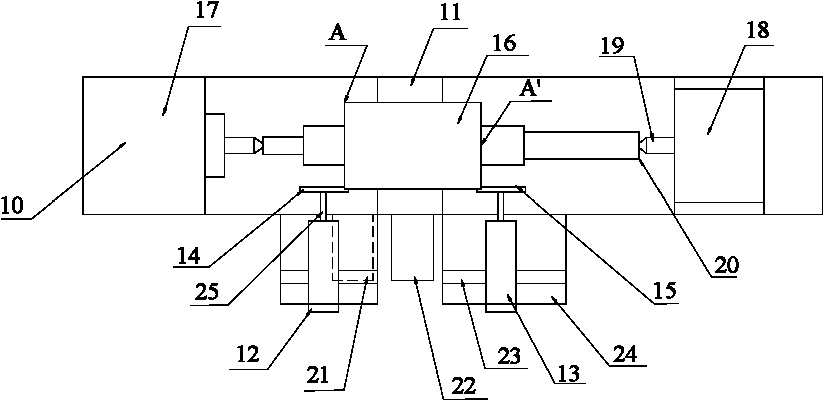
图2为本发明的毛刺去除装置实施例的结构示意图;Fig. 2 is a schematic structural view of an embodiment of a deburring device of the present invention;
图3A为本发明的去除毛刺后的阳转子型线端面的示意图;Fig. 3A is a schematic diagram of the end face of the male rotor profile after deburring according to the present invention;
图3B为本发明的去除毛刺后的阴转子型线端面的示意图。Fig. 3B is a schematic diagram of the end face of the female rotor after deburring according to the present invention.
具体实施方式 Detailed ways
为使本发明的目的、技术方案和优点更加清楚,下面将结合本发明实施例中的附图,对本发明实施例中的技术方案进行清楚、完整地描述,显然,所描述的实施例是本发明一部分实施例,而不是全部的实施例。基于本发明中的实施例,本领域普通技术人员在没有作出创造性劳动前提下所获得的所有其他实施例,都属于本发明保护的范围。In order to make the purpose, technical solutions and advantages of the present invention clearer, the technical solutions in the embodiments of the present invention will be clearly and completely described below in conjunction with the accompanying drawings in the embodiments of the present invention. Obviously, the described embodiments are the Some, but not all, embodiments are invented. Based on the embodiments of the present invention, all other embodiments obtained by persons of ordinary skill in the art without creative efforts fall within the protection scope of the present invention.
以下提及的横向是指机床主体的轴向方向,即机床主体的床头和尾座相连接的连线的方向,纵向为垂直机床主体轴向的方向,即以下提及的第一电机/第二电机的轴向。The horizontal direction mentioned below refers to the axial direction of the main body of the machine tool, that is, the direction of the line connecting the headstock and the tailstock of the main body of the machine tool, and the longitudinal direction refers to the direction perpendicular to the axial direction of the main body of the machine tool, that is, the first motor/motor mentioned below The axis of the second motor.
第一实施例first embodiment
本实施例中的毛刺去除装置,包括:用于固定转子的机床主体、第一电机和第一毛刺刷。以下提及的转子可包括一个以上的转子型线,通常是一个转子对应一个转子型线,该转子型线具有两个转子型线端面,另外,下面所述的用于固定转子型线的机床主体即为用于固定转子型线的机床主体。其中,用于固定转子的机床主体包括,承接第一电机的中托板和机床主体内部的传动装置。即机床主体的中托板上设置有第一电机,该第一电机的电机轴端部固定连接有第一毛刺刷,在使用中第一毛刺刷需要接触转子型线的端面,且机床主体内部设置的传动装置能带动所述转子型线纵向自转,以及第一电机带动第一毛刺刷横向自转,进而第一毛刺刷能够去除转子型线端面的毛刺。The deburring device in this embodiment includes: a machine tool body for fixing the rotor, a first motor and a first burr brush. The rotor mentioned below may include more than one rotor profile, usually one rotor corresponds to one rotor profile, and the rotor profile has two rotor profile end surfaces. In addition, the machine tool for fixing the rotor profile described below The main body is the main body of the machine tool used to fix the profile of the rotor. Wherein, the main body of the machine tool for fixing the rotor includes a middle supporting plate for receiving the first motor and a transmission device inside the main body of the machine tool. That is to say, a first motor is arranged on the middle pallet of the machine tool body, and a first burr brush is fixedly connected to the end of the motor shaft of the first motor. In use, the first burr brush needs to contact the end face of the rotor profile, and The provided transmission device can drive the rotor profile to rotate longitudinally, and the first motor drives the first burr brush to rotate laterally, and then the first burr brush can remove burrs from the end surface of the rotor profile.
通常,第一毛刺刷与第一电机的电机轴之间采用连接件连接,该连接件的一端为带有键槽的内孔结构并固定于所述第一电机的电机轴,另一端为带螺纹的阶梯轴用于固定所述第一毛刺刷。在使用时,机床主体内部的传动装置带动所述转子的转子型线纵向自转即纵向转动,和所述第一电机带动所述第一毛刺刷横向自转即横向转动,以较好去除所述转子型线端面的毛刺。需要说明的是,去除某一转子型线的时间和速度是有作业人员进行设定的,可有效控制第一毛刺刷的速度和时间,以便较好去除转子型线端面的毛刺,且不损坏转子型线的端面。Usually, the first burr brush and the motor shaft of the first motor are connected by a connecting piece. One end of the connecting piece is an inner hole structure with a keyway and is fixed on the motor shaft of the first motor, and the other end is a threaded A stepped shaft is used to fix the first burr brush. When in use, the transmission device inside the main body of the machine tool drives the rotor profile of the rotor to rotate longitudinally, that is, to rotate longitudinally, and the first motor drives the first burr brush to rotate horizontally, that is, to rotate horizontally, so as to better remove the Burrs on the end face of the molded line. It should be noted that the time and speed of removing a certain rotor profile are set by the operator, and the speed and time of the first burr brush can be effectively controlled so as to better remove the burrs on the end surface of the rotor profile without damaging The end face of the rotor profile.
优选地,毛刺去除装置还可包括:调节手轮,其固定于机床主体的中托板上,用于调节所述第一电机的纵向位移和横向位移,以便使用过程中的第一毛刺刷与转子型线的端面能够接触。特别地,调节手轮可包括纵向调节手轮和横向调节手轮,该纵向调节手轮用于调节第一电机的纵向位移,横向调节手轮用于调节第一电机的横向位移,该纵向调节手轮和横向调节手轮分别独立设置在所述中托板上。优选地,所述中托板上设置有滑道,该滑道可为纵向滑道或横向滑道,为使调节第一电机的横向或纵向位移方便,可将第一电机设置在机床主体的中托板表面的滑道上。Preferably, the burr removal device may further include: an adjusting hand wheel, which is fixed on the middle support plate of the machine tool body, and is used to adjust the longitudinal displacement and lateral displacement of the first motor, so that the first burr brush and The end faces of the rotor profiles are able to touch. In particular, the adjustment handwheel may include a longitudinal adjustment handwheel and a lateral adjustment handwheel, the longitudinal adjustment handwheel is used to adjust the longitudinal displacement of the first motor, the lateral adjustment handwheel is used to adjust the lateral displacement of the first motor, and the longitudinal adjustment The handwheel and the lateral adjustment handwheel are independently arranged on the middle support plate. Preferably, a slideway is provided on the middle pallet, and the slideway can be a longitudinal slideway or a horizontal slideway. In order to facilitate the adjustment of the lateral or longitudinal displacement of the first motor, the first motor can be arranged on the main body of the machine tool. on the slideway on the surface of the middle pallet.
进一步地,毛刺去除装置还包括:设置于所述机床主体的中托板上的第二电机,该第二电机平行于第一电机;以及第二电机的电机轴固定连接有第二毛刺刷,在使用中,第二毛刺刷接触转子型线的另一端面。现有的任意转子型线均包括两个端面,故本实施例中设置第一毛刺刷和第二毛刺刷,能够提高毛刺去除装置的生产效率。本实施例中的第二毛刺刷与所述第二电机的电机轴之间通过连接件连接,该连接件的一端为带有键槽的内孔结构并固定于所述第二电机的电机轴,另一端为带螺纹的阶梯轴用于固定所述第二毛刺刷;进而第二电机能够带动第二毛刺刷进行运转。Further, the burr removal device further includes: a second motor arranged on the middle pallet of the machine tool body, the second motor is parallel to the first motor; and the motor shaft of the second motor is fixedly connected with a second burr brush, In use, the second burr brush contacts the other end face of the rotor profile. Any existing rotor profile includes two end faces, so the first burr brush and the second burr brush are provided in this embodiment, which can improve the production efficiency of the burr removal device. The second burr brush in this embodiment is connected to the motor shaft of the second motor through a connecting piece, one end of the connecting piece is an inner hole structure with a keyway and is fixed to the motor shaft of the second motor, The other end is a threaded stepped shaft for fixing the second burr brush; furthermore, the second motor can drive the second burr brush to run.
实际中,横向调节手轮可同时调节第一电机和第二电机的横向距离,纵向调节手轮可同时调节第一电机和和第二电机的纵向位移。当然,也可以设置两个横向调节手轮和两个纵向调节手轮,其分别调节可设于中托板滑道上的第一电机和第二电机。另外,上述机床主体还可能包括各种机床自身部件,其调节手轮也可以通过相对应的机床自身部件将其固定,只要能够实现调节第一电机和/或第二电机即可,本实施例中不限定该处的结构部件和连接关系。另外,本实施例中的第一电机和所述第二电机之间的距离可为160mm至500mm。In practice, the horizontal adjustment handwheel can simultaneously adjust the lateral distance between the first motor and the second motor, and the longitudinal adjustment handwheel can simultaneously adjust the longitudinal displacement of the first motor and the second motor. Of course, two horizontal adjustment handwheels and two longitudinal adjustment handwheels can also be set, which respectively adjust the first motor and the second motor which can be arranged on the slideway of the middle pallet. In addition, the above-mentioned machine tool body may also include various parts of the machine tool itself, and its adjustment handwheel may also be fixed by the corresponding parts of the machine tool itself, as long as the first motor and/or the second motor can be adjusted. The structural components and connection relationship here are not limited. In addition, the distance between the first motor and the second motor in this embodiment may be 160mm to 500mm.
需要说明的是,上述的第一毛刺刷和第二毛刺刷均为含有磨粒的抛光毛刺刷,进而可较好的去除转子型线端面的毛刺,通常通过控制毛刺去除装置的时间达到完全去除转子型线端面毛刺的效果。特别地,本实施例中提及的转子型线包括阳转子型线和阴转子型线。该转子型线两端面之间的距离可为452mm至195mm。It should be noted that the first burr brush and the second burr brush mentioned above are both polishing burr brushes containing abrasive particles, which can better remove the burrs on the end surface of the rotor profile, usually by controlling the time of the burr removal device to achieve complete removal The effect of burrs on the end face of the rotor profile. In particular, the rotor profile mentioned in this embodiment includes a male rotor profile and a female rotor profile. The distance between the two ends of the rotor profile can be 452mm to 195mm.
第二实施例second embodiment
参照图2所示,图2示出了本发明的毛刺去除装置实施例的结构示意图;该毛刺去除装置包括:机床主体10,设置在机床主体10的中托板11上的第一电机12和第二电机13,第一电机12固定连接第一毛刺刷14,第二电机13固定连接第二毛刺刷15,该第一毛刺刷14和第二毛刺刷15分别接触转子型线16的两个端面(如图2中的端面A和端面A’)。With reference to shown in Fig. 2, Fig. 2 shows the structural representation of the deburring device embodiment of the present invention; The
其中,机床主体包括床头17、尾座18、位于床头17和尾座18之间的中托板11。床头17、尾座18相对面上分别设有顶尖19,以及床头17和尾座18内部分别设有传动装置(图中未示出),该传动装置分别固定连接各自的顶尖19,并带动顶尖19一起转动,也就是说,机床主体10上还设置有两个相对的顶尖19,每一顶尖19与转子型线16的阶梯轴20连接/支撑,以将转子固定于两个顶尖19之间。以下提及的转子可为具有阶梯轴的转子型线16,该转子型线16具有两个转子型线端面。本实施例中的转子型线16的阶梯轴的两端分别和床头17、尾座18的顶尖19支撑,以使床头17和尾座18内的传动装置(图中未示出)转动进而带动转子型线16纵向自转即纵向转动。上述机床主体10的顶尖19通过转子型线16的阶梯轴20的中心孔将转子型线16固定支撑。Wherein, the machine tool main body includes a
在本实施例中,第一电机12带动第一毛刺刷14横向自转、第二电机13带动第二毛刺刷15横向自转,以便第一毛刺刷14、第二毛刺刷15能够将转子型线16的两个端面(如图2中的端面A和端面A’)的毛刺去除。In this embodiment, the
优选地,为使毛刺去除装置可适用于各种长度的转子型线(该处所述的长度是指转子型线的两个端面之间的距离),在固定第一电机12和第二电机13的中托板11上还设置有用于调节第一电机12和第二电机13之间距离的横向调节手轮21,该横向调节手轮21可通过机床主体自身部件进行固定。进一步地,中托板11上设置有滑道23(图中所示为横向滑道),第一电机12和第二电机13分别位于滑道23上,进而第一电机12和第二电机13可分别设置在机床主体10的中托板11的滑道23上横向移动。也就是说,将第一电机12和第二电机13活动安装在所述机床主体的中托板的横向滑道上,以便第一电机12和第二电机13的横向位移的调节更加方便,(本实施例中未示出纵向位移的滑道,该滑道也设置在中托板11上,其便于第一电机12和第二电机13的纵向位移的调节)。通常第一电机12和第二电机13之间的横向距离依据转子型线16的两个端面之间的距离设定,一般设为160mm至500mm,如可以设为200mm、300mm、350mm或400mm等。需要说明的是,当机床主体10的中托板11的空间(纵向)不足以容纳第一电机12和第二电机13时,可以将第一电机12和第二电机13设置在中托板11的一侧,即在中托板11的一侧设置有延伸的基台24,可通过焊接一钢板实现,在该基台24上固定第一电机12和第二电机13(实际中第一电机12和第二电机13可为两个平行设置的三相异步电机)。Preferably, in order to make the deburring device applicable to rotor profiles of various lengths (the length mentioned here refers to the distance between the two end faces of the rotor profile), the
一般,将第一毛刺刷14通过连接件25连接第一电机12的电机轴,该连接件25的一端为带有键槽的内孔结构(或为内孔结构并带有键槽)并固定于电机轴,另一端为带螺纹的阶梯轴用于连接第一毛刺刷14。相应地,第二毛刺刷15与第二电机13的电机轴之间也是通过同样结构的连接件连接,该连接件的一端为带有键槽的内孔结构并固定于所述第二电机的电机轴,另一端为带螺纹的阶梯轴用于固定所述第二毛刺刷。Generally, the
另外,在毛刺去除装置中还设置有纵向调节手轮22,其用于调节第一电机12或第二电机13与转子型线16端面(端面A或端面A’)的距离,使得第一毛刺刷14或第二毛刺刷15能够较好的接触转子型线16的端面。优选地,图2所示的毛刺去除装置的中托板上设置的横向调节手轮21和纵向调节手轮22分别独立设置在中托板上。本实施例中的横向调节手轮21和/或纵向调节手轮22可同时控制和调整第一电机12、第二电机13的横向位移和纵向位移。当上述的第一电机12和第二电机13位于连机床主体10的中托板11的延伸的基台24上时,可以将横向调节手轮21和纵向调节手轮22也设置于基台24上,以便同时调节第一电机12、第二电机13。In addition, the burr removal device is also provided with a
本实施例中提及的转子型线16可为阳转子型线和阴转子型线。现有技术中存在各种齿形的转子型线,故上述毛刺去除装置通过调节横向调节手轮21和纵向调节手轮22可调节第一电机12和第二电机13,以便适应各种转子型线16的齿形结构。The
实际的去除毛刺的过程可为:将第一毛刺刷14和第二毛刺刷15分别固定于第一电机12的电机轴和第二电机13的电机轴上,以及将待去除毛刺的转子型线16固定于机床主体10的两个顶尖19之间;以保证第一毛刺刷14和第二毛刺刷15能够完全接触转子型线16的两个端面。接着,接通机床主体10内的两个传动装置的电源和第一电机12、第二电机13的电源,通过转子型线16的纵向转动即纵向自转,和第一毛刺刷14、第二毛刺刷15横向自转,以达到自动清除转子型线16端面毛刺的目的。当然,在去除过程中,可以调节纵向调节手轮22,以便第一毛刺刷14和第二毛刺刷15完全接触转子型线16端面。The actual deburring process can be: the
上述实施例中的毛刺去除装置能够将转子型线16端面的毛刺彻底清除,且不会造成转子型线16的破坏,节约了劳动力,提高了去除转子型线16端面毛刺去除的效率。The deburring device in the above embodiment can completely remove the burrs on the end surface of the
参照图3A和图3B所示,图3A示出了本发明的去除毛刺后的阳转子型线端面的示意图,图3B示出了本发明的去除毛刺后的阴转子型线端面的示意图。其转子型线16的端面显示无毛刺,进而能够较好的应用于压缩机,当应用于压缩机时,使得压缩机内部的阴转子型线和阳转子型线在连接点处光滑过渡,进而可以减少压缩机的能耗和降低噪声,以便提高采用该压缩机的整机效率。Referring to Fig. 3A and Fig. 3B, Fig. 3A shows a schematic diagram of the end surface of the male rotor profile after deburring according to the present invention, and Fig. 3B shows a schematic diagram of the profile end surface of the female rotor after deburring according to the present invention. The end face of the
最后应说明的是:以上实施例仅用以说明本发明的技术方案,而非对其限制;尽管参照前述实施例对本发明进行了详细的说明,本领域的普通技术人员应当理解:其依然可以对前述各实施例所记载的技术方案进行修改,或者对其中部分技术特征进行等同替换;而这些修改或者替换,并不使相应技术方案。Finally, it should be noted that: the above embodiments are only used to illustrate the technical solutions of the present invention, rather than to limit them; although the present invention has been described in detail with reference to the foregoing embodiments, those of ordinary skill in the art should understand that: it can still be Modifications are made to the technical solutions described in the foregoing embodiments, or equivalent replacements are made to some of the technical features; these modifications or replacements do not constitute the corresponding technical solutions.
Claims (10)
Priority Applications (1)
| Application Number | Priority Date | Filing Date | Title |
|---|---|---|---|
| CN201010611611.1A CN102528600B (en) | 2010-12-28 | 2010-12-28 | Burr removal device |
Applications Claiming Priority (1)
| Application Number | Priority Date | Filing Date | Title |
|---|---|---|---|
| CN201010611611.1A CN102528600B (en) | 2010-12-28 | 2010-12-28 | Burr removal device |
Publications (2)
| Publication Number | Publication Date |
|---|---|
| CN102528600A true CN102528600A (en) | 2012-07-04 |
| CN102528600B CN102528600B (en) | 2015-02-04 |
Family
ID=46337290
Family Applications (1)
| Application Number | Title | Priority Date | Filing Date |
|---|---|---|---|
| CN201010611611.1A Expired - Fee Related CN102528600B (en) | 2010-12-28 | 2010-12-28 | Burr removal device |
Country Status (1)
| Country | Link |
|---|---|
| CN (1) | CN102528600B (en) |
Cited By (2)
| Publication number | Priority date | Publication date | Assignee | Title |
|---|---|---|---|---|
| CN105415126A (en) * | 2015-12-02 | 2016-03-23 | 浙江德福精密驱动制造有限公司 | External spline burr removing device |
| CN105666266A (en) * | 2016-01-30 | 2016-06-15 | 宁波中大力德智能传动股份有限公司 | Gear bearing position grinding device |
Families Citing this family (1)
| Publication number | Priority date | Publication date | Assignee | Title |
|---|---|---|---|---|
| CN107877287A (en) * | 2017-11-11 | 2018-04-06 | 成都海逸机电设备有限公司 | A kind of steel pipe burr removal device |
Citations (6)
| Publication number | Priority date | Publication date | Assignee | Title |
|---|---|---|---|---|
| US5600861A (en) * | 1993-12-15 | 1997-02-11 | Yamaha Hatsudoki Kabushiki Kaisha | Casting finishing apparatus |
| CN1312746A (en) * | 1998-08-11 | 2001-09-12 | 埃尔温·容克尔机械制造有限公司 | Grinding machines with cold turning attachments |
| CN2748218Y (en) * | 2004-01-08 | 2005-12-28 | 牡丹江乾丰轻化机械有限公司 | Knife sharpener |
| CN1995757A (en) * | 2006-01-04 | 2007-07-11 | 高举成 | Rotary type displacement compressor |
| CN201565673U (en) * | 2009-11-23 | 2010-09-01 | 浙江松菱电气有限公司 | Deburring device of rotor surface deburring machine |
| CN202028992U (en) * | 2010-12-28 | 2011-11-09 | 北京南口轨道交通机械有限责任公司 | Burr removing device |
-
2010
- 2010-12-28 CN CN201010611611.1A patent/CN102528600B/en not_active Expired - Fee Related
Patent Citations (6)
| Publication number | Priority date | Publication date | Assignee | Title |
|---|---|---|---|---|
| US5600861A (en) * | 1993-12-15 | 1997-02-11 | Yamaha Hatsudoki Kabushiki Kaisha | Casting finishing apparatus |
| CN1312746A (en) * | 1998-08-11 | 2001-09-12 | 埃尔温·容克尔机械制造有限公司 | Grinding machines with cold turning attachments |
| CN2748218Y (en) * | 2004-01-08 | 2005-12-28 | 牡丹江乾丰轻化机械有限公司 | Knife sharpener |
| CN1995757A (en) * | 2006-01-04 | 2007-07-11 | 高举成 | Rotary type displacement compressor |
| CN201565673U (en) * | 2009-11-23 | 2010-09-01 | 浙江松菱电气有限公司 | Deburring device of rotor surface deburring machine |
| CN202028992U (en) * | 2010-12-28 | 2011-11-09 | 北京南口轨道交通机械有限责任公司 | Burr removing device |
Cited By (2)
| Publication number | Priority date | Publication date | Assignee | Title |
|---|---|---|---|---|
| CN105415126A (en) * | 2015-12-02 | 2016-03-23 | 浙江德福精密驱动制造有限公司 | External spline burr removing device |
| CN105666266A (en) * | 2016-01-30 | 2016-06-15 | 宁波中大力德智能传动股份有限公司 | Gear bearing position grinding device |
Also Published As
| Publication number | Publication date |
|---|---|
| CN102528600B (en) | 2015-02-04 |
Similar Documents
| Publication | Publication Date | Title |
|---|---|---|
| CN203031424U (en) | Vertical type silicon block buffing device | |
| CN201950537U (en) | Casting-pipe inner wall grinding device | |
| CN202028992U (en) | Burr removing device | |
| CN111716204B (en) | A wood surface fine processing system | |
| CN102528600B (en) | Burr removal device | |
| CN106078394A (en) | A kind of Automatic-clamping five metals polisher | |
| CN106112761A (en) | A kind of sanding apparatus of machine components | |
| CN216781280U (en) | Edge burr removing device for aluminum alloy plate | |
| CN103894930B (en) | A kind of shaping and reconditioning special equipment of emery wheel | |
| CN113601285B (en) | Circular grinding machine for manufacturing blank bar by woodworking drill bit | |
| CN208528746U (en) | A kind of novel outer arc grinding machine of brake shoes | |
| CN206296782U (en) | A kind of sanding apparatus of machine components | |
| CN207757362U (en) | A kind of auto parts and components grinding device | |
| CN211103265U (en) | A grinding device for high-efficiency castings | |
| CN210307017U (en) | A device for polishing the inner surface of a pipe with a rotary slotted magnetic pole | |
| CN212192422U (en) | A gear double-end synchronous deburring device | |
| CN218050676U (en) | A grinding device for removing burrs from gears | |
| CN204450138U (en) | For the edging device of edge polisher | |
| CN206425953U (en) | A kind of high-efficiency aluminum bastinade mill apparatus | |
| CN203542299U (en) | Device for slotting and grinding saw blade | |
| CN205774084U (en) | A kind of topping machanism for glass processing | |
| CN209036164U (en) | A kind of polishing cleaning modul of haydite aerated building block cutting assembly line | |
| CN206925689U (en) | A kind of multi-faceted sanding apparatus of machine-building | |
| CN219925450U (en) | Railing polisher | |
| CN219987091U (en) | Double-end-face polishing device for gear machining |
Legal Events
| Date | Code | Title | Description |
|---|---|---|---|
| C06 | Publication | ||
| PB01 | Publication | ||
| C10 | Entry into substantive examination | ||
| SE01 | Entry into force of request for substantive examination | ||
| C14 | Grant of patent or utility model | ||
| GR01 | Patent grant | ||
| C56 | Change in the name or address of the patentee | ||
| CP03 | Change of name, title or address |
Address after: 102202 Beijing city Changping District South Town Road North South Town West No. 584 No. 585 Patentee after: CRRC BEIJING NANKOU CO.,LTD. Address before: 102202 Beijing city Changping District town of South Road North Patentee before: BEIJING NANKOU RAILWAY TRANSIT MACHINERY Co.,Ltd. |
|
| CF01 | Termination of patent right due to non-payment of annual fee |
Granted publication date: 20150204 |
|
| CF01 | Termination of patent right due to non-payment of annual fee |