CN102423587A - Pulse valve - Google Patents
Pulse valve Download PDFInfo
- Publication number
- CN102423587A CN102423587A CN2011102408454A CN201110240845A CN102423587A CN 102423587 A CN102423587 A CN 102423587A CN 2011102408454 A CN2011102408454 A CN 2011102408454A CN 201110240845 A CN201110240845 A CN 201110240845A CN 102423587 A CN102423587 A CN 102423587A
- Authority
- CN
- China
- Prior art keywords
- valve
- spool
- piston
- cylinder
- valve body
- Prior art date
- Legal status (The legal status is an assumption and is not a legal conclusion. Google has not performed a legal analysis and makes no representation as to the accuracy of the status listed.)
- Granted
Links
- 230000009471 action Effects 0.000 claims abstract description 11
- 239000012530 fluid Substances 0.000 claims abstract description 7
- 230000007246 mechanism Effects 0.000 claims abstract description 7
- 238000000034 method Methods 0.000 claims description 5
- 230000008569 process Effects 0.000 claims description 5
- 230000013011 mating Effects 0.000 claims description 4
- 239000007769 metal material Substances 0.000 claims description 4
- 238000007789 sealing Methods 0.000 abstract description 13
- 230000004044 response Effects 0.000 abstract description 6
- 238000004519 manufacturing process Methods 0.000 abstract description 5
- 230000000694 effects Effects 0.000 abstract description 3
- 230000007613 environmental effect Effects 0.000 abstract description 2
- 239000007789 gas Substances 0.000 description 20
- 229910000831 Steel Inorganic materials 0.000 description 4
- 230000008676 import Effects 0.000 description 4
- VNWKTOKETHGBQD-UHFFFAOYSA-N methane Chemical compound C VNWKTOKETHGBQD-UHFFFAOYSA-N 0.000 description 4
- 239000010959 steel Substances 0.000 description 4
- 230000032683 aging Effects 0.000 description 3
- 238000013016 damping Methods 0.000 description 3
- 238000010586 diagram Methods 0.000 description 3
- 239000000428 dust Substances 0.000 description 3
- 239000000126 substance Substances 0.000 description 3
- FGRBYDKOBBBPOI-UHFFFAOYSA-N 10,10-dioxo-2-[4-(N-phenylanilino)phenyl]thioxanthen-9-one Chemical compound O=C1c2ccccc2S(=O)(=O)c2ccc(cc12)-c1ccc(cc1)N(c1ccccc1)c1ccccc1 FGRBYDKOBBBPOI-UHFFFAOYSA-N 0.000 description 2
- 239000003034 coal gas Substances 0.000 description 2
- 238000005516 engineering process Methods 0.000 description 2
- 239000007788 liquid Substances 0.000 description 2
- 239000003345 natural gas Substances 0.000 description 2
- WURBVZBTWMNKQT-UHFFFAOYSA-N 1-(4-chlorophenoxy)-3,3-dimethyl-1-(1,2,4-triazol-1-yl)butan-2-one Chemical compound C1=NC=NN1C(C(=O)C(C)(C)C)OC1=CC=C(Cl)C=C1 WURBVZBTWMNKQT-UHFFFAOYSA-N 0.000 description 1
- RYGMFSIKBFXOCR-UHFFFAOYSA-N Copper Chemical compound [Cu] RYGMFSIKBFXOCR-UHFFFAOYSA-N 0.000 description 1
- 230000009286 beneficial effect Effects 0.000 description 1
- 239000004568 cement Substances 0.000 description 1
- 238000010276 construction Methods 0.000 description 1
- 229910052802 copper Inorganic materials 0.000 description 1
- 239000010949 copper Substances 0.000 description 1
- 230000007812 deficiency Effects 0.000 description 1
- 230000002950 deficient Effects 0.000 description 1
- 239000002360 explosive Substances 0.000 description 1
- 238000009434 installation Methods 0.000 description 1
- 230000033001 locomotion Effects 0.000 description 1
- 238000012423 maintenance Methods 0.000 description 1
- 239000000463 material Substances 0.000 description 1
- 239000003921 oil Substances 0.000 description 1
- 230000000505 pernicious effect Effects 0.000 description 1
- 238000003825 pressing Methods 0.000 description 1
- 239000010865 sewage Substances 0.000 description 1
- 238000013022 venting Methods 0.000 description 1
- XLYOFNOQVPJJNP-UHFFFAOYSA-N water Substances O XLYOFNOQVPJJNP-UHFFFAOYSA-N 0.000 description 1
Images


Landscapes
- Magnetically Actuated Valves (AREA)
Abstract
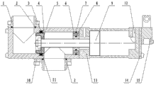
A pulse valve is characterized in that a valve body (4) and a valve core (5) of the piston valve are adopted as the valve body and the valve core, a valve core action executing mechanism is a piston cylinder, a piston rod (9) extends into the valve body (4) to serve as a core rod of the valve core (5), the valve core (5) is fixed to the telescopic end of the piston rod (9), the valve body (4) is fixedly connected with a cylinder body (13), an electromagnetic valve (15) is fixed to the cylinder body (13) or the valve body (4), and two external pipe orifices on the electromagnetic valve (15) are communicated with two fluid inlet and outlet (12) on the cylinder body (13) through a pipeline. The structure is simple, the action is reliable, the sealing effect is good, the service life is long, the environmental interference resistance is strong, the response is fast, the flow channel is shortest, the pressure drop is minimum, and the manufacturing cost is low. The volume is small, the manufacturability is good, the service life is long, and the device can be manufactured into a larger caliber, so that the device is very practical for large-flow working condition occasions.
Description
Technical field
The present invention relates to a kind of valve, relate in particular to a kind of pulse valve.Relate to the pulse valve field in the sack cleaner.
Background technology
Deashing in the sack cleaner is to adopt pulse valve that compressed air is inserted filter bag inside, will oppositely be blown in the ash bucket attached to the outside dust of filter bag.
Chinese patent notification number CN 200954422Y, on October 3 2007 day for announcing, the utility model name is called " pulse valve that a kind of pulse bag type dust collector is used "; It comprises magnetic valve, little valve gap, big valve gap; Magnetic valve is connected with little valve gap top, and the bottom of little valve gap is fixedly connected with the top of big valve gap, and the bottom of big valve gap is provided with big diaphragm; Be provided with Small diaphragm-piece between little valve gap and the big valve gap; Little valve gap inner chamber and Small diaphragm-piece form venting chambers, and big valve gap inner chamber forms lower chamber with big diaphragm, Small diaphragm-piece, and big valve gap is fixed on the outer wall of branch gas tank; Big pressing diaphragm divides an end of a typhon mouth of gas tank to withstand on the middle cover on the big diaphragm between the outer wall of big valve gap and branch gas tank.Magnetic valve is through two air chamber control impuls valves, to magnetic valve require low, not fragile, easy to maintenance.But the structure relative complex of this utility model, volume is bigger, and response speed is lower; Consumable accessory is many, and is withstand voltage and sealing property is relatively poor, and that rubber diaphragm is prone to is aging, pilot valve damping hole size is minimum; Be prone to stop up, cause the pulse valve action malfunctioning, the reliability of use and durability are still waiting to improve.
Summary of the invention
The objective of the invention is for overcome existing pulse valve rubber diaphragm be prone to aging, pilot valve damping hole size is minimum, is prone to stop up, and causes malfunctioning, the complex structure of pulse valve action; Low-response; Volume is big, and withstand voltage and defective and deficiency that sealing property is relatively poor provide a kind of simple in structure; Response is fast, the pulse valve of withstand voltage and good sealing effect.
For realizing above purpose, technical solution of the present invention is: a kind of pulse valve comprises valve body; Spool, spool action actuating mechanism and magnetic valve, described valve body and spool are the valve body and the spool of piston valve; Described spool action actuating mechanism is a piston cylinder, and piston cylinder comprises the piston rod that cylinder body is outside with stretching out cylinder body, and described piston rod stretches into the core bar of valve inner as spool; Described spool is fixed on the flexible end of piston rod; Described valve body is fixedly connected with cylinder body, and described magnetic valve is fixed on cylinder body or the valve body, and two external mouths of pipe on the magnetic valve are connected with two fluid inlet and outlets on the cylinder body through pipeline.
Described spool adopts metal material to process, and is provided with the duct of matching with spool in the described valve body.
Be provided with valve core seal ring in the described duct, the end of said spool is provided with the taper chamfering.
Described valve core seal ring is the U RunddichtringO.
Be provided with the duct of diameter less than the spool end diameter in the described valve body, the end face of said spool is provided with elaxtic seal.
Corresponding two valve ports are respectively arranged with the first valve port flange and the second valve port flange on the described valve body, and the joint face of valve body and the first valve port flange, the second valve port flange is provided with the flange seal circle.
Described flange seal circle is the O RunddichtringO.
Described valve body is socketed on the cylinder body of piston rod exposed junction, and the mating surface of valve body and cylinder body is provided with valve seals.
Described valve seals is the O RunddichtringO.
Described piston valve is piston type angle valve or straight-through valve, and piston cylinder is cylinder or hydraulic jack, and described magnetic valve is a two-position four-way solenoid valve.
Compared with prior art, beneficial effect of the present invention is:
1, the spool of piston valve adopts piston structure, the piston rod on the piston cylinder to stretch in the valve body as the core bar of piston valve core among the present invention, and spool is fixed on the piston rod.Identical with existing piston valve, also elaxtic seal can be installed on the spool, and make cartridge cover on the duct of valve body interior diameter less than spool.Spool preferably adopts metal material such as steel to process; The duct that is slidingly matched with spool is set in valve body; And valve core seal ring is set in the duct; Make the valve core seal ring interoperation in spool and the valve body, can realize inclusion seal, the piston cylinder upper piston rod stretch out and two strokes of withdrawing have determined the position and the stroke of the opening and closing of valve body inner spool.
2, the present invention is simple in structure, reliable in action, and good sealing effect, long service life, anti-environmental interference ability is strong, and response is fast, and runner is the shortest, and flow resistance is little, and pressure drop is minimum, and withstand voltage rank is high, low cost of manufacture.Control power supply of the present invention can be by PLC programme-control or the control of hand push button switch; Magnetic valve can also adopt the anti-form of exposing to the sun, to satisfy the demand of special operation condition environment, to adapt to like inflammable and explosive occasions such as coal gas, natural gas, chemical pernicious gas, liquid.
3, import and export position relation by valve port can be arranged to perpendicular type (being that import and export place-centric line is an angle of 90 degrees) and through-type (being that the import and export center line is horizontal parallel) on the valve body of the present invention; Easy for installation; The two way seal structure that matches with the duct of spool particularly; Make the import and export of valve body can exchange use, be convenient to pipe arrangement.
4, piston cylinder of the present invention can adopt cylinder or hydraulic jack, and is simple to operation when heavy caliber (being suitable for big flow) control through hydraulic pressure or pneumatic actuation, is convenient to automatic control; For the high pressure fluid, the use occasion of gas very adapts to; Do not have first guide structure, response is fast, and dynamic equilibrium is effective; With respect to the pulse valve that uses on the existing sack cleaner equipment; The present invention does not have pilot stage control, no spring, no rubber film; The runner damping hole of pulse valve pilot stage has not just had like this; It is stuck just can not valve to occur, and pilot stage is failure to actuate, the problem that main valve plug is failure to actuate, rubber film is aging.
5, among the present invention because piston adopts the hydraulic cylinder sealing structure, valve body and spool adopt steel part, so its withstand voltage rank is high, the pressure through medium can reach 31.5MPa; Can control the stroke of driving oil cylinder when driving through servo amplifier if adopt servo-cylinder (oil cylinder of band position sensor); Through setting the opening size control arbitrarily that can realize spool; And then realize flow-control through this valve; Promptly can be used for timing gearing system, realize arbitrary speed control by flow output decision; The auto-switch function of this valve also can be realized time switch control by control program, is used for automation is had the operating mode occasion of requirement.
6, volume of the present invention is little, good manufacturability, and long service life can manufacture bigger bore, and is therefore very practical to big flow operating mode occasion.Because this valve has good technology manufacturing property, make low cost of manufacture, so possessed excellent economy.Applicable media of the present invention is wider; Like air (comprising compressed air), hot-air, steam, water, oil, coal gas, natural gas, chemical liquid, gas etc.; Application is extensive, can promote the use of in industries such as environmental protection dedusting (sack cleaner), waterworks, Sewage Plant, cement plant, power plant, copper work, down-hole, chemical plant, oil plant, paper mill, pharmaceutical factory, food factories.
Description of drawings
Fig. 1 is the opening sketch map of spool 5 in first kind of structure of the present invention.
Fig. 2 is the closed condition sketch map of spool 5 in first kind of structure of the present invention.
Fig. 3 is the opening sketch map of spool 5 in second kind of structure of the present invention.
Fig. 4 is the closed condition sketch map of spool 5 in second kind of structure of the present invention.
Fig. 5 is that piston cylinder is the pneumatic schematic diagram of cylinder among the present invention.
Among the figure: the first valve port flange 1, flange seal circle 2, valve core seal ring 3, valve body 4, spool 5, sealing ring 6; Valve seals 7, sealing ring inner seal ring 8, piston 9, the second valve port flanges 10, nut 11, fluid inlet and outlet 12; Cylinder body 13, connecting plate 14, magnetic valve 15, source of the gas 16, muffler 17.
The specific embodiment
Below in conjunction with the description of drawings and the specific embodiment the present invention is done further detailed explanation.
Referring to Fig. 1-Fig. 5, a kind of pulse valve of the present invention comprises valve body; Spool, spool action actuating mechanism and magnetic valve 15, described valve body and spool are the valve body 4 and spool 5 of piston valve; Described spool action actuating mechanism is a piston cylinder, and piston cylinder comprises cylinder body 13 and the piston rod 9 that stretches out cylinder body 13 outsides, and described piston rod 9 stretches into the core bar of valve body 4 inside as spool 5; Described spool 5 is fixed on the flexible end of piston rod 9; Described valve body 4 is fixedly connected with cylinder body 13, and described magnetic valve 15 is fixed on cylinder body 13 or the valve body 4, and two external mouths of pipe on the magnetic valve 15 are connected with two fluid inlet and outlets 12 on the cylinder body 13 through pipeline.
Referring to Fig. 1 to Fig. 4, described piston valve is piston type angle valve or straight-through valve, and described valve body 4 is basic identical with the valve body and the spool of piston valve with spool 5; Fig. 1; What valve body 4 adopted among Fig. 2 is the valve body of piston straight-through valve, Fig. 3, and what valve body 4 adopted among Fig. 4 is the valve body of piston angle valve.Described spool 5 adopts metal material to process; As can adopt steel to process, the longitudinal section of spool 4 is a groove body, is provided with through hole in the bottom centre of groove body; In the through hole that piston rod 9 on the piston cylinder inserts on the groove body, with nut 11 spool 5 is fixed on the piston rod 9 again.Be provided with the duct of matching in the described valve body 4 with spool 5.Spool 5 can stretch in the duct in the valve body 4, in order to increase sealing effectiveness, preferably in described duct, is provided with valve core seal ring 3.Described valve core seal ring 3 is the U RunddichtringO, can spool 5 be sealed from the both direction that gets into or withdraw from the duct.Described valve core seal ring 3 also can adopt yx type, flower bud type or square RunddichtringO.
The another kind of closing form of spool 5 in valve body 4 is that correspondence is provided with the duct of diameter less than spool 5 end face diameters in the described valve body 4 among the present invention; The position in said duct is arranged in the stroke of spool 5 motions, and the end face of said spool 5 is provided with elaxtic seal.Described elaxtic seal can be mounted in the materials such as rubber blanket on spool 5 end faces.This form is basic identical with the end mode of piston valve core in the existing piston valve in valve body.But as the pulse valve in the sack cleaner time, the diameter in said duct can not be provided with too little, heaps near the duct to avoid dust.
Fig. 1, among Fig. 2, described valve body 4 is tightly connected through cylinder body 13 ends of sealing ring 6 with piston rod 9 one sides.Be provided with sealing ring inner seal ring 8 between the mating surface of sealing ring 6 and cylinder body 13, be provided with valve seals 7 between the contact-making surface of sealing ring 6 and valve body 4 endoporus, described valve seals 7 is the O RunddichtringO.
Fig. 3, among Fig. 4, described valve body 4 cylinder body 13 ends direct and piston rod 9 one sides are tightly connected.Described valve body 4 is socketed on the cylinder body 4 of piston rod 9 exposed junctions, and valve body 4 is provided with valve seals 7 with the mating surface of cylinder body 4, and described valve seals 7 is the O RunddichtringO.
Corresponding two valve ports are respectively arranged with the first valve port flange 1 and the second valve port flange 10 on the described valve body 4; As can adopt bolt that the first valve port flange 1 and the second valve port flange 10 are separately fixed on two valve ports of valve body 4; Can valve body 4 and the joint face of the first valve port flange 1, the second valve port flange 10 be provided with flange seal circle 2; In case heads, described flange seal circle 2 is the O RunddichtringO.
Described piston cylinder is cylinder or hydraulic jack, and described magnetic valve 15 is a two-position four-way solenoid valve, also can adopt two five-way electromagnetic valves, three position four-way electromagnetic valve.Among Fig. 1-Fig. 4, magnetic valve 15 is fixed on the connecting plate 14, and connecting plate 14 is fixed on the cylinder body 13 of piston cylinder.Also can connecting plate 14 and magnetic valve 15 be fixed on the valve body 4 of piston valve as required.
Referring to Fig. 5; When piston cylinder adopts cylinder; When magnetic valve 15 adopts two-position four-way solenoid valve; A gas port of magnetic valve 15 connects source of the gas 16, and another gas port connects gas storehouse or atmosphere through muffler 17, and in addition two external gas ports of magnetic valve 15 are connected with two fluid inlet and outlets 12 (rod chamber gas port and rodless cavity gas port) on the piston-cylinder cylinder body 13 through pipeline respectively.
Pneumatic operation principle of the present invention is following:
When magnetic valve 15 is positioned at position, a left side; Spool 5 in corresponding diagram 1 and Fig. 3 state is in opening; Source of the gas 16 leads to the rod chamber gas port of piston-cylinder through magnetic valve 15; The pressure of cylinder rod chamber is greater than the pressure of rodless cavity, and the piston rod 9 in the piston-cylinder moves to right to low order end, and the gas in the rodless cavity is arranged to atmosphere from muffler 17 through magnetic valve 15.
When magnetic valve 15 is positioned at right position; Spool 5 in corresponding diagram 2 and Fig. 4 state is in closed condition; Source of the gas 16 leads to the rodless cavity gas port of piston-cylinder through magnetic valve 15; The pressure of cylinder rodless cavity is greater than the pressure of rod chamber, and the piston rod 9 in the piston-cylinder moves to left to high order end, and the gas in the rod chamber is arranged to atmosphere from muffler 17 through magnetic valve 15.
Piston cylinder of the present invention adopts the hermetically-sealed construction of hydraulic cylinder, and valve body 4 and spool 5 adopt steel parts, so its withstand voltage rank is high, and the pressure through medium can reach 3.15MPa; Can control the stroke of driving oil cylinder when driving through servo amplifier if adopt servo-cylinder (oil cylinder of band position sensor); Through setting the opening size control arbitrarily that can realize spool 5; And then realize flow-control through piston valve; Promptly can be used for timing gearing system, realize arbitrary speed control by flow output decision; The auto-switch function of piston valve also can be realized time switch control by control program, is used for automation is had the operating mode occasion of requirement.
Claims (10)
1. pulse valve; Comprise valve body, spool, spool action actuating mechanism and magnetic valve (15); It is characterized in that: described valve body and spool are the valve body (4) and the spool (5) of piston valve; Described spool action actuating mechanism is a piston cylinder, and piston cylinder comprises cylinder body (13) and stretch out the outside piston rod (9) of cylinder body (13) that described piston rod (9) stretches into the inner core bar as spool (5) of valve body (4); Described spool (5) is fixed on the flexible end of piston rod (9); Described valve body (4) is fixedly connected with cylinder body (13), and described magnetic valve (15) is fixed on cylinder body (13) or the valve body (4), and two external mouths of pipe on the magnetic valve (15) are connected with two fluid inlet and outlets (12) on the cylinder body (13) through pipeline.
2. a kind of pulse valve according to claim 1 is characterized in that: described spool (5) adopts metal material to process, and is provided with the duct of matching with spool (5) in the described valve body (4).
3. a kind of pulse valve according to claim 2 is characterized in that: be provided with valve core seal ring (3) in the described duct, the end of said spool (5) is provided with the taper chamfering.
4. a kind of pulse valve according to claim 3 is characterized in that: described valve core seal ring (3) is the U RunddichtringO.
5. a kind of pulse valve according to claim 1 is characterized in that: be provided with the duct of diameter less than spool (5) end face diameter in the described valve body (4), the end face of said spool (5) is provided with elaxtic seal.
6. a kind of pulse valve according to claim 1; It is characterized in that: described valve body (4) is gone up corresponding two valve ports and is respectively arranged with the first valve port flange (1) and the second valve port flange (10), and the joint face of valve body (4) and the first valve port flange (1), the second valve port flange (10) is provided with flange seal circle (2).
7. a kind of pulse valve according to claim 6 is characterized in that: described flange seal circle (2) is the O RunddichtringO.
8. a kind of pulse valve according to claim 1 is characterized in that: described valve body (4) is socketed on the cylinder body (4) of piston rod (9) exposed junction, and valve body (4) is provided with valve seals (7) with the mating surface of cylinder body (4).
9. a kind of pulse valve according to claim 8 is characterized in that: described valve seals (7) is the O RunddichtringO.
10. a kind of pulse valve according to claim 1 is characterized in that: described piston valve is piston type angle valve or straight-through valve, and piston cylinder is cylinder or hydraulic jack, and described magnetic valve (15) is a two-position four-way solenoid valve.
Priority Applications (1)
| Application Number | Priority Date | Filing Date | Title |
|---|---|---|---|
| CN 201110240845 CN102423587B (en) | 2011-08-22 | 2011-08-22 | Pulse valve |
Applications Claiming Priority (1)
| Application Number | Priority Date | Filing Date | Title |
|---|---|---|---|
| CN 201110240845 CN102423587B (en) | 2011-08-22 | 2011-08-22 | Pulse valve |
Publications (2)
| Publication Number | Publication Date |
|---|---|
| CN102423587A true CN102423587A (en) | 2012-04-25 |
| CN102423587B CN102423587B (en) | 2013-12-18 |
Family
ID=45957668
Family Applications (1)
| Application Number | Title | Priority Date | Filing Date |
|---|---|---|---|
| CN 201110240845 Expired - Fee Related CN102423587B (en) | 2011-08-22 | 2011-08-22 | Pulse valve |
Country Status (1)
| Country | Link |
|---|---|
| CN (1) | CN102423587B (en) |
Cited By (1)
| Publication number | Priority date | Publication date | Assignee | Title |
|---|---|---|---|---|
| CN105156757A (en) * | 2015-08-25 | 2015-12-16 | 无锡阳工机械制造有限公司 | Mounting method for angle seat valve |
Families Citing this family (1)
| Publication number | Priority date | Publication date | Assignee | Title |
|---|---|---|---|---|
| US20250205629A1 (en) * | 2022-03-25 | 2025-06-26 | Rotex Automation Limited | Piston operated pulse jet solenoid valve |
Citations (5)
| Publication number | Priority date | Publication date | Assignee | Title |
|---|---|---|---|---|
| EP0521485A2 (en) * | 1991-07-02 | 1993-01-07 | Bang Yan Wen | Automatic control valve with isolation device between pilot and main valve |
| CN2748667Y (en) * | 2004-11-01 | 2005-12-28 | 内蒙古北方重工业集团有限公司 | Pulse type single-piston water pump device |
| CN101632887A (en) * | 2009-08-20 | 2010-01-27 | 武汉凯迪电力股份有限公司 | Combined piston type pulse solenoid valve |
| CN201505493U (en) * | 2009-08-20 | 2010-06-16 | 武汉凯迪电力股份有限公司 | Two-stage piston type pulse electromagnetic valve |
| CN202173854U (en) * | 2011-08-22 | 2012-03-28 | 张元杰 | Pulse valve |
-
2011
- 2011-08-22 CN CN 201110240845 patent/CN102423587B/en not_active Expired - Fee Related
Patent Citations (5)
| Publication number | Priority date | Publication date | Assignee | Title |
|---|---|---|---|---|
| EP0521485A2 (en) * | 1991-07-02 | 1993-01-07 | Bang Yan Wen | Automatic control valve with isolation device between pilot and main valve |
| CN2748667Y (en) * | 2004-11-01 | 2005-12-28 | 内蒙古北方重工业集团有限公司 | Pulse type single-piston water pump device |
| CN101632887A (en) * | 2009-08-20 | 2010-01-27 | 武汉凯迪电力股份有限公司 | Combined piston type pulse solenoid valve |
| CN201505493U (en) * | 2009-08-20 | 2010-06-16 | 武汉凯迪电力股份有限公司 | Two-stage piston type pulse electromagnetic valve |
| CN202173854U (en) * | 2011-08-22 | 2012-03-28 | 张元杰 | Pulse valve |
Cited By (1)
| Publication number | Priority date | Publication date | Assignee | Title |
|---|---|---|---|---|
| CN105156757A (en) * | 2015-08-25 | 2015-12-16 | 无锡阳工机械制造有限公司 | Mounting method for angle seat valve |
Also Published As
| Publication number | Publication date |
|---|---|
| CN102423587B (en) | 2013-12-18 |
Similar Documents
| Publication | Publication Date | Title |
|---|---|---|
| CN104100739A (en) | Pneumatic control combination valve and application method thereof | |
| CN201521308U (en) | High flow capacity insertion type manual direction-changing valve for hydraulic supporting frame | |
| CN203363202U (en) | Piston type stop valve | |
| CN105545858B (en) | A kind of special Pneumatic valve of pneumohydraulic pressure-cylinder and pneumohydraulic pressure-cylinder | |
| CN202173854U (en) | Pulse valve | |
| CN204004722U (en) | Balance cage type single seat regulating valve | |
| CN102423587B (en) | Pulse valve | |
| CN106907518B (en) | Double-acting pneumatic reset electric open type actuating mechanism | |
| CN202971942U (en) | Pneumatic control two-way valve | |
| CN203979505U (en) | Gas control combination brake switch and proporting | |
| CN202597861U (en) | Pile-up valve for hydraulic control of large-flow high-pressure ball valve | |
| CN202100748U (en) | Large-diameter sleeve piston hydraulic adjusting valve | |
| CN202301255U (en) | High-water-base two-position four-way electro-hydraulic reversing valve | |
| CN201310636Y (en) | Air shuttle valve | |
| CN208886047U (en) | High pressure axial flow type check valve | |
| CN111577961B (en) | Valve sealing device | |
| CN212480134U (en) | Automatic control valve for high-temperature dust-containing gas | |
| CN207297994U (en) | A kind of three beams Inlet and outlet water copper valve | |
| CN203214890U (en) | Plug-in mounting type pneumatic coaxial valve | |
| CN208535285U (en) | Double-acting spring assist type actuator | |
| CN2248274Y (en) | Self-pressing stop valve | |
| CN201065974Y (en) | Slant-positioned type oil cylinder slow-closing check valve | |
| CN222296973U (en) | Novel pneumatic pipeline stop valve | |
| CN108050297B (en) | Three-stage exhaust and waterproof hammer type air valve | |
| CN221482803U (en) | Single and double acting actuating mechanism with oil supplementing function for valve |
Legal Events
| Date | Code | Title | Description |
|---|---|---|---|
| C06 | Publication | ||
| PB01 | Publication | ||
| C10 | Entry into substantive examination | ||
| SE01 | Entry into force of request for substantive examination | ||
| C14 | Grant of patent or utility model | ||
| GR01 | Patent grant | ||
| CF01 | Termination of patent right due to non-payment of annual fee |
Granted publication date: 20131218 |
|
| CF01 | Termination of patent right due to non-payment of annual fee |