CN102392417A - Dual-cantilever bearing support structure for large steel pipe and installation method - Google Patents
Dual-cantilever bearing support structure for large steel pipe and installation method Download PDFInfo
- Publication number
- CN102392417A CN102392417A CN2011103811993A CN201110381199A CN102392417A CN 102392417 A CN102392417 A CN 102392417A CN 2011103811993 A CN2011103811993 A CN 2011103811993A CN 201110381199 A CN201110381199 A CN 201110381199A CN 102392417 A CN102392417 A CN 102392417A
- Authority
- CN
- China
- Prior art keywords
- steel pipe
- iron
- cantilever
- bridge
- big
- Prior art date
- Legal status (The legal status is an assumption and is not a legal conclusion. Google has not performed a legal analysis and makes no representation as to the accuracy of the status listed.)
- Granted
Links
Images


Abstract
Description
Claims (5)
Priority Applications (1)
| Application Number | Priority Date | Filing Date | Title |
|---|---|---|---|
| CN 201110381199 CN102392417B (en) | 2011-11-26 | 2011-11-26 | Dual-cantilever bearing support structure for large steel pipe and installation method |
Applications Claiming Priority (1)
| Application Number | Priority Date | Filing Date | Title |
|---|---|---|---|
| CN 201110381199 CN102392417B (en) | 2011-11-26 | 2011-11-26 | Dual-cantilever bearing support structure for large steel pipe and installation method |
Publications (2)
| Publication Number | Publication Date |
|---|---|
| CN102392417A true CN102392417A (en) | 2012-03-28 |
| CN102392417B CN102392417B (en) | 2013-08-21 |
Family
ID=45859789
Family Applications (1)
| Application Number | Title | Priority Date | Filing Date |
|---|---|---|---|
| CN 201110381199 Active CN102392417B (en) | 2011-11-26 | 2011-11-26 | Dual-cantilever bearing support structure for large steel pipe and installation method |
Country Status (1)
| Country | Link |
|---|---|
| CN (1) | CN102392417B (en) |
Cited By (4)
| Publication number | Priority date | Publication date | Assignee | Title |
|---|---|---|---|---|
| CN103147402A (en) * | 2013-03-27 | 2013-06-12 | 上海建工集团股份有限公司 | Support device for constructing continuous box girder bridge and elevation adjusting method |
| CN107012796A (en) * | 2017-05-25 | 2017-08-04 | 山东大学 | A kind of wide, bracket of No. zero block construction of squat pier box beam and construction method |
| CN116677203A (en) * | 2023-07-06 | 2023-09-01 | 北京住总第二开发建设有限公司 | Pipe frame structure of shaping pump and construction method thereof |
| CN116677203B (en) * | 2023-07-06 | 2024-04-16 | 北京住总第二开发建设有限公司 | Pipe frame structure of shaping pump and construction method thereof |
Citations (8)
| Publication number | Priority date | Publication date | Assignee | Title |
|---|---|---|---|---|
| JPH02406B2 (en) * | 1984-10-12 | 1990-01-08 | Nippon Kokan Kk | |
| CN1271043A (en) * | 2000-05-25 | 2000-10-25 | 徐斌 | Bridge support maintaining method and apparatus |
| JP4020406B2 (en) * | 2006-06-28 | 2007-12-12 | Jfe工建株式会社 | Formwork support mechanism and placement method |
| CN101440604A (en) * | 2008-12-29 | 2009-05-27 | 中铁大桥局股份有限公司 | Cable opposite pulling type pier-side bracket |
| CN101858055A (en) * | 2010-06-04 | 2010-10-13 | 中交第一航务工程局有限公司 | Setting steel pipe bracket support system of cover beam and construction method thereof |
| CN201762662U (en) * | 2010-08-11 | 2011-03-16 | 中铁三局集团有限公司 | Independent bridge pier capping beam formwork support |
| CN201850510U (en) * | 2010-09-30 | 2011-06-01 | 中铁四局集团第一工程有限公司 | Inverted triangular support of cast-in-situ box girder |
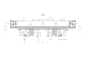
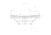
| CN202323677U (en) * | 2011-11-26 | 2012-07-11 | 科达集团股份有限公司 | Support bracket structure of double-cantilever large steel pipe |
-
2011
- 2011-11-26 CN CN 201110381199 patent/CN102392417B/en active Active
Patent Citations (8)
| Publication number | Priority date | Publication date | Assignee | Title |
|---|---|---|---|---|
| JPH02406B2 (en) * | 1984-10-12 | 1990-01-08 | Nippon Kokan Kk | |
| CN1271043A (en) * | 2000-05-25 | 2000-10-25 | 徐斌 | Bridge support maintaining method and apparatus |
| JP4020406B2 (en) * | 2006-06-28 | 2007-12-12 | Jfe工建株式会社 | Formwork support mechanism and placement method |
| CN101440604A (en) * | 2008-12-29 | 2009-05-27 | 中铁大桥局股份有限公司 | Cable opposite pulling type pier-side bracket |
| CN101858055A (en) * | 2010-06-04 | 2010-10-13 | 中交第一航务工程局有限公司 | Setting steel pipe bracket support system of cover beam and construction method thereof |
| CN201762662U (en) * | 2010-08-11 | 2011-03-16 | 中铁三局集团有限公司 | Independent bridge pier capping beam formwork support |
| CN201850510U (en) * | 2010-09-30 | 2011-06-01 | 中铁四局集团第一工程有限公司 | Inverted triangular support of cast-in-situ box girder |
| CN202323677U (en) * | 2011-11-26 | 2012-07-11 | 科达集团股份有限公司 | Support bracket structure of double-cantilever large steel pipe |
Non-Patent Citations (2)
| Title |
|---|
| 叶建伍: "浅谈桥梁仿毛勒式伸缩缝的更换施工", 《工程设计与建设》, vol. 35, no. 04, 30 July 2003 (2003-07-30), pages 20 - 22 * |
| 孟绥宝: "预应力支架在连续钢构0号块施工平台中的应用", 《铁道标准设计》, no. 06, 20 June 2009 (2009-06-20) * |
Cited By (5)
| Publication number | Priority date | Publication date | Assignee | Title |
|---|---|---|---|---|
| CN103147402A (en) * | 2013-03-27 | 2013-06-12 | 上海建工集团股份有限公司 | Support device for constructing continuous box girder bridge and elevation adjusting method |
| CN103147402B (en) * | 2013-03-27 | 2015-10-21 | 上海市政建设有限公司 | For bracing or strutting arrangement and the height regulation method of continuous box girder bridge construction |
| CN107012796A (en) * | 2017-05-25 | 2017-08-04 | 山东大学 | A kind of wide, bracket of No. zero block construction of squat pier box beam and construction method |
| CN116677203A (en) * | 2023-07-06 | 2023-09-01 | 北京住总第二开发建设有限公司 | Pipe frame structure of shaping pump and construction method thereof |
| CN116677203B (en) * | 2023-07-06 | 2024-04-16 | 北京住总第二开发建设有限公司 | Pipe frame structure of shaping pump and construction method thereof |
Also Published As
| Publication number | Publication date |
|---|---|
| CN102392417B (en) | 2013-08-21 |
Similar Documents
| Publication | Publication Date | Title |
|---|---|---|
| CN104878776A (en) | Full-automatic parking garage body structure at shallow underground layer | |
| CN109958049A (en) | A kind of modularization steel-is mixed to combine small box girder freely-supported continuous bridge and its construction method | |
| CN106381886A (en) | Partially-prefabricated assembled steel and concrete combined utility tunnel | |
| CN111851519A (en) | Space truss multilayer internal support system | |
| CN110042770A (en) | A method of using the original bridge of external prestressing steel Shu Tuokuan in length and breadth | |
| CN113882238A (en) | Large-span deck cable-auxiliary beam arch combined rigid frame bridge and construction method thereof | |
| CN106436591A (en) | Steel cantilever combined bridge deck slab widening and reconstruction structure and construction method thereof | |
| CN212897482U (en) | Construction platform for high-rise building overhanging structural layer | |
| CN112049011B (en) | Reverse construction method for large-span prestressed cast-in-place bridge | |
| CN102392417B (en) | Dual-cantilever bearing support structure for large steel pipe and installation method | |
| CN112575789A (en) | Diagonal space truss foundation pit inner support system | |
| CN107514012A (en) | A kind of partial precast assembly steel concrete combination underground pipe gallery for exempting from template | |
| CN204703190U (en) | A kind of underground shallow layer automatic parking garage storehouse body structure | |
| CN204780635U (en) | Super wide nonprismatic continuous beam 0# piece concreties and relieves construction structures | |
| CN209144668U (en) | A kind of anti-buckling structure of large span box girder with corrugated steel webs | |
| CN207122021U (en) | Assembled bolt connection concrete-filled steel tube shear wall | |
| CN110820519A (en) | Tunnel arch bridge convenient for rapid construction and construction method thereof | |
| CN202323677U (en) | Support bracket structure of double-cantilever large steel pipe | |
| CN113279423B (en) | Prefabricated column pier and post-cast strip foundation beam assembly integral construction method | |
| CN215165648U (en) | Vertical bearing device of reverse construction area structure that can retrieve | |
| CN113638304B (en) | Concrete beam type bridge hidden cover beam structure system and construction method thereof | |
| CN109137757A (en) | A kind of anti-buckling structure of large span box girder with corrugated steel webs and construction method | |
| CN111996899B (en) | Method for building large-span channel in artificial landscape mountain | |
| CN109113171A (en) | A kind of Novel bolt connection Precast Concrete Frame | |
| CN108412036A (en) | Assembled H profile steel column-isolated footing-concrete collar tie beam cross connecting node |
Legal Events
| Date | Code | Title | Description |
|---|---|---|---|
| C06 | Publication | ||
| PB01 | Publication | ||
| C10 | Entry into substantive examination | ||
| SE01 | Entry into force of request for substantive examination | ||
| C14 | Grant of patent or utility model | ||
| GR01 | Patent grant | ||
| CB03 | Change of inventor or designer information |
Inventor after: Song Zhenlin Inventor after: Chen Lanchuan Inventor after: Tian Zhixian Inventor after: Tian Zhien Inventor after: Wang Huating Inventor after: Kong Zanzan Inventor after: Wei Xiaohan Inventor before: Wang Weikai |
|
| CB03 | Change of inventor or designer information | ||
| TR01 | Transfer of patent right |
Effective date of registration: 20170623 Address after: 257000, the Yellow River Road, Dongying District, Shandong City, Dongying Province, planning five West Road Science and technology enterprise accelerator E2-4-403 Patentee after: Shandong Keda infrastructure Co., Ltd. Address before: 257091 Shandong city of Dongying province Dongying District Front Street No. 65 Patentee before: Keda Group Co., Ltd. |
|
| TR01 | Transfer of patent right |