CN102390307B - Arm support device and engineering machinery - Google Patents
Arm support device and engineering machinery Download PDFInfo
- Publication number
- CN102390307B CN102390307B CN 201110283835 CN201110283835A CN102390307B CN 102390307 B CN102390307 B CN 102390307B CN 201110283835 CN201110283835 CN 201110283835 CN 201110283835 A CN201110283835 A CN 201110283835A CN 102390307 B CN102390307 B CN 102390307B
- Authority
- CN
- China
- Prior art keywords
- boom
- section
- jib
- folded
- booms
- Prior art date
- Legal status (The legal status is an assumption and is not a legal conclusion. Google has not performed a legal analysis and makes no representation as to the accuracy of the status listed.)
- Active
Links
- 238000010276 construction Methods 0.000 claims abstract description 15
- 230000007246 mechanism Effects 0.000 claims description 12
- 239000004744 fabric Substances 0.000 abstract description 7
- 238000000034 method Methods 0.000 description 11
- 238000010586 diagram Methods 0.000 description 7
- 230000000694 effects Effects 0.000 description 4
- 230000009286 beneficial effect Effects 0.000 description 2
- 230000005540 biological transmission Effects 0.000 description 2
- 230000004048 modification Effects 0.000 description 2
- 238000012986 modification Methods 0.000 description 2
- 230000008859 change Effects 0.000 description 1
- 230000008602 contraction Effects 0.000 description 1
- 230000008569 process Effects 0.000 description 1
Images


Classifications
-
- E—FIXED CONSTRUCTIONS
- E04—BUILDING
- E04G—SCAFFOLDING; FORMS; SHUTTERING; BUILDING IMPLEMENTS OR AIDS, OR THEIR USE; HANDLING BUILDING MATERIALS ON THE SITE; REPAIRING, BREAKING-UP OR OTHER WORK ON EXISTING BUILDINGS
- E04G21/00—Preparing, conveying, or working-up building materials or building elements in situ; Other devices or measures for constructional work
- E04G21/02—Conveying or working-up concrete or similar masses able to be heaped or cast
- E04G21/04—Devices for both conveying and distributing
- E04G21/0418—Devices for both conveying and distributing with distribution hose
- E04G21/0445—Devices for both conveying and distributing with distribution hose with booms
Landscapes
- Engineering & Computer Science (AREA)
- Architecture (AREA)
- Mechanical Engineering (AREA)
- Civil Engineering (AREA)
- Structural Engineering (AREA)
- On-Site Construction Work That Accompanies The Preparation And Application Of Concrete (AREA)
- Jib Cranes (AREA)
Abstract
本发明提供了一种臂架装置,包括至少五节臂架,各所述臂架依次铰接,第三节臂架(3)为拐弯臂架,当所述臂架装置处于折叠状态时,前三节臂架折叠为R型,第四节臂架(4)折叠于所述第三节臂架(3)的上方位置,当所述臂架装置处于折叠状态时,第三节臂架(3)、第四节臂架(4)以及第五节臂架(5)折叠为R型,且所述第五节臂架(5)折叠于所述第三节臂架(3)的下方位置。本文中的臂架装置结构比较紧凑,提高了臂架竖直方向空间的利用率,为多节臂架的布置提供了空间,在相同的折叠空间内,可以折叠臂架的节数更多,从而增加了臂架装置的总长度,并提高了臂架的布料灵活性。此外,本发明还公开了一种具有上述臂架装置的工程机械。
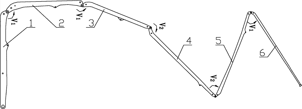
The invention provides a jib device, comprising at least five jibs, each of which is hinged sequentially, and the third jib (3) is a curved jib, when the jib device is in a folded state, the front The three-section boom is folded into an R shape, and the fourth-section boom (4) is folded above the third-section boom (3). When the boom device is in a folded state, the third-section boom (3) ), the fourth boom (4) and the fifth boom (5) are folded into an R shape, and the fifth boom (5) is folded below the third boom (3) . The structure of the jib device in this paper is relatively compact, which improves the utilization rate of the vertical space of the jib and provides space for the arrangement of multi-section jibs. In the same folding space, the number of sections that can be folded is more. Thereby the total length of the boom device is increased, and the cloth flexibility of the boom is improved. In addition, the invention also discloses a construction machine with the above-mentioned boom device.
Description
技术领域 technical field
本发明涉及工程机械技术领域,尤其涉及一种臂架装置。本发明还涉及一种具有上述臂架装置的工程机械。The invention relates to the technical field of engineering machinery, in particular to an arm support device. The present invention also relates to a construction machine with the above-mentioned boom device.
背景技术 Background technique
混凝土泵车是一种典型的工程机械,可将混凝土沿管道输送到建筑工程所需的位置。在工作过程中,混凝土泵车需要通过固定于臂架装置上的输送管将混凝土输送至指定位置,并且随着输送位置的变化,臂架装置需要带动输送管实现展开、收拢以及旋转等动作。混凝土泵车的臂架装置一般包括多节臂架,各节臂架之间能够折叠。Concrete pump truck is a typical construction machinery, which can transport concrete along the pipeline to the required location of the construction project. During the working process, the concrete pump truck needs to transport the concrete to the designated position through the delivery pipe fixed on the boom device, and as the delivery position changes, the boom device needs to drive the delivery pipe to realize unfolding, folding and rotation. The boom device of the concrete pump truck generally includes a multi-section boom, and each section of the boom can be folded.
目前混凝土泵车的臂架所使用的折叠方式主要有R型、Z型以及RZ型等整体折叠方式,其中对于五节以上臂架的臂架装置基本均使用RZ型折叠方式。At present, the folding methods used for the booms of concrete pump trucks mainly include R-type, Z-type and RZ-type overall folding methods, among which the RZ-type folding method is basically used for boom devices with more than five sections.
请参考图1和图2,图1为现有技术中一种典型的臂架装置的折叠示意图;图2为图1所示的臂架装置的俯视图。Please refer to FIG. 1 and FIG. 2 . FIG. 1 is a schematic folded view of a typical boom device in the prior art; FIG. 2 is a top view of the boom device shown in FIG. 1 .
臂架装置的第一节臂架1’与转台铰接,第一节臂架1’、第二节臂架2’以及第三节臂架3’折叠成R型,第三节臂架3’为拐弯臂架,第三节臂架3’、第四节臂架4’以及第五节臂架5’折叠成Z型,第五节臂架5’折叠于第四节臂架4’的上方。然而,第四节臂架4’上方的空间有限,为防止臂架折叠超高,现有技术中六节臂的混凝土泵车中,第六节臂架6’和第五节臂架5’沿同一水平方向顺次布置,并折叠于第四节臂架4’上方,即第五节臂架5’和第六节臂架6’相当于现有技术中五节臂泵车的第五节臂架,与现有技术中五节臂泵车的臂架装置相比,上述六节臂泵车的臂架装置的总长度实质上未发生变化。The first section boom 1' of the boom device is hinged with the turntable, the first section boom 1', the second section boom 2' and the third section boom 3' are folded into an R shape, the third section boom 3' It is a turning boom, the third boom 3', the fourth boom 4' and the fifth boom 5' are folded into a Z shape, the fifth boom 5' is folded on the fourth boom 4' above. However, the space above the fourth section boom 4' is limited. In order to prevent the boom from being folded super high, in the concrete pump truck with six booms in the prior art, the sixth section boom 6' and the fifth section boom 5' Arranged in sequence along the same horizontal direction, and folded above the fourth section boom 4', that is, the fifth section boom 5' and the sixth section boom 6' are equivalent to the fifth section of the five-section boom pump truck in the prior art. Compared with the boom device of the five-arm pump truck in the prior art, the total length of the boom device of the above-mentioned six-arm pump truck does not change substantially.
在上述六节臂泵车的臂架布置中,由于竖直方向上臂架布置高度的约束,还可以通过增加车桥数以提高臂架的长度。在相同的布置高度下,车桥数越大,空间越大,可布置的臂架的长度就越长。但是,增加混凝土泵车的车桥数将影响整车的性能匹配,并且将导致整车的成本急剧增加,不利于节约成本。另外地,上述折叠方式中第六节臂架6’在竖直方向的折叠空间比较小,不便于设置回转机构,从而第六节臂架6’的回转角度比较小,一般回转角度小于110度,导致布料灵活性差。In the boom arrangement of the above-mentioned six-arm pump truck, due to the constraint of the height of the boom arrangement in the vertical direction, the length of the boom can also be increased by increasing the number of axles. Under the same arrangement height, the larger the number of axles, the larger the space, and the longer the length of the boom that can be arranged. However, increasing the number of axles of the concrete pump truck will affect the performance matching of the whole vehicle, and will lead to a sharp increase in the cost of the whole vehicle, which is not conducive to cost saving. In addition, in the above-mentioned folding method, the folding space of the sixth boom 6' in the vertical direction is relatively small, and it is not convenient to install a turning mechanism, so the turning angle of the sixth boom 6' is relatively small, and generally the turning angle is less than 110 degrees. , resulting in poor fabric flexibility.
因此,如何改进臂架装置的折叠方式,使其结构紧凑、竖直空间利用率高,为多节臂架的布置提供空间,从而增加臂架装置的总长度,并提高臂架的布料灵活性,成为本领域技术人员亟待解决的技术难题。Therefore, how to improve the folding method of the boom device so that it has a compact structure and a high utilization rate of vertical space, and provides space for the arrangement of multi-section booms, thereby increasing the total length of the boom device and improving the cloth flexibility of the boom , has become a technical problem to be solved urgently by those skilled in the art.
发明内容 Contents of the invention
本发明的第一个目的是提供一种臂架装置,该臂架装置结构紧凑、竖直空间利用率高,为多节臂架的布置提供了空间,从而增加臂架装置的总长度,并提高臂架的布料灵活性。本发明的第二个目的是提供一种具有上述臂架装置的工程机械。The first object of the present invention is to provide a jib device, which has a compact structure and a high utilization rate of vertical space, provides space for the arrangement of multi-section jibs, thereby increasing the overall length of the jib device, and Improved the cloth flexibility of the jib. The second object of the present invention is to provide a construction machine with the above boom device.
为了实现上述第一个目的,本发明提供了一种臂架装置,包括至少五节臂架,各所述臂架依次铰接,第三节臂架为拐弯臂架,当所述臂架装置处于折叠状态时,前三节臂架折叠为R型,第四节臂架折叠于所述第三节臂架的上方位置,当所述臂架装置处于折叠状态时,第三节臂架、第四节臂架以及第五节臂架折叠为R型,且所述第五节臂架折叠于所述第三节臂架的下方位置。In order to achieve the above-mentioned first purpose, the present invention provides a boom device, comprising at least five booms, each of which is hinged sequentially, and the third boom is a turning boom, when the boom is in the In the folded state, the first three booms are folded into an R shape, and the fourth boom is folded above the third boom. When the boom device is in the folded state, the third boom, the fourth The boom section and the
优选地,所述第五节臂架至少一部分为弧形结构。Preferably, at least a part of the fifth jib is an arc structure.
优选地,所述第五节臂架整体为弧形结构。Preferably, the fifth jib is in an arc shape as a whole.
优选地,所述第五节臂架与所述第四节臂架铰接的端部为弧形结构。Preferably, the hinged ends of the fifth jib and the fourth jib are arc-shaped.
优选地,至少包括六节臂架,当所述臂架装置处于折叠状态时,第四节臂架、第五节臂架以及第六节臂架折叠为Z型。Preferably, at least six jibs are included, and when the jib device is in a folded state, the fourth jib, the fifth jib and the sixth jib are folded into a Z shape.
优选地,至少包括六节臂架,当所述臂架装置处于折叠状态时,所述第四节臂架、第五节臂架以及第六节臂架折叠为R型,且所述第六节臂架折叠于所述第五节臂架和所述第三节臂架之间。Preferably, at least six jibs are included. When the jib device is in the folded state, the fourth jib, the fifth jib and the sixth jib are folded into an R shape, and the sixth jib The section jib is folded between the fifth section jib and the third section jib.
优选地,所述第五节臂架和所述第六节臂架间设有伸缩油缸和连杆机构,以便驱动两臂架相对展开或收拢。Preferably, a telescopic oil cylinder and a link mechanism are provided between the fifth boom and the sixth boom, so as to drive the two booms to expand or retract relative to each other.
为了实现上述第二个目的,本发明还提供了一种工程机械,包括底盘以及设置于所述底盘上的臂架装置,所述臂架装置为上述任一项所述的臂架装置,由于上述的臂架装置具有上述技术效果,具有该臂架装置的工程机械也应具有相应的技术效果。In order to achieve the above second purpose, the present invention also provides a construction machine, including a chassis and a boom device arranged on the chassis, the boom device is the boom device described in any one of the above, because The above-mentioned boom device has the above-mentioned technical effect, and the construction machinery with the boom device should also have the corresponding technical effect.
优选地,所述工程机械具体为混凝土泵车。Preferably, the engineering machinery is specifically a concrete pump truck.
本发明所提供的臂架装置,包括至少五节臂架,各所述臂架依次铰接,第三节臂架为拐弯臂架,当所述臂架装置处于折叠状态时,前三节臂架折叠为R型,第四节臂架折叠于所述第三节臂架的上方位置,当所述臂架装置处于折叠状态时,第三节臂架、第四节臂架以及第五节臂架折叠为R型,且所述第五节臂架折叠于所述第三节臂架的下方位置。The jib device provided by the present invention includes at least five jibs, each of which is hinged sequentially, and the third jib is a turning jib. When the jib device is in a folded state, the first three jibs are folded It is R type, the fourth section boom is folded above the third section boom, when the boom device is in the folded state, the third section boom, the fourth section boom and the fifth section boom It is folded into an R shape, and the fifth jib is folded below the third jib.
本发明所提供的臂架装置折叠时,第五节臂架折叠于第三节臂架的下方,充分利用了第三节臂架下方的空间,与现有技术相比,本文中的臂架装置结构紧凑,提高了臂架竖直方向空间的利用率,为多节臂架的布置提供空间,在相同折叠空间内,可以折叠臂架的数目更多,从而增加了臂架装置的总长度,并避免了通过增加车桥数以提高臂架长度而导致的性能匹配问题和高成本问题;并且,当在同一折叠空间内布置相同节数的臂架时,本臂架装置中各节臂架可以分配比较大的空间,可以在臂架上增加传动或驱动机构,有利于提高臂架的布料灵活性。When the boom device provided by the present invention is folded, the fifth section of the boom is folded under the third section of the boom, making full use of the space under the third section of the boom. Compared with the prior art, the boom in this paper The structure of the device is compact, which improves the utilization rate of the vertical space of the boom and provides space for the arrangement of multi-section booms. In the same folding space, the number of foldable booms is more, thereby increasing the total length of the boom device , and avoid the problem of performance matching and high cost caused by increasing the number of axles to increase the length of the boom; and, when the boom with the same number of sections is arranged in the same folding space, each section of the boom in this boom device The frame can allocate a relatively large space, and a transmission or driving mechanism can be added to the boom frame, which is beneficial to improve the cloth flexibility of the boom frame.
一种优选的方案,所述第五节臂架与所述第四节臂架进行铰接的端部为弧形结构。通过将第五节臂架与第四节臂架的铰接端部设置为弧形结构,使得第五节臂架可折叠在第三节臂架的下方位置,充分了利用了第三节臂架下方的空间。In a preferred solution, the hinged end of the fifth jib and the fourth jib is an arc-shaped structure. By setting the hinged ends of the fifth boom and the fourth boom in an arc-shaped structure, the fifth boom can be folded under the third boom, making full use of the third boom space below.
一种优选的方案,至少包括六节臂架,当所述臂架装置处于折叠状态时,第四节臂架、第五节臂架以及第六节臂架折叠为Z型;或者,包括至少六节臂架,当所述臂架装置处于折叠状态时,所述第四节臂架、第五节臂架以及第六节臂架折叠为R型,且所述第六节臂架折叠于所述第五节臂架和所述第三节臂架之间。与现有技术六节臂架相比,本臂架装置中第六节臂架竖直方向可利用的空间比较大,可以单独折叠为一列,不仅增加了臂架装置总的臂架长度,而且有足够的空间布置驱动第六节臂架工作的机构,可以增加第六节臂架的回转角度,提高臂架的布料灵活性。A preferred solution includes at least six booms, and when the boom device is in a folded state, the fourth boom, the fifth boom and the sixth boom are folded into a Z shape; or, it includes at least The six-section boom, when the boom device is in the folded state, the fourth section boom, the fifth section boom and the sixth section boom are folded into an R shape, and the sixth section boom is folded at Between the fifth boom and the third boom. Compared with the six-section jib in the prior art, the space available in the vertical direction of the sixth section jib in this jib device is relatively large, and can be folded into a row independently, which not only increases the total jib length of the jib device, but also There is enough space to arrange the mechanism that drives the work of the sixth boom, which can increase the rotation angle of the sixth boom and improve the flexibility of the boom.
附图说明 Description of drawings
图1为现有技术中一种典型的臂架装置的折叠示意图;Fig. 1 is a schematic folding diagram of a typical boom device in the prior art;
图2为图1所示臂架装置的俯视图;Fig. 2 is a top view of the boom device shown in Fig. 1;
图3为本发明所提供的臂架装置的一种具体实施方式的结构示意图;Fig. 3 is a schematic structural view of a specific embodiment of the boom device provided by the present invention;
图4为图3所示臂架装置的前三节臂架处于折叠状态的结构示意图;Fig. 4 is a structural schematic diagram of the first three sections of the boom device shown in Fig. 3 in a folded state;
图5为图4所示前三节臂架的俯视图;Fig. 5 is a top view of the first three booms shown in Fig. 4;
图6为图3所示臂架装置的第三节臂架、第四节臂架、第五节臂架以及第六节臂架处于折叠状态的结构示意图;Fig. 6 is a structural schematic diagram of the third section boom, the fourth section boom, the fifth section boom and the sixth section boom of the boom device shown in Fig. 3 in a folded state;
图7为图6所示第三节臂架、第四节臂架、第五节臂架以及第六节臂架处于折叠状态的俯视图;Fig. 7 is a top view of the third section boom, the fourth section boom, the fifth section boom and the sixth section boom shown in Fig. 6 in a folded state;
图8本发明所提供的臂架装置的另一种具体实施方式的结构示意图;Fig. 8 is a structural schematic diagram of another specific embodiment of the boom device provided by the present invention;
图9为图8所示臂架装置的俯视图。Fig. 9 is a top view of the boom device shown in Fig. 8 .
其中,图1和图2中附图标记与部件名称之间的对应关系为:Wherein, the corresponding relationship between reference numerals and component names in Fig. 1 and Fig. 2 is:
第一节臂架1’;第二节臂架2’;第三节臂架3’;第四节臂架4’;第五节臂架5’;第六节臂架6’。The first boom 1'; the second boom 2'; the third boom 3'; the fourth boom 4'; the fifth boom 5'; the sixth boom 6'.
其中,图3至图9中附图标记与部件名称之间的对应关系为:Wherein, the corresponding relationship between reference numerals and component names in Fig. 3 to Fig. 9 is:
第一节臂架1;第二节臂架2;第三节臂架3;第四节臂架4;第五节臂架5;第六节臂架6;逆时针方向V1;顺时针方向V2。The first boom 1; the
具体实施方式 Detailed ways
本发明的目的旨为提供一种臂架装置,该臂架装置结构紧凑、竖直空间利用率高。此外,本发明的另一目的旨为提供一种包括上述臂架装置的工程机械。The object of the present invention is to provide a jib device with a compact structure and high vertical space utilization. In addition, another object of the present invention is to provide a construction machine including the above boom device.
不失一般性,本文以臂架装置在混凝土泵车上的应用为例,介绍本发明的技术方案,本领域内技术人员应当理解,也不排除本发明在其他工程机械上的应用。Without loss of generality, this article takes the application of the boom device on a concrete pump truck as an example to introduce the technical solution of the present invention. Those skilled in the art should understand that the application of the present invention to other construction machinery is not excluded.
为了使本领域的技术人员更好的理解本发明的技术方案,下面结合附图和具体实施方式对本发明作进一步的详细说明。In order to enable those skilled in the art to better understand the technical solutions of the present invention, the present invention will be further described in detail below in conjunction with the accompanying drawings and specific embodiments.
请参看图3至图7,图3为本发明所提供的臂架装置的一种具体实施方式的结构示意图;图4为图3所示臂架装置的前三节臂架处于折叠状态的结构示意图;图5为图4所示前三节臂架的俯视图;图6为图3所示臂架装置的第三节臂架、第四节臂架、第五节臂架以及第六节臂架处于折叠状态的结构示意图;图7为图6所示第三节臂架、第四节臂架、第五节臂架以及第六节臂架处于折叠状态的俯视图。Please refer to Figure 3 to Figure 7, Figure 3 is a schematic structural view of a specific embodiment of the boom device provided by the present invention; Figure 4 is a structural schematic view of the first three sections of the boom device shown in Figure 3 in a folded state ; Fig. 5 is a top view of the first three jibs shown in Fig. 4; Fig. 6 is the third jib of the jib device shown in Fig. 3, the fourth jib, the fifth jib and the sixth jib in Schematic diagram of the structure in the folded state; FIG. 7 is a top view of the third boom, the fourth boom, the fifth boom and the sixth boom shown in FIG. 6 in a folded state.
本发明所提供的臂架装置包括至少五节臂架,各所述臂架依次铰接,臂架装置的相邻臂架之间一般可以设有伸缩油缸,伸缩油缸的一端与前一节臂架铰接,伸缩油缸的另一端可以通过连杆机构与后一节臂架铰接,伸缩油缸用于驱动后一节臂架进行展开或收拢动作。The jib device provided by the present invention comprises at least five jibs, each of which is hinged sequentially. Generally, a telescopic oil cylinder can be provided between adjacent jibs of the jib device, and one end of the telescopic oil cylinder is connected to the previous jib. Hinged, the other end of the telescopic oil cylinder can be hinged with the last section of the boom through the link mechanism, and the telescopic oil cylinder is used to drive the latter section of the boom to expand or retract.
需要说明的是,在本申请中,第一节臂架1的端部与转台铰接,相邻的两节臂架中,将靠近转台的臂架定义为前一节臂架,另一节臂架定义为后一节臂架。It should be noted that, in this application, the end of the first jib 1 is hinged to the turntable, and among the two adjacent jibs, the jib close to the turntable is defined as the front jib and the other jib The frame is defined as the last section of the boom.
臂架装置中第三节臂架3为拐弯臂架,当臂架装置处于折叠状态时,前三节臂架折叠为R型,第四节臂架4折叠于第三节臂架3的上方位置,当所述臂架装置处于折叠状态时,第三节臂架3、第四节臂架4以及第五节臂架5折叠为R型,且第五节臂架5折叠于第三节臂架3的正下方位置。The
本发明所提供的臂架装置折叠时,第五节臂架5折叠于第三节臂架3的正下方,充分利用了第三节臂架3下方的空间,与现有技术相比,本文中的臂架装置结构紧凑,提高了臂架竖直方向空间的利用率,为多节臂架的布置提供空间,在相同折叠空间内,可以折叠臂架的数目更多,从而增加了臂架装置的总长度,并避免了通过增加车桥数以提高臂架长度而导致的性能匹配问题和高成本问题;并且,当在同一折叠空间内布置相同节数的臂架时,本臂架装置中各节臂架可以分配比较大的空间,可以在臂架上增加传动或驱动机构,有利于提高臂架的布料灵活性。When the jib device provided by the present invention is folded, the
为了便于臂架折叠方式的实现,可以将第五节臂架5的结构设计为具有至少一部分为弧形结构,使得第五节臂架可折叠在第三节臂架的下方位置,充分了利用了第三节臂架下方的空间。在具体实施方式中,第五节臂架5整体为弧形结构,或者第五节臂架5与所述第四节臂架4的铰接端部为弧形结构。In order to facilitate the realization of the folding mode of the boom, the structure of the
在上述臂架装置的基础上,对于至少具有六节臂架的臂架装置,当臂架装置处于折叠状态时,第五节臂架和第六节臂架可以处于叠置,即上下层两列折叠放置,下面给出臂架装置的两种具体的折叠方式。On the basis of the above-mentioned boom device, for a boom device with at least six booms, when the boom device is in a folded state, the fifth boom and the sixth boom can be stacked, that is, the upper and lower two The column is folded and placed. Two specific folding methods of the boom device are given below.
请参考图6和图7,在一种具体实施方式中,臂架装置至少包括六节臂架,第五节臂架5整体为弧形结构,当所述臂架装置处于折叠状态时,第四节臂架4、第五节臂架5以及第六节臂架6折叠为Z型。Please refer to Fig. 6 and Fig. 7, in a specific embodiment, the boom device includes at least six booms, and the
臂架装置工作前,各节臂架的展开方向请参考图3,第二节臂架2与第一节臂架1、第三节臂架3与第二节臂架2、以及第六节臂架6与第五节臂架5之间的相对展开方向相同,均沿逆时针方向V1展开;第四节臂架4与第三节臂架3、第五节臂架5与第四节臂架4之间的相对展开方向相同,均沿顺时针方向V2展开。Before the boom device works, please refer to Figure 3 for the deployment direction of each section of the boom, the second section of the
与现有技术六节臂架相比,本臂架装置中第六节臂架6竖直方向可利用的空间比较大,可以单独折叠为一列,不仅增加了臂架装置总的臂架长度,而且有足够的空间布置驱动第六节臂架6工作的机构,可以增加第六节臂架6的回转角度,提高布料灵活性。Compared with the six-section jib of the prior art, the space available in the vertical direction of the
而且,Z型布置方式有利于臂架装置在比较小的空间中的展开。Moreover, the Z-shaped arrangement facilitates the deployment of the boom device in a relatively small space.
请参考图8和图9,图8本发明所提供的臂架装置的另一种具体实施方式的结构示意图,因前三节臂架的折叠状态与现有技术相同,本图中只给出后几节臂架的折叠状态示意图;图9为图8所示臂架装置的俯视图。Please refer to Fig. 8 and Fig. 9. Fig. 8 is a structural schematic diagram of another specific embodiment of the boom device provided by the present invention. Because the folded state of the first three sections of the boom is the same as that of the prior art, only the rear is shown in this figure. Schematic diagram of the folded state of several sections of the jib; Figure 9 is a top view of the jib device shown in Figure 8 .
在该实施例中,臂架装置至少包括六节臂架,第五节臂架5与所述第四节臂架4的铰接端部为弧形结构,当所述臂架装置处于折叠状态时,第四节臂架4、第五节臂架5以及第六节臂架6折叠为R型,且第六节臂架6折叠于第五节臂架5和第三节臂架3之间。In this embodiment, the boom device includes at least six booms, and the hinged end of the
如图8所示,本实施例中第五节臂架5相对第四节臂架4的展开方向、第六节臂架6相对第五节臂架5的展开方向均为顺时针方向V2。As shown in FIG. 8 , in this embodiment, the deployment direction of the
该臂架折叠方式中第四节臂架4、第五节臂架5以及第六节臂架6折叠为R型,可以进一步充分利用前两节臂架之间的空间,增加臂架装置整体结构的紧凑性。In this boom folding method, the fourth boom 4, the
一般地,相邻两臂架的展开或收拢是通过设置于两者间的伸缩油缸实现的。Generally, the expansion or contraction of two adjacent boom frames is realized by a telescopic oil cylinder arranged between them.
上述各实施方案中,上述各实施例中第五节臂架5和第六节臂架6间可以设有伸缩油缸和连杆机构,以便驱动两臂架相对展开或收拢;与现有技术中第五节臂架和第六节臂架只设有伸缩油缸相比,连杆机构可以实现比较大的变幅运动,第五节臂架5和第六节臂架6通过伸缩油缸和连杆机构相配合方式实现相互运动,可以增大第六节臂架6的回转角度,增加布料灵活性。In each of the above-mentioned embodiments, a telescopic oil cylinder and a connecting rod mechanism may be provided between the
当然,本文中所述臂架装置中臂架的数量不仅局限于六节臂架,还可以为更多节臂架,例如七节臂架,在七节臂架的臂架装置中,前六节臂架的折叠方式可以为上述任一实施例中描述的折叠方式,第六节臂架与第七节臂架的布置方式可以根据混凝土泵车的使用需要布置,例如当臂架处于折叠状态时,第六节臂架和第七节臂架折叠于同一水平面上,与六节臂架装置的混凝土泵车相比,七节臂架具有比较高的工作灵活性。Of course, the number of jibs in the jib device described herein is not limited to the six-section jib, but can also be more jibs, such as seven-section jibs. In the jib device of the seven-section jib, the first six The folding method of the section boom can be the folding method described in any of the above embodiments, and the arrangement of the sixth section boom and the seventh section boom can be arranged according to the use needs of the concrete pump truck, for example, when the boom is in the folded state At the same time, the sixth boom and the seventh boom are folded on the same level. Compared with the concrete pump truck with six booms, the seven booms have higher working flexibility.
在本发明各实施例中,所谓R型折叠即为该组折叠臂架中后一节臂架相对前一节臂架的折叠方向均相同;所谓Z型折叠即为该组折叠臂架中后一节臂架相对前一节臂架的折叠方向依次相反。In each embodiment of the present invention, the so-called R-type folding means that the folding direction of the rear boom in the group of folding booms is the same as that of the previous boom; The folding direction of one section of the jib is opposite to that of the previous section of the jib.
需要说明的是,本文中所述的顺时针方向、逆时针方向只是以图3、图8中各臂架位置为参考,为了表述技术方案的简洁方便,本领域内技术人员应当理解,本文所用的方位词不应限制本发明的申请范围。It should be noted that the clockwise direction and counterclockwise direction described in this article are only based on the positions of the booms in Fig. 3 and Fig. 8. The location words should not limit the application scope of the present invention.
本发明还提供了一种工程机械,包括底盘以及设置于所述底盘上的臂架装置,所述臂架装置为上述任一实施方式中所述的臂架装置。由于上述的臂架装置具有上述技术效果,具有该臂架装置的工程机械也应具有相应的技术效果。The present invention also provides a construction machine, including a chassis and a boom device arranged on the chassis, and the boom device is the boom device described in any one of the above-mentioned embodiments. Since the above-mentioned boom device has the above-mentioned technical effects, the engineering machinery having the boom device should also have corresponding technical effects.
在一种优选的实施方式中,上述工程机械可以为混凝土泵车。In a preferred embodiment, the construction machinery mentioned above may be a concrete pump truck.
此外,该混凝土泵车的其他部分的技术特征可以参见现有技术,在此不再赘述。In addition, the technical features of other parts of the concrete pump truck can refer to the prior art, and will not be repeated here.
以上对本发明所提供的一种臂架装置及工程机械进行了详细介绍。以上所述仅是发明的优选实施方式的描述,应当指出,由于文字表达的有限性,而在客观上存在无限的具体结构,对于本技术领域的普通技术人员来说,在不脱离本发明原理的前提下,还可以做出若干改进和润饰,这些改进和润饰也应视为本发明的保护范围。The boom device and construction machinery provided by the present invention have been introduced in detail above. The above is only a description of the preferred embodiment of the invention. It should be pointed out that due to the limitation of literal expression, there are objectively unlimited specific structures. Under the premise of the invention, some improvements and modifications can also be made, and these improvements and modifications should also be regarded as the protection scope of the present invention.
Claims (10)
Priority Applications (2)
| Application Number | Priority Date | Filing Date | Title |
|---|---|---|---|
| CN 201110283835 CN102390307B (en) | 2011-09-22 | 2011-09-22 | Arm support device and engineering machinery |
| PCT/CN2012/074044 WO2013040893A1 (en) | 2011-09-22 | 2012-04-14 | Boom device and engineering machinery |
Applications Claiming Priority (1)
| Application Number | Priority Date | Filing Date | Title |
|---|---|---|---|
| CN 201110283835 CN102390307B (en) | 2011-09-22 | 2011-09-22 | Arm support device and engineering machinery |
Publications (2)
| Publication Number | Publication Date |
|---|---|
| CN102390307A CN102390307A (en) | 2012-03-28 |
| CN102390307B true CN102390307B (en) | 2013-07-17 |
Family
ID=45857737
Family Applications (1)
| Application Number | Title | Priority Date | Filing Date |
|---|---|---|---|
| CN 201110283835 Active CN102390307B (en) | 2011-09-22 | 2011-09-22 | Arm support device and engineering machinery |
Country Status (2)
| Country | Link |
|---|---|
| CN (1) | CN102390307B (en) |
| WO (1) | WO2013040893A1 (en) |
Families Citing this family (4)
| Publication number | Priority date | Publication date | Assignee | Title |
|---|---|---|---|---|
| CN102390307B (en) * | 2011-09-22 | 2013-07-17 | 三一汽车制造有限公司 | Arm support device and engineering machinery |
| CN102650166A (en) * | 2012-04-19 | 2012-08-29 | 三一重工股份有限公司 | Arm support device and construction machinery |
| CN104695710B (en) * | 2013-12-09 | 2017-04-05 | 北汽福田汽车股份有限公司 | A kind of boom device and engineering machinery |
| CN114772484A (en) * | 2022-04-22 | 2022-07-22 | 三一汽车制造有限公司 | Boom device and working machine |
Citations (4)
| Publication number | Priority date | Publication date | Assignee | Title |
|---|---|---|---|---|
| US3825137A (en) * | 1971-12-08 | 1974-07-23 | Sheppard Equipment Ltd | Vehicle for transporting a container |
| CN2703896Y (en) * | 2004-06-29 | 2005-06-08 | 上海鸿得利机械制造有限公司 | Cantilever-crane type concrete transfer pump |
| CN101793092A (en) * | 2010-02-05 | 2010-08-04 | 三一重工股份有限公司 | Concrete pump truck and boom device thereof |
| CN201857760U (en) * | 2010-10-25 | 2011-06-08 | 山推楚天工程机械有限公司 | Sixth-section arm foldable for 180 degrees of concrete pump truck |
Family Cites Families (6)
| Publication number | Priority date | Publication date | Assignee | Title |
|---|---|---|---|---|
| DE3445130A1 (en) * | 1984-12-11 | 1986-02-20 | Maschinenfabrik Walter Scheele GmbH & Co KG, 4750 Unna-Massen | Multi-armed concrete-distributing device |
| DE10328769A1 (en) * | 2003-06-25 | 2005-01-20 | Putzmeister Ag | Articulated mast for mobile concrete pumps |
| CN201753529U (en) * | 2010-05-27 | 2011-03-02 | 山东柳工机械设备有限公司 | Crawler walking-type concrete pump truck |
| CN201738589U (en) * | 2010-08-19 | 2011-02-09 | 三一重工股份有限公司 | Arm support system and concrete pump truck |
| CN201924601U (en) * | 2010-09-29 | 2011-08-10 | 北汽福田汽车股份有限公司 | Folding cantilever crane structure and concrete pump truck with same |
| CN102390307B (en) * | 2011-09-22 | 2013-07-17 | 三一汽车制造有限公司 | Arm support device and engineering machinery |
-
2011
- 2011-09-22 CN CN 201110283835 patent/CN102390307B/en active Active
-
2012
- 2012-04-14 WO PCT/CN2012/074044 patent/WO2013040893A1/en not_active Ceased
Patent Citations (4)
| Publication number | Priority date | Publication date | Assignee | Title |
|---|---|---|---|---|
| US3825137A (en) * | 1971-12-08 | 1974-07-23 | Sheppard Equipment Ltd | Vehicle for transporting a container |
| CN2703896Y (en) * | 2004-06-29 | 2005-06-08 | 上海鸿得利机械制造有限公司 | Cantilever-crane type concrete transfer pump |
| CN101793092A (en) * | 2010-02-05 | 2010-08-04 | 三一重工股份有限公司 | Concrete pump truck and boom device thereof |
| CN201857760U (en) * | 2010-10-25 | 2011-06-08 | 山推楚天工程机械有限公司 | Sixth-section arm foldable for 180 degrees of concrete pump truck |
Also Published As
| Publication number | Publication date |
|---|---|
| WO2013040893A1 (en) | 2013-03-28 |
| CN102390307A (en) | 2012-03-28 |
Similar Documents
| Publication | Publication Date | Title |
|---|---|---|
| WO2013123793A1 (en) | Boom device and concrete pump truck | |
| CN102409857B (en) | Boom device and concrete pump truck | |
| CN102359277B (en) | Arm frame device and engineering machine | |
| CN202376656U (en) | Folding arm rack and elevating platform fire truck with same | |
| WO2009036627A1 (en) | Support device for walking machines | |
| WO2013026279A1 (en) | Concrete pump truck and arm stand device thereof | |
| WO2012171402A1 (en) | Boom structure and concrete pumping vehicle | |
| CN102518305B (en) | Concrete pump truck boom and concrete pump truck | |
| CN202441063U (en) | Rotary table and engineering machinery and arm support devices thereof | |
| CN102991477B (en) | Construction machinery and its outriggers | |
| WO2013040893A1 (en) | Boom device and engineering machinery | |
| CN100497052C (en) | Telescopic support leg for travel machine and concrete pump truck with the same | |
| CN102659038B (en) | Cranes and their super-lifting devices | |
| CN204212430U (en) | A kind of boom system and concrete mixer | |
| CN104444864A (en) | Movable crane and supporting leg structure thereof | |
| CN210885040U (en) | Swing supporting leg and engineering mechanical equipment | |
| CN106276641B (en) | Body frame structure for automotive and crane | |
| CN211037853U (en) | Six-section concrete pump truck arm support device | |
| CN202346654U (en) | Telescopic lattice arms and construction machinery | |
| CN203022349U (en) | Boom device and engineering machinery | |
| CN115142681B (en) | Construction machinery | |
| CN102491202B (en) | traveling crane | |
| CN203529880U (en) | Hydraulic aerial cage | |
| CN203715125U (en) | Crane as well as guying device thereof | |
| CN202401770U (en) | Concrete pump truck boom and concrete pump truck |
Legal Events
| Date | Code | Title | Description |
|---|---|---|---|
| C06 | Publication | ||
| PB01 | Publication | ||
| C10 | Entry into substantive examination | ||
| SE01 | Entry into force of request for substantive examination | ||
| ASS | Succession or assignment of patent right |
Owner name: SANY AUTOMOBILE MANUFACTURING CO., LTD. Free format text: FORMER OWNER: SANYI HEAVY INDUSTRY CO LTD Effective date: 20130502 |
|
| C41 | Transfer of patent application or patent right or utility model | ||
| TA01 | Transfer of patent application right |
Effective date of registration: 20130502 Address after: 410100 Changsha economic and Technological Development Zone, Hunan City, the 31 industrial city Applicant after: Sany Automobile Manufacturing Co.,Ltd. Address before: 410100 Changsha economic and Technological Development Zone, Hunan City, the 31 industrial city Applicant before: SANY HEAVY INDUSTRY Co.,Ltd. |
|
| C14 | Grant of patent or utility model | ||
| GR01 | Patent grant | ||
| TR01 | Transfer of patent right | ||
| TR01 | Transfer of patent right |
Effective date of registration: 20220225 Address after: 410000 3rd floor, Sany administrative center, Sany industrial city, Sany Road, Changsha Economic and Technological Development Zone, Hunan Province Patentee after: SANY GROUP Co.,Ltd. Address before: 410100 31 industrial city, Changsha economic and Technological Development Zone, Hunan Patentee before: Sany Automobile Manufacturing Co.,Ltd. |
|
| PE01 | Entry into force of the registration of the contract for pledge of patent right | ||
| PE01 | Entry into force of the registration of the contract for pledge of patent right |
Denomination of invention: A boom device and construction machinery Effective date of registration: 20231107 Granted publication date: 20130717 Pledgee: Business Department of Hunan Branch of China Construction Bank Co.,Ltd. Pledgor: SANY GROUP Co.,Ltd. Registration number: Y2023980064163 |