CN102354882B - Electrical connector - Google Patents
Electrical connector Download PDFInfo
- Publication number
- CN102354882B CN102354882B CN2011102578474A CN201110257847A CN102354882B CN 102354882 B CN102354882 B CN 102354882B CN 2011102578474 A CN2011102578474 A CN 2011102578474A CN 201110257847 A CN201110257847 A CN 201110257847A CN 102354882 B CN102354882 B CN 102354882B
- Authority
- CN
- China
- Prior art keywords
- electrical connector
- conductive terminals
- tongue plate
- conductive
- mounting
- Prior art date
- Legal status (The legal status is an assumption and is not a legal conclusion. Google has not performed a legal analysis and makes no representation as to the accuracy of the status listed.)
- Active
Links
Images

Classifications
-
- H—ELECTRICITY
- H01—ELECTRIC ELEMENTS
- H01R—ELECTRICALLY-CONDUCTIVE CONNECTIONS; STRUCTURAL ASSOCIATIONS OF A PLURALITY OF MUTUALLY-INSULATED ELECTRICAL CONNECTING ELEMENTS; COUPLING DEVICES; CURRENT COLLECTORS
- H01R13/00—Details of coupling devices of the kinds covered by groups H01R12/70 or H01R24/00 - H01R33/00
- H01R13/646—Details of coupling devices of the kinds covered by groups H01R12/70 or H01R24/00 - H01R33/00 specially adapted for high-frequency, e.g. structures providing an impedance match or phase match
- H01R13/6461—Means for preventing cross-talk
- H01R13/6471—Means for preventing cross-talk by special arrangement of ground and signal conductors, e.g. GSGS [Ground-Signal-Ground-Signal]
-
- H—ELECTRICITY
- H01—ELECTRIC ELEMENTS
- H01R—ELECTRICALLY-CONDUCTIVE CONNECTIONS; STRUCTURAL ASSOCIATIONS OF A PLURALITY OF MUTUALLY-INSULATED ELECTRICAL CONNECTING ELEMENTS; COUPLING DEVICES; CURRENT COLLECTORS
- H01R13/00—Details of coupling devices of the kinds covered by groups H01R12/70 or H01R24/00 - H01R33/00
- H01R13/648—Protective earth or shield arrangements on coupling devices, e.g. anti-static shielding
- H01R13/658—High frequency shielding arrangements, e.g. against EMI [Electro-Magnetic Interference] or EMP [Electro-Magnetic Pulse]
- H01R13/6581—Shield structure
- H01R13/6585—Shielding material individually surrounding or interposed between mutually spaced contacts
- H01R13/6589—Shielding material individually surrounding or interposed between mutually spaced contacts with wires separated by conductive housing parts
-
- H—ELECTRICITY
- H01—ELECTRIC ELEMENTS
- H01R—ELECTRICALLY-CONDUCTIVE CONNECTIONS; STRUCTURAL ASSOCIATIONS OF A PLURALITY OF MUTUALLY-INSULATED ELECTRICAL CONNECTING ELEMENTS; COUPLING DEVICES; CURRENT COLLECTORS
- H01R24/00—Two-part coupling devices, or either of their cooperating parts, characterised by their overall structure
- H01R24/60—Contacts spaced along planar side wall transverse to longitudinal axis of engagement
- H01R24/62—Sliding engagements with one side only, e.g. modular jack coupling devices
- H01R24/64—Sliding engagements with one side only, e.g. modular jack coupling devices for high frequency, e.g. RJ 45
Landscapes
- Details Of Connecting Devices For Male And Female Coupling (AREA)
Abstract
一种电连接器,包括绝缘本体、若干第一、第二导电端子以及遮蔽壳体,所述绝缘本体包括一舌板,所述遮蔽壳体位于舌板外围以形成收容空间,所述舌板设有自由末端及若干靠近自由末端的凹陷,每一根第一导电端子包括弹性第一接触部、第一安装部以及第一焊接部;所述每一根第二导电端子包括平板状第二接触部、第二安装部以及第二焊接部;所述第一、第二安装部排列成相互平行的两排,所述第一接触部与第二接触部共同固定在所述舌板的同一侧,所述电连接器还包括位于第一、第二安装部之间的金属片。
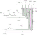
An electrical connector includes an insulating body, a plurality of first and second conductive terminals, and a shielding shell, the insulating body includes a tongue plate, and the shielding shell is located on the periphery of the tongue plate to form a receiving space, the tongue plate A free end and a number of depressions near the free end are provided. Each first conductive terminal includes a first elastic contact portion, a first mounting portion, and a first welding portion; each second conductive terminal includes a flat second The contact part, the second installation part and the second welding part; the first and second installation parts are arranged in two rows parallel to each other, and the first contact part and the second contact part are jointly fixed on the same side of the tongue plate On the side, the electrical connector further includes a metal sheet located between the first and second mounting parts.
Description
本发明为申请人在2008年8月5日申请的发明专利第200810146166.9号发明名称为电连接器的分案申请。 The present invention is a divisional application of the invention patent No. 200810146166.9 filed by the applicant on August 5, 2008, and the name of the invention is an electrical connector.
【技术领域】【Technical field】
本发明涉及一种可提高信号传输质量的电连接器。 The invention relates to an electrical connector capable of improving signal transmission quality.
【背景技术】【Background technique】
随着电子工业的迅速发展,对电子产品信号传输速率的要求正变得越来越高。为了达到上述要求,电子产品内部的电连接器往往会增加额外的导电端子,通过增加的导电端子来提高信号传输的速率。但是,随着导电端子数量的增多带来的直接问题是各种导电端子在信号传输过程中容易产生相互串扰,极大的降低了信号传输的质量,不能达到预期的效果。 With the rapid development of the electronic industry, the requirements for the signal transmission rate of electronic products are becoming higher and higher. In order to meet the above requirements, electrical connectors inside electronic products often add additional conductive terminals, and the rate of signal transmission is increased through the added conductive terminals. However, the direct problem brought about by the increase in the number of conductive terminals is that the various conductive terminals are prone to mutual crosstalk during signal transmission, which greatly reduces the quality of signal transmission and cannot achieve the desired effect.
所以有必要设计出一种能够解决上述问题的电连接器。 Therefore, it is necessary to design an electrical connector that can solve the above problems.
【发明内容】【Content of invention】
本发明所要解决的技术问题在于提供一种降低信号串扰的电连接器。 The technical problem to be solved by the present invention is to provide an electrical connector that reduces signal crosstalk.
为解决上述技术问题,本发明采用如下技术方案: 一种电连接器,包括绝缘本体、固持于绝缘本体上的若干第一、第二导电端子以及包覆绝缘本体的遮蔽壳体,所述绝缘本体包括一舌板,所述遮蔽壳体位于所述舌板外围以形成收容空间,所述舌板设有自由末端及若干靠近自由末端的凹陷,每一根第一导电端子包括突出舌板之外而延伸入收容空间内的弹性第一接触部、第一安装部以及自第一安装部延伸的第一焊接部;所述每一根第二导电端子包括贴置在舌板的凹陷中而暴露在收容空间内的平板状第二接触部、第二安装部以及自第二安装部延伸的第二焊接部;所述第一、第二安装部排列成相互平行的两排,所述第一接触部与第二接触部共同位于所述舌板沿厚度方向的同一侧,其中,所述电连接器还包括位于第一、第二安装部之间的金属片。 In order to solve the above-mentioned technical problems, the present invention adopts the following technical solutions: An electrical connector, including an insulating body, a plurality of first and second conductive terminals held on the insulating body, and a shielding shell covering the insulating body, the insulating body The body includes a tongue plate, the shielding shell is located on the periphery of the tongue plate to form a receiving space, the tongue plate is provided with a free end and a number of depressions near the free end, and each first conductive terminal includes a protruding tongue plate The elastic first contact part extending into the receiving space, the first installation part and the first welding part extending from the first installation part; each of the second conductive terminals is attached to the depression of the tongue plate and The flat second contact portion, the second mounting portion and the second welding portion extending from the second mounting portion exposed in the accommodation space; the first and second mounting portions are arranged in two rows parallel to each other, and the first The first contact portion and the second contact portion are located on the same side of the tongue plate along the thickness direction, wherein the electrical connector further includes a metal sheet located between the first and second mounting portions.
相较于现有技术,本发明通过在第一、第二安装部之间设置金属片,避免第一、第二导电端在子信号传输过程中相互之间产生串扰,提高了电连接器的信号传输质量。 Compared with the prior art, the present invention avoids crosstalk between the first and second conductive terminals during the sub-signal transmission process by arranging a metal sheet between the first and second mounting parts, and improves the reliability of the electrical connector. Signal transmission quality.
【附图说明】【Description of drawings】
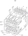
图1是本发明电连接器的立体组合图。 FIG. 1 is a three-dimensional assembled view of the electrical connector of the present invention.
图2是图1的另一角度的立体组合图。 Fig. 2 is a three-dimensional combined view of Fig. 1 from another angle.
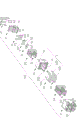
图3是本发明电连接器的立体分解图。 Fig. 3 is a three-dimensional exploded view of the electrical connector of the present invention.
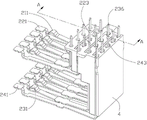
图4是本发明电连接器的部分立体组合图,其中第二、第四导电端子处于未被弯折前的状态。 FIG. 4 is a partial perspective assembled view of the electrical connector of the present invention, wherein the second and fourth conductive terminals are in the state before being bent.
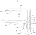
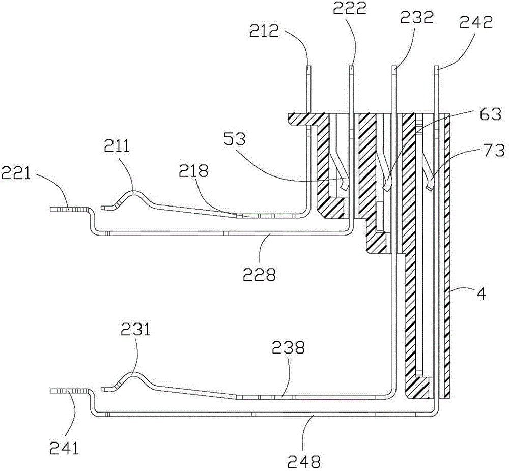
图5是本发明电连接器的导电端子及接地片的侧视图。 Fig. 5 is a side view of the conductive terminal and the grounding piece of the electrical connector of the present invention.
图6是图5中导电端子及接地片安装于安装座上的立体组合图。 FIG. 6 is a three-dimensional assembled view of the conductive terminal and the ground plate installed on the mounting base in FIG. 5 .
图7是沿图6中A-A线方向的剖面图。 Fig. 7 is a sectional view along the line A-A in Fig. 6 .
图8是本发明电连接器安装座的立体示意图。 FIG. 8 is a schematic perspective view of the mounting base of the electrical connector of the present invention.
【具体实施方式】【Detailed ways】
请参照图1至图4所示,本发明电连接器100用以焊接于电路板(未图示)上,其包括绝缘本体1、固持于绝缘本体1上的若干导电端子2及包覆于绝缘本体1外围的金属遮蔽壳体3。所述绝缘本体1在本实施方式中由分开设置的绝缘块10及插接于绝缘块10上的上、下舌板50、60组成(容后详述)。所述遮蔽壳体3位于上、下舌板50、60的外围以形成上、下设置的第一、第二收容空间70、80(如图1所示)。
1 to 4, the
本发明电连接器100在本实施方式中为包括上、下接口的堆叠式结构,当然,在其它实施方式中,本发明电连接器100也可以为设置为左右并排的结构或只设有一个接口等等。
In this embodiment, the
请参照图3及图4所示,所述绝缘块10包括大致呈长方体的基部11及自基部11前表面110向前突伸的分隔板14。所述分隔板14将绝缘块10分隔为上部区域12及下部区域13,其中,上、下部区域12、13分别对应设有用于收容上、下舌板50、60的U形凹槽121、131及若干用以收容导电端子2的收容槽122、132。所述收容槽122、132进一步向后延伸并贯穿基部11的后表面111。
Referring to FIGS. 3 and 4 , the
每一个上、下舌板50、60均对应包括一个矩形主体部501、601及一对自主体部501、601两侧向后延伸的扣持臂502、602。所述主体部501、601对应包括自由末端503、603及若干靠近自由末端503、603的凹陷504、604(如图2所示)。
Each upper and
请参照图5至图7所示,所述导电端子2包括位于上、下接口内的上排导电端子及下排导电端子。所述下排导电端子包括4根第一导电端子21及5根第二导电端子22,其中,每一根第一导电端子21包括弹性第一接触部211、垂直于第一接触部211的第一安装部218自第一安装部218向下延伸的第一焊接部212。所述4根第一导电端子21是符合USB协会规定的A型插座连接器的端子标准,其用以传输USB 2.0信号。具体地讲,这4根第一导电端子21分别为电源端子213(VBUS)、负信号端子214(D-)、正信号端子215(D+)及接地端子216(GND)。所述每一根第二导电端子22包括平板状的第二接触部221、垂直于第二接触部221的第二安装部228及自第二安装部228向下延伸的第二焊接部222。所述5根第二导电端子22包括一根位于中间的接地端子223及位于接地端子223两侧且用于传输高速差分信号的两对差分信号端子224、225及226、227。
Please refer to FIG. 5 to FIG. 7 , the
所述上排导电端子与下排导电端子结构类似,上排导电端子包括4根第三导电端子23及5根第四导电端子24,其中,每一根第三导电端子23包括弹性第三接触部231、垂直于第三接触部231的第三安装部238自第三安装部238向下延伸的第三焊接部232。所述4根第三导电端子23也是符合USB协会规定的A型插座连接器的端子标准,其用以传输USB 2.0信号。具体地讲,这4根第三导电端子23分别为电源端子233(VBUS)、负信号端子234(D-)、正信号端子235(D+)及接地端子236(GND)。所述每一根第四导电端子24包括平板状的第四接触部241、垂直于第四接触部241的第四安装部248及自第四安装部248向下延伸的第四焊接部242。所述5根第四导电端子24包括一根位于中间的接地端子243及位于接地端子243两侧且用于传输高速差分信号的两对差分信号端子244、245及246、247。
The structure of the upper row of conductive terminals is similar to that of the lower row of conductive terminals. The upper row of conductive terminals includes four third
在本实施方式中,所述第二、第四导电端子22、24分别对应镶埋成型于下、上舌板60、50上(如图4所示)。所述第二、第四接触部221、241被对应贴置在下、上舌板60、50的凹陷604、504上。当然,在其他实施方式中,所述上、下舌板50、60也可以与绝缘块10一体成型,此时,所述上、下舌板50、60可通过开设收容槽的形式来收容对应的第二、第四导电端子22、24。
In this embodiment, the second and fourth
请参照图1至图3所示,所述遮蔽壳体3为由金属片冲压、弯折而成的中空结构,其包括顶面31、两侧面32及底面33。所述两侧面32及底面33均分别设有纵长延伸入第一、第二收容空间70、80内用以抵压对接插头(未图示)的弹臂34。所述两侧面32还设有向下延伸并穿过电路板的锁板件35。
Please refer to FIG. 1 to FIG. 3 , the
所述电连接器100还设有扣持在分隔板14上的前壳体36及扣持在遮蔽壳体3后部的后壳体37。所述前壳体36包括一对固定于遮蔽壳体3前部的固定臂361。
The
组装时,所述第二导电端子22及第四导电端子24镶埋成型于下、上舌板60、50内以形成两个模组(如图4所示)。然后,将这两个模组分别插入到绝缘块10的U形凹槽121、131内,所述扣持臂502、602卡在凹槽121、131里,进而将模组固定在绝缘块10上。所述主体部501、601向前突出于基部11的前表面110。所述第二、第四焊接部222、242穿出对应的收容槽122、132外。然后,所述第二、第四焊接部222、242被向下弯折成与对应的第二、第四接触部221、241大致成直角。所述第一、第三导电端子21、23自绝缘块10的后表面111而插入到对应的收容槽122、132内,所述第一、第三接触部211、231突出下、上舌板60、50之外。所述第二、第四接触部221、241被对应贴置在下、上舌板60、50的凹陷604、504上。所以,第一接触部211与第二接触部221位于不同的水平面(如图5所示),其中,第二接触部221相较于第一接触部211更靠近下舌板60的自由末端603。同理,第三接触部231与第四接触部241位于不同的水平面(如图5所示),其中,第四接触部241相较于第三接触部231更靠近上舌板50的自由末端503。
During assembly, the second
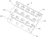
为了将导电端子2的所有焊接部212、222、232、242固定在预定的位置以便于焊接,所述电连接器100还设有一个安装于绝缘块10底面的安装座4。请参照图6至图8所示,所述安装座4包括若干穿孔及若干狭槽。其中,所述穿孔包括排列成相互平行的第一穿孔41、第二穿孔42、第三穿孔43、第四穿孔44。所述狭槽包括排列成相互平行的第一狭槽45、第二狭槽46、第三狭槽47。所述第一狭槽45位于第一、第二穿孔41、42之间;所述第二狭槽46位于第二、第三穿孔42、43之间;所述第三狭槽47位于第三、第四穿孔43、44之间。所述导电端子2的所有焊接部212、222、232、242均对应穿过第一、第二、第三、第四穿孔41、42、43、44且延伸出安装座4外,便于焊接于电路板上。
In order to fix all the
为了降低导电端子2在信号传输过程中的串扰(Cross-talk),所述电连接器100还包括收容于第一、第二、第三狭槽45、46、47内的第一、第二、第三金属接地片5、6、7。每一个接地片5、6、7分别包括自下而上固定于第一、第二、第三狭槽45、46、47内的竖直固定部51、61、71及若干间隔部52、62、72。所述接地片5、6、7还对应包括与第二、第三、第四安装部228、238、248电性及机械连接的弹性臂53、63、73。如此设置,相当于扩大了接地端子243、236、223的表面积,这样接地端子243、236、223便具有更好的屏蔽效果。同时,所述接地端子243、236、223同样可以通过接地片5、6、7来调节阻抗匹配,达到最理想的信号传输效果。值得一提的是,本发明电连接器100的接地片5、6、7是安装于安装座4上,所以没有影响到整个电连接器100尺寸。另外,所述接地片5、6、7也无需焊接到电路板上,所以在装配过程中也很方便。
In order to reduce the crosstalk (Cross-talk) of the
综上所述,以上仅为本发明的较佳实施例而已,不应以此限制本发明的范围,即凡是依本发明权利要求书及发明说明书内容所作的简单的等效变化与修饰,皆应仍属本发明专利涵盖的范围内。 In summary, the above are only preferred embodiments of the present invention, and should not limit the scope of the present invention, that is, all simple equivalent changes and modifications made according to the claims of the present invention and the contents of the description of the invention are all Should still belong to the scope covered by the patent of the present invention.
Claims (10)
Applications Claiming Priority (3)
| Application Number | Priority Date | Filing Date | Title |
|---|---|---|---|
| US11/999,434 US7604490B2 (en) | 2007-12-05 | 2007-12-05 | Electrical connector with improved ground piece |
| US11/999434 | 2007-12-05 | ||
| US11/999,434 | 2007-12-05 |
Related Parent Applications (1)
| Application Number | Title | Priority Date | Filing Date |
|---|---|---|---|
| CN2008101461669A Division CN101453088B (en) | 2007-12-05 | 2008-08-06 | electrical connector |
Publications (2)
| Publication Number | Publication Date |
|---|---|
| CN102354882A CN102354882A (en) | 2012-02-15 |
| CN102354882B true CN102354882B (en) | 2013-10-02 |
Family
ID=40722122
Family Applications (2)
| Application Number | Title | Priority Date | Filing Date |
|---|---|---|---|
| CN2011102578474A Active CN102354882B (en) | 2007-12-05 | 2008-08-06 | Electrical connector |
| CN2008101461669A Active CN101453088B (en) | 2007-12-05 | 2008-08-06 | electrical connector |
Family Applications After (1)
| Application Number | Title | Priority Date | Filing Date |
|---|---|---|---|
| CN2008101461669A Active CN101453088B (en) | 2007-12-05 | 2008-08-06 | electrical connector |
Country Status (4)
| Country | Link |
|---|---|
| US (1) | US7604490B2 (en) |
| JP (1) | JP4891305B2 (en) |
| CN (2) | CN102354882B (en) |
| TW (2) | TWI398050B (en) |
Families Citing this family (48)
| Publication number | Priority date | Publication date | Assignee | Title |
|---|---|---|---|---|
| TWM362527U (en) * | 2009-04-17 | 2009-08-01 | Ajoho Entpr Co Ltd | Connector with blue tooth device |
| JP2010267503A (en) * | 2009-05-15 | 2010-11-25 | Hosiden Corp | Connector |
| CN101930097B (en) * | 2009-06-18 | 2012-08-29 | 富士康(昆山)电脑接插件有限公司 | Connector |
| US7699663B1 (en) * | 2009-07-29 | 2010-04-20 | Hon Hai Precision Ind. Co., Ltd. | Electrical connector with improved grounding contact |
| TWM373028U (en) * | 2009-09-16 | 2010-01-21 | Advanced Connectek Inc | Two-slot socket connector |
| US7837499B1 (en) * | 2009-11-12 | 2010-11-23 | U.D. Electronic Corp. | USB connector |
| TWI426666B (en) * | 2009-11-23 | 2014-02-11 | Hon Hai Prec Ind Co Ltd | Connector |
| JP5683610B2 (en) * | 2010-02-15 | 2015-03-11 | モレックス インコーポレイテドMolex Incorporated | Differential coupling connector |
| TWI508392B (en) | 2010-03-26 | 2015-11-11 | Hosiden Corp | Shields, connectors and electronic machines |
| JP5388922B2 (en) * | 2010-03-26 | 2014-01-15 | ホシデン株式会社 | Connectors and electronic devices |
| TWI508393B (en) * | 2010-03-26 | 2015-11-11 | Hosiden Corp | Connectors and electronic machines |
| WO2011140438A2 (en) | 2010-05-07 | 2011-11-10 | Amphenol Corporation | High performance cable connector |
| CN102280732B (en) * | 2010-06-10 | 2014-01-29 | 上海莫仕连接器有限公司 | Electric connector |
| US8147277B1 (en) * | 2010-11-19 | 2012-04-03 | Cheng Uei Precision Industry Co., Ltd. | Electrical connector with high speed and low speed transmission terminal groups |
| CN104704682B (en) | 2012-08-22 | 2017-03-22 | 安费诺有限公司 | High-frequency electrical connector |
| CN103972731A (en) * | 2013-02-05 | 2014-08-06 | 凡甲电子(苏州)有限公司 | Electric coupler |
| CN203367652U (en) * | 2013-05-31 | 2013-12-25 | 富士康(昆山)电脑接插件有限公司 | Stack electric connector |
| US9337589B2 (en) * | 2013-06-06 | 2016-05-10 | Hon Hai Precision Industry Co., Ltd. | Electrical connector with metal plate |
| WO2015112717A1 (en) | 2014-01-22 | 2015-07-30 | Amphenol Corporation | High speed, high density electrical connector with shielded signal paths |
| CN104218392A (en) * | 2014-07-30 | 2014-12-17 | 连展科技电子(昆山)有限公司 | Electric connector for micro high-speed plug |
| CN104600454B (en) * | 2015-01-15 | 2023-09-05 | 连展科技电子(昆山)有限公司 | Socket electric connector |
| US9379494B1 (en) * | 2015-05-26 | 2016-06-28 | Lotes Co., Ltd | Electrical connector |
| US10541482B2 (en) | 2015-07-07 | 2020-01-21 | Amphenol Fci Asia Pte. Ltd. | Electrical connector with cavity between terminals |
| US9640915B2 (en) * | 2015-07-13 | 2017-05-02 | Te Connectivity Corporation | Electrical connector with a programmable ground tie bar |
| CN105490059B (en) * | 2016-01-13 | 2018-09-28 | 深圳市长盈精密技术股份有限公司 | Positive anti-plug USB socket |
| CN109196733B (en) * | 2016-05-16 | 2020-11-03 | 3M创新有限公司 | Electrical connectors for printed circuit boards |
| TWI790798B (en) | 2016-08-23 | 2023-01-21 | 美商安芬諾股份有限公司 | Connector configurable for high performance |
| USD806653S1 (en) * | 2016-09-06 | 2018-01-02 | Thomas DeCosta | Electrical connector |
| CN107968289B (en) * | 2016-10-19 | 2021-10-26 | 富士康(昆山)电脑接插件有限公司 | Electrical connector |
| CN107994366B (en) * | 2016-10-26 | 2021-07-20 | 富士康(昆山)电脑接插件有限公司 | Socket connector |
| CN108512001A (en) * | 2018-02-08 | 2018-09-07 | 江西立时科技有限公司 | A kind of two in one electric connector |
| JP7076265B2 (en) * | 2018-04-03 | 2022-05-27 | スリーエム イノベイティブ プロパティズ カンパニー | connector |
| CN208862209U (en) | 2018-09-26 | 2019-05-14 | 安费诺东亚电子科技(深圳)有限公司 | A kind of connector and its pcb board of application |
| TW202439723A (en) | 2019-02-19 | 2024-10-01 | 美商安芬諾股份有限公司 | Electrical connector and method for manufacturing electrical connector |
| CN109980386B (en) * | 2019-04-29 | 2024-07-30 | 温州意华接插件股份有限公司 | High-speed connector |
| CN113131246A (en) * | 2019-12-31 | 2021-07-16 | 富鼎精密工业(郑州)有限公司 | electrical connector |
| TW202534957A (en) | 2020-01-27 | 2025-09-01 | 美商Fci美國有限責任公司 | High speed, high density direct mate orthogonal connector |
| TW202607982A (en) | 2020-01-27 | 2026-02-16 | 美商Fci美國有限責任公司 | Electrical connector |
| US11715909B2 (en) | 2020-07-03 | 2023-08-01 | Foxconn (Kunshan) Computer Connector Co., Ltd. | Card edge connector with improved grounding/shielding plate |
| CN111952747A (en) * | 2020-07-03 | 2020-11-17 | 重庆市鸿腾科技有限公司 | Card edge connector |
| CN212849131U (en) * | 2020-09-21 | 2021-03-30 | 东莞立讯技术有限公司 | Terminal module and backplane connector |
| CN215816516U (en) | 2020-09-22 | 2022-02-11 | 安费诺商用电子产品(成都)有限公司 | Electrical connector |
| CN213636403U (en) | 2020-09-25 | 2021-07-06 | 安费诺商用电子产品(成都)有限公司 | Electrical connector |
| CN215266741U (en) | 2021-08-13 | 2021-12-21 | 安费诺商用电子产品(成都)有限公司 | High-performance card connector meeting high-bandwidth transmission |
| TW202431721A (en) * | 2022-11-25 | 2024-08-01 | 大陸商安費諾商用電子產品(成都)有限公司 | Electrical connector and power terminal |
| TWI891027B (en) * | 2023-07-25 | 2025-07-21 | 大陸商東莞市康祥電子有限公司 | Spring-contact type electrical connector |
| CN117317712B (en) * | 2023-09-28 | 2024-05-31 | 东莞立讯技术有限公司 | Electric connector |
| CN117220067B (en) * | 2023-09-28 | 2024-05-21 | 东莞立讯技术有限公司 | Electric connector |
Citations (15)
| Publication number | Priority date | Publication date | Assignee | Title |
|---|---|---|---|---|
| US4232929A (en) * | 1978-07-21 | 1980-11-11 | Siemens Aktiengesellschaft | Multi-row plug connector with a fitted shield plate |
| WO1998018183A1 (en) * | 1996-10-25 | 1998-04-30 | The Whitaker Corporation | Board mountable electrical connector |
| JP2824453B2 (en) * | 1996-10-15 | 1998-11-11 | 株式会社ワカ製作所 | connector |
| CN1229293A (en) * | 1998-03-18 | 1999-09-22 | 惠特克公司 | Configurable ground plane |
| CN2360998Y (en) * | 1998-12-29 | 2000-01-26 | 富士康(昆山)电脑接插件有限公司 | Socket electric connector |
| US6238244B1 (en) * | 1999-06-24 | 2001-05-29 | Advanced Connecteck Inc. | Shielded electrical connector with superposed terminals |
| CN2475176Y (en) * | 2001-01-26 | 2002-01-30 | 富士康(昆山)电脑接插件有限公司 | Electric connector assembly |
| CN1396681A (en) * | 2001-07-06 | 2003-02-12 | Fci公司 | Universal serial bus electric connector |
| CN2596608Y (en) * | 2002-12-20 | 2003-12-31 | 富士康(昆山)电脑接插件有限公司 | Combined electric connector |
| CN2728007Y (en) * | 2004-08-05 | 2005-09-21 | 富士康(昆山)电脑接插件有限公司 | Electric connector |
| CN1705168A (en) * | 2004-06-03 | 2005-12-07 | 安普泰科电子有限公司 | Board mounted electrical connector |
| JP2006019256A (en) * | 2004-06-03 | 2006-01-19 | Tyco Electronics Amp Kk | Board mounted electrical connector |
| US7044779B1 (en) * | 2005-06-21 | 2006-05-16 | Lankom Electronics Co., Ltd. | Electronic connector socket |
| CN2932689Y (en) * | 2006-04-10 | 2007-08-08 | 富士康(昆山)电脑接插件有限公司 | electrical connector |
| CN200976422Y (en) * | 2006-03-28 | 2007-11-14 | 利德五金塑胶(深圳)有限公司 | Novel combined structure connector |
Family Cites Families (10)
| Publication number | Priority date | Publication date | Assignee | Title |
|---|---|---|---|---|
| US4094564A (en) * | 1977-03-17 | 1978-06-13 | A P Products Incorporated | Multiple conductor electrical connector with ground bus |
| JPH03124480U (en) * | 1990-03-29 | 1991-12-17 | ||
| US7165994B2 (en) | 2001-05-23 | 2007-01-23 | Samtec, Inc. | Electrical connector having a ground plane with independently configurable contacts |
| US6899566B2 (en) | 2002-01-28 | 2005-05-31 | Erni Elektroapparate Gmbh | Connector assembly interface for L-shaped ground shields and differential contact pairs |
| TW570397U (en) | 2003-05-09 | 2004-01-01 | Hon Hai Prec Ind Co Ltd | Modular jack |
| TWM251308U (en) | 2003-09-19 | 2004-11-21 | Hon Hai Prec Ind Co Ltd | Electrical connector assembly |
| US20060154530A1 (en) * | 2005-01-07 | 2006-07-13 | Novotney Donald J | Connector system |
| JP4234714B2 (en) * | 2005-11-16 | 2009-03-04 | 日本航空電子工業株式会社 | Connector and connector assembly |
| CN2909613Y (en) * | 2006-04-04 | 2007-06-06 | 长盛科技股份有限公司 | Electrical connectors and plug assemblies mating with electrical connectors |
| TWM312100U (en) * | 2006-12-13 | 2007-05-11 | Molex Taiwan Ltd | Electrical connector |
-
2007
- 2007-12-05 US US11/999,434 patent/US7604490B2/en active Active
-
2008
- 2008-08-06 CN CN2011102578474A patent/CN102354882B/en active Active
- 2008-08-06 CN CN2008101461669A patent/CN101453088B/en active Active
- 2008-08-26 TW TW097132450A patent/TWI398050B/en active
- 2008-08-26 TW TW100140505A patent/TWI398051B/en active
- 2008-11-20 JP JP2008297016A patent/JP4891305B2/en active Active
Patent Citations (15)
| Publication number | Priority date | Publication date | Assignee | Title |
|---|---|---|---|---|
| US4232929A (en) * | 1978-07-21 | 1980-11-11 | Siemens Aktiengesellschaft | Multi-row plug connector with a fitted shield plate |
| JP2824453B2 (en) * | 1996-10-15 | 1998-11-11 | 株式会社ワカ製作所 | connector |
| WO1998018183A1 (en) * | 1996-10-25 | 1998-04-30 | The Whitaker Corporation | Board mountable electrical connector |
| CN1229293A (en) * | 1998-03-18 | 1999-09-22 | 惠特克公司 | Configurable ground plane |
| CN2360998Y (en) * | 1998-12-29 | 2000-01-26 | 富士康(昆山)电脑接插件有限公司 | Socket electric connector |
| US6238244B1 (en) * | 1999-06-24 | 2001-05-29 | Advanced Connecteck Inc. | Shielded electrical connector with superposed terminals |
| CN2475176Y (en) * | 2001-01-26 | 2002-01-30 | 富士康(昆山)电脑接插件有限公司 | Electric connector assembly |
| CN1396681A (en) * | 2001-07-06 | 2003-02-12 | Fci公司 | Universal serial bus electric connector |
| CN2596608Y (en) * | 2002-12-20 | 2003-12-31 | 富士康(昆山)电脑接插件有限公司 | Combined electric connector |
| CN1705168A (en) * | 2004-06-03 | 2005-12-07 | 安普泰科电子有限公司 | Board mounted electrical connector |
| JP2006019256A (en) * | 2004-06-03 | 2006-01-19 | Tyco Electronics Amp Kk | Board mounted electrical connector |
| CN2728007Y (en) * | 2004-08-05 | 2005-09-21 | 富士康(昆山)电脑接插件有限公司 | Electric connector |
| US7044779B1 (en) * | 2005-06-21 | 2006-05-16 | Lankom Electronics Co., Ltd. | Electronic connector socket |
| CN200976422Y (en) * | 2006-03-28 | 2007-11-14 | 利德五金塑胶(深圳)有限公司 | Novel combined structure connector |
| CN2932689Y (en) * | 2006-04-10 | 2007-08-08 | 富士康(昆山)电脑接插件有限公司 | electrical connector |
Also Published As
| Publication number | Publication date |
|---|---|
| TW201223031A (en) | 2012-06-01 |
| US20090149045A1 (en) | 2009-06-11 |
| JP4891305B2 (en) | 2012-03-07 |
| TWI398050B (en) | 2013-06-01 |
| TWI398051B (en) | 2013-06-01 |
| JP2009140923A (en) | 2009-06-25 |
| CN102354882A (en) | 2012-02-15 |
| CN101453088A (en) | 2009-06-10 |
| TW200926536A (en) | 2009-06-16 |
| CN101453088B (en) | 2011-12-14 |
| US7604490B2 (en) | 2009-10-20 |
Similar Documents
| Publication | Publication Date | Title |
|---|---|---|
| CN101453088B (en) | electrical connector | |
| CN102437482B (en) | Electrical connector | |
| CN101364694B (en) | electrical connector | |
| US9722360B2 (en) | Electrical connector having improved terminals | |
| TWI558006B (en) | First and second connectors mating with each other | |
| US7785152B2 (en) | High density connector having two-leveled contact interface | |
| US6641438B1 (en) | High speed, high density backplane connector | |
| TWI488384B (en) | Electrical connector and electrical connector assembly | |
| US7445502B2 (en) | Electrical connector with shell | |
| US7390219B2 (en) | Electrical connector having improved outer shield | |
| US20110306244A1 (en) | Cable connector assembly having an adapter plate for grounding | |
| US9246276B2 (en) | Electrical connector having a shielding member disposed between two magnetic modules | |
| US20100254662A1 (en) | Connector with improved contacts | |
| CN101771226A (en) | electrical connector | |
| CN101728663A (en) | Cable connector assembly | |
| CN201252186Y (en) | Card edge connector | |
| CN111952747A (en) | Card edge connector | |
| US7670173B2 (en) | Modular jack with improved grounding member | |
| CN201097428Y (en) | Stacked electric connector | |
| CN209981590U (en) | Electrical connector | |
| CN104466545B (en) | Electric connector | |
| TWI812428B (en) | Electrical connector and connector assembly | |
| CN111952748B (en) | Card edge connector | |
| CN111952749B (en) | Card edge connector | |
| CN102377043B (en) | Electrical connector and electrical connection method thereof |
Legal Events
| Date | Code | Title | Description |
|---|---|---|---|
| C06 | Publication | ||
| PB01 | Publication | ||
| C10 | Entry into substantive examination | ||
| SE01 | Entry into force of request for substantive examination | ||
| C14 | Grant of patent or utility model | ||
| GR01 | Patent grant |