CN102351023A - Folding dual-movable pulley driven vertical riding vehicle - Google Patents

Folding dual-movable pulley driven vertical riding vehicle Download PDF

Info

Publication number
CN102351023A
CN102351023A CN2011102506781A CN201110250678A CN102351023A CN 102351023 A CN102351023 A CN 102351023A CN 2011102506781 A CN2011102506781 A CN 2011102506781A CN 201110250678 A CN201110250678 A CN 201110250678A CN 102351023 A CN102351023 A CN 102351023A
Authority
CN
China
Prior art keywords
folding
movable pulleys
handle riser
bar
car beam
Prior art date
Legal status (The legal status is an assumption and is not a legal conclusion. Google has not performed a legal analysis and makes no representation as to the accuracy of the status listed.)
Granted
Application number
CN2011102506781A
Other languages
Chinese (zh)
Other versions
CN102351023B (en
Inventor
庞明方
Current Assignee (The listed assignees may be inaccurate. Google has not performed a legal analysis and makes no representation or warranty as to the accuracy of the list.)
Ma Hongling
Original Assignee
Taicang Chezhongbao Leisure Products Co Ltd
Priority date (The priority date is an assumption and is not a legal conclusion. Google has not performed a legal analysis and makes no representation as to the accuracy of the date listed.)
Filing date
Publication date
Application filed by Taicang Chezhongbao Leisure Products Co Ltd filed Critical Taicang Chezhongbao Leisure Products Co Ltd
Priority to CN 201110250678 priority Critical patent/CN102351023B/en
Publication of CN102351023A publication Critical patent/CN102351023A/en
Application granted granted Critical
Publication of CN102351023B publication Critical patent/CN102351023B/en
Expired - Fee Related legal-status Critical Current
Anticipated expiration legal-status Critical

Links

Images

Landscapes

  • Braking Arrangements (AREA)

Abstract

The invention discloses a folding dual-movable pulley driven vertical riding vehicle, which comprises a vehicle body, a front fork, a folding handlebar stem, a front wheel, a rear wheel, a driving mechanism and a brake, and is characterized in that: the vehicle body consists of a vehicle beam, a front head tube, a rear fork, a positioning shaft, a rear panel and a middle panel; the driving mechanism consists of foot bars, pedals, tilting bars, movable pulleys, chains, tension springs, flywheels and connecting pieces; the driving mechanism is divided into a left set and a right set, which are arranged on the two sides of the vehicle beam; the vehicle beam is arched; the rear end of the vehicle beam is connected with the rear fork; the front part of the vehicle beam is connected with the positioning shaft; two ends of the positioning shaft are sleeved with two foot bars; the front head tube at the front end of the vehicle beam is connected with the front fork provided with the front wheel; the front fork is connected with the folding handlebar stem; handlebars are arranged on the folding handlebar stem; the two foot bars are connected with two tilting bars; the two tilting bars are connected with two movable pulleys; the rear fork is connected with the rear wheel connected with two flywheels; two chains are wound on the two movable pulleys and the two flywheels, and are connected with two springs; the two springs are connected with two connecting pieces; and the two connecting pieces are connected with the two chains.

Description

Folding two movable pulley drives bicycle
Technical field
The present invention relates to the recreational vehicle that a kind of both feet just can not make it to move ahead as ground, particularly a kind of folding two movable pulleys drive bicycle.
Technical background
Though the recreational vehicle of trampling up and down in the market has quite a few moneys, most recreational vehicles of trampling up and down and exist to ride and defective such as do not unfold, profile is not smooth because structure problem can not be drawn back it; The design people formerly design-calculated " two movable sprocket drive-type two-wheeled bicycle " though solved the problem that other than ring type chain pull flywheel is difficult to fall back; But because construction problem makes the vehicle body volume bigger, outward appearance is not beautiful, carries inconvenience; And two treadle protract, trample uncomfortable.
Summary of the invention
The object of the invention, be to provide a kind of more reasonable structure, profile is bijou, it is more comfortable to trample, more portable after folding, folding two movable pulleys drive bicycles.The objective of the invention is to realize like this: folding two movable pulleys drive bicycle; Comprise vehicle body, front fork, folding grip standpipe, handlebar, front-wheel, trailing wheel, driver train and brake; It is characterized in that: vehicle body is made up of car beam, front pipe, back vent, fix shaft, rear panel and middle panel; The folding grip standpipe is made up of folding part down and handle riser; Brake is made up of brake lever, stop line and the sheet of stopping, driver train by treadle, pedal, stick up bar, movable pulley, chain, extension spring, flywheel and connecting strap and constitute, driver train is the both sides that are arranged on the car beam about two covers divide; Car beam archwise, the Che Liang rear end connects back vent, and the front portion of car beam is connected with fix shaft, two socket two treadles of fix shaft; The front pipe of car beam front end connects front fork, and front-wheel is arranged on the front fork, and front fork connects the folding grip standpipe; Handlebar is installed on the folding grip standpipe, and two treadles connect two and stick up bar, and two stick up bar connects two movable pulleys; Back vent connects trailing wheel, and trailing wheel connects two flywheels, and two chains are wire-wrapped on two movable pulleys and two flywheels; Two chains link two springs, and two springs connect two connecting straps, and two connecting straps connect two chains.
The invention has the beneficial effects as follows: Jiang Cheliang is designed to arc, and rear panel is positioned the top of trailing wheel, can vehicle body be shortened; And the profile of car is more attractive in appearance; Adopt two treadles to be socketed on and be fixed on the anterior fix shaft of car beam, it is more freely comfortable to let this car trample, and chain divides three sections connections; In be truncated into the discharging of double-stranded bar, can let this car retreat freely.
Description of drawings
Fig. 1 is a structural representation of the present invention.
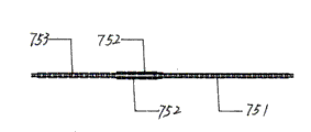
Fig. 2 is chain discharge structure figure of the present invention.
Fig. 3 steps on the scheme drawing that moves ahead under the right crus of diaphragm of the present invention.
Fig. 4 steps on the scheme drawing that moves ahead down again for left foot of the present invention.
Fig. 5 is folding effect figure of the present invention.
Among the figure: 1---vehicle body, 2---front fork, 3---the folding grip standpipe, 4---handlebar, 5---front-wheel, 6---trailing wheel, 7---driver train, 8---brake; Wherein vehicle body 1 also comprises: 11---the car beam, and 12---the front pipe, 13---back vent, 14---fix shaft, 15---rear panel, 16---middle panel; Folding grip standpipe 3 also comprises: 31---folding part down, and 32---handle riser; Driver train 7 also comprises: 71---treadle, and 72---pedal, 73---stick up bar, 74---movable pulley, 75---chain, 76---extension spring, 77---flywheel, 78---connecting strap; Wherein chain 75 also comprises: 751---preceding cutter chain bar, and 752---middle cutter chain bar, 753---back cutter chain bar; Brake 8 also comprises: 81---brake lever, and 82---the line of stopping, 83---the sheet of stopping.
The specific embodiment
According to Fig. 1, Fig. 2, Fig. 3, described folding movable pulley driven scooter comprises vehicle body 1, front fork 2, folding grip standpipe 3, handlebar 4, front-wheel 5, trailing wheel 6, driver train 7 and brakes 8;
Described vehicle body 1 comprises car beam 11, front pipe 12, back vent 13, fix shaft 14, rear panel 15 and middle panel 16; Described car beam 11 is to bend to arc metal tube; Described car beam 11 front ends connect described front pipe 12; Described car beam 11 rear ends connect described back vent 13, and also to wearing and weld a described fix shaft 14, the top at said car beam 11 rear portions connects described rear panel 14 in the front portion of said car beam 11; The top at said car beam 11 middle parts connects described middle panel 15, and described rear panel 14 all is a plastic front board with described middle panel 15.
Described front fork 2 is rotatably connected through seven bowls and described front pipe 12, and described front-wheel 5 is installed on the described front fork 2, and described trailing wheel 6 is installed on the described back vent 13;
Described folding grip standpipe 3 comprises folding part 31 and handle riser 32 down; The described folding part 31 down of
Figure 991488DEST_PATH_IMAGE002
Figure 70302DEST_PATH_IMAGE002
is that a sheetmetal strikes out the U-shaped bending; The middle part and the bottom on said U-shaped curved openings both sides; A pair of perforation is respectively arranged; Said folding part 31U shape curved top portion down has a U-shaped gap; The bottom of part 31 is to boring a hole through the front fork tube of lock bolt and said front fork 2 is made amplexis under said the folding, and the middle part of part 31 is to boring a hole through being rotatably connected to locking bolt and described handle riser 32 under said the folding;
A thick-walled metal pipe is welded in the bottom of described handle riser 32; Said handle riser 32 is through the middle part of the thick-walled metal pipe of bottom and said folding part 31 down perforation to be done to be rotatably connected; The bottom of said handle riser 32 also has a flange to perforation; The flange of said handle riser 32 has a slotted hole to the vertical position of perforation, and the flange of said handle riser 32 is to being placed with a cylinder with threaded hole in the perforation, and the slotted hole of said handle riser 32 is corresponding with the said folding U-shaped gap at part 31 tops that descends; One band is penetrated bolt the slotted hole of said handle riser 32; Be screwed in the tapped bore of said cylinder again, just can described handle riser 32 and described folding part 31 be down made interlocking, described handlebar 4 is installed on the described handle riser 32.
Described driver train 7; Comprise treadle 71, pedal 72, stick up bar 73, movable pulley 74, chain 75, extension spring 76, flywheel 77 and connecting strap 78; Described driver train 7 is the both sides that are arranged on said car beam about two covers divide; Described treadle 71 is the vertical thick-walled pipes that respectively weld in a pipe front and back end, has attacked screw thread in the heavy wall pore of said treadle 71 rear ends, the rotatable two, the left and right sides that is socketed on said fix shaft of the front end of two said treadles 71; Two described pedals 72 are installed on the rear end of said two treadles, and a described bar 73 that sticks up is also respectively welded in the below of two said treadle 71 front ends;
Two said bottoms of the sticking up bar 73 described movable pulley 74 that respectively is rotatably connected, described movable pulley 74 is plastic pulleys of bead trough of belt, is installed on the two said flywheels 77 of said trailing wheel 6 the right and lefts, is two to cooperate the small flywheel of PU wheel;
On two described chain 75 solderless wrapped connections and two described movable pulleys 74 and the two described flywheels 77; Two described chains 75 also comprise preceding cutter chain bar 751, middle cutter chain bar 752 and back cutter chain bar 753, described in cutter chain bar 752 be two side by side, front and back end and preceding cutter chain bar 751 with after cutter chain bar 753 bonded assembly chains; In the unmanned masterpiece time spent; The both sides of two said flywheel 77 gear teeth about two described middle cutter chain bars 752 are wire-wrapped in, flywheel 77 front and back of this moment can accessiblely be rotated, when trampling described pedal 72; Describedly stick up before sticking up bar 73; Draw before the said chain 75 of inconjunction with, the gear teeth of the said flywheel 77 of this moment are changeed forward by cutter chain bar 753 solderless wrapped connections of described back and band, and car is moved ahead fast.
One end of said extension spring 76 connects described back cutter chain bar 753; The other end is connected in described connecting strap 78; It is the parts that are welded in both sides, said car beam 11 middle part that the front end of said preceding cutter chain bar 751 is connected in described connecting strap 78, two described connecting straps 78, and button is detained with the back before having on the described connecting strap 78; The preceding button of said connecting strap 78 is connected with described preceding cutter chain bar 751 through pin, and the back button of said connecting strap 78 is used for the described extension spring 76 of clasp joint.
Described brake 8 comprises brake lever 81, the stop line 82 and the sheet 83 of stopping; Said brake lever 81 is installed on the described handlebar 4; The described line 82 of stopping is connected with described brake lever 81; The described sheet 83 stopped is rotatable be installed on the described front fork 2 with described back vent 13 on, the front end of the said sheet 83 of stopping is connected with the described line 82 of stopping, there is retracing spring said sheet 83 and the said junction of stopping line 82 of stopping.

Claims (8)

1. folding two movable pulleys drive bicycle; Comprise vehicle body, front fork, folding grip standpipe, handlebar, front-wheel, trailing wheel, driver train and brake; It is characterized in that: vehicle body is made up of car beam, front pipe, back vent, fix shaft, rear panel and middle panel; The folding grip standpipe is made up of folding part down and handle riser; Brake is made up of brake lever, stop line and the sheet of stopping, driver train by treadle, pedal, stick up bar, movable pulley, chain, extension spring, flywheel and connecting strap and constitute, driver train is the both sides that are arranged on the car beam about two covers divide; Car beam archwise, the Che Liang rear end connects back vent, and the front portion of car beam is connected with fix shaft, two socket two treadles of fix shaft; The front pipe of car beam front end connects front fork, and front-wheel is arranged on the front fork, and front fork connects the folding grip standpipe; Handlebar is installed on the folding grip standpipe, and two treadles connect two and stick up bar, and two stick up bar connects two movable pulleys; Back vent connects trailing wheel, and trailing wheel connects two flywheels, and two chains are wire-wrapped on two movable pulleys and two flywheels; Two chains link two springs, and two springs connect two connecting straps, and two connecting straps connect two chains.
2. folding two movable pulleys according to claim 1 drive bicycle; It is characterized in that: the front portion of said car beam is to wearing and weld a described fix shaft; The top at said Che Liang rear portion connects described rear panel; The top at said car beam middle part connects described middle panel, and described rear panel and described middle panel all are plastic front board.
3. folding two movable pulleys according to claim 1 drive bicycle; It is characterized in that: described folding grip standpipe comprises folding part and handle riser down; The described folding part down of
Figure 2011102506781100001DEST_PATH_IMAGE002
is that a sheetmetal strikes out the U-shaped bending; The middle part and the bottom on said U-shaped curved openings both sides; A pair of perforation is respectively arranged; Said folding part U-shaped curved top portion down has a U-shaped gap; The bottom of part is to boring a hole through the front fork tube of lock bolt and said front fork is made amplexis under said the folding, and the middle part of part is to boring a hole through being rotatably connected to locking bolt and described handle riser under said the folding.
4. folding two movable pulleys according to claim 1 drive bicycle; It is characterized in that: a thick-walled metal pipe is welded in the bottom of described handle riser; Said handle riser is through the middle part of the thick-walled metal pipe of bottom and said folding part down perforation to be done to be rotatably connected; The bottom of said handle riser also has a flange to perforation, and the flange of said handle riser has a slotted hole to the vertical position of perforation, and the flange of said handle riser is to being placed with a cylinder with threaded hole in the perforation; The slotted hole of said handle riser is corresponding with the U-shaped gap at said folding part top down; One band is penetrated the slotted hole of said handle riser to bolt, be screwed into again in the tapped bore of said cylinder, just can described handle riser and the described time part that folds be made interlocking.
5. folding two movable pulleys according to claim 1 drive bicycle; It is characterized in that: described driver train is the both sides that are arranged on said car beam about two covers divide; Described treadle is the vertical thick-walled pipe that respectively welds in a pipe front and back end; Attacked screw thread in the heavy wall pore of said treadle rear end; The rotatable two, the left and right sides that is socketed on said fix shaft of the front end of two said treadles, two described pedals are installed on the rear end of said two treadles, and a described bar that sticks up is also respectively welded in the below of two said treadle front ends.
6. folding two movable pulleys according to claim 1 drive bicycle; It is characterized in that: two said bottoms of the sticking up bar described movable pulley that respectively is rotatably connected; Described movable pulley is the plastic pulley of bead trough of belt; Being installed on the two said flywheels of said trailing wheel the right and left, is the small flywheel of two cooperation PU wheels.
7. folding two movable pulleys according to claim 1 drive bicycle; It is characterized in that: on two described chain solderless wrapped connections and two described movable pulleys and the two described flywheels; Two described chains also comprise preceding cutter chain bar, middle cutter chain bar and back cutter chain bar; In described the cutter chain bar be two side by side, front and back end and preceding cutter chain bar and back cutter chain bar bonded assembly chain.
8. folding two movable pulleys according to claim 1 drive bicycle; It is characterized in that: an end of said extension spring connects described back cutter chain bar; The other end is connected in described connecting strap; The front end of cutter chain bar is connected in described connecting strap before said, and two described connecting straps are the parts that are welded in both sides, said car beam middle part, button and back button before having on the described connecting strap; The preceding button of said connecting strap is connected with described preceding cutter chain bar through pin, and the back button of said connecting strap is used for the described extension spring of clasp joint.
CN 201110250678 2011-08-29 2011-08-29 Folding dual-movable pulley driven vertical riding vehicle Expired - Fee Related CN102351023B (en)

Priority Applications (1)

Application Number Priority Date Filing Date Title
CN 201110250678 CN102351023B (en) 2011-08-29 2011-08-29 Folding dual-movable pulley driven vertical riding vehicle

Applications Claiming Priority (1)

Application Number Priority Date Filing Date Title
CN 201110250678 CN102351023B (en) 2011-08-29 2011-08-29 Folding dual-movable pulley driven vertical riding vehicle

Publications (2)

Publication Number Publication Date
CN102351023A true CN102351023A (en) 2012-02-15
CN102351023B CN102351023B (en) 2013-09-04

Family

ID=45574712

Family Applications (1)

Application Number Title Priority Date Filing Date
CN 201110250678 Expired - Fee Related CN102351023B (en) 2011-08-29 2011-08-29 Folding dual-movable pulley driven vertical riding vehicle

Country Status (1)

Country Link
CN (1) CN102351023B (en)

Cited By (1)

* Cited by examiner, † Cited by third party
Publication number Priority date Publication date Assignee Title
CN103738452A (en) * 2014-01-21 2014-04-23 赵洪亮 Tilted rod driving mechanism

Citations (5)

* Cited by examiner, † Cited by third party
Publication number Priority date Publication date Assignee Title
CN2079152U (en) * 1990-06-12 1991-06-19 威海波 Tricycle child cart
NL9200864A (en) * 1992-05-15 1993-12-01 Paul Siebe Poelstra Portable motor vehicle
DE10100697A1 (en) * 2001-01-10 2001-07-26 Ludwig Kefer Scooter with tread board couples board to wheel bearing via gear housing complete with pedal crank and return spring and with board rising to freewheel hub at rear
JP2002058778A (en) * 2000-08-21 2002-02-26 Taichi Nishio Drive device for skater type vehicle
CN202283968U (en) * 2011-08-29 2012-06-27 太仓市车中宝休闲用品有限公司 Foldable double movable-pulley driven vertical bike

Patent Citations (5)

* Cited by examiner, † Cited by third party
Publication number Priority date Publication date Assignee Title
CN2079152U (en) * 1990-06-12 1991-06-19 威海波 Tricycle child cart
NL9200864A (en) * 1992-05-15 1993-12-01 Paul Siebe Poelstra Portable motor vehicle
JP2002058778A (en) * 2000-08-21 2002-02-26 Taichi Nishio Drive device for skater type vehicle
DE10100697A1 (en) * 2001-01-10 2001-07-26 Ludwig Kefer Scooter with tread board couples board to wheel bearing via gear housing complete with pedal crank and return spring and with board rising to freewheel hub at rear
CN202283968U (en) * 2011-08-29 2012-06-27 太仓市车中宝休闲用品有限公司 Foldable double movable-pulley driven vertical bike

Cited By (1)

* Cited by examiner, † Cited by third party
Publication number Priority date Publication date Assignee Title
CN103738452A (en) * 2014-01-21 2014-04-23 赵洪亮 Tilted rod driving mechanism

Also Published As

Publication number Publication date
CN102351023B (en) 2013-09-04

Similar Documents

Publication Publication Date Title
KR101780164B1 (en) Compact, Foldable Bicycle
US9073600B2 (en) Dual drive bicycle
US7967314B1 (en) Wheeled vehicle drive mechanism with hand lever arm
CN102351025B (en) Folding dual movable pulley-driven tricycle capable of running uprightly
CN202295156U (en) Foldable three-wheel vertical driving vehicle driven by double movable pulleys
CN102351023B (en) Folding dual-movable pulley driven vertical riding vehicle
CN202283968U (en) Foldable double movable-pulley driven vertical bike
US20060125205A1 (en) Front wheel drive mechanism for bicycle
CN101342928A (en) Ratchet type bicycle driver
CN102351024B (en) Folded movable-pulley driving type scooter
CN202414060U (en) Pendulum type three-wheel scooter
CN101580093B (en) Front driving wheel four-wheel step-slide car
CN102442393A (en) Pedal scooter
CN202283967U (en) Foldable movable pulley driven type scooter
CN203078684U (en) Six-joining-beam folding portable bicycle
CN211167269U (en) Double-drive transfer bicycle
CN101585393A (en) Fork bevel pulley oscillating bar bicycle
CN102267523A (en) Seat-pipe rotary shaft type single-fork folding bicycle
CN202046405U (en) Three-point horizontal bicycle
CA2588303A1 (en) Swing powered scooter
CN103661754A (en) Two-wheeled hand-cranking bicycle
CN103935440B (en) Vehicle body vehicle seat six-bar linkage fast folding portable electric bicycle
CN201447007U (en) Unequal wheel diameter double rail spring bicycle
CN202063223U (en) Single-fork folding bicycle with rotary shaft type seat tube
CN203211449U (en) Quick foldable pushable portable bicycle

Legal Events

Date Code Title Description
C06 Publication
PB01 Publication
C10 Entry into substantive examination
SE01 Entry into force of request for substantive examination
C14 Grant of patent or utility model
GR01 Patent grant
TR01 Transfer of patent right

Effective date of registration: 20170627

Address after: 015400, No. 5, No. 27, Shengli village, three Qiao Town, Bayannaoer, the Inner Mongolia Autonomous Region, Hangjinhouqi

Patentee after: Ma Hongling

Address before: 215421 Jiangsu city of Suzhou province Taicang city Shaxi Songnan Industrial Park

Co-patentee before: Pang Mingfang

Patentee before: Taicang Chezhongbao Leisure Articles Co., Ltd.

CP02 Change in the address of a patent holder

Address after: 266700 Gaoping Road, Polygonum Town, Pingdu City, Qingdao, Shandong Province, No. 58

Patentee after: Ma Hongling

Address before: 015400, No. 5, No. 27, Shengli village, three Qiao Town, Bayannaoer, the Inner Mongolia Autonomous Region, Hangjinhouqi

Patentee before: Ma Hongling

CF01 Termination of patent right due to non-payment of annual fee

Granted publication date: 20130904

Termination date: 20180829