CN102290744A - Live-line large knife clip replacement tool for 1,000mm<2> conducting wire - Google Patents
Live-line large knife clip replacement tool for 1,000mm<2> conducting wire Download PDFInfo
- Publication number
- CN102290744A CN102290744A CN2011102528066A CN201110252806A CN102290744A CN 102290744 A CN102290744 A CN 102290744A CN 2011102528066 A CN2011102528066 A CN 2011102528066A CN 201110252806 A CN201110252806 A CN 201110252806A CN 102290744 A CN102290744 A CN 102290744A
- Authority
- CN
- China
- Prior art keywords
- housing
- shaped
- gear
- gone
- rod
- Prior art date
- Legal status (The legal status is an assumption and is not a legal conclusion. Google has not performed a legal analysis and makes no representation as to the accuracy of the status listed.)
- Granted
Links
Images




Landscapes
- Electric Cable Installation (AREA)
Abstract
本发明公开了一种1000平方毫米导线用带电作业大刀卡更换工具,包括行走机构,行走机构的壳体背部安装横移机构,横移机构的横向移动座上安装旋转机构,旋转机构的大齿轮上安装调整机构,调整机构的转动杆的前端安装翻动铰连座,翻动铰连座通过连接板与U形线夹连接,U形线夹上设有限位槽,U形线夹的与液压缸铰接,液压缸的活塞杆与绝缘杆固定连接,绝缘杆与大刀卡线夹的一端铰接,大刀卡线夹的另一端设有定位钩,翻动铰连座上安装翻转驱动电机;U形线夹上安装两个Z形夹板,两Z形夹板的中部通过中轴铰接,中轴与U形线夹连接固定,两Z形夹板的下部位于限位槽两侧,两Z形夹板的上端之间安装电动推杆。

The invention discloses a large tool card replacement tool for 1000 square millimeter wires for live work, which includes a traveling mechanism, a lateral movement mechanism is installed on the back of the casing of the traveling mechanism, a rotary mechanism is installed on the lateral movement seat of the lateral movement mechanism, and a large gear of the rotary mechanism The adjustment mechanism is installed on the top, and the front end of the rotating rod of the adjustment mechanism is installed with a flipping hinge seat. The flipping hinge seat is connected with the U-shaped wire clamp through the connecting plate. Hinged, the piston rod of the hydraulic cylinder is fixedly connected with the insulating rod, the insulating rod is hinged with one end of the big knife clamp, the other end of the big knife clamp is provided with a positioning hook, and the flip drive motor is installed on the flip hinge seat; U-shaped clamp Two Z-shaped splints are installed on the top, the middle parts of the two Z-shaped splints are hinged through the central axis, and the central axis is connected and fixed with the U-shaped clamp. Install the electric push rod.
Description
技术领域 technical field
本发明涉及一种1000平方毫米导线用带电作业大刀卡更换工具。 The invention relates to a tool for replacing a large knife card for live working with a wire of 1000 square millimeters.
背景技术 Background technique
目前,在超高压输变电行业,利用现有工具带电更换线路双L串绝缘子、双V串绝缘子的过程中存在较大的安全隐患。其主要原因是:利用现有的工具更换绝缘子串需要至少两名工作人员配合完成,而且,由于绝缘子的安装位置是一端靠近架线用铁塔,另一端安装远离架线用铁塔,因此,至少有一名工作人员要在完全离开架线铁塔,整个身体悬挂于输电线路上的情况下进行高空作业,作业安全性较低,易发生输电线路断裂,造成人员高坠落伤亡的事故。目前需要一种可替代工作人员高空作业的更换工具,但要实现更换工具自动与绝缘子连接,并自动锁定绝缘子始终是一个难题。 At present, in the ultra-high voltage power transmission and transformation industry, there are great potential safety hazards in the process of using existing tools to replace double L series insulators and double V series insulators. The main reason is that it needs at least two workers to cooperate to replace the insulator string with the existing tools, and, because the installation position of the insulator is that one end of the insulator is close to the wire tower, and the other end is installed away from the wire tower, therefore, at least one A staff member must leave the wire tower completely and carry out high-altitude operations under the condition that the whole body is suspended on the transmission line. The safety of the operation is low, and the transmission line is prone to breakage, causing accidents of high falls and casualties. At present, there is a need for a replacement tool that can replace workers working at heights, but it is always a difficult problem to realize the automatic connection of the replacement tool with the insulator and the automatic locking of the insulator.
发明内容 Contents of the invention
本发明的目的,是提供一种1000平方毫米导线用带电作业大刀卡更换工具,它可在输电线路上自由移动,能辅助工作人员完成带电更换绝缘子的工作,从而可避免工作人员悬挂于输电线路上高空作业,可从根本上杜绝因输电线路断裂而造成人员坠落伤亡的事故发生。并且,它可实现与绝缘子自动连接并锁定,可完全替代人工进行高空作业。 The object of the present invention is to provide a tool for changing the live working knife card for 1000 square millimeter wires, which can move freely on the transmission line, and can assist the staff to complete the work of live insulator replacement, thereby preventing the staff from hanging on the transmission line Working at heights can fundamentally prevent the accidents of personnel falling and causing casualties due to the breakage of power transmission lines. Moreover, it can be automatically connected and locked with the insulator, which can completely replace manual high-altitude operations.
本发明的目的是通过以下技术方案实现的:1000平方毫米导线用带电作业大刀卡更换工具,包括壳体,壳体内开设内腔,内腔的上部固定安装四根第一缓冲杆,每根第一缓冲杆的第一导向杆伸出壳体外安装行走电机,行走电机的输出轴上安装行走槽轮,行走槽轮位于壳体的前上方;壳体的背部安装导轨和横移驱动丝杠,横移驱动丝杠能相对壳体旋转,导轨上安装横向移动座,横向移动座能沿导轨直线移动,横向移动座上安装横移驱动螺母,横移驱动螺母与横移驱动丝杠螺纹连接,横移驱动丝杠位于横向移动座的内侧,壳体上安装横移驱动电机,横移驱动电机的输出轴与横移驱动丝杠的一端连接,横向移动座上安装大齿轮,大齿轮的轴垂直于壳体的背面,壳体上安装小齿轮、变速器和旋转驱动电机,小齿轮与大齿轮啮合,小齿轮的轴与变速器的输出轴连接,变速器的输入轴与旋转驱动电机的输出轴连接,大齿轮上安装摆臂,摆臂内安装转动杆,转动杆能相对摆臂旋转,摆臂的后端安装调整驱动电机,调整驱动电机的输出轴与转动杆的后端连接,转动杆的前端安装翻动铰连座,翻动铰连座位于摆臂外,翻动铰连座与连接板铰接,连接板上安装U形线夹,U形线夹上设有限位槽,U形线夹的与液压缸铰接,液压缸的活塞杆与绝缘杆固定连接,绝缘杆与大刀卡线夹的一端铰接,大刀卡线夹的另一端设有定位钩,大刀卡线夹的侧壁上开设三个定位螺孔,翻动铰连座上安装翻转驱动电机,翻转驱动电机的输出轴与翻动铰连座和连接板的铰连轴连接;U形线夹上安装第一Z形夹板和第二Z形夹板,第一Z形夹板和第二Z形夹板的中部通过中轴铰接,中轴与U形线夹连接固定,第一Z形夹板和第二Z形夹板的下部位于限位槽两侧,第一Z形夹板和第二Z形夹板的上端之间安装电动推杆,电动推杆与第二Z形夹板的上端铰接,电动推杆的推杆与第一Z形夹板的上端铰接。 The purpose of the present invention is achieved through the following technical solutions: 1000 square millimeters of wires are used for live working large knife card replacement tools, including a housing, an inner chamber is provided in the housing, and four first buffer rods are fixedly installed on the upper part of the inner chamber. The first guide rod of a buffer rod protrudes out of the casing to install the traveling motor, and the output shaft of the traveling motor is installed with a traveling sheave, which is located at the front and upper part of the casing; The traversing drive screw can rotate relative to the shell, and the traversing movement seat is installed on the guide rail, and the traversing movement seat can move linearly along the guide rail. The traversing drive screw is located on the inner side of the traversing seat, and the traversing drive motor is installed on the housing. The output shaft of the traversing drive motor is connected to one end of the traversing drive screw. The large gear is installed on the traversing seat, and the shaft of the large gear Perpendicular to the back of the housing, a pinion, a transmission and a rotary drive motor are installed on the housing, the pinion is meshed with the large gear, the shaft of the pinion is connected to the output shaft of the transmission, and the input shaft of the transmission is connected to the output shaft of the rotary drive motor , a swing arm is installed on the large gear, and a rotating rod is installed in the swing arm. The rotating rod can rotate relative to the swing arm. The rear end of the swing arm is equipped with an adjustment drive motor. The flip hinge seat is installed on the front end, the flip hinge seat is located outside the swing arm, the flip hinge seat is hinged with the connecting plate, the U-shaped wire clip is installed on the connecting plate, and the U-shaped wire clip is provided with a limit groove, and the U-shaped wire clip and the The hydraulic cylinder is hinged, the piston rod of the hydraulic cylinder is fixedly connected with the insulating rod, the insulating rod is hinged with one end of the big knife clamp, the other end of the big knife clamp is provided with a positioning hook, and the side wall of the big knife clamp is provided with three positioning Screw hole, install the turning drive motor on the turning hinge seat, the output shaft of the turning driving motor is connected with the hinge shaft of the turning hinge seat and the connecting plate; install the first Z-shaped splint and the second Z-shaped splint on the U-shaped clamp , the middle parts of the first Z-shaped splint and the second Z-shaped splint are hinged through the central axis, and the central axis is connected and fixed with the U-shaped clamp. The lower parts of the first Z-shaped splint and the second Z-shaped splint are located on both sides of the limiting groove. An electric push rod is installed between the upper end of a Z-shaped splint and the second Z-shaped splint, the electric push rod is hinged with the upper end of the second Z-shaped splint, and the push rod of the electric push rod is hinged with the upper end of the first Z-shaped splint.
为进一步实现本发明的目的,还可以采用以下技术方案实现:内腔的下部以内腔中轴线为中线左右对称安装两个跨越障碍支架,跨越障碍支架由U形支座、连杆、支撑座、第二缓冲杆、跨越辊支架和跨越辊连接构成;U形支座竖直安装于内腔内,U形支座与壳体固定连接,U形支座上安装转轴,转轴的两端各安装一根连杆,连杆的后端与转轴固定连接,连杆的前端分别与支撑座的两端铰接,支撑座上安装第二缓冲杆,第二缓冲杆的第二导向杆大齿轮穿过支撑座安装跨越辊支架,跨越辊支架上安装跨越辊;壳体的左右两侧各开设一个凹槽,凹槽与跨越障碍支架对应;内腔内安装控制箱,控制箱上安装第一电机,第一电机的输出轴上安装第一链轮和第二齿轮,左侧跨越障碍支架的转轴的上端安装第二链轮,第二链轮与第一链轮通过第一链条连接;内腔内安装第三齿轮,第三齿轮与第二齿轮啮合,第三齿轮的轴上安装第四链轮,右侧跨越障碍支架的转轴的上端安装第三链轮,第三链轮通过第二链条与第四链轮连接;壳体的上部安装安装杆,安装杆上安装摄像转动盘,摄像转动盘上安装摄像铰链座,摄像铰链座上安装摄像头;壳体的一侧安装机械手臂绝缘杆绝缘杆,机械手臂绝缘杆绝缘杆位于内腔内,壳体与机械手臂绝缘杆绝缘杆对应的侧壁上开设便于机械手臂绝缘杆绝缘杆伸出的透孔。所述行走槽轮的轴上设有定位杆,内腔内安装限位槽轮铰链座,限位槽轮铰链座与壳体的上部内壁固定连接,限位槽轮铰链座上安装转动轴,转动轴与定位杆空间垂直,转动轴上安装杠杆和第一齿轮,杠杆上安装限位槽轮,限位槽轮的轴上安装限位板,限位板与第一缓冲杆的轴空间垂直;第三齿轮的轴上安装第一丝杠,第一丝杠的外周安装第二螺母,第二螺母上安装齿条和滑套,内腔内固定安装滑轨,滑轨与滑套配合,齿条与第一齿轮啮合,限位板上开设定位槽,定位槽与定位杆一一对应。所述内腔内平行设有两块定位隔板,控制箱和第一电机位于两定位隔板之间。所述左侧跨越障碍支架的转轴下端和右侧跨越障碍支架的转轴的下端分别穿出壳体外各安装一个配重块;两配重块相对应的一端都是圆弧面。所述的第一缓冲杆包括第一缓冲杆壳体,第一缓冲杆壳体的侧壁上开设第一透槽,第一缓冲杆壳体内安装第一导向杆,第一导向杆的外周设有第一限位凸块,第一限位凸块上设有第一限位杆,第一限位杆位于第一透槽内,第一导向杆的外周安第一弹簧,第一弹簧的一端与第一限位凸块接触,第一弹簧的另一端与第一缓冲杆壳体的前端接触。所述的第二缓冲杆包括第二缓冲杆壳体,第二缓冲杆壳体的侧壁上开设第二透槽,第二缓冲杆壳体内安装第二导向杆,第二导向杆的外周设有第二限位凸块,第二限位凸块上设有第二限位杆,第二限位杆与第二透槽配合,第二导向杆的外周安装第二弹簧,第二弹簧的一端与第二限位凸块接触,第二弹簧的另一端与第二缓冲杆壳体接触。第一Z形夹板和第二Z形夹板的内侧各设有一根齿条。U形线夹内开设圆弧形槽,圆弧形槽的两端口分别位于限位槽的两侧,圆弧形槽内安装圆弧形锁杆,圆弧形锁杆的后半段内侧设有弧形齿条;U形线夹内开设齿轮槽,齿轮槽与圆弧形槽相通,齿轮槽内安装第四齿轮,第四齿轮与弧形齿条啮合;U形线夹上安装第二电机,第二电机的输出轴穿入齿轮槽内与第四齿轮的轴连接。 In order to further realize the purpose of the present invention, the following technical solutions can also be adopted to realize: the bottom of the inner chamber takes the central axis of the inner cavity as the midline and installs two crossing obstacle brackets symmetrically, and the crossing obstacle bracket is composed of U-shaped bearings, connecting rods, support seats, The second buffer bar, the spanning roller bracket and the spanning roller are connected; the U-shaped support is installed vertically in the inner cavity, and the U-shaped support is fixedly connected with the housing. A connecting rod, the rear end of the connecting rod is fixedly connected with the rotating shaft, the front end of the connecting rod is respectively hinged with the two ends of the support seat, the second buffer rod is installed on the support seat, and the second guide rod of the second buffer rod passes through the large gear The support seat is installed with a spanning roller bracket, and the spanning roller is installed on the spanning roller bracket; a groove is provided on the left and right sides of the housing, and the groove corresponds to the spanning obstacle bracket; a control box is installed in the inner cavity, and the first motor is installed on the control box. A first sprocket and a second gear are installed on the output shaft of the first motor, and a second sprocket is installed on the upper end of the rotating shaft of the left side straddling the obstacle bracket, and the second sprocket is connected with the first sprocket through the first chain; The third gear is installed, the third gear meshes with the second gear, the fourth sprocket is installed on the shaft of the third gear, the third sprocket is installed on the upper end of the rotating shaft of the right side across the obstacle support, and the third sprocket is connected to the second chain by the second chain. The fourth sprocket is connected; the upper part of the housing is installed with a mounting rod, and the camera rotating disc is installed on the mounting rod, and the camera hinge seat is installed on the camera rotating disc, and the camera is installed on the camera hinge seat; one side of the housing is installed with a mechanical arm insulating rod and an insulating rod , the insulating rod of the mechanical arm insulating rod is located in the inner cavity, and the housing and the corresponding side wall of the insulating rod of the mechanical arm insulating rod are provided with through holes to facilitate the stretching out of the insulating rod of the mechanical arm insulating rod. The shaft of the walking sheave is provided with a positioning rod, and a limit sheave hinge seat is installed in the inner cavity, and the limit sheave hinge seat is fixedly connected with the upper inner wall of the housing, and a rotating shaft is installed on the limit sheave hinge seat. The rotating shaft is perpendicular to the space of the positioning rod, the lever and the first gear are installed on the rotating shaft, the limit sheave is installed on the lever, the limit plate is installed on the axis of the limit sheave, and the limit plate is perpendicular to the axis space of the first buffer rod The first lead screw is installed on the shaft of the third gear, the second nut is installed on the periphery of the first lead screw, the rack and the sliding sleeve are installed on the second nut, the slide rail is fixedly installed in the inner cavity, and the slide rail cooperates with the slide sleeve, The rack meshes with the first gear, and positioning grooves are provided on the limiting plate, and the positioning grooves correspond to the positioning rods one by one. Two positioning partitions are arranged in parallel in the inner cavity, and the control box and the first motor are located between the two positioning partitions. The lower ends of the rotating shafts of the left side crossing the obstacle support and the right side crossing the obstacle support respectively pass through the housing and install a counterweight; the corresponding ends of the two counterweights are arc surfaces. The first buffer rod includes a first buffer rod housing, a first through groove is provided on the side wall of the first buffer rod housing, a first guide rod is installed in the first buffer rod housing, and the outer periphery of the first guide rod is provided with There is a first limit bump, and a first limit rod is arranged on the first limit bump, and the first limit rod is located in the first through groove. The outer periphery of the first guide rod is equipped with a first spring, and the first spring One end is in contact with the first limiting projection, and the other end of the first spring is in contact with the front end of the first buffer rod housing. The second buffer rod includes a second buffer rod housing, a second through groove is provided on the side wall of the second buffer rod housing, a second guide rod is installed in the second buffer rod housing, and the outer periphery of the second guide rod is provided with There is a second limit projection, the second limit projection is provided with a second limit rod, the second limit rod cooperates with the second through groove, the outer circumference of the second guide rod is equipped with a second spring, and the second spring One end is in contact with the second limiting projection, and the other end of the second spring is in contact with the second buffer rod housing. The inner sides of the first Z-shaped splint and the second Z-shaped splint are respectively provided with a rack. An arc-shaped groove is provided in the U-shaped wire clamp, and the two ports of the arc-shaped groove are respectively located on both sides of the limit groove. There is an arc-shaped rack; a gear groove is set in the U-shaped clamp, and the gear groove communicates with the arc-shaped groove. The fourth gear is installed in the gear groove, and the fourth gear meshes with the arc-shaped rack; the second gear is installed on the U-shaped clamp. motor, the output shaft of the second motor passes through the gear groove and is connected with the shaft of the fourth gear.
本发明的积极效果在于:它可快速稳定地跨越架空线路上的间隔棒和防振锤,能轻松穿过直线杆塔,在架空线路上几乎不存在对其造成阻碍的物件,可真正实现在整个架空线路上自由移动,便于推广应用,完全有能力替代人工完成悬挂于输电线路上的更换绝缘子的辅助工作,具有安全高效的优点。它不仅操作使用安全方便,还具有悬挂方便的优点。在悬挂时,它的跨越障碍支架可折叠收入更换绝缘子工具壳体内,它的更换绝缘子工具及更换绝缘子工具的定位装置可折叠收于壳体后部,使更换绝缘子工具外部除行走轮和摄像头外几乎没有分支机构,而行走轮和摄像头在悬挂过程中均高于所有架空线路,不会发生缠绕,从而,可有效防止在悬挂所述更换绝缘子工具时,其跨越障碍支架与线路缠绕,避免出现既无法正常悬挂所述更换绝缘子工具,又无法取下的情况。在更换绝缘子工具悬挂完成后,更换绝缘子工具可自行展开,以便在线路上稳定行走。本发明还具有结构简洁紧凑、制造成本低廉和操作方便的优点。 The positive effect of the present invention is that it can quickly and stably cross the spacer rods and anti-vibration hammers on the overhead line, and can easily pass through the straight pole tower. It is free to move on the overhead line, easy to popularize and apply, fully capable of replacing the auxiliary work of replacing insulators suspended on the transmission line by hand, and has the advantages of safety and high efficiency. It is not only safe and convenient to operate, but also has the advantage of convenient hanging. When hanging, its barrier-crossing bracket can be folded into the housing of the replacement insulator tool, and its replacement insulator tool and its positioning device can be folded and stored in the rear of the housing, so that the outside of the replacement insulator tool except the traveling wheels and camera There are almost no branches, and the traveling wheels and the camera are higher than all overhead lines during the suspension process, and no entanglement will occur. Therefore, it can effectively prevent the entanglement between the obstacle bracket and the line when the replacement insulator tool is suspended, avoiding the occurrence of The condition that the replacement insulator tool can neither be hung normally nor removed. After the suspension of the replacement insulator tool is completed, the replacement insulator tool can be unfolded by itself for stable walking on the line. The invention also has the advantages of simple and compact structure, low manufacturing cost and convenient operation.
附图说明 Description of drawings
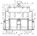
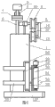
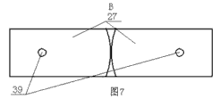
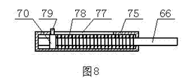
图1是本发明所述1000平方毫米导线用带电作业大刀卡更换工具的结构示意图;图2是图1的后视结构示意图,图中省略了更换绝缘子工具;图3是本发明所述1000平方毫米导线用带电作业大刀卡更换工具展后开处于工作状态的结构示意图,图中省略了更换绝缘子工具;图4是图3的C向结构示意图;图5是图2的A-A剖视结构示意图;图6是图3的左视结构示意图;图7是图2的B向结构示意图;图8是所述第一缓冲杆的结构示意图;图9是图所示第二缓冲杆的结构示意图;图10是图1的D向放大的结构示意图;图11是图1的E向放大结构示意图。 Fig. 1 is the structural representation of 1000 square millimeter wires described in the present invention with live work big knife card replacement tool; Fig. 2 is the rear view structural representation of Fig. 1, has omitted the replacement insulator tool among the figure; Fig. 3 is 1000 square millimeters described in the present invention The structure schematic diagram of the large knife card replacement tool for the millimeter wire used for live work is unfolded and in the working state, and the insulator replacement tool is omitted in the figure; Figure 4 is a structural schematic diagram of the C direction of Figure 3; Figure 5 is a schematic diagram of the A-A sectional structure of Figure 2; Fig. 6 is a schematic diagram of the left view of Fig. 3; Fig. 7 is a schematic diagram of the structure of Fig. 2 to B; Fig. 8 is a schematic diagram of the structure of the first buffer rod; Fig. 9 is a schematic diagram of the structure of the second buffer rod shown in the figure; Fig. 10 is a schematic diagram of the enlarged structure along the direction D of FIG. 1; FIG. 11 is a schematic diagram of the enlarged structure along the direction E of FIG. 1.
附图标记:1壳体 2内腔 3第一缓冲杆 4行走槽轮 5定位杆 6安装杆 7摄像转动盘 8摄像铰链座 9摄像头 10限位槽轮铰链座 11杠杆 12第一齿轮 13限位槽轮 14限位板 15定位槽 16第一链轮 17第二链轮 18第一链条 19第三链轮 20第二链条 21第四链轮 22第二齿轮 23第三齿轮 24第一电机 25控制箱 26定位隔板 27配重块 28跨越障碍支架 29辅助辊 30跨越辊 31跨越辊支架 32支撑座 33第二缓冲杆 34凹槽 35U形支座 36连杆 37上层线路 38下层线路 39转轴 40行走电机 41第一丝杠 42滑轨 43滑套 44第二螺母 45导轨 46横向移动座 47横移驱动电机 48小齿轮 49变速器 50旋转驱动电机 51大齿轮 52调整驱动电机 53摆臂 54大刀卡线夹 55U形线夹 56液压缸 57绝缘杆 58限位槽 59定位螺孔 60转动杆 61定位钩 62横移驱动丝杠 63横移驱动螺母 64翻转驱动电机 65翻动铰连座 66第一导向杆 67连接板 69第二透槽 70第一限位凸块 71第二导向杆 72第二限位凸块 73第二限位杆 74第二弹簧 75第一缓冲杆壳体 76第二缓冲杆壳体 77第一透槽 78第一弹簧 79第一限位杆 80中轴 81第一Z形夹板 82第二Z形夹板 83齿条 84第二电机 85第四齿轮 86圆弧形锁杆 87圆弧形槽 88弧形齿条 89电动推杆 90齿轮槽。
Reference signs: 1
具体实施方式 Detailed ways
本发明所述的1000平方毫米导线用带电作业大刀卡更换工具,如图2所示,它包括壳体1,壳体1内开设内腔2,内腔2的上部固定安装四根第一缓冲杆3,每根第一缓冲杆3的第一导向杆66伸出壳体1外安装行走电机40,行走电机40的输出轴上安装行走槽轮4。为方便通过行走槽轮4将更换绝缘子工具悬挂于架空线路上,如图5和图6所示,所有行走槽轮4均位于壳体1的前上方。如图2所示,内腔2的下部以内腔2中轴线为中线左右对称安装两个跨越障碍支架28。如图2和图6所示,每个跨越障碍支架28由U形支座35、连杆36、支撑座32、第二缓冲杆33、跨越辊支架31和跨越辊30连接构成;U形支座35竖直安装于内腔2内,U形支座35与壳体1固定连接,U形支座35上安装转轴39,转轴39的两端各安装一根连杆36,连杆36的后端与转轴39固定连接,连杆36的前端分别与支撑座32的两端铰接,支撑座32上安装第二缓冲杆33,第二缓冲杆33的第二导向杆71穿过支撑座32外安装跨越辊支架31,跨越辊支架31上安装跨越辊30。壳体1的左右两侧各开设一个凹槽34,凹槽34与跨越障碍支架28对应;当连杆36如图2所示位置旋转180度至图3所示位置时,连杆36的前端可位于凹槽34内,从而最大可能将第二缓冲杆33和跨越辊30移出壳体1外,以便于跨越辊30与架空线路紧密接触,对更换绝缘子工具的行走起导向作用。内腔2内安装控制箱25,控制箱25内安装可编程控制器等现有的控制装置、电瓶和现有的无线信号发射和接收装置,方便工作人员在地面上对更换绝缘子工具进行遥控。如图2所示,控制箱25上安装第一电机24,第一电机24的输出轴上安装第一链轮16和第二齿轮22,左侧跨越障碍支架28的转轴39的上端安装第二链轮17,第二链轮17与第一链轮16通过第一链条18连接;内腔2内安装第三齿轮23,第三齿轮23与第二齿轮22啮合,第三齿轮23的轴上安装第四链轮21,右侧跨越障碍支架28的转轴39的上端安装第三链轮19,第三链轮19通过第二链条20与第四链轮21连接。为便于地面的工作人员能随时了解架空线路上的情况,以便遥控更换绝缘子工具完成清理工作,如图2所示,壳体1的上部安装安装杆6,安装杆6上安装摄像转动盘7,摄像转动盘7上安装摄像铰链座8,摄像铰链座8上安装摄像头9,摄像头9与摄像铰链座8铰连,摄像转动盘7和摄像铰链座8可转动调整摄像头9的拍摄角度。为实现清理工作,壳体1的一侧安装机械手臂57,机械手臂57位于内腔2内,壳体1与机械手臂57对应的侧壁上开设便于机械手臂57伸出的透孔对线路上的杂物进行清理。壳体1的背部安装导轨45和横移驱动丝杠62,横移驱动丝杠62的两端各通过轴承座与壳体1连接,横移驱动丝杠62能相对壳体1旋转。导轨45上安装横向移动座46,横向移动座46能沿导轨45直线移动,横向移动座46上安装横移驱动螺母63,横移驱动螺母63与横移驱动丝杠62螺纹连接,横移驱动丝杠62位于横向移动座46的内侧,即位于壳体1与横向移动座46之间。壳体1上安装横移驱动电机47,横移驱动电机47的输出轴与横移驱动丝杠62的一端连接,横向移动座46上安装大齿轮51,大齿轮51的轴垂直于壳体1的背面,壳体1上安装小齿轮48、变速器49和旋转驱动电机50,小齿轮48与大齿轮51啮合,小齿轮48的轴与变速器49的输出轴连接,变速器49的输入轴与旋转驱动电机50的输出轴连接,大齿轮51上安装摆臂53,摆臂53内安装转动杆60,转动杆60能相对摆臂53旋转,摆臂53的后端安装调整驱动电机52,调整驱动电机52的输出轴与转动杆60的后端连接,转动杆60的前端安装翻动铰连座65,翻动铰连座65位于摆臂53外,翻动铰连座65与连接板67铰接,如图1所示,连接板67上安装U形线夹55,U形线夹55上设有限位槽58,U形线夹55的与液压缸56铰接,液压缸56的活塞杆与绝缘杆57固定连接,绝缘杆57与大刀卡线夹54的一端铰接,大刀卡线夹54的另一端设有定位钩61,大刀卡线夹54的侧壁上开设三个定位螺孔59,翻动铰连座65上安装翻转驱动电机64,翻转驱动电机64的输出轴与翻动铰连座65和连接板67的铰连轴连接。为便于U形线夹55与绝缘子自动连接固定,即U形线夹55锁定绝缘子,以便于所述1000平方毫米导线用带电作业大刀卡更换工具收缩,将绝缘子上的输电路的拉力转移至所述更换工具上,如图10所示,U形线夹55上安装第一Z形夹板81和第二Z形夹板82,第一Z形夹板81和第二Z形夹板82的中部通过中轴80铰接构成类似于剪刀的机构,中轴80与U形线夹55连接固定,第一Z形夹板81和第二Z形夹板82的下部位于限位槽58两侧,第一Z形夹板81和第二Z形夹板82的上端之间安装电动推杆89,电动推杆89与第二Z形夹板82的上端铰接,电动推杆89的推杆与第一Z形夹板81的上端铰接。当绝缘子卡入限位槽58内后,可启动电动推杆89,电动推杆89将第一Z形夹板81和第二Z形夹板82的上端撑开,使得第一Z形夹板81和第二Z形夹板82下端闭合,从而将绝缘子夹紧固定。连接板67、U形线夹55、大刀卡线夹54、液压缸56、第一Z形夹板81、第二Z形夹板82、电动推杆89和绝缘杆57连接构成更换绝缘子工具。
The 1000 square millimeter lead wire of the present invention is used for live work big knife card replacement tool, as shown in Figure 2, it comprises
更换绝缘子串前的准备工作: Preparations before replacing insulator strings:
先利用吊车等现有吊装机械将所述自行式更换绝缘子工具悬挂于架空线路上,此时更换绝缘子工具的跨越障碍支架28如图2所示均收缩于壳体1内收藏,以防与线路发生缠绕。再将行走槽轮4挂于架空线路的上层线路37上后,使上层线路37位于行走槽轮4即完成更换绝缘子工具的悬挂工作。
First utilize the existing hoisting machinery such as crane to hang described self-propelled replacement insulator tool on the overhead line, at this moment, the crossing barrier support 28 of replacement insulator tool all shrinks in
更换绝缘子工具悬挂完成后,吊装机械仍不能撤除,此时,工作人员遥控控制箱25,控制箱25控制第一电机24转动,第一电机24一方面通过第一链轮16、第一链条18和第二链轮17带动左侧跨越障碍支架28的转轴39转动,左侧跨越障碍支架28的转轴39带动与其连接的连杆36如图2所示位置转180度至图3所示位置,将跨越辊30和第二缓冲杆33移出壳体1外,如图3所示,使跨越辊30与下层线路38接触配合。行走槽轮4与跨越辊30上下两处与架空线路接触配合,可用确保机器在架空线路上稳定行走。跨越障碍支架28展开后,可撤除吊装机械,所述更换绝缘子工具可在架空线路上独立行走。第二缓冲杆33始终为提供跨越辊30压紧下层线路38的预紧力,第一缓冲杆3为行走槽轮4提供向下的预紧力,使行走槽轮4紧紧咬住上层线路37。
After replacing the insulator tool suspension, the hoisting machinery still cannot be removed. At this time, the staff remotely controls the
更换时,工作人员根据摄像头9拍摄的图像遥控控制箱25,控制箱25控制行走电机40转动,行走电机40带动行走槽轮4转动,从而带动更换绝缘子工具沿架空线路移动。每个行走槽轮4均是独立行走力源。当接近线路上的待更换绝缘子时,控制箱25先控制横移驱动电机47启动,横移驱动电机47带动横移驱动丝杠62转动,横移驱动丝杠62与横移驱动螺母63配合使横向移动座46沿导轨45直线移动,以便将摆臂53和更换绝缘子工具移出壳体1外侧;再启动翻转驱动电机64,如图9所示,翻转驱动电机64带动更换绝缘子工具相对翻动铰连座65翻转180度;然后,如图10所示,启动旋转驱动电机50,旋转驱动电机50通过变速器49带动小齿轮48转动,小齿轮48带动大齿轮51转动,大齿轮51带动摆臂53转动,以便将更换绝缘子工具送至待更换绝缘子附近,同时启动调整驱动电机52,调整驱动电机52通过转动杆60带动翻动铰连座65转动,使更换绝缘子工具位于待更换绝缘子的上方;最后,启动翻转驱动电机64,翻转驱动电机64带动更换绝缘子工具翻转,使更换绝缘子工具压紧待更换绝缘子上,将待更换绝缘子的远离铁塔的一端卡入U形线夹55的限位槽58内锁定。启动电动推杆89,可使第一Z形夹板81和第二Z形夹板82进一步夹紧绝缘子工具。更换绝缘子工具靠近架线铁塔的一端,按原有更换工具的操作方式通过人工与待更换绝缘子串固定,即利用螺栓穿过定位螺孔59,将铁塔上固定绝缘子串的联板与大刀卡线夹54连接固定。将更换绝缘子工具与待更换绝缘子固定后,启动更换绝缘子工具的液压缸56,液压缸56通过绝缘杆57拉动整个更换绝缘子工具收缩,缩短后U形线夹55和大刀卡线夹54间的距离,从而,使待更换绝缘子串松弛,由更换绝缘子工具承受输电线路的拉力,从而进行带电更换绝缘子串。
During replacement, the staff remotely controls the
为进一步准确操控更换绝缘子工具的锁定机构与绝缘子一端锁定,连接板67上可安装摄像头,摄像头以能准确拍摄锁定机构的位置为准,以便于工作人员远程操作。
In order to further accurately control the locking mechanism of the replacement insulator tool and lock one end of the insulator, a camera can be installed on the connecting
为进一步防止跨越辊30与下层线路38脱离,跨越辊支架31的上方安装辅助辊29。
In order to further prevent the crossing
更换绝缘子工具在架空线路上的行进过程中,行走槽轮4跨越间隔棒或防振锤的方式如下:最先遇到间隔棒或防振锤的第一个行走槽轮4会在间隔棒或防振锤的作用下相对壳体1向上抬起,此时是,其他行走槽轮4仍与线路紧密挂接在一起,确保更换绝缘子工具能牢固挂于线路上;第一个行走槽轮4跨过间隔棒或防振锤后,会在与其连接的第一缓冲杆3的带动下复位重新与线路挂接。第二、第三和第四个行走槽轮4依次重复前一行走槽轮4的跨越动作。在行走过程中,始终确保一个行走槽轮4在脱离线路作跨越间隔棒或防振锤动作时,其他三个行走槽轮4牢牢抓住线路,使更换绝缘子工具保持稳定。
During the traveling process of the insulator replacement tool on the overhead line, the way that the traveling
为进一步防止更换绝缘子工具与架空线路脱离掉下,如图2、图3、图5和图6所示,所述行走槽轮4的轴上设有定位杆5,如图2和图3所示,内腔2内安装限位槽轮铰链座10,限位槽轮铰链座10与壳体1的上部内壁固定连接,限位槽轮铰链座10上安装转动轴,转动轴与定位杆5空间垂直,转动轴上安装杠杆11和第一齿轮12,杠杆11上安装限位槽轮13,限位槽轮13的轴上安装限位板14,限位板14与第一缓冲杆3的轴空间垂直;第三齿轮23的轴上安装第一丝杠41,第一丝杠41的外周安装第二螺母44,第二螺母44与第一丝杠41螺纹连接,第二螺母44上安装齿条70和滑套43,内腔2内固定安装滑轨42,滑轨42与滑套43配合防止第二螺母44转动,齿条70与第一齿轮12啮合,限位板14上开设定位槽15,定位槽15与定位杆5一一对应。
In order to further prevent the replacement insulator tool from falling off from the overhead line, as shown in Figure 2, Figure 3, Figure 5 and Figure 6, the shaft of the walking
在跨越障碍支架28展开的同时,第二齿轮22带动第三齿轮23转动,第三齿轮23通过第一丝杠41带动第二螺母44作直线移动,使齿条70带动第一齿轮12转动,从而使限位槽轮13向上转动90度,限位板14上的定位槽15与定位杆5一一对应配合,限位槽轮13与行走槽轮4配合将上层线路37上下夹紧固定。此时,行走槽轮4、限位槽轮13、限位板14和壳体1连接构成一个封闭环将上层线路37牢牢锁定,即使行走槽轮4与上层线路37分离,上层线路37仍无法由上述封闭环内脱出,确保更换绝缘子工具不会由架空线路上落下,避免更换绝缘子工具摔毁或伤人情况发生,安全性更高。
When the bracket 28 across the obstacle is unfolded, the
为使跨越障碍支架28闭合时不会与第一电机24和控制箱25碰撞,确保第一电机24和控制箱25正常工作。如图2和图3所示,所述内腔2内平行设有两块定位隔板26,控制箱25和第一电机24位于两定位隔板26之间。
In order to prevent the barrier 28 from colliding with the
为进一步确保更换绝缘子工具的行走稳定,如图2至图4所示,所述左侧跨越障碍支架28的转轴39下端和右侧跨越障碍支架28的转轴39的下端分别穿出壳体1外各安装一个配重块27;两配重块27相对应的一端都是圆弧面。当跨越障碍支架28展开时,配重块27如图3和图4所示转动90度,使更换绝缘子工具的重心前移,使得更换绝缘子工具的下部更加紧密地压紧架空线路,从而,确保更换绝缘子工具的稳定行走。
In order to further ensure the walking stability of the replacement insulator tool, as shown in FIGS. Each
所述的缓冲杆由外管、内杆和复位弹簧连接构成,外管内安装内杆和复位弹簧。内杆可相对外管直线移动,以改变缓冲杆的整体长度,复位弹簧可使内杆复位。所述的缓冲杆可由现有的摩托车前减振器替代,以便于调整行走槽轮4和跨越辊30相对壳体1的位置,达到在线路上行走时跨越障碍物的目的。
The buffer rod is composed of an outer tube, an inner rod and a return spring, and the inner rod and the return spring are installed in the outer tube. The inner rod can move linearly relative to the outer tube to change the overall length of the buffer rod, and the return spring can reset the inner rod. The buffer bar can be replaced by the existing motorcycle front shock absorber, so as to adjust the position of the running
如图8所示,所述的第一缓冲杆3包括第一缓冲杆壳体75,第一缓冲杆壳体75的侧壁上开设第一透槽77,第一缓冲杆壳体75内安装第一导向杆66,第一导向杆66的外周设有第一限位凸块70,第一限位凸块70上设有第一限位杆79,第一限位杆79位于第一透槽77内,第一导向杆66的外周安第一弹簧78,第一弹簧78的一端与第一限位凸块70接触,第一弹簧78的另一端与第一缓冲杆壳体75的前端接触。第一缓冲杆3通过第一导向杆66对行走槽轮4施加咬紧架空线路的预紧力。
As shown in Figure 8, the
如图9所示,所述的第二缓冲杆33包括第二缓冲杆壳体76,第二缓冲杆壳体76的侧壁上开设第二透槽69,第二缓冲杆壳体76内安装第二导向杆71,第二导向杆71的外周设有第二限位凸块72,第二限位凸块72上设有第二限位杆73,第二限位杆73与第二透槽69配合,第二导向杆71的外周安装第二弹簧74,第二弹簧74的一端与第二限位凸块72接触,第二弹簧74的另一端与第二缓冲杆壳体76接触。
As shown in Figure 9, the
如图10所示,第一Z形夹板81和第二Z形夹板82的内侧各设有一根齿条83。齿条83可增加第一Z形夹板81和第二Z形夹板82之间的摩擦力,以进一步锁定绝缘子。为防止将绝缘子表面划伤,齿条83可由橡胶等表面摩擦力大的弹性材料制成。
As shown in FIG. 10 , a rack 83 is provided on the inner sides of the first Z-shaped
为进一步锁定绝缘子,从根本上避免绝缘子由限位槽58内滑出,如图11所示,U形线夹55内开设圆弧形槽87,圆弧形槽87的两端口分别位于限位槽58的两侧,圆弧形槽87内安装圆弧形锁杆86,圆弧形锁杆86的后半段内侧设有弧形齿条88;U形线夹55内开设齿轮槽90,齿轮槽90与圆弧形槽87相通,齿轮槽90内安装第四齿轮85,第四齿轮85与弧形齿条88啮合;U形线夹55上安装第二电机84,第二电机84的输出轴穿入齿轮槽90内与第四齿轮85的轴连接。当绝缘子卡入限位槽58内后,可启动第二电机84,第二电机84通过第四齿轮85带动弧形齿条88移动,弧形齿条88带动圆弧形锁杆86的外端插入圆弧形槽87的另一端口,从而将绝缘子锁定。
In order to further lock the insulator, fundamentally prevent the insulator from slipping out of the limiting
本发明所述的技术方案并不限制于本发明所述的实施例的范围内。本发明未详尽描述的技术内容均为公知技术。 The technical solutions described in the present invention are not limited within the scope of the embodiments described in the present invention. The technical contents not described in detail in the present invention are all known technologies.
Claims (9)
Priority Applications (1)
| Application Number | Priority Date | Filing Date | Title |
|---|---|---|---|
| CN 201110252806 CN102290744B (en) | 2011-08-30 | 2011-08-30 | Live-line large knife clip replacement tool for 1,000mm<2> conducting wire |
Applications Claiming Priority (1)
| Application Number | Priority Date | Filing Date | Title |
|---|---|---|---|
| CN 201110252806 CN102290744B (en) | 2011-08-30 | 2011-08-30 | Live-line large knife clip replacement tool for 1,000mm<2> conducting wire |
Publications (2)
| Publication Number | Publication Date |
|---|---|
| CN102290744A true CN102290744A (en) | 2011-12-21 |
| CN102290744B CN102290744B (en) | 2013-04-03 |
Family
ID=45336937
Family Applications (1)
| Application Number | Title | Priority Date | Filing Date |
|---|---|---|---|
| CN 201110252806 Expired - Fee Related CN102290744B (en) | 2011-08-30 | 2011-08-30 | Live-line large knife clip replacement tool for 1,000mm<2> conducting wire |
Country Status (1)
| Country | Link |
|---|---|
| CN (1) | CN102290744B (en) |
Cited By (5)
| Publication number | Priority date | Publication date | Assignee | Title |
|---|---|---|---|---|
| CN104993427A (en) * | 2015-07-13 | 2015-10-21 | 国网山东阳谷县供电公司 | Cable clamping device |
| CN110165604A (en) * | 2019-06-06 | 2019-08-23 | 广东电网有限责任公司 | A kind of height piezoelectric wire auxiliary paving frame method and paving rack device |
| CN110739609A (en) * | 2019-11-13 | 2020-01-31 | 宁波奉化平西配电科技有限公司 | automatic replacing device for fuse melt of sealed fuse of distribution box |
| CN113582017A (en) * | 2021-08-02 | 2021-11-02 | 安徽耕驰智能设备制造有限公司 | Mounting structure for steel in assembling process |
| CN114678799A (en) * | 2022-03-04 | 2022-06-28 | 东南数字经济发展研究院 | Track barrier cleaning device |
Citations (4)
| Publication number | Priority date | Publication date | Assignee | Title |
|---|---|---|---|---|
| JP2000059936A (en) * | 1998-08-10 | 2000-02-25 | Chubu Electric Power Co Inc | Insulator replacement device for double tension insulator device |
| CN2595034Y (en) * | 2002-12-02 | 2003-12-24 | 国家电力公司南方公司平果超高压局 | Clamp device for working on hot power transmission line |
| CN201243176Y (en) * | 2008-08-20 | 2009-05-20 | 西安供电局 | Special insulator replacement chucking tool |
| CN202197052U (en) * | 2011-08-30 | 2012-04-18 | 山东电力集团公司超高压公司 | Broadsword fastener changing tool with function of live-wire work for 1000-square-millimeter lead wire |
-
2011
- 2011-08-30 CN CN 201110252806 patent/CN102290744B/en not_active Expired - Fee Related
Patent Citations (4)
| Publication number | Priority date | Publication date | Assignee | Title |
|---|---|---|---|---|
| JP2000059936A (en) * | 1998-08-10 | 2000-02-25 | Chubu Electric Power Co Inc | Insulator replacement device for double tension insulator device |
| CN2595034Y (en) * | 2002-12-02 | 2003-12-24 | 国家电力公司南方公司平果超高压局 | Clamp device for working on hot power transmission line |
| CN201243176Y (en) * | 2008-08-20 | 2009-05-20 | 西安供电局 | Special insulator replacement chucking tool |
| CN202197052U (en) * | 2011-08-30 | 2012-04-18 | 山东电力集团公司超高压公司 | Broadsword fastener changing tool with function of live-wire work for 1000-square-millimeter lead wire |
Cited By (9)
| Publication number | Priority date | Publication date | Assignee | Title |
|---|---|---|---|---|
| CN104993427A (en) * | 2015-07-13 | 2015-10-21 | 国网山东阳谷县供电公司 | Cable clamping device |
| CN104993427B (en) * | 2015-07-13 | 2023-09-19 | 国网山东阳谷县供电公司 | A cable clamp |
| CN110165604A (en) * | 2019-06-06 | 2019-08-23 | 广东电网有限责任公司 | A kind of height piezoelectric wire auxiliary paving frame method and paving rack device |
| CN110165604B (en) * | 2019-06-06 | 2023-11-24 | 广东电网有限责任公司 | A high and low voltage wire auxiliary laying device and its use method |
| CN110739609A (en) * | 2019-11-13 | 2020-01-31 | 宁波奉化平西配电科技有限公司 | automatic replacing device for fuse melt of sealed fuse of distribution box |
| CN113582017A (en) * | 2021-08-02 | 2021-11-02 | 安徽耕驰智能设备制造有限公司 | Mounting structure for steel in assembling process |
| CN113582017B (en) * | 2021-08-02 | 2023-12-15 | 安徽耕驰智能设备制造有限公司 | Mounting structure that steel used in assembly process |
| CN114678799A (en) * | 2022-03-04 | 2022-06-28 | 东南数字经济发展研究院 | Track barrier cleaning device |
| CN114678799B (en) * | 2022-03-04 | 2023-11-28 | 东南数字经济发展研究院 | Rail barrier cleaning device |
Also Published As
| Publication number | Publication date |
|---|---|
| CN102290744B (en) | 2013-04-03 |
Similar Documents
| Publication | Publication Date | Title |
|---|---|---|
| CN102222869B (en) | Tool with large knife clamp for lively replacing strain insulator string on line | |
| CN102290740B (en) | Overhead line leaping type robot traveling device | |
| CN102412524B (en) | Self-propelled charged operation tool for replacing entire line tension insulator string | |
| CN102280837A (en) | Self-locking type live-line work insulator replacing tool with back strain clamp for wire | |
| CN103606851B (en) | A kind of clamping device and travelling robot walking mechanism | |
| CN204311720U (en) | High-lift operation hanging cradle | |
| CN102290744B (en) | Live-line large knife clip replacement tool for 1,000mm<2> conducting wire | |
| CN102290745B (en) | Live working strain front-end clamping tool for fast locking-type lead wire of front strain clamp | |
| CN202197052U (en) | Broadsword fastener changing tool with function of live-wire work for 1000-square-millimeter lead wire | |
| CN109775550B (en) | Intelligent electric hoisting point | |
| CN102290739B (en) | Electric transmission line equipotential leaping robot | |
| CN102361258B (en) | Electrified replacement tool of single-V-string insulator of direct current quadripartition line | |
| CN202197051U (en) | Four-hook type hot-line working lead lifting machine for 1000-square-millimeter leads | |
| CN202197054U (en) | Hot-line work tension resistant front end clamp tool for front tension clamp fast-locking lead | |
| CN102324710B (en) | Electrified line lifting device for four-hook 1000mm<2> lead | |
| CN202197049U (en) | Tool of direct current four-split circuit for live replacement of single V-stringed insulators | |
| CN107910811B (en) | Aerial operation platform for single power transmission wire | |
| CN202134849U (en) | Self-propelled tension-resistant live-line entire insulator string replacement work tool | |
| CN103618257B (en) | Extra high voltage network obstacle removing robot | |
| CN203660421U (en) | Extra high voltage transmission line obstacle cleaning robot | |
| CN202197053U (en) | Hot-line work insulator replacing tool for rear tension clamp self-locking lead | |
| CN204958188U (en) | Special lifting mechanism of looks live working in 35kV and following multiloop | |
| CN218665296U (en) | Forklift lifting safety protection device | |
| CN216613762U (en) | A simple hanger for maintenance of electromechanical equipment | |
| CN202134850U (en) | Whole string insulator tool of line expansion resistance of hot line replacement of big knife card |
Legal Events
| Date | Code | Title | Description |
|---|---|---|---|
| C06 | Publication | ||
| PB01 | Publication | ||
| C10 | Entry into substantive examination | ||
| SE01 | Entry into force of request for substantive examination | ||
| C14 | Grant of patent or utility model | ||
| GR01 | Patent grant | ||
| ASS | Succession or assignment of patent right |
Owner name: STATE ELECTRIC NET CROP. Free format text: FORMER OWNER: ULTRA-HV COMPANY OF SHANDONG ELECTRIC POWER CORPORATION Effective date: 20131125 Owner name: STATE GRID SHANDONG ELECTRIC POWER COMPANY MAINTEN Effective date: 20131125 |
|
| C41 | Transfer of patent application or patent right or utility model | ||
| COR | Change of bibliographic data |
Free format text: CORRECT: ADDRESS; FROM: 250021 JINAN, SHANDONG PROVINCE TO: 100031 XICHENG, BEIJING |
|
| TR01 | Transfer of patent right |
Effective date of registration: 20131125 Address after: 100031 Xicheng District West Chang'an Avenue, No. 86, Beijing Patentee after: State Grid Corporation of China Patentee after: MAINTENANCE COMPANY OF STATE GRID SHANDONG ELECTRIC POWER Co. Address before: 250021 No. ten, No. 111, weft Road, Shandong, Ji'nan Patentee before: Extra-high Voltage Co., Ltd., Shandong Electric Power Corp. |
|
| CF01 | Termination of patent right due to non-payment of annual fee |
Granted publication date: 20130403 |
|
| CF01 | Termination of patent right due to non-payment of annual fee |