CN102286911B - Multi-station fast material unloading and loading mechanism - Google Patents
Multi-station fast material unloading and loading mechanism Download PDFInfo
- Publication number
- CN102286911B CN102286911B CN 201110114093 CN201110114093A CN102286911B CN 102286911 B CN102286911 B CN 102286911B CN 201110114093 CN201110114093 CN 201110114093 CN 201110114093 A CN201110114093 A CN 201110114093A CN 102286911 B CN102286911 B CN 102286911B
- Authority
- CN
- China
- Prior art keywords
- hopper
- lifting
- travel switch
- elevating lever
- loading
- Prior art date
- Legal status (The legal status is an assumption and is not a legal conclusion. Google has not performed a legal analysis and makes no representation as to the accuracy of the status listed.)
- Expired - Fee Related
Links
Images


Landscapes
- Filling Or Emptying Of Bunkers, Hoppers, And Tanks (AREA)
Abstract
本发明涉及一种多工位快速卸料装料机构,包括设置有进料仓的搅拌滚筒,所述的搅拌滚筒外部设置有支撑架,支撑架下方对应搅拌滚筒出料口的位置设置有接料仓,接料仓内固定安装有升降杆,升降杆上安装有行程开关和伸缩限位支架,在升降杆的顶部安装有定滑轮,定滑轮上设置有升降索,升降索的一端与固定安装在支撑架上的电机相连接,另一端与提升料斗相连接,提升料斗的底部与能够沿升降杆上下滑动的滑动限位装置相连接;本发明保证了装车和卸料的工作质量,并大大提高了装料卸料和装车的工作效率,改善了施工者的工作环境,降低了劳动强度,节省了资源,减少的资源的浪费,并降低了生产成本。
The invention relates to a multi-station rapid unloading and loading mechanism, which includes a stirring drum provided with a feeding bin, a support frame is arranged outside the stirring drum, and a connecting rod is provided at the position corresponding to the outlet of the stirring drum below the support frame. The silo and the receiving silo are fixedly installed with a lifting rod, and a travel switch and a telescopic limit bracket are installed on the lifting rod. A fixed pulley is installed on the top of the lifting rod, and a lifting cable is arranged on the fixed pulley. One end of the lifting cable is connected to the fixed The motor installed on the support frame is connected, the other end is connected with the lifting hopper, and the bottom of the lifting hopper is connected with the sliding limit device that can slide up and down along the lifting rod; the invention ensures the working quality of loading and unloading, And greatly improve the work efficiency of loading and unloading and loading, improve the working environment of the constructors, reduce labor intensity, save resources, reduce the waste of resources, and reduce production costs.
Description
技术领域 technical field
本发明涉及一种道路养护机械,具体涉及一种用于沥青拌合站的多工位快速卸料装料机构。 The invention relates to a road maintenance machine, in particular to a multi-station fast unloading and loading mechanism for an asphalt mixing plant.
背景技术 Background technique
现有的沥青拌合站在卸料、装料作业时,都是采用固定的卸料、装料高度,这种固定的卸料、装料高度存在很多弊端。一是在冬季寒冷时期,北方城市气温很低,要是装料的工程车离装料工位远,在卸料时就会散失热量,使拌合好的沥青混合料温度降低,达不到施工要求;二是装料工位距离工程车很高,在装料时就和有一部分物料流失到工程车外面,造成浪费、污染工作环境,增加了拌料成本。 Existing asphalt mixing plants adopt fixed unloading and loading heights during unloading and loading operations. This fixed unloading and loading height has many disadvantages. First, in the cold winter period, the temperature in northern cities is very low. If the engineering vehicle for loading is far away from the loading station, heat will be lost during unloading, which will reduce the temperature of the asphalt mixture that has been mixed, and cannot reach the construction site. Requirements; the second is that the loading station is very high from the engineering vehicle, and some materials are lost to the outside of the engineering vehicle during loading, causing waste, polluting the working environment, and increasing the cost of mixing materials.
发明内容 Contents of the invention
针对现有技术的不足,本发明提供一种结构简单、操作方便、装车效率高、装车速度快、污染小,能够实现多工位装料卸料以及卸料装料高度可调控的多工位快速卸料装料机构。 Aiming at the deficiencies of the prior art, the present invention provides a multi-station truck with simple structure, convenient operation, high loading efficiency, fast loading speed and low pollution, which can realize multi-station loading and unloading, and the height of unloading and loading can be adjusted. Station fast unloading and loading mechanism.
本发明的技术方案是这样实现的:一种多工位快速卸料装料机构,包括设置有进料仓的搅拌滚筒,所述的搅拌滚筒外部设置有第一支撑架,第一支撑架下方对应搅拌滚筒出料口的位置设置有接料仓,接料仓内固定安装有升降杆,升降杆上安装有行程开关和伸缩限位支架,在升降杆的顶部安装有定滑轮,定滑轮上设置有升降索,升降索的一端与固定安装在第一支撑架上的电机相连接,另一端与提升料斗相连接,提升料斗的底部与能够沿升降杆上下滑动的滑动限位装置相连接;所述的滑动限位装置包括料斗滑动架以及固定安装在料斗滑动架上的活动支铰和定位支铰,其中,活动支铰上安装有能够沿活动支铰旋转的提升料斗,在料斗滑动架上安装有滑轮,料斗滑动架通过滑轮活动安装在升降杆上;所述的行程开关通过导线与控制系统相连接;所述的行程开关和伸缩限位支架均至少为一个,并且行程开关和伸缩限位支架的数目相同;所述的控制系统内设置有能够接收行程开关发出的信号并对该信号进行处理实现控制电机开停以及控制伸缩限位支架伸缩的中央处理器。 The technical solution of the present invention is achieved in the following way: a multi-station fast unloading and loading mechanism includes a stirring drum provided with a feeding bin, and a first support frame is arranged on the outside of the stirring drum, and the bottom of the first support frame is Corresponding to the position of the outlet of the mixing drum, a receiving bin is installed, and a lifting rod is fixedly installed in the receiving bin. A travel switch and a telescopic limit bracket are installed on the lifting rod. A fixed pulley is installed on the top of the lifting rod. A lifting cable is provided, one end of the lifting cable is connected to the motor fixedly installed on the first support frame, the other end is connected to the lifting hopper, and the bottom of the lifting hopper is connected to a sliding limiter capable of sliding up and down along the lifting rod; The sliding limit device includes a hopper sliding frame and a movable hinge and a positioning hinge fixedly installed on the hopper sliding frame, wherein a lifting hopper capable of rotating along the movable hinge is installed on the movable hinge, and the hopper sliding frame There are pulleys installed on the top, and the hopper sliding frame is installed on the lifting rod through the pulley; the travel switch is connected with the control system through a wire; the travel switch and the telescopic limit bracket are at least one, and the travel switch and telescopic The number of limit brackets is the same; the control system is provided with a central processor capable of receiving signals from the travel switch and processing the signals to control the start and stop of the motor and control the expansion and contraction of the telescopic limit brackets.
所述的升降杆通过第二支撑架和支撑杆固定安装在第一支撑架一侧。 The lifting rod is fixedly installed on one side of the first support frame through the second support frame and the support rod.
所述的提升料斗上设置有旋转杆,旋转杆与升降索相连接。 A rotating rod is arranged on the lifting hopper, and the rotating rod is connected with the lifting cable.
所述的提升料斗底部连接有提升料斗旋转架,提升料斗旋转架上开设有孔,该孔内安装有轴,活动支铰通过轴与提升料斗旋转架相连接。 The bottom of the lifting hopper is connected with a lifting hopper rotating frame, and a hole is opened on the lifting hopper rotating frame, and a shaft is installed in the hole, and the movable support hinge is connected with the lifting hopper rotating frame through the shaft.
所述的支撑杆与升降杆之间的夹角至少为30度。 The included angle between the support rod and the lifting rod is at least 30 degrees.
所述的提升料斗与提升料斗旋转架的连接方式为焊接。 The connection mode between the lifting hopper and the lifting hopper rotating frame is welding.
本发明具有如下的积极效果:本发明结构简单,操作方便,工作效率高,通过在升降杆上设置对个工位,利用行程开关和伸缩线为支架实现提升料斗的升降,并通过电机带动升降索在定滑轮上滑动,配合滑动限位装置实现提升料斗定位卸料,或者提升料斗下滑装料;并且行程开关和伸缩限位支架均至少为一个,并且行程开关和伸缩限位支架的数目相同,实现在多个工位上进行卸料装车,保证了装车、卸料的质量,还降低工人的劳动强度,改善劳动环境,节约了拌料成本;根据工程车的大小,调整不同的装车工位,从而提高了装车、卸料的效率。 The present invention has the following positive effects: the present invention is simple in structure, easy to operate, and high in working efficiency. By setting a pair of stations on the elevating rod, the elevating hopper is realized by using the travel switch and the telescopic wire as the support, and the elevating and elevating is driven by the motor. The cable slides on the fixed pulley, cooperates with the sliding limit device to realize the positioning and unloading of the lifting hopper, or the sliding loading of the lifting hopper; and there is at least one travel switch and telescopic limit bracket, and the number of travel switches and telescopic limit brackets is the same , to realize unloading and loading at multiple stations, which ensures the quality of loading and unloading, reduces the labor intensity of workers, improves the working environment, and saves the cost of mixing materials; according to the size of the engineering vehicle, adjust different The loading station improves the efficiency of loading and unloading.
附图说明 Description of drawings
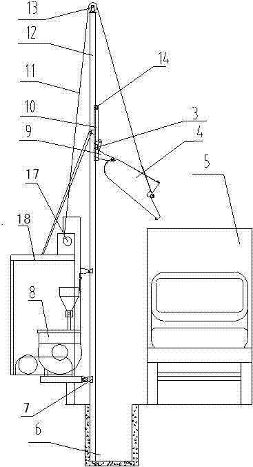
图1为本发明卸料时结构示意图。 Fig. 1 is the structure schematic diagram when unloading of the present invention.
图2为本发明装料时结构示意图。 Fig. 2 is a structural schematic diagram of the present invention when charging.
图3为本发明行程开关与控制系统连接结构示意图。 Fig. 3 is a schematic diagram of the connection structure between the travel switch and the control system of the present invention.
图4为本发明行程开关和伸缩限位支架安装位置结构示意图。 Fig. 4 is a schematic diagram of the installation position of the travel switch and the telescopic limit bracket of the present invention.
图5为本发明图3和图4A处得放大视图。 Fig. 5 is an enlarged view of Fig. 3 and Fig. 4A of the present invention.
图6为本发明提升料斗结构示意图。 Fig. 6 is a structural schematic diagram of the lifting hopper of the present invention.
图7为本发明提升料斗与活动支铰连接结构示意图。 Fig. 7 is a schematic diagram of the connection structure between the lifting hopper and the movable hinge of the present invention.
具体实施方式 Detailed ways
如图1、2、3、4、5、6、7所示,一种多工位快速卸料装料机构,包括设置有进料仓16的搅拌滚筒8,所述的搅拌滚筒8外部设置有第一支撑架18,第一支撑架18下方对应搅拌滚筒8出料口的位置设置有接料仓6,接料仓6内固定安装有升降杆12,升降杆12上安装有行程开关1和伸缩限位支架2,在升降杆12的顶部安装有定滑轮13,定滑轮13上设置有升降索11,升降索11的一端与固定安装在第一支撑架18上的电机17相连接,另一端与提升料斗4相连接,提升料斗4的底部与能够沿升降杆12上下滑动的滑动限位装置相连接。
As shown in Figures 1, 2, 3, 4, 5, 6, and 7, a multi-station fast unloading and loading mechanism includes a
所述的滑动限位装置包括料斗滑动架10以及固定安装在料斗滑动架10上的活动支铰9和定位支绞3,其中,活动支铰9上安装有能够沿活动支铰9旋转的提升料斗4,在料斗滑动架10上安装有滑轮14,料斗滑动架10通过滑轮14活动安装在升降杆12上。所述的行程开关1通过导线与控制系统22相连接。所述的升降杆12通过第二支撑架7和支撑杆15固定安装在第一支撑架18一侧。所述的行程开关1和伸缩限位支架2均至少为一个,并且行程开关1和伸缩限位支架2的数目相同。所述的提升料斗4上设置有旋转杆19,旋转杆19与升降索11相连接。所述的提升料斗4底部连接有提升料斗旋转架20,提升料斗旋转架20上开设有孔,该孔内安装有轴21,活动支铰9通过轴21与提升料斗旋转架20相连接。所述的控制系统22内设置有能够接收行程开关1发出的信号并对该信号进行处理实现控制电机17开停以及控制伸缩限位支架2伸缩的中央处理器23。所述的支撑杆15与升降杆12之间的夹角至少为30度。所述的提升料斗4与提升料斗旋转架20的连接方式为焊接。
The sliding limit device includes a
如图1、2、3、4、5、6、7所示,装料时,搅拌合格的沥青混合料通过搅拌滚筒8排出流进提升料斗4里,这时提升料斗4在接料仓6内接料,沥青混合料接满后,提升料斗4根据工程车5的高度确定提升料斗4的高度,升降杆12上安装若干个行程开关1和伸缩限位支架2,电机17带动升降索11可作升降运动,升降索11的另一头与提升料斗4相连接,通过定滑轮13将提升料斗4升起,提升料斗4再带动料斗滑动架10在升降杆12做升降运动,料斗滑动架10包括活动支铰9和定位支绞3,通过行程开关1和伸缩限位支架2确定、固定提升位置,根据工程车5的高度,在升降杆12上不同的高度位置均设置有行程开关1和伸缩限位支架2,只要工程车5的高度确定,料斗滑动架10升至相对于工程车5的合适位置后,行程开关接收到料斗滑动架10到指定位置的信号,并将该信号传输至控制系统22内,控制系统22内设置有能够接收行程开关1发出的信号并对该信号进行处理实现控制电机17开停以及控制伸缩限位支架2伸缩的中央处理器23,中央处理器23发出命令,电机17停机,是升降索11停止运动,提升料斗4停止运动,同时,伸缩限位支架2伸出,支撑住料斗滑动架10使其不再下滑,这样在升降索和伸缩限位支架2的共同作用下,料斗滑动架10停止运动并限位,此时,中央处理器23发出命令,电机17运转,料斗滑动架10上的提升料斗4在活动支铰9和提升料斗旋转架20的作用下,围绕轴21做轴向运动,在提升料斗4上的旋转杆19以及提升料斗4自身重力的作用下,提升料斗4内的物料开始向工程车5内卸料。卸料完毕后,中央处理器23发出命令,电机17转动,同时伸缩限位支架2收缩,料斗滑动架10解除限位,提升料斗4向下运动,直至落入接料仓6内,搅拌滚筒8开始工作,想提升料斗4内重新注入新的搅拌好的物料,重现重复卸料和喂料的动作。
As shown in Figures 1, 2, 3, 4, 5, 6, and 7, when charging, the qualified asphalt mixture is discharged through the
另外,本发明也可以通过人工实现控制料斗滑动架10的高度,可设置外接开关实现对伸缩限位支架2伸缩的控制,也可以实现本发明相同的效果。
In addition, the present invention can also control the height of the
本发明中升降杆12的高度可根据同批次或同批量施工现场的环境和工程车的平均高度来做不同的调整,并可按照要求设计生产。
The height of the
本发明保证了装车和卸料的工作质量,并大大提高了装料卸料和装车的工作效率,改善了施工者的工作环境,降低了劳动强度,节省了资源,减少的资源的浪费,并降低了生产成本。 The invention ensures the working quality of loading and unloading, greatly improves the working efficiency of loading, unloading and loading, improves the working environment of the builders, reduces labor intensity, saves resources, and reduces waste of resources , and reduce production costs.
Claims (6)
Priority Applications (1)
| Application Number | Priority Date | Filing Date | Title |
|---|---|---|---|
| CN 201110114093 CN102286911B (en) | 2011-05-04 | 2011-05-04 | Multi-station fast material unloading and loading mechanism |
Applications Claiming Priority (1)
| Application Number | Priority Date | Filing Date | Title |
|---|---|---|---|
| CN 201110114093 CN102286911B (en) | 2011-05-04 | 2011-05-04 | Multi-station fast material unloading and loading mechanism |
Publications (2)
| Publication Number | Publication Date |
|---|---|
| CN102286911A CN102286911A (en) | 2011-12-21 |
| CN102286911B true CN102286911B (en) | 2013-04-03 |
Family
ID=45333642
Family Applications (1)
| Application Number | Title | Priority Date | Filing Date |
|---|---|---|---|
| CN 201110114093 Expired - Fee Related CN102286911B (en) | 2011-05-04 | 2011-05-04 | Multi-station fast material unloading and loading mechanism |
Country Status (1)
| Country | Link |
|---|---|
| CN (1) | CN102286911B (en) |
Families Citing this family (2)
| Publication number | Priority date | Publication date | Assignee | Title |
|---|---|---|---|---|
| CN110342275B (en) * | 2019-08-06 | 2024-03-08 | 佛山市骏鹰环境能源装备有限公司 | Heterogeneous organic solid waste feeding device |
| CN112721953A (en) * | 2020-11-18 | 2021-04-30 | 高胜寒 | Automatic pedal device for eliminating gap between rail train door and subway platform |
Family Cites Families (5)
| Publication number | Priority date | Publication date | Assignee | Title |
|---|---|---|---|---|
| BE1003135A3 (en) * | 1990-01-16 | 1991-12-03 | P V B A W Everaert | MACHINE FOR CRUSHING CONCRETE SURFACES. |
| ES2546084T3 (en) * | 2007-09-27 | 2015-09-18 | E-Mak Makine Insaat Ticaret Ve Sanayi A.S. | A method and system to recycle hot asphalt |
| CN201326145Y (en) * | 2008-11-26 | 2009-10-14 | 三一重工股份有限公司 | Low asphalt concrete plant-mix heat regenerating device |
| CN201416139Y (en) * | 2009-06-23 | 2010-03-03 | 湘潭公路机械制造有限公司 | Gas generating device for heating asphalt aggregates |
| CN202099715U (en) * | 2011-05-04 | 2012-01-04 | 河南路太养路机械股份有限公司 | Quick loading unloading mechanism with multiple working positions |
-
2011
- 2011-05-04 CN CN 201110114093 patent/CN102286911B/en not_active Expired - Fee Related
Also Published As
| Publication number | Publication date |
|---|---|
| CN102286911A (en) | 2011-12-21 |
Similar Documents
| Publication | Publication Date | Title |
|---|---|---|
| CN209476184U (en) | A kind of multistation glue mixing machine | |
| CN207206773U (en) | a concrete production line | |
| CN110653945A (en) | Compact modularization concrete mixing equipment | |
| CN209552121U (en) | A raw material mixing device for autoclaved aerated concrete block production | |
| CN203569891U (en) | Novel concrete hopper for construction | |
| CN204447926U (en) | Mix device | |
| CN105773825B (en) | Multistation automatic distributing system | |
| CN106672468B (en) | A kind of stirring-type solid powder hopper jamming device | |
| CN103481374A (en) | Conveying system for aerial bunker of mixing station | |
| CN205312680U (en) | Take material loading machine of refining mechanism | |
| CN102286911A (en) | Multi-station fast material unloading and loading mechanism | |
| CN214515194U (en) | Coarse material returning device of slag micro powder pulverizing system | |
| CN208915927U (en) | A kind of uniform blanking hopper of architectural engineering | |
| CN202099715U (en) | Quick loading unloading mechanism with multiple working positions | |
| CN210194437U (en) | A high-efficiency bridge concrete pouring equipment | |
| CN210525493U (en) | Concrete mixing plant loading attachment | |
| CN221988611U (en) | A converter steelmaking charging device | |
| CN218345365U (en) | Fermented material turns over heap machine | |
| CN215050059U (en) | Intelligent integrated equipment of drying in air of stand | |
| CN214082145U (en) | Powder feeding device of concrete mixing plant | |
| CN205097366U (en) | A lifting support for cement mixer automatic feed | |
| CN213170270U (en) | Feeding and discharging conveyor of stirrer | |
| CN208645679U (en) | A kind of mixing device manufacturing permeable stone | |
| CN210082108U (en) | Over-and-under type mixer feeder | |
| CN220561879U (en) | A mixing station for rapid mixing of self-insulating block base materials |
Legal Events
| Date | Code | Title | Description |
|---|---|---|---|
| C06 | Publication | ||
| PB01 | Publication | ||
| C10 | Entry into substantive examination | ||
| SE01 | Entry into force of request for substantive examination | ||
| C14 | Grant of patent or utility model | ||
| GR01 | Patent grant | ||
| CF01 | Termination of patent right due to non-payment of annual fee | ||
| CF01 | Termination of patent right due to non-payment of annual fee |
Granted publication date: 20130403 |