CN102248455B - Hydrostatic pressure type numerical control horizontal shaft circular table surface grinding machine - Google Patents
Hydrostatic pressure type numerical control horizontal shaft circular table surface grinding machine Download PDFInfo
- Publication number
- CN102248455B CN102248455B CN 201110209976 CN201110209976A CN102248455B CN 102248455 B CN102248455 B CN 102248455B CN 201110209976 CN201110209976 CN 201110209976 CN 201110209976 A CN201110209976 A CN 201110209976A CN 102248455 B CN102248455 B CN 102248455B
- Authority
- CN
- China
- Prior art keywords
- main shaft
- sleeve
- grinding head
- numerical control
- grinding machine
- Prior art date
- Legal status (The legal status is an assumption and is not a legal conclusion. Google has not performed a legal analysis and makes no representation as to the accuracy of the status listed.)
- Expired - Fee Related
Links
Images

Landscapes
- Constituent Portions Of Griding Lathes, Driving, Sensing And Control (AREA)
Abstract
本发明涉及一种液体静压式数控卧轴圆台平面磨床。现有平面磨床的磨头机构的主轴回转精度较低,工作可靠性较差。本发明其特征在于所述的磨头机构包括主轴,主轴的外部套置一套筒,所述套筒的两端设置与主轴相配的角接触轴承,套筒外设置磨头体,所述的套筒与主轴之间留有间隙,所述的套筒上还设有一向间隙内补充油液的管接头。本发明的液体静压式磨头机构在工作时其内腔中始终充满足够的油液,使主轴具有较好的回转精度,在较大的变速和载荷范围内始终保持稳定可靠,主轴轴承系统的刚性强度好,工作稳定可靠,有效降低温升。
The invention relates to a liquid static pressure numerical control horizontal axis circular table surface grinder. The main shaft rotation precision of the grinding head mechanism of the existing surface grinder is low, and the work reliability is poor. The present invention is characterized in that the grinding head mechanism includes a main shaft, a sleeve is placed outside the main shaft, angular contact bearings matching the main shaft are arranged at both ends of the sleeve, and a grinding head body is arranged outside the sleeve. There is a gap between the sleeve and the main shaft, and the sleeve is also provided with a pipe joint for replenishing oil in the gap. When the hydrostatic grinding head mechanism of the present invention is working, its inner cavity is always filled with enough oil, so that the main shaft has better rotation accuracy, and it is always stable and reliable in a large range of speed change and load. The main shaft bearing system The rigidity is good, the work is stable and reliable, and the temperature rise is effectively reduced.
Description
技术领域 technical field
本发明涉及一种液体静压式数控卧轴圆台平面磨床。The invention relates to a liquid static pressure numerical control horizontal axis circular table surface grinder.
背景技术 Background technique
磨头机构是磨床的关键部件,磨头与垂直升降机构连接,并通过砂轮的高速旋转对工件进行切削。因此磨头的结构及质量直接影响到磨削的质量及生产率。随着经济的发展,磨削行业对磨床的生产效率、自动化程度和精度的要求越来越高,因而对磨头的要求也在不断的提高。除了要求质量轻、体积小、制造容易、调整简单、维修方便、工艺性好符合多快好省的原则之外,在技术上还要求:一、进一步提高主轴的回转精度,在较大的变速和载荷范围内保持稳定可靠;二、进一步提高主轴轴承系统的刚性;三、减少振动,降低温升。磨头的传动系统相对比较简单,主轴和轴承是其关键零件,特别是轴承,没有良好的轴承,主轴就不能正常运转,而现有的磨头机构均不能较好的满足上述要求。The grinding head mechanism is the key component of the grinding machine. The grinding head is connected with the vertical lifting mechanism and cuts the workpiece through the high-speed rotation of the grinding wheel. Therefore, the structure and quality of the grinding head directly affect the quality and productivity of grinding. With the development of the economy, the grinding industry has higher and higher requirements for the production efficiency, automation and precision of the grinding machine, so the requirements for the grinding head are also constantly improving. In addition to the requirements of light weight, small size, easy manufacture, simple adjustment, convenient maintenance, and good manufacturability, in line with the principle of more speed, better economy, the technical requirements are: 1. Further improve the rotation accuracy of the spindle, and in the larger speed change It remains stable and reliable within the load range; second, further improves the rigidity of the spindle bearing system; third, reduces vibration and temperature rise. The transmission system of the grinding head is relatively simple. The main shaft and the bearing are its key parts, especially the bearing. Without a good bearing, the main shaft cannot operate normally, and the existing grinding head mechanism can not meet the above requirements well.
发明内容 Contents of the invention
本发明针对现有技术存在的缺陷,提供一种液体静压式数控卧轴圆台平面磨床,能提高磨头机构的主轴回转精度,确保主轴工作可靠性,提高刚性,减少振动,降低温升。Aiming at the defects in the prior art, the present invention provides a hydrostatic numerical control horizontal-axis circular table surface grinder, which can improve the rotation accuracy of the main shaft of the grinding head mechanism, ensure the reliability of the main shaft, improve rigidity, reduce vibration and lower temperature rise.
为此,本发明采取如下技术方案:一种液体静压式数控卧轴圆台平面磨床,包括床身、立柱、工作台机构、垂直进给机构、磨头机构和横向进给机构,横向进给机构设置在床身上,工作台机构固定于横向进给结构上;垂直进给机构安装在立柱上端部,且与磨头机构固定连接,其特征在于所述的磨头机构包括主轴,主轴的外部套置一套筒,所述套筒的两端设置与主轴相配的角接触轴承,套筒外设置磨头体,所述的套筒与主轴之间留有间隙,所述的套筒上还设有一向间隙内补充油液的管接头。磨头机构启动工作时,磨头电机带动主轴旋转进行工作。油液由外部的油箱在压力的作用下通过管接头进入套筒的螺旋油槽中,并充满套筒与主轴的间隙中,使磨头机构的内腔充满足够的油液,保证磨头机构能稳定运行,多余的油液则通过电机座的另一管接头流出,通过过滤后可进行回用。主轴电机采用三相交流伺服电机,保证液体静压轴承平稳工作的同时,也大大提高了磨头的转速,使磨头的磨削效率达到高速的水平。For this reason, the present invention adopts the following technical scheme: a kind of hydrostatic numerical control horizontal axis circular table surface grinder, comprising bed, column, workbench mechanism, vertical feed mechanism, grinding head mechanism and lateral feed mechanism, lateral feed The mechanism is arranged on the bed, and the workbench mechanism is fixed on the transverse feed structure; the vertical feed mechanism is installed on the upper end of the column, and is fixedly connected with the grinding head mechanism, which is characterized in that the grinding head mechanism includes a main shaft, and A sleeve is set, and the two ends of the sleeve are provided with angular contact bearings matching the main shaft, and the grinding body is arranged outside the sleeve, and there is a gap between the sleeve and the main shaft, and the sleeve is also There is a pipe joint for replenishing oil into the gap. When the grinding head mechanism starts to work, the grinding head motor drives the main shaft to rotate to work. The oil enters the spiral oil groove of the sleeve from the external oil tank through the pipe joint under the action of pressure, and fills the gap between the sleeve and the main shaft, so that the inner cavity of the grinding head mechanism is filled with enough oil to ensure the performance of the grinding head mechanism. Stable operation, the excess oil flows out through another pipe joint of the motor base, and can be reused after being filtered. The spindle motor adopts three-phase AC servo motor, which not only ensures the stable operation of the hydrostatic bearing, but also greatly increases the speed of the grinding head, so that the grinding efficiency of the grinding head can reach a high-speed level.
所述工作台机构包括拖板、转轴、支承座、外挡油圈、大皮带轮、内挡油圈、工作台台面、角接触球轴承、轴承轴、电机、小皮带轮,支承座的一端通过转轴置于托板上,另一端通过一调节螺钉支撑,所述的支承座上设有供油液运行的导轨面,导轨面上还设有进油孔,并装有节流装置。工作台工作时,油箱内的油液经过一定的压力通过节流装置输送到支承座的导轨面,形成油膜,将与支承座相互接触的大皮带轮表面顶起,电机通过大小皮带轮带动工作台旋转,从而实现液体摩擦。其主要优点为:1、摩擦系数小,机械效率高;2、导轨面之间建立起一层很薄的油膜,油膜具有良好的润滑性和吸振性,因此静压导轨比其他结构的使用寿命长,甚至长期使用无磨损,且工作运动平稳;3、相对运动速度的变化对油膜厚度和刚度的影响小;4、消除了工作台低速运动的现象,降低对导轨材料的要求。The workbench mechanism includes a carriage, a rotating shaft, a support seat, an outer oil retaining ring, a large pulley, an inner oil retaining ring, a table top, an angular contact ball bearing, a bearing shaft, a motor, a small pulley, and one end of the support seat passes through the rotating shaft Placed on the supporting plate, the other end is supported by an adjusting screw. The support base is provided with a guide rail surface for oil liquid operation, and an oil inlet hole is also provided on the guide rail surface, and a throttling device is installed. When the workbench is working, the oil in the oil tank is transported to the guide rail surface of the support base through a throttling device under a certain pressure, forming an oil film, which lifts up the surface of the large pulley that is in contact with the support base, and the motor drives the workbench to rotate through the pulleys. , thus achieving liquid friction. Its main advantages are: 1. Small friction coefficient and high mechanical efficiency; 2. A thin oil film is established between the guide rail surfaces. The oil film has good lubricity and vibration absorption, so the service life of the static pressure guide rail is longer than that of other structures. Long, even long-term use without wear, and the working movement is stable; 3. The change of relative movement speed has little influence on the thickness and stiffness of the oil film; 4. The phenomenon of low-speed movement of the worktable is eliminated, and the requirements for the material of the guide rail are reduced.
所述的轴承轴安装在支承座上,轴承轴与大皮带轮内孔通过角接触球轴承相接,轴承轴内部装有导电装置,所述的工作台台面与大皮带轮连接,同时大皮带轮通过多楔带与小皮带轮连接,所述的小皮带轮与工作台电机相连。工作台的拖板安装在床身的直线导轨上,由磨床的横向进给机构带动工作台左右移动The bearing shaft is installed on the support seat, the bearing shaft is connected with the inner hole of the large pulley through an angular contact ball bearing, and a conductive device is installed inside the bearing shaft. The wedge belt is connected with the small pulley, and the small pulley is connected with the workbench motor. The carriage of the working table is installed on the linear guide rail of the bed, and the horizontal feeding mechanism of the grinding machine drives the working table to move left and right
所述套筒的前后端设有前压盖和后压盖。减小主轴的轴向窜动,提升主轴动作的稳定性。The front and rear ends of the sleeve are provided with a front gland and a rear gland. Reduce the axial movement of the spindle and improve the stability of the spindle movement.
所述的磨头体上设有连接丝母座,其特征在于所述的连接丝母座与磨床的垂直升降机构连接。The grinding head body is provided with a connecting thread female seat, which is characterized in that the connecting thread female seat is connected with the vertical lifting mechanism of the grinding machine.
所述立柱的侧面设有控制垂直进给机构、横向进给机构以及工作台机构运动的操作箱。An operation box for controlling the movement of the vertical feed mechanism, the lateral feed mechanism and the workbench mechanism is provided on the side of the column.
本发明的液体静压式磨头机构在工作时其内腔中始终充满足够的油液,使主轴具有较好的回转精度,在较大的变速和载荷范围内始终保持稳定可靠,主轴轴承系统的刚性强度好,工作稳定可靠,有效降低温升。When the hydrostatic grinding head mechanism of the present invention is working, its inner cavity is always filled with enough oil, so that the main shaft has better rotation accuracy, and it is always stable and reliable in a large range of speed change and load. The main shaft bearing system The rigidity is good, the work is stable and reliable, and the temperature rise is effectively reduced.
附图说明 Description of drawings
图1为本发明的磨床示意图;Fig. 1 is the grinding machine schematic diagram of the present invention;
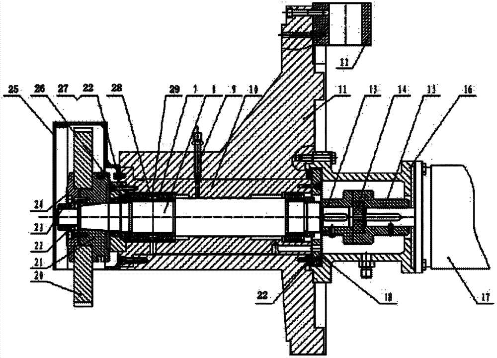
图2为本发明的磨头机构示意图;Fig. 2 is the schematic diagram of grinding head mechanism of the present invention;
图3为本发明的工作台机构的示意图;Fig. 3 is the schematic diagram of workbench mechanism of the present invention;
具体实施方式 Detailed ways
如图1所示的液体静压式数控卧轴圆台平面磨床,主要由床身1、立柱5、工作台机构2、垂直进给机构、磨头机构4和横向进给机构3构成,横向进给机构3设置在床身1上,工作台机构2固定于横向进给结构3上;垂直进给机构安装在立柱5上端部,且与磨头机构4固定连接。工作台机构的上端设置吸盘6,立,5的侧面还安装控制垂直进给机构、横向进给机构3以及工作台机构2运动的操作箱。As shown in Figure 1, the hydrostatic CNC horizontal-axis circular table surface grinder is mainly composed of a bed 1, a column 5, a table mechanism 2, a vertical feed mechanism, a grinding head mechanism 4, and a lateral feed mechanism 3. The feeding mechanism 3 is arranged on the bed 1, the workbench mechanism 2 is fixed on the transverse feeding structure 3; the vertical feeding mechanism is installed on the upper end of the column 5, and is fixedly connected with the grinding head mechanism 4. The upper end of workbench mechanism is provided with sucker 6, vertical, and the side of 5 is also installed the operation box of control vertical feed mechanism, transverse feed mechanism 3 and workbench mechanism 2 motions.
如图2所示,磨头机构包括主轴8、主轴电机17,砂轮20、砂轮定位盘21、砂轮压板24、砂轮罩壳25,以及用于固定砂轮的垫片22、螺母23等连接件。主轴8的外部套置一套筒10,套筒10的前端安装两组与主轴8相配的角接触轴承7,相邻两组角接触轴承7之间设有内隔圈28和外隔圈29,套筒10的后端同样设有一组角接触轴承7。套筒10外还安装磨头体11,套筒10与主轴8之间留有间隙,套筒10上还装有一向间隙内补充油液的管接头9。磨头体11上设有连接丝母座12,该连接丝母座12与垂直升降机构连接。套筒11的前后端分别装有前压盖27、后压盖18和以及用于连接固定的螺母26和调整垫片22。主轴8后端的电机座16内还设有左联轴器13和右联轴器15以及滑块14。As shown in Figure 2, the grinding head mechanism includes a main shaft 8, a main shaft motor 17, a grinding
如图3所示,工作台机构包括拖板30、转轴31、支承座32、外挡油圈33、大皮带轮34、内挡油圈35、工作台台面36、角接触球轴承37、轴承轴38、工作台电机40、小皮带轮39,支承座32的一端通过转轴31置于托板30上,另一端通过一调节螺钉支撑,支承座32上设有供油液运行的导轨面,导轨面上还设有进油孔,并装有节流装置(图中未示)。轴承轴38安装在支承座32上,轴承轴38与大皮带轮34内孔通过角接触球轴承37相接,轴承轴38内部装有导电装置,工作台台面36与大皮带轮34连接,同时大皮带轮34通过多楔带与小皮带轮39连接,小皮带轮39与工作台电机40相连。As shown in Figure 3, the workbench mechanism includes a carriage 30, a rotating shaft 31, a support seat 32, an outer oil retaining ring 33, a large pulley 34, an inner oil retaining ring 35, a workbench surface 36, an angular contact ball bearing 37, a bearing shaft 38. Workbench motor 40, small pulley 39, one end of the support seat 32 is placed on the supporting plate 30 through the rotating shaft 31, and the other end is supported by an adjusting screw. There is also an oil inlet hole and a throttling device (not shown in the figure). The bearing shaft 38 is installed on the support seat 32, the bearing shaft 38 is connected with the inner hole of the large pulley 34 through the angular contact ball bearing 37, the inside of the bearing shaft 38 is equipped with a conductive device, the worktable table 36 is connected with the large pulley 34, and the large pulley 34 is connected with small pulley 39 by V-ribbed belt, and small pulley 39 links to each other with workbench motor 40.
工作台工作时,油液通过油箱(外部配件)经过一定的压力通过节流装置输送到支承座的导轨面,形成油膜,将与支承座相互接触的大皮带轮表面顶起,电机通过大小皮带轮带动工作台旋转,从而实现液体摩擦。工作台吸盘通电充磁后产生磁场吸住工件,磨头下降到指定位置后启动,工作台左右移动,磨头根据程序编写的进给量对工件磨削加工,完成加工后砂轮退出并停止运转,工作台也在指定位置停止运动,吸盘退磁后即可取出加工好的工件。When the workbench is working, the oil is transported to the guide rail surface of the support seat through the oil tank (external accessories) through the throttling device under a certain pressure, forming an oil film, which lifts up the surface of the large pulley that is in contact with the support seat, and the motor is driven by the large and small pulleys. The table rotates, thus achieving liquid friction. After the workbench suction cup is energized and magnetized, a magnetic field is generated to attract the workpiece. The grinding head is lowered to the designated position and then started. The workbench moves left and right. The grinding head grinds the workpiece according to the feed amount written in the program. , the worktable also stops at the designated position, and the processed workpiece can be taken out after the suction cup is demagnetized.
磨头机构启动工作时,磨头电机带动主轴旋转进行工作。油液在压力的作用下通过管接头进入套筒的螺旋油槽中,并充满套筒与主轴的间隙中,液体静压磨头的内腔充满足够的油液,保证液体静压磨头能稳定运行,多余的油液则通过电机座的另一管接头流出,通过过滤后可进行回用。主轴电机采用三相交流伺服电机,保证液体静压轴承平稳工作的同时,也大大提高了磨头的转速,使磨头的磨削效率达到高速的水平。When the grinding head mechanism starts to work, the grinding head motor drives the main shaft to rotate to work. Under the action of pressure, the oil enters the spiral oil groove of the sleeve through the pipe joint, and fills the gap between the sleeve and the main shaft. The inner cavity of the hydrostatic grinding head is filled with enough oil to ensure the stability of the hydrostatic grinding head. Running, the excess oil flows out through another pipe joint of the motor base, and can be reused after being filtered. The spindle motor adopts three-phase AC servo motor, which not only ensures the stable operation of the hydrostatic bearing, but also greatly increases the speed of the grinding head, so that the grinding efficiency of the grinding head can reach a high-speed level.
需要特别指出的是,上述实施例的方式仅限于描述实施例,但本发明不止局限于上述方式,且本领域的技术人员据此可在不脱离本发明的范围内方便的进行修饰,因此本发明的范围应当包括本发明所揭示的原理和新特征的最大范围。It should be pointed out that the manner of the above-mentioned embodiment is only limited to the description of the embodiment, but the present invention is not limited to the above-mentioned manner, and those skilled in the art can conveniently make modifications without departing from the scope of the present invention. Therefore, the present invention The scope of the invention should include the broadest range of the principles and novel features disclosed in the invention.
Claims (5)
Priority Applications (1)
| Application Number | Priority Date | Filing Date | Title |
|---|---|---|---|
| CN 201110209976 CN102248455B (en) | 2011-07-26 | 2011-07-26 | Hydrostatic pressure type numerical control horizontal shaft circular table surface grinding machine |
Applications Claiming Priority (1)
| Application Number | Priority Date | Filing Date | Title |
|---|---|---|---|
| CN 201110209976 CN102248455B (en) | 2011-07-26 | 2011-07-26 | Hydrostatic pressure type numerical control horizontal shaft circular table surface grinding machine |
Publications (2)
| Publication Number | Publication Date |
|---|---|
| CN102248455A CN102248455A (en) | 2011-11-23 |
| CN102248455B true CN102248455B (en) | 2013-06-05 |
Family
ID=44976209
Family Applications (1)
| Application Number | Title | Priority Date | Filing Date |
|---|---|---|---|
| CN 201110209976 Expired - Fee Related CN102248455B (en) | 2011-07-26 | 2011-07-26 | Hydrostatic pressure type numerical control horizontal shaft circular table surface grinding machine |
Country Status (1)
| Country | Link |
|---|---|
| CN (1) | CN102248455B (en) |
Families Citing this family (2)
| Publication number | Priority date | Publication date | Assignee | Title |
|---|---|---|---|---|
| CN107932253B (en) * | 2017-12-25 | 2024-04-09 | 常州卓研精机科技有限公司 | Ultra-precise machining and polishing machine tool for large-caliber optical element |
| CN116833838B (en) * | 2023-07-28 | 2025-07-01 | 浙江固本精密技术有限公司 | Hydrostatic numerical control horizontal axis round table surface grinding machine |
Family Cites Families (2)
| Publication number | Priority date | Publication date | Assignee | Title |
|---|---|---|---|---|
| CN2062671U (en) * | 1989-12-17 | 1990-09-26 | 胡惜时 | High-speed internal grinding head of static and dynamic pressure bearing |
| CN201881224U (en) * | 2010-07-30 | 2011-06-29 | 浙江勤龙机械科技股份有限公司 | NC (numerical control) horizontal spindle round table surface grinding machine |
-
2011
- 2011-07-26 CN CN 201110209976 patent/CN102248455B/en not_active Expired - Fee Related
Also Published As
| Publication number | Publication date |
|---|---|
| CN102248455A (en) | 2011-11-23 |
Similar Documents
| Publication | Publication Date | Title |
|---|---|---|
| CN204036207U (en) | Thrust ball bearing ring face groove grinder | |
| CN105479313A (en) | Vertical double-face grinding machine | |
| CN102179735A (en) | Cylindrical grinding machine for bearing ring | |
| CN202070965U (en) | Cylindrical grinding machine of bearing collar | |
| CN110976925B (en) | A double vertical wall type full gas static pressure vertical lathe | |
| CN105935860A (en) | Curved surface machining method | |
| CN118106873A (en) | A high-rigidity five-axis linkage ultra-precision grinding machine tool | |
| CN106624951B (en) | A kind of Z-direction micro-displacement structure based on wedge shape feeding level compensating | |
| CN205734213U (en) | A kind of robot RV reducer planet wheel spindle bearing bore system Special precision grinding machine | |
| CN101367168B (en) | Double column vertical lathe | |
| CN205074931U (en) | Automatic grinder | |
| CN204935343U (en) | Roller sphere mill overcharge is put | |
| CN210475752U (en) | Finish machining vertical gear honing machine for high-quality hard tooth surface gear | |
| CN205588077U (en) | Large -scale bent axle follow -up grinding machine | |
| CN101157189A (en) | Circular saw blade profile centerless grinding machine and method for centerless grinding circular saw blade profile | |
| CN201211610Y (en) | Double column vertical lathe | |
| CN203282178U (en) | Large vertical type high-speed numerically controlled lathe | |
| CN212122650U (en) | Vertical and horizontal dual-purpose side upright column type circular truncated cone surface grinding machine | |
| CN211305968U (en) | Polishing machine tool intelligence spindle unit | |
| CN102248455A (en) | Hydrostatic pressure type numerical control horizontal shaft circular table surface grinding machine | |
| CN206083952U (en) | Mill at longmen with natural granite grinds hard rail and mixed main shaft of liquid static and dynamic pressure | |
| CN101683717B (en) | Grinding machine equipment for grinding internal surface of column | |
| CN109571193A (en) | A kind of outer alley grinding machine | |
| CN202640106U (en) | Polishing wheel mechanism for polishing machine | |
| CN204295445U (en) | The middle-size and small-size planar-formed grinding machine that a kind of column and grinding head body entirety move up and down |
Legal Events
| Date | Code | Title | Description |
|---|---|---|---|
| C06 | Publication | ||
| PB01 | Publication | ||
| C10 | Entry into substantive examination | ||
| SE01 | Entry into force of request for substantive examination | ||
| C14 | Grant of patent or utility model | ||
| GR01 | Patent grant | ||
| C41 | Transfer of patent application or patent right or utility model | ||
| TR01 | Transfer of patent right |
Effective date of registration: 20160115 Address after: 313307 Huzhou Province, Anji County town, Mei Mei Industrial Park, block 3 Patentee after: ZHEJIANG CHUANGLONG ROBOT MANUFACTURING Co.,Ltd. Address before: 313307, Zhejiang County, Huzhou City, Anji Province town villa industry function zone Patentee before: ZHEJIANG QINLONG MACHINERY TECHNOLOGY CO.,LTD. |
|
| DD01 | Delivery of document by public notice |
Addressee: Head of Zhejiang chuanglong Robot Manufacturing Co.,Ltd. Document name: Notification that Application Deemed not to be Proposed |
|
| TR01 | Transfer of patent right | ||
| TR01 | Transfer of patent right |
Effective date of registration: 20170421 Address after: 313307 Huzhou Province, Anji County town, Mei Mei Park Industrial Park, the building of the 1 (Zhejiang Qin Long Machinery Polytron Technologies Inc) Patentee after: ANJI YUANMO MACHINERY TECHNOLOGY CO.,LTD. Address before: 313307 Huzhou Province, Anji County town, Mei Mei Industrial Park, block 3 Patentee before: ZHEJIANG CHUANGLONG ROBOT MANUFACTURING Co.,Ltd. |
|
| CP03 | Change of name, title or address | ||
| CP03 | Change of name, title or address |
Address after: 313000 Building 1, Xiaoshu Industrial Park, Meixi Town, Anji County, Huzhou City, Zhejiang Province Patentee after: Anji circular grinding machinery technology Co.,Ltd. Address before: 313307 Building 1, Xiaoshu Industrial Park, Meixi Town, Anji County, Huzhou City, Zhejiang Province Patentee before: ANJI YUANMO MACHINERY TECHNOLOGY CO.,LTD. |
|
| CP03 | Change of name, title or address | ||
| CP03 | Change of name, title or address |
Address after: 313000 Building 1, Liangting Gangcheng New Lighting Factory, Xilong Township, Anji County, Huzhou City, Zhejiang Province Patentee after: Zhejiang Anji Circular Grinding Machine Technology Co.,Ltd. Address before: 313000 Building 1, Xiaoshu Industrial Park, Meixi Town, Anji County, Huzhou City, Zhejiang Province Patentee before: Anji circular grinding machinery technology Co.,Ltd. |
|
| CF01 | Termination of patent right due to non-payment of annual fee | ||
| CF01 | Termination of patent right due to non-payment of annual fee |
Granted publication date: 20130605 |