CN102239300A - Mount for installing structure, and solar cell system - Google Patents
Mount for installing structure, and solar cell system Download PDFInfo
- Publication number
- CN102239300A CN102239300A CN200980148054XA CN200980148054A CN102239300A CN 102239300 A CN102239300 A CN 102239300A CN 200980148054X A CN200980148054X A CN 200980148054XA CN 200980148054 A CN200980148054 A CN 200980148054A CN 102239300 A CN102239300 A CN 102239300A
- Authority
- CN
- China
- Prior art keywords
- bracket
- solar cell
- frame
- base
- mounting frame
- Prior art date
- Legal status (The legal status is an assumption and is not a legal conclusion. Google has not performed a legal analysis and makes no representation as to the accuracy of the status listed.)
- Pending
Links
Images




Classifications
-
- H—ELECTRICITY
- H02—GENERATION; CONVERSION OR DISTRIBUTION OF ELECTRIC POWER
- H02S—GENERATION OF ELECTRIC POWER BY CONVERSION OF INFRARED RADIATION, VISIBLE LIGHT OR ULTRAVIOLET LIGHT, e.g. USING PHOTOVOLTAIC [PV] MODULES
- H02S30/00—Structural details of PV modules other than those related to light conversion
- H02S30/10—Frame structures
-
- F—MECHANICAL ENGINEERING; LIGHTING; HEATING; WEAPONS; BLASTING
- F24—HEATING; RANGES; VENTILATING
- F24S—SOLAR HEAT COLLECTORS; SOLAR HEAT SYSTEMS
- F24S25/00—Arrangement of stationary mountings or supports for solar heat collector modules
- F24S25/10—Arrangement of stationary mountings or supports for solar heat collector modules extending in directions away from a supporting surface
- F24S25/13—Profile arrangements, e.g. trusses
-
- F—MECHANICAL ENGINEERING; LIGHTING; HEATING; WEAPONS; BLASTING
- F24—HEATING; RANGES; VENTILATING
- F24S—SOLAR HEAT COLLECTORS; SOLAR HEAT SYSTEMS
- F24S40/00—Safety or protection arrangements of solar heat collectors; Preventing malfunction of solar heat collectors
- F24S40/40—Preventing corrosion; Protecting against dirt or contamination
- F24S40/44—Draining rainwater or condensation
-
- H—ELECTRICITY
- H02—GENERATION; CONVERSION OR DISTRIBUTION OF ELECTRIC POWER
- H02S—GENERATION OF ELECTRIC POWER BY CONVERSION OF INFRARED RADIATION, VISIBLE LIGHT OR ULTRAVIOLET LIGHT, e.g. USING PHOTOVOLTAIC [PV] MODULES
- H02S20/00—Supporting structures for PV modules
- H02S20/10—Supporting structures directly fixed to the ground
-
- H—ELECTRICITY
- H02—GENERATION; CONVERSION OR DISTRIBUTION OF ELECTRIC POWER
- H02S—GENERATION OF ELECTRIC POWER BY CONVERSION OF INFRARED RADIATION, VISIBLE LIGHT OR ULTRAVIOLET LIGHT, e.g. USING PHOTOVOLTAIC [PV] MODULES
- H02S20/00—Supporting structures for PV modules
- H02S20/20—Supporting structures directly fixed to an immovable object
- H02S20/22—Supporting structures directly fixed to an immovable object specially adapted for buildings
- H02S20/23—Supporting structures directly fixed to an immovable object specially adapted for buildings specially adapted for roof structures
- H02S20/24—Supporting structures directly fixed to an immovable object specially adapted for buildings specially adapted for roof structures specially adapted for flat roofs
-
- Y—GENERAL TAGGING OF NEW TECHNOLOGICAL DEVELOPMENTS; GENERAL TAGGING OF CROSS-SECTIONAL TECHNOLOGIES SPANNING OVER SEVERAL SECTIONS OF THE IPC; TECHNICAL SUBJECTS COVERED BY FORMER USPC CROSS-REFERENCE ART COLLECTIONS [XRACs] AND DIGESTS
- Y02—TECHNOLOGIES OR APPLICATIONS FOR MITIGATION OR ADAPTATION AGAINST CLIMATE CHANGE
- Y02B—CLIMATE CHANGE MITIGATION TECHNOLOGIES RELATED TO BUILDINGS, e.g. HOUSING, HOUSE APPLIANCES OR RELATED END-USER APPLICATIONS
- Y02B10/00—Integration of renewable energy sources in buildings
- Y02B10/10—Photovoltaic [PV]
-
- Y—GENERAL TAGGING OF NEW TECHNOLOGICAL DEVELOPMENTS; GENERAL TAGGING OF CROSS-SECTIONAL TECHNOLOGIES SPANNING OVER SEVERAL SECTIONS OF THE IPC; TECHNICAL SUBJECTS COVERED BY FORMER USPC CROSS-REFERENCE ART COLLECTIONS [XRACs] AND DIGESTS
- Y02—TECHNOLOGIES OR APPLICATIONS FOR MITIGATION OR ADAPTATION AGAINST CLIMATE CHANGE
- Y02E—REDUCTION OF GREENHOUSE GAS [GHG] EMISSIONS, RELATED TO ENERGY GENERATION, TRANSMISSION OR DISTRIBUTION
- Y02E10/00—Energy generation through renewable energy sources
- Y02E10/40—Solar thermal energy, e.g. solar towers
- Y02E10/47—Mountings or tracking
-
- Y—GENERAL TAGGING OF NEW TECHNOLOGICAL DEVELOPMENTS; GENERAL TAGGING OF CROSS-SECTIONAL TECHNOLOGIES SPANNING OVER SEVERAL SECTIONS OF THE IPC; TECHNICAL SUBJECTS COVERED BY FORMER USPC CROSS-REFERENCE ART COLLECTIONS [XRACs] AND DIGESTS
- Y02—TECHNOLOGIES OR APPLICATIONS FOR MITIGATION OR ADAPTATION AGAINST CLIMATE CHANGE
- Y02E—REDUCTION OF GREENHOUSE GAS [GHG] EMISSIONS, RELATED TO ENERGY GENERATION, TRANSMISSION OR DISTRIBUTION
- Y02E10/00—Energy generation through renewable energy sources
- Y02E10/50—Photovoltaic [PV] energy
Landscapes
- Engineering & Computer Science (AREA)
- Architecture (AREA)
- Civil Engineering (AREA)
- Structural Engineering (AREA)
- Sustainable Development (AREA)
- Life Sciences & Earth Sciences (AREA)
- Physics & Mathematics (AREA)
- Sustainable Energy (AREA)
- Thermal Sciences (AREA)
- Chemical & Material Sciences (AREA)
- Combustion & Propulsion (AREA)
- Mechanical Engineering (AREA)
- General Engineering & Computer Science (AREA)
- Roof Covering Using Slabs Or Stiff Sheets (AREA)
- Photovoltaic Devices (AREA)
Abstract
以三角构造的支架为前提,即使不特别地增加零件件数,也能提高载置用框架的前端部和托架间的强度,容易定位太阳能电池模块,还能防止托架或托架周边的金属件的腐蚀。前方托架(73)的抵接部(73m)使太阳能电池模块(2)的框部件(21)定位于比前方托架(73)的底板(73a)向该抵接部(73m)侧突出的位置。因此,即便雨水浸入到太阳能电池模块(2)与载置用框架(11)之间,并且该雨水传递到太阳能电池模块(2)的底面,渐渐流动,从而使该雨水成为水滴(W)从太阳能电池模块(2)的端部滴落,该水滴(W)也不会下落到前方托架(73)的底板(73a)或基轨(71)上。
Based on the triangular structure of the support, even without increasing the number of parts, the strength between the front end of the mounting frame and the bracket can be improved, making it easier to position the solar cell module and preventing corrosion of the bracket or the metal parts around the bracket. The abutment part (73m) of the front bracket (73) positions the frame component (21) of the solar cell module (2) at a position that protrudes from the bottom plate (73a) of the front bracket (73) toward the abutment part (73m). Therefore, even if rainwater seeps between the solar cell module (2) and the mounting frame (11), and the rainwater is transferred to the bottom surface of the solar cell module (2) and gradually flows, so that the rainwater drips (W) from the end of the solar cell module (2), the water droplets (W) will not fall onto the bottom plate (73a) of the front bracket (73) or the base rail (71).
Description
技术领域 technical field
本发明涉及适于将太阳能电池模块等平板状的构造物设置到地面或平屋顶上的构造物设置支架及使用了该构造物设置支架的太阳能电池系统。The present invention relates to a structure installation frame suitable for installing a flat structure such as a solar cell module on the ground or a flat roof, and a solar cell system using the structure installation frame.
背景技术 Background technique
在这种以往的支架中,为了将太阳能电池模块朝向太阳进行支承,将载置用框架相对地面或平屋顶等基础面倾斜地固定,并在该倾斜的载置用框架上支承太阳能电池模块。例如,如图41所示,将两个基础块201、202分离地固定,将载置用框架203的前端部203a连接固定于前方基础块201上,将纵框204的上端部204a连接于自载置用框架203的上端起四分之一左右的位置,并且将纵框204的下端部204b连接于后方基础块202,在载置用框架203与后方基础块202之间夹持设置纵框204,由此将载置用框架203倾斜地进行固定。然后,并排设置多根这样的载置用框架203,从而在这样的载置用框架203上载置并支承太阳能电池模块205。In such a conventional rack, in order to support the solar cell module toward the sun, a mounting frame is fixed obliquely to a base surface such as the ground or a flat roof, and the solar cell module is supported on the inclined mounting frame. For example, as shown in FIG. 41, two
或者,将四个脚部树立设置于地面或平屋顶上,使前侧的两个脚部短于后侧的两个脚部,在这些脚部上倾斜地固定支承矩形形状的框体,在该框体上载置太阳能电池模块,从而使太阳能电池模块的受光面大致朝向太阳光的入射方向(参照专利文献1、2)。Alternatively, the four legs are erected on the ground or on a flat roof so that the two legs on the front side are shorter than the two legs on the rear side, and the rectangular frame is fixed and supported obliquely on these legs. The solar cell module is placed on the frame so that the light-receiving surface of the solar cell module is generally oriented toward the incident direction of sunlight (see
专利文献1:日本特开2000-101123号Patent Document 1: Japanese Patent Laid-Open No. 2000-101123
专利文献2:日本特开平11-177115号Patent Document 2: Japanese Patent Application Laid-Open No. 11-177115
然而,在支承太阳能电池模块等平板状构造物的情况下,由于构造物所受的风压较大,因此不仅要承受构造物自身的载荷,还必须能充分地承受来自风压的载荷。However, in the case of supporting a flat structure such as a solar cell module, since the structure receives a large wind pressure, it must be able to sufficiently withstand not only the load of the structure itself but also the load from the wind pressure.
例如,如专利文献1、2所示,在树立设置四个脚部并在这些脚部上支承太阳能电池模块的构造中,当作用由构造物的重量或风压产生的载荷时,由于对各个脚部作用了垂直方向以及水平方向的力,因此为了防止这些脚部倒塌必须牢固地支承上述各脚部,为了固定支承脚部而需要增加螺栓或加强金属件的个数。然而,因此造成零件件数或组装工时数的增大,现场中的组装作业变得困难,成本上升。For example, as shown in
对此,如图41所示地将载置用框架203、纵框204以及基础面组装成三角的三角构造,即使不特别地增加零件件数,也能够充分承受垂直方向以及水平方向的任一方向的力。In contrast, as shown in FIG. 41, the triangular structure in which the
为了充分地维持这样的三角构造的本来的强度,除必须保证载置用框架203以及纵框204的强度之外,还需要充分提高载置用框架203、纵框204以及各基础块201、202的连接部位的强度。尤其,由于对载置用框架203的前端部作用有较大的力,所以有必要提高该前端部的连接强度。In order to sufficiently maintain the original strength of such a triangular structure, in addition to ensuring the strength of the placing
例如,在将载置用框架203的前端部紧固于被固定在基础块201侧的托架(未图示)这样的连接构造中,有必要增大载置用框架203的前端部与托架之间的强度。然而,如果为了提高强度而增加螺栓或加强金属件的个数,则像专利文献1、2那样造成零件件数或组装工时数的增大,现场中的组装作业变得困难,成本上升。For example, in a connection structure in which the front end of the
此外,为了使太阳能电池模块205朝向太阳,有时要加大载置用框架203的倾斜角度。在这种情况下,如果只将太阳能电池模块205载置到载置用框架203,则太阳能电池模块205会在载置用框架203上滑落,因此太阳能电池模块205的定位比较困难。因此,优选在载置用框架203上设置太阳能电池模块205的阻挡器等,但即使设置这样的阻挡器,零件件数或组装工时数也增加,组装作业困难,或者成本上升。In addition, in order to orient the
进一步,当雨水浸入太阳能电池模块205与载置用框架203之间时,该雨水流过太阳能电池模块的底面或载置用框架203的顶板并渐渐流出至载置用框架203的前端,从而使载置用框架203的前端的托架或托架周边的金属件潮湿,该潮湿的状态持续长时间时,存在托架或托架周边的金属件被腐蚀这样的问题。Furthermore, when rainwater infiltrates between the
发明内容 Contents of the invention
因此,本发明是鉴于上述以往的问题而提出的,其目的在于提供一种构造物设置支架以及使用了该构造物设置支架的太阳能电池系统,以三角构造的支架为前提,即便不特别地增加零件件数,也能提高载置用框架的前端部和托架之间的强度,使太阳能电池模块的定位容易,还能防止托架或托架周边的金属件的腐蚀。Therefore, the present invention was made in view of the above-mentioned conventional problems, and an object of the present invention is to provide a structure installation rack and a solar cell system using the structure installation rack. The number of parts increases the strength between the front end of the mounting frame and the bracket, facilitates the positioning of the solar cell module, and prevents corrosion of the bracket or metal parts around the bracket.
为了解决上述课题,本发明的构造物设置支架,具备被固定于基础面的前方托架和载置构造物的载置用框架,使载置用框架相对于基础面倾斜,利用前方托架来固定倾斜后的载置用框架的前端部,上述前方托架具有抵接部,该抵接部与在上述倾斜后的载置用框架上所载置的上述构造物的倾斜下侧的端部抵接。In order to solve the above-mentioned problems, the structure installation bracket of the present invention is provided with a front bracket fixed to the base surface and a mounting frame for placing the structure, and the mounting frame is inclined relative to the base surface, and the front bracket The front end portion of the tilted loading frame is fixed, and the front bracket has an abutment portion that is in contact with an inclined lower end portion of the structure placed on the tilted loading frame. Abut.
此外,通过上述构造物的倾斜下侧的端部与前方托架的抵接部抵接,来阻止载置用框架及构造物的移动。In addition, the movement of the mounting frame and the structure is prevented by the abutment of the inclined lower end of the structure against the contact portion of the front bracket.
进一步,上述前方托架具有与上述基础面抵接的底部和自该底部树立设置的侧壁部,该侧壁部被紧固于上述倾斜后的载置用框架的前端部,该侧壁部的前端侧与载置用框架的前端部相比向上侧突出从而形成上述抵接部,该抵接部与被载置于载置用框架上的上述构造物的倾斜下侧的端部抵接。Further, the front bracket has a bottom that contacts the base surface, and a side wall that stands up from the bottom, and the side wall is fastened to the front end of the tilted mounting frame, and the side wall The front end side of the front end protrudes upward compared with the front end portion of the placement frame to form the above-mentioned abutment portion, which abuts against the end portion on the inclined lower side of the above-mentioned structure placed on the placement frame. .
此外,利用上述前方托架的抵接部使上述构造物的倾斜下侧的端部定位于比前方托架的底部还突出的位置。In addition, the inclined lower end of the structure is positioned at a position protruding from the bottom of the front bracket by the contact portion of the front bracket.
进一步,将截面形状为帽型的基轨作为基础使用,该基轨的帽型开口侧朝向上方,从而使该基轨的帽型两侧的突边状平板部成为上述基础面,使上述前方托架在上述基轨的帽型开口侧与该帽型两侧的突边状平板部重叠地进行固定。Further, a base rail with a hat-shaped cross-sectional shape is used as a foundation, and the hat-shaped opening side of the base rail faces upward, so that the flange-shaped flat plate parts on both sides of the hat-shaped side of the base rail become the above-mentioned foundation surface, and the above-mentioned front The bracket is fixed on the hat-shaped opening side of the base rail so as to overlap the flange-shaped flat plate portions on both sides of the hat.
此外,具备:后方托架,其从上述前方托架分离并被固定于基础面;以及纵框,其连结于上述载置用框架与上述后方托架之间。Furthermore, a rear bracket separated from the front bracket and fixed to the base surface, and a vertical frame connected between the placement frame and the rear bracket are provided.
另一方面,本发明的太阳能电池系统并排设置多台上述本发明的构造物设置支架,在这些构造物设置支架上载置太阳能电池模块。On the other hand, in the solar cell system of the present invention, a plurality of the above-mentioned structure installation racks of the present invention are arranged side by side, and solar cell modules are placed on these structure installation racks.
例如,将截面形状为帽型的两根基轨固定成相互平行且使上述各基轨的帽型开口侧朝向上方,从而使这些基轨的帽型两侧的突边状平板部成为上述基础面,使上述各构造物设置支架的前方托架与一方基轨的帽型两侧的突边状平板部重叠地固定,使上述各构造物设置支架的后方托架与另一方基轨的帽型两侧的突边状平板部重叠地固定,使该各构造物设置支架的倾斜的载置用框架的前端部紧固于各自的前方托架,并且在上述各构造物设置支架的倾斜的载置用框架与各后方托架间插入并固定各自的纵框。For example, two base rails with hat-shaped cross-sectional shapes are fixed parallel to each other and the hat-shaped opening side of each base rail is directed upwards, so that the flange-shaped flat plate parts on both sides of the hat-shaped sides of these base rails become the above-mentioned foundation surface. , the front brackets of the above-mentioned structures are provided with the brackets and the protruding flat plate parts on both sides of the hat shape of one base rail are overlapped and fixed, and the rear brackets of the above-mentioned structures are provided with the brackets and the hat shape of the other base rail. The protruding flat plate parts on both sides are overlapped and fixed, and the front end of the inclined loading frame of each structure setting bracket is fastened to the respective front brackets, and the inclined loading frame of each structure setting bracket is fixed. Insert and fix the respective longitudinal frames between the placement frame and each rear bracket.
发明效果Invention effect
在本发明的构造物设置支架中,倾斜的载置用框架的前端部被固定于前方托架。另外,载置于倾斜后的载置用框架上的构造物的倾斜下侧的端部与前方托架的抵接部抵接。从而,不仅用载置用框架的前端部和前方托架的固定部来承受作用到载置用框架的载荷,还用构造物的倾斜下侧的端部所抵接的前方托架的抵接部来承受作用到载置用框架的载荷,从而分散到上述固定部以及上述抵接部的多个部位来进行承受。因此,与只用载置用框架的前端部与前方托架的固定部的一个部位来承受作用到载置用框架的所有载荷的情况相比,提高了载置用框架与前方托架间的连接部位的耐载荷性。并且,零件件数或组装工时数也不会增大。In the structure installation bracket of the present invention, the front end portion of the inclined mounting frame is fixed to the front bracket. In addition, the inclined lower end portion of the structure placed on the inclined mounting frame comes into contact with the contact portion of the front bracket. Therefore, not only the front end portion of the mounting frame and the fixing portion of the front bracket receive the load acting on the mounting frame, but also the abutment of the front bracket against which the end portion of the inclined lower side of the structure abuts. The load acting on the mounting frame is received by the fixed portion, and is distributed to a plurality of locations of the fixed portion and the abutting portion to receive the load. Therefore, compared with the case where only one part of the front end portion of the loading frame and the fixing portion of the front bracket bears all the loads acting on the loading frame, the distance between the loading frame and the front bracket is improved. Load resistance of the joint. Also, the number of parts and the number of assembly man-hours do not increase.
此外,前方托架的抵接部由于还具有作为阻止载置用框架及构造物的移动这样的阻挡器的功能,因此无需设置另外的阻挡器,由此也阻止了零件件数或组装工时数的增大。In addition, since the abutting portion of the front bracket also functions as a stopper that prevents the movement of the mounting frame and the structure, there is no need to provide a separate stopper, thereby preventing the number of parts and the number of assembly man-hours from increasing. increase.
例如,前方托架具有与基础面抵接的底部和从该底部树立设置的侧壁部,该侧壁部被紧固于倾斜后的载置用框架的前端部,该侧壁部的前端侧与载置用框架的前端部相比还向上侧突出,从而形成抵接部,该抵接部与载置到载置用框架上的构造物的倾斜下侧的端部抵接。由此,能够将抵接部与前方托架设为一体,能够防止零件件数或组装工时数的增大。For example, the front bracket has a bottom that is in contact with the base surface, and a side wall that is erected from the bottom. The side wall is fastened to the front end of the inclined mounting frame, and the front end of the side wall is The front end portion of the mounting frame protrudes upward to form an abutting portion that abuts against an obliquely lower end portion of a structure placed on the mounting frame. Accordingly, the abutting portion and the front bracket can be integrated, and an increase in the number of parts and the number of assembly man-hours can be prevented.
此外,利用前方托架的抵接部使构造物的倾斜下侧的端部定位于比前方托架的底部突出的位置。在这种情况下,即便雨水渗透到构造物的底面而从该构造物的倾斜下侧的端部滴落,该雨水也不会下落到前方托架的底部,前方托架的底部很难被腐蚀。In addition, the inclined lower end of the structure is positioned at a position protruding from the bottom of the front bracket by the contact portion of the front bracket. In this case, even if rainwater seeps into the bottom surface of the structure and drips from the end of the inclined lower side of the structure, the rainwater will not fall to the bottom of the front bracket, and the bottom of the front bracket is difficult to be cleaned. corrosion.
进一步,将截面形状为帽型的基轨作为基础使用,使该基轨的帽型开口侧朝向上方,从而使该基轨的帽型两侧的突边状平板部成为基础面,使前方托架在基轨的帽型开口侧与该帽型两侧的突边状平板部重叠地进行固定。截面形状为帽型的基轨,相对弯曲而言强度本来就高,很难变形,因此适合作为基础使用。进一步,当使前方托架在基轨的帽型开口侧与该帽型两侧的突边状平板部重叠地进行固定时,由于前方托架而帽型开口部位被关闭,因此相对于基轨的弯曲而言强度较高,得到更优选的基础构造。Further, the cross-sectional shape of the hat-shaped base rail is used as a basis, and the hat-shaped opening side of the base rail is directed upwards, so that the flange-shaped flat plate parts on both sides of the hat-shaped side of the base rail become the base surface, and the front supports The frame is fixed so that the hat-shaped opening side of the base rail overlaps the flange-shaped flat plate portions on both sides of the hat. The hat-shaped cross-sectional shape of the base rail is inherently high in strength against bending, and it is difficult to deform, so it is suitable for use as a foundation. Furthermore, when the front bracket is fixed on the hat-shaped opening side of the base rail so as to overlap the flange-shaped flat plate portions on both sides of the hat, the hat-shaped opening is closed due to the front bracket, so that the Higher strength in terms of bending, resulting in a more preferred base construction.
此外,由于具备与前方托架分离地固定于基础面的后方托架和连接载置用框架与后方托架间的纵框,因此能够构筑由载置用框架、纵框以及基础面构成的三角构造的支架。在这样的三角构造的支架中,即使载荷从任意方向作用于载置用框架,也能分散承受该载荷。因此,在载置用框架的上载置并固定太阳能电池模块等平板状的构造物的状态下,即使作用构造物自身的载荷或基于风压的载荷,也能够承受这些载荷。In addition, since the rear bracket fixed to the base surface separately from the front bracket and the vertical frame connecting the frame for placement and the rear bracket are provided, a triangle composed of the frame for placement, the vertical frame, and the base surface can be constructed. Constructed brackets. In such a triangular-structured stand, even if a load acts on the mounting frame from any direction, the load can be distributed and received. Therefore, in a state where a flat structure such as a solar cell module is placed and fixed on the mounting frame, even if a load of the structure itself or a load due to wind pressure acts on it, it can withstand these loads.
另一方面,本发明的太阳能电池系统并排设置多台上述本发明的构造物设置支架,并且在这些构造物设置支架上载置太阳能电池模块而成,因此能够起到与上述本发明的构造物设置支架相同的作用效果。On the other hand, since the solar cell system of the present invention is formed by arranging a plurality of the above-mentioned structure installation racks of the present invention side by side, and mounting solar cell modules on these structure installation racks, it can achieve the same effect as the above-mentioned structure installation racks of the present invention. The bracket has the same effect.
例如,将截面形状为帽型的两根基轨固定成相互平行且使该各基轨的帽型开口侧朝向上方,从而将这些基轨的帽型两侧的突边状平板部设为基础面,使各构造物设置支架的前方托架与一方基轨的帽型两侧的突边状平板部重叠地进行固定,使各构造物设置支架的后方托架与另一方基轨的帽型两侧的突边状平板部重叠地进行固定,将各构造物设置支架的倾斜后的载置用框架的前端部紧固于各自的前方托架,并且在该各构造物设置支架的倾斜后的载置用框架与各后方托架间插入并固定各自的纵框。在这种情况下,如前所述,由前方托架关闭帽型开口部位,因此相对于基轨的弯曲而言强度较高,获得了更优选的基础构造。此外,构筑由载置用框架、纵框以及基础面构成的三角构造的支架,提高了支架的耐载荷性。For example, two base rails with hat-shaped cross-sectional shapes are fixed parallel to each other and the hat-shaped opening side of each base rail faces upward, so that the flange-shaped flat plate parts on both sides of the hat-shaped sides of these base rails are used as the base surface. The front bracket of each structure setting bracket is overlapped with the flange-shaped flat plate parts on both sides of the hat shape of one base rail, and the rear bracket of each structure setting bracket is overlapped with the hat shape of the other base rail. The flange-shaped flat plate parts on the side are fixed overlappingly, and the front end of the inclined loading frame of each structure setting bracket is fastened to the respective front brackets, and the inclined mounting frame of each structure setting bracket is fixed. Each vertical frame is inserted and fixed between the mounting frame and each rear bracket. In this case, as described above, the hat-shaped opening is closed by the front bracket, so that the strength against the bending of the base rail is high, and a more preferable foundation structure is obtained. In addition, the stand with a triangular structure consisting of a mounting frame, a vertical frame, and a base surface is constructed, and the load resistance of the stand is improved.
附图说明 Description of drawings
图1为表示使用了本发明的构造物设置支架的一实施方式的太阳能电池系统的立体图。FIG. 1 is a perspective view showing a solar cell system using an embodiment of the structure installation rack of the present invention.
图2为表示本实施方式的构造物设置支架的侧视图。Fig. 2 is a side view showing the structure installation bracket of the present embodiment.
图3为表示前方托架相对于图2的构造物设置支架中的载置用框架的前端部的连接构造的侧视图。FIG. 3 is a side view showing a connection structure of the front bracket to the front end portion of the mounting frame in the structure installation bracket of FIG. 2 .
图4A为表示前方托架的立体图。Fig. 4A is a perspective view showing the front bracket.
图4B为表示前方托架的侧视图。Fig. 4B is a side view showing the front bracket.
图4C为表示前方托架的主视图。Fig. 4C is a front view showing the front bracket.
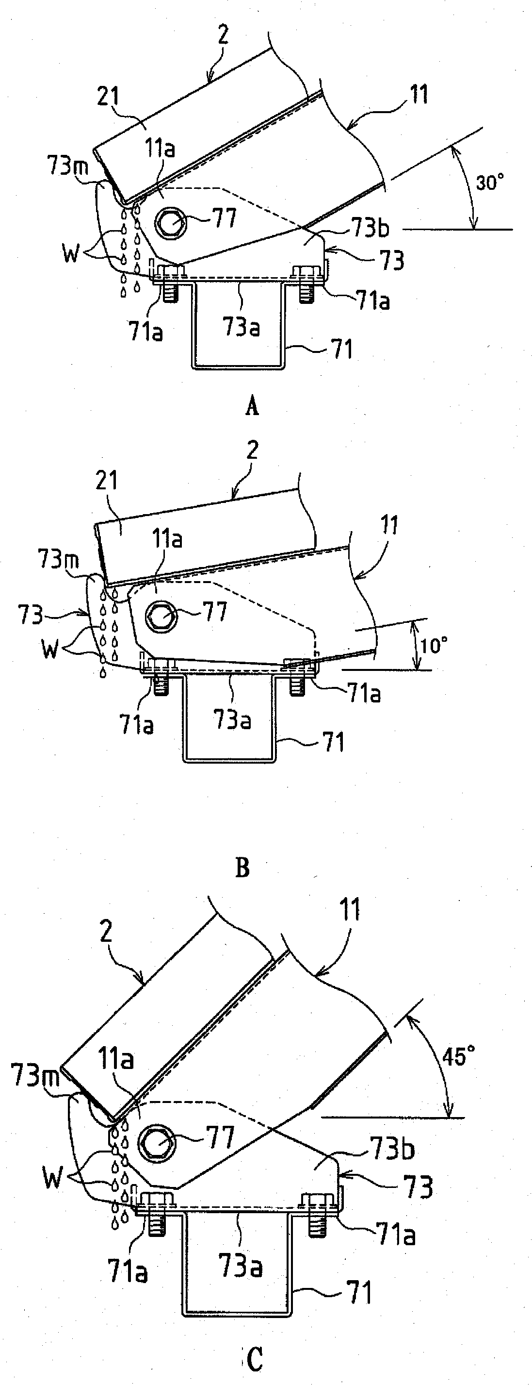
图5A为表示将太阳能电池模块以及载置用框架的倾斜角度设定为30°时的前方托架周边的侧视图。5A is a side view showing the periphery of the front bracket when the inclination angle of the solar cell module and the mounting frame is set to 30°.
图5B为将太阳能电池模块以及载置用框架的倾斜角度设定为10°时的前方托架周边的侧视图。5B is a side view of the periphery of the front bracket when the inclination angle of the solar cell module and the mounting frame is set to 10°.
图5C为将太阳能电池模块以及载置用框架的倾斜角度设定为45°时的前方托架周边的侧视图。5C is a side view of the periphery of the front bracket when the inclination angle of the solar cell module and the mounting frame is set to 45°.
图6A为将太阳能电池模块以及载置用框架的倾斜角度设定为30°时的前方托架周边的立体图。6A is a perspective view of the periphery of the front bracket when the inclination angle of the solar cell module and the mounting frame is set to 30°.
图6B为将太阳能电池模块以及载置用框架的倾斜角度设定为10°时的前方托架周边的立体图。6B is a perspective view of the periphery of the front bracket when the inclination angle of the solar cell module and the mounting frame is set to 10°.
图6C为将太阳能电池模块以及载置用框架的倾斜角度设定为45°时的前方托架周边的立体图。6C is a perspective view of the periphery of the front bracket when the inclination angle of the solar cell module and the mounting frame is set to 45°.
图7为表示后方托架相对于图2的构造物设置支架中的纵框的下端部的连接构造的立体图。7 is a perspective view showing a connection structure of the rear bracket to the lower end portion of the vertical frame in the structure installation bracket of FIG. 2 .
图8为表示图7的连接构造的侧视图。Fig. 8 is a side view showing the connection structure of Fig. 7 .
图9为表示图1的太阳能电池系统中的前方托架以及后方托架的设置工序的图。Fig. 9 is a view showing a step of installing a front bracket and a rear bracket in the solar cell system of Fig. 1 .
图10为表示图1的太阳能电池系统中的纵框的安装工序的图。Fig. 10 is a view showing a mounting process of a vertical frame in the solar cell system of Fig. 1 .
图11为表示支柱向图10的纵框的安装工序的图。Fig. 11 is a view showing a step of attaching a support column to the vertical frame in Fig. 10 .
图12为表示图1的太阳能电池系统中的载置用框架的安装工序的图。Fig. 12 is a diagram illustrating a mounting process of a mounting frame in the solar cell system of Fig. 1 .
图13为表示图1的太阳能电池系统中的载置用框架与纵框的定位情形的图。Fig. 13 is a view showing how the placement frame and the vertical frame are positioned in the solar cell system of Fig. 1 .
图14为表示并排设置多个构造物设置支架的状态的立体图。Fig. 14 is a perspective view showing a state in which a plurality of structure installation brackets are arranged side by side.
图15为表示在两个基轨上并排设置3台构造物设置支架的立体图。Fig. 15 is a perspective view showing three structure installation brackets arranged side by side on two base rails.
图16为表示在两个基轨上并排设置3台构造物设置支架的主视图。Fig. 16 is a front view showing three structure installation stands arranged side by side on two base rails.
图17为对图1的太阳能电池模块的框部件放大表示的剖视图。Fig. 17 is an enlarged cross-sectional view of a frame member of the solar cell module shown in Fig. 1 .
图18A为表示在图1的太阳能电池系统中的中央构造物设置支架的载置用框架上载置左右2台太阳能电池模块的端部并进行安装的状态的、从上方向看到的立体图。18A is a perspective view seen from above showing a state in which the ends of two left and right solar cell modules are placed and mounted on the mounting frame of the central structure installation bracket in the solar cell system of FIG. 1 .
图18B为表示图18A的状态的从下方看到的立体图。Fig. 18B is a perspective view showing the state of Fig. 18A seen from below.
图19为表示图18A的状态的剖视图。Fig. 19 is a sectional view showing the state of Fig. 18A.
图20为表示图2的构造物设置支架中的载置用框架的立体图。FIG. 20 is a perspective view showing a mounting frame in the structure installation rack of FIG. 2 .
图21为表示图2的构造物设置支架中的上部固定金属件的立体图。Fig. 21 is a perspective view showing an upper fixing metal fitting in the structure installation bracket of Fig. 2 .
图22为表示图2的构造物设置支架中的下部固定金属件的立体图。Fig. 22 is a perspective view showing a lower fixing metal fitting in the structure installation bracket of Fig. 2 .
图23为表示图2的构造物设置支架中的下部固定金属件的折曲状态的俯视图。Fig. 23 is a plan view showing a bent state of the lower fixing metal fitting in the structure installation bracket of Fig. 2 .
图24为表示图2的构造物设置支架中的下部固定金属件的折曲状态的、从表面侧看到的立体图。Fig. 24 is a perspective view from the surface side showing the bent state of the lower fixing metal fitting in the structure installation bracket of Fig. 2 .
图25为图2的构造物设置支架中的下部固定金属件的折曲状态的、从背面侧看到的立体图。Fig. 25 is a perspective view from the rear side of the bent state of the lower fixing metal fitting in the structure installation bracket of Fig. 2 .
图26为表示将图2的构造物设置支架中的下部固定金属件以及上部固定金属件安装到载置用框架的状态的立体图。26 is a perspective view showing a state in which the lower fixing bracket and the upper fixing bracket in the structure installation bracket of FIG. 2 are attached to the mounting frame.
图27为表示用于将图2的构造物设置支架中的下部固定金属件安装到载置用框架的顺序的立体图。Fig. 27 is a perspective view showing a procedure for attaching the lower fixing metal fittings in the structure installation bracket of Fig. 2 to the mounting frame.
图28为表示图27的后续顺序的立体图。FIG. 28 is a perspective view showing a sequence subsequent to FIG. 27 .
图29为表示图28的后续顺序的立体图。FIG. 29 is a perspective view showing a sequence subsequent to FIG. 28 .
图30为表示图29的后续顺序的立体图。FIG. 30 is a perspective view showing a procedure subsequent to FIG. 29 .
图31为表示太阳能电池模块的端部相对于图1的太阳能电池系统中的左侧以及右侧支架单元的安装构造的剖视图。Fig. 31 is a cross-sectional view showing an attachment structure of an end portion of a solar cell module to left and right frame units in the solar cell system of Fig. 1 .
图32为表示在图31的安装构造中使用的上部固定金属件的立体图。Fig. 32 is a perspective view showing an upper fixing metal used in the mounting structure of Fig. 31 .
图33A为对使用了本实施方式的构造物设置支架的太阳能电池系统的其他例子进行简要表示的俯视图。Fig. 33A is a plan view schematically showing another example of a solar cell system using the structure installation frame of this embodiment.
图33B为图33A的太阳能电池系统的主视图。Fig. 33B is a front view of the solar cell system of Fig. 33A.
图33C为图33A的太阳能电池系统的侧视图。Figure 33C is a side view of the solar cell system of Figure 33A.
图34A为表示图33A的太阳能电池系统中的桩子的俯视图。Fig. 34A is a plan view showing a stake in the solar cell system of Fig. 33A.
图34B为表示图33A的太阳能电池系统中的桩子的侧视图。Fig. 34B is a side view showing a stake in the solar cell system of Fig. 33A.
图35A为表示为了形成图33A的太阳能电池系统中的较长的基轨而排列连接的较短的基轨的俯视图。FIG. 35A is a plan view showing shorter base rails aligned and connected to form longer base rails in the solar cell system of FIG. 33A .
图35B为图35A的较短的基轨的侧视图。Figure 35B is a side view of the shorter base rail of Figure 35A.
图35C为表示图35A的较短的基轨的剖视图。Figure 35C is a cross-sectional view showing the shorter base rail of Figure 35A.
图36A为表示用于连接图35A的较短的基轨的基轨连结部件的俯视图。Fig. 36A is a plan view showing a base rail connecting member for connecting the shorter base rail of Fig. 35A.
图36B为图36A的基轨连结部件的剖视图。Fig. 36B is a cross-sectional view of the base rail connecting member of Fig. 36A.
图37A为表示图35A的较短的基轨的连接状态的俯视图。Fig. 37A is a plan view showing the connection state of the shorter base rail of Fig. 35A.
图37B为表示图35A的较短的基轨的连接状态的侧视图。Fig. 37B is a side view showing the connection state of the shorter base rail of Fig. 35A.
图38为对图37A中的较短的基轨的连接部位周边进行放大表示的俯视图。Fig. 38 is an enlarged plan view showing the periphery of the connecting portion of the shorter base rail in Fig. 37A.
图39为对图37A中的较短的基轨的连接部位周边进行放大表示的侧视图。Fig. 39 is an enlarged side view showing the vicinity of the connecting portion of the shorter base rail in Fig. 37A.
图40A为用于构筑图33的太阳能电池系统的施工顺序的说明图。FIG. 40A is an explanatory diagram of a construction procedure for constructing the solar cell system of FIG. 33 .
图40B为图40A的后续施工顺序的说明图。Fig. 40B is an explanatory diagram of the subsequent construction sequence of Fig. 40A.
图40C为图40B的后续施工顺序的说明图。Fig. 40C is an explanatory diagram of the subsequent construction sequence of Fig. 40B.
图40D为图40C的后续施工顺序的说明图。Fig. 40D is an explanatory diagram of the subsequent construction sequence of Fig. 40C.
图40E为图40D的后续施工顺序的说明图。Fig. 40E is an explanatory diagram of the subsequent construction sequence of Fig. 40D.
图40F为图40E的后续施工顺序的说明图。Fig. 40F is an explanatory diagram of the subsequent construction sequence of Fig. 40E.
图41为表示以往的支架的简要结构的立体图。Fig. 41 is a perspective view showing a schematic structure of a conventional stent.
具体实施方式 Detailed ways
以下,边参照附图边对本发明的实施方式进行详细说明。Hereinafter, embodiments of the present invention will be described in detail with reference to the drawings.
图1为表示使用了本发明的构造物设置支架的一实施方式的太阳能电池系统的立体图。此外,图2为表示本实施方式的构造物设置支架的侧视图。FIG. 1 is a perspective view showing a solar cell system using an embodiment of the structure installation rack of the present invention. Moreover, FIG. 2 is a side view which shows the structure installation bracket of this embodiment.
如图1所示,在太阳能电池系统1中,将两根基轨71、72固定于平屋顶等,在各基轨71、72上并排设置3台构造物设置支架10,并在各构造物设置支架10上载置并固定4枚太阳能电池模块2。As shown in Fig. 1, in the
各基轨71、72具有帽型的截面形状,帽型开口侧朝向上方,各基轨71、72隔开一定间隔并相互平行地固定于平屋顶等,各基轨71、72的帽型两侧的突边状平板部71a、72a定位于同一个二维平面上,由各基轨71、72的突边状平板部71a、72a形成平坦的基础面。构造物设置支架10载置并固定于各基轨71、72的突边状平板部71a、72a上、也就是平坦的基础面上。Each
太阳能电池模块2具备太阳能电池面板20和保持该太阳能电池面板20的框部件21。The
构造物设置支架10具有载置用框架11以及纵框16,自倾斜的载置用框架11的上端起四分之一左右的部位,固定了向与载置用框架11相反的朝向倾斜的纵框16的前端。The
3台构造物设置支架10以与太阳能电池模块2的宽度大致相同的间隔并排设置,在左侧构造物设置支架10的载置用框架11与中央构造物设置支架10的载置用框架11之间并列设置上下2枚太阳能电池模块2,在右侧构造物设置支架10的载置用框架11与中央构造物设置支架10的载置用框架11之间并列设置上下2枚太阳能电池模块2,共有4枚太阳能电池模块2的端部被载置安装于各构造物设置支架10的载置用框架11上。Three structure installation racks 10 are arranged side by side at approximately the same interval as the width of the
从而,在左侧以及右侧的构造物设置支架10的载置用框架11的顶板12上,分别配置有上下2枚太阳能电池模块2的端部,并且在中央构造物设置支架10的载置用框架11的顶板12上,左右分别配置有上下2枚的太阳能电池模块2的端部。Therefore, on the
接着,对构造物设置支架10的结构进行详细说明。在构造物设置支架10中,将前方托架73以及后方托架74固定于各自的基轨71、72的突边状平板部71a、72a,将载置用框架11的前端部11a连接固定于前方托架73,将纵框16的下端部连接于后方托架74,从而将纵框16夹持设置并固定于后方托架74与自载置用框架11的上端起四分之一左右的位置间。Next, the structure of the
载置用框架11只有其前端部11a具有大致U字型截面形状,从前端部11a附近到后端的范围则具有帽型的截面形状。此外,纵框16只有其上端部具有大致U字型截面形状,从上端部附近到下端的范围则具有帽型的截面形状。另外,在本说明书中,大致U字型包含具有角的U字型。The mounting
前方托架73、后方托架74、载置用框架11、纵框16均是对镀敷钢板等金属板进行切断以及折曲加工而成。The
图3为前方托架73相对表示载置用框架11的前端部11a的连接构造的侧视图。此外,图4A、图4B以及图4C为表示前方托架73的立体图、侧视图以及主视图。FIG. 3 is a side view showing the connection structure of the
前方托架73具有底板73a、在底板73a的两侧折曲后树立设置的各侧板73b、在底板73a的前后折曲后立起来的各加强部73d、73e。在前方托架73的底板73a形成有两个孔73f,在各侧板73b形成有各自的螺纹孔73g。The
此外,各侧板73b的上侧边缘呈曲线,在该上侧边缘形成顶部73i、肩部73j以及凹部73k,最为前端侧还形成有向上方突出且弯曲的抵接部73m。各侧板73b的抵接部73m与太阳能电池模块2的框部件21的倾斜下侧的端部抵接,从而承受太阳能电池模块2的载荷。因此,各侧板73b的抵接部73m的宽度形成为较宽以具有足够的强度,并且具有平滑的曲线的外边缘以不产生局部性强度不足。In addition, the upper edge of each
这样的前方托架73以横跨基轨71的各突边状平板部71a的方式载置于各突边状平板部71a上,两根螺栓75通过各自的垫圈76,进一步通过前方托架73的底板73a的各自的孔73f而被拧入基轨71的各突边状平板部71a的螺纹孔,从而将前方托架73固定于基础面。Such a
该基轨71由于其截面形状为帽型,所以相对于弯曲而言强度较高,很难变形。加之,由于将前方托架73在基轨71的帽型的开口侧与该帽型的两侧的突边状平板部71a重叠地进行固定,从而利用前方托架73关闭帽型的开口部位,因此相对于基轨71的弯曲而言强度较高,基础面的强度变得极高,获得更优选的基础构造。Since the
载置用框架11的前端部11a具有大致U字型截面形状,前端部11a的各侧板11b的内宽被设定为与前方托架73的各侧板73b的外宽相同、或者比该外宽稍宽,在前端部11a的各侧板11b的内侧夹入前方托架73的各侧板73b,从而使前端部11a的各侧板11b与前方托架73的各侧板73b重叠。The
另外,两根螺栓77通过各自的垫圈78,进一步通过前端部11a的各侧板11b的孔(未图示)而被拧入前方托架73的各侧板73b的螺纹孔73g而被紧固。由此,将载置用框架11的前端部11a连接固定于前方托架73。In addition, the two
在此,载置用框架11为了能够朝向太阳地支承太阳能电池模块2,相对于基础面倾斜地被支承。因此,如果将太阳能电池模块2只是载置到载置用框架11,则太阳能电池模块2将在载置用框架11上滑落,太阳能电池模块2的定位变得困难。Here, the mounting
然而,由于前方托架73的各侧板73b的抵接部73m抵接于太阳能电池模块2的框部件21,所以太阳能电池模块2不会在载置用框架11上滑落,太阳能电池模块2被各侧板73b的抵接部73m阻挡而被定位。However, since the abutting
此外,太阳能电池模块2的载荷,不仅用对载置用框架11的前端部11a与前方托架73进行紧固的螺栓77来承受,还用太阳能电池模块2的框部件21所抵接的前方托架73的抵接部73m来承受,从而分散到螺栓77以及抵接部73m这两个部位来承受。因此,与只用螺栓77这一个部位来承受太阳能电池模块2的所有载荷的情况相比,提高了载置用框架11与前方托架73间的连接部位的耐载荷性。In addition, the load of the
太阳能电池模块2,由于被设置于室外,并且受来自多个方向的风压,所以在载置用框架11的前端部11a作用多个方向的力。由于前方托架73的抵接部73m,尤其承受太阳能电池模块2的倾斜下侧方向(水流动方向)的力,因此提高了载置用框架11与前方托架73间的水流动方向的耐载荷性。Since the
进一步,如图5A以及图6A所示,前方托架73的抵接部73m将太阳能电池模块2的端部定位于比前方托架73的底板73a还靠该抵接部73m侧的位置。因此,即便雨水浸入到太阳能电池模块2与载置用框架11之间,并且该雨水渗透到太阳能电池模块2的底面,并渐渐流动,从而该雨水成为水滴W从太阳能电池模块2的端部滴落,该水滴W也不会下落到前方托架73的底板73a或基轨71。在图5A以及图6A中,太阳能电池模块2以及载置用框架11的倾斜角度为30°,但从图5B、图5C、图6B以及图6C可知,只要倾斜角度处于10°~45°的范围,前方托架73的抵接部73m就能与底板73a以及基轨71分离地被定位,从太阳能电池模块2的端部滴落的水滴W不会下落到前方托架73的底板73a或基轨71。因此,很难腐蚀前方托架73的底板73a或基轨71。Furthermore, as shown in FIGS. 5A and 6A , the
从而,前方托架73的抵接部73m同时具有作为定位太阳能电池模块2的阻挡器的功能、提高载置用框架11与前方托架73之间的连接部位的耐载荷性的功能以及防止水滴下落到前方托架73的底板73a或基轨71这三种功能。另外,由于抵接部73m与前方托架73设为一体,所以零件件数、组装工时数不会增加。Therefore, the
图7以及图8为表示后方托架74相对于纵框16的下端部16a的连接构造的立体图以及侧视图。此外,图9为表示后方托架74等的立体图。7 and 8 are perspective views and side views showing the connection structure of the
后方托架74具有底板74a、在底板74a的两侧折曲并树立设置的各侧板74b、在底板74a的前后折曲并树立设置的各加强部74d、74e。在后方托架74的底板74a,形成有两个孔74f。此外,在各侧板74b,形成有各自的螺纹孔74g。进一步,前侧的加强部74d在其途中倾斜地折曲,其倾斜的前端侧形成承受部74i。The
为了将该后方托架74固定于基础面,将后方托架74以横跨基轨72的各突边状平板部72a方式载置于各突边状平板部72a上,将两根螺栓81通过各自的垫圈82,进一步通过后方托架74的底板74a的孔74f而拧入基轨72的各突边状平板部72a的螺纹孔。In order to fix the
由于后方托架74与前方托架73一样地关闭基轨72的帽型的开口部位,因此相对基轨72弯曲而言强度较高,基础构造的强度变高。Since the
纵框16只有其上端部具有大致U字型截面形状,从上端部附近到下端的范围则具有帽型的截面形状,如图7以及图8所示,纵框16的各侧板16b的内宽被设定成与后方托架74的各侧板74b的外宽相同、或者比该外宽稍宽。在纵框16的下端部16a中,在各侧板16b的内侧夹入后方托架74的各侧板74b,从而使各侧板16b与后方托架74的各侧板74b重叠。此外,各侧板16b的下边与后方托架74的加强部74d的承受部74i抵接。Only the upper end of the
在该状态下,两根螺栓83通过各自的垫圈84,进一步通过纵框16的各侧板16b的孔(未图示)而被拧入后方托架74的各侧板74b的螺纹孔74g而被紧固。由此,将纵框16的下端部16a连接固定于后方托架74。In this state, the two
此时,在纵框16的下端部16a中,由于各侧板16b的下边与后方托架74的加强部74d的承受部74i抵接而被支承,因此纵框16以相对基础面倾斜的状态被支承。At this time, in the
如图2所示,纵框16的上端部16d插入于帽型载置用框架11的自上端起四分之一左右的部位的内侧,两根螺栓85通过载置用框架11的各侧壁的孔后被拧入纵框16的各侧壁的螺纹孔而被紧固,由此将纵框16的上端部16d连接固定于载置用框架11。As shown in FIG. 2 , the
在此,当从载置用框架11向纵框16作用载荷时,不仅用对纵框16的下端部16a与后方托架74进行紧固的两根螺栓83来承受基于该载荷的力,还用纵框16的各侧壁16b的下边所抵接的后方托架74的承受部74i来承受基于该载荷的力,从而分散到两根螺栓83以及后方托架74的承受部74i这样的多个部位来承受。因此,与只用螺栓来承受向后方托架74作用的力的情况相比,提高了纵框16与后方托架74间的连接部位的耐载荷性。并且,增加零件件数或组装工时数也不会增加。Here, when a load is applied from the mounting
此外,由于后方托架74的承受部74i从下方承受纵框16的各侧板16b的下边,因此阻止了绕各螺栓83而向纵框16的下方的旋转移动。因此,只通过将纵框16的下端部16a连接固定于后方托架74,能够以倾斜状态支承纵框16,构筑由载置用框架11、纵框16以及基础面构成的三角构造的构造物设置支架10时,其组装作业变的容易。Moreover, since the receiving part 74i of the
在这样的结构的构造物设置支架10中,从其整体观察时,载置用框架11、纵框16以及基础面被安装成三角形状。由于构成该三角形状的支架10,能够将作用到载置用框架11的力分散到该载置用框架11、纵框16以及基础面来承受,因此该支架10的强度变高。例如,能够将载置到载置用框架11上的太阳能电池模块2的载荷和施加到太阳能电池模块2的风压等,分散到载置用框架11、纵框16以及基础面来承受。In the structure installation stand 10 having such a structure, the mounting
此外,通过将载置用框架11、纵框16以及形成基础面的基轨71的截面形状设为帽型,使这些部件自身也提高各自的强度。Moreover, by making the cross-sectional shape of the
并且,在本实施方式中,如前所述由于载置用框架11与前方托架73间的连接部位的耐载荷性高,纵框16与后方托架74间的连接部位的耐载荷性也高,因此即便作用到构造物设置支架10的载荷集中于它们的连接部位,也能够承受该载荷。In addition, in this embodiment, since the load resistance of the joint between the
接着,对本实施方式的构造物设置支架10的组装方法进行说明。Next, a method of assembling the
首先,如图9所示,将截面形状为帽型的两根基轨71、72隔开一定间隔并相互平行地固定于平屋顶等,在由两根基轨71、72的各突边状平板部71a、72a形成平坦的基础面的各基轨71、72间倾斜地架设两根支柱91、92,将各支柱91、92的两端用螺栓以及螺母固定于各基轨71、72。First, as shown in FIG. 9, two
然后,在前方的基轨71的各突边状平板部71a上以横跨各突边状平板部71a的方式配置前方托架73,并且在后方的基轨72的突边状平板部72a以横跨突边状平板部72a的方式配置后方托架74,在与各基轨71、72正交的直线上排列一组前方托架73以及后方托架74,利用两根螺栓75固定前方托架73,利用两根螺栓81固定后方托架74(详细部分参照图3、图8)。Then, the
此外,将三组前方托架73以及后方托架74沿着各基轨71、72以一定间隔配设。In addition, three sets of
然后,如图10所示(详细部分参照图7、图8),按每个后方托架74,在纵框16的下端部16a将后方托架74的各侧板74b夹入各侧板16b的内侧,将两根螺栓83通过纵框16的各侧板16b的孔而拧入后方托架74的各侧板74b的螺纹孔74g来进行紧固,从而将纵框16的下端部16a连接固定于后方托架74。此时,由于纵框16的各侧板16b的下边抵接于后方托架74的承受部74i而被支承,因此纵框16以相对基础面倾斜的状态被支承。Then, as shown in FIG. 10 (see FIG. 7 and FIG. 8 for details), each
如图11所示,在相邻的两根纵框16之间倾斜地架设两根支柱93,用螺栓以及螺母将各支柱93的两端固定于各纵框16。As shown in FIG. 11 , two
接着,如图12所示(详细部分参照图2、图3),将前方托架73的各侧板73b夹入载置用框架11的前端部11a的各侧板11b的内侧,将两根螺栓77通过前端部11a的各侧板11b的孔而拧入前方托架73的各侧板73b的螺纹孔73g来进行紧固,从而将载置用框架11的前端部11a连接固定于前方托架73。Next, as shown in FIG. 12 (refer to FIG. 2 and FIG. 3 for details), each
此外,如图13所示,将纵框16的上端部16d插入自载置用框架11的上端起四分之一左右的部位的内侧,将两根螺栓85通过载置用框架11的各侧壁的孔而拧入纵框16的各侧壁的螺纹孔来进行紧固,从而将纵框16的上端部16d连结固定于载置用框架11。此时,由于纵框16维持倾斜状态,所以能够便于进行载置用框架11与纵框16的上端部16d的定位。In addition, as shown in FIG. 13 , the
如图14所示,按每个前方托架73,将载置用框架11的前端部11a连接固定于前方托架73。由此,按每个前方托架73以及后方托架74,均将载置用框架11以及纵框16组装成三角形状,从而完成如图15以及图16所示在各基轨71上并排设置的3台构造物设置支架10。As shown in FIG. 14 , the
在这样的构造物设置支架10的组装方法中,将纵框16连接固定到后方托架74时,由于以倾斜状态支承纵框16,因此将纵框16的上端部16d插入自载置用框架11的上端起四分之一左右的部位的内侧并连结固定的作业工序变得容易,能够由一人之力完成该作业工序。此外,对于其他的作业工序,也不特别困难,能够由一人之力完成。In such an assembly method of the
并且,按每个构造物设置支架10均具有三角形状的构造,并且相邻的构造物设置支架10间倾斜地架设有多个支柱,因此全体的强度非常高。Furthermore, each
接着,简要说明太阳能电池模块2的端部相对于构造物设置支架10的载置用框架11的安装构造。Next, the mounting structure of the mounting
如图1以及图2所示,在左侧以及右侧的构造物设置支架10的载置用框架11的顶板12上,载置有上下2枚太阳能电池模块2的端部,并且在中央构造物设置支架10的载置用框架11的顶板12上,左右分别载置并安装有上下2枚太阳能电池模块2的端部。从而,左侧以及右侧构造物设置支架10与中央构造物设置支架10,太阳能电池模块2的端部的安装构造不同,存在两种安装构造。因此,分别说明各个安装构造。As shown in Figures 1 and 2, on the
首先,说明太阳能电池模块2的端部相对于中央构造物设置支架10的安装构造。First, a description will be given of an attachment structure in which the end portion of the
如图17所示,太阳能电池模块2的框部件21包括保持部22、从保持部22向下方延伸设置的壁部23、与太阳能电池面板20平行且与壁部23的下端连结的底部片24。As shown in FIG. 17 , the
另外,保持部22具有树立设置的保持壁22a、从保持壁22a的上端以及下端向相同的横方向延伸设置的保持上片22b以及保持下片22c,截面呈大致U字型。在该大致U字形的内侧,夹持太阳能电池面板20的端部。In addition, the holding
图18A为表示在中央构造物设置支架10的载置用框架11上载置左右太阳能电池模块2的端部并进行安装的状态的、从上方向看到的立体图,图18B为表示该状态的从下方看到的立体图。此外,图19为该状态的剖视图。18A is a perspective view from above showing a state in which the ends of the left and right
如图18A、图18B以及图19所示,左右太阳能电池模块2是使用上部固定金属件3a、下部固定金属件4以及作为紧固部件的螺栓8被安装于中央构造物设置支架10的载置用框架11的顶板12上,其中,上部固定金属件3a在太阳能电池模块2的受光面侧与框部件21抵接,下部固定金属件4在与太阳能电池模块的受光面相反的一侧与框部件21抵接。As shown in FIG. 18A, FIG. 18B and FIG. 19, the left and right
图20为表示构造物设置支架10的载置用框架11的立体图。如图20所示,在载置用框架11的顶板12上,形成有供螺栓8插入的顶板孔13、用于安装下部固定金属件4的T字形的安装辅助孔15以及定位狭缝14。FIG. 20 is a perspective view showing the mounting
顶板孔13为用于插入螺栓8的孔,为了微调该螺栓8的插入位置而形成为在左右方向细长的长孔。并且,定位狭缝14是用于插入后述的下部固定金属件4的定位片43的狭缝,为了微调该下部固定金属件4的定位片43的插入位置而形成为在左右方向细长的长孔。The
图21为表示上部固定金属件3a的立体图。如图21所示,上部固定金属件3a形成有在平板状的按压板31的前后两端部向下方突出的突起片32,并在按压板31的中央部以贯通方式形成有按压板孔33。Fig. 21 is a perspective view showing the upper fixing metal fitting 3a. As shown in FIG. 21 , the upper fixing
按压板31为了将相邻配置于构造物设置支架10的载置用框架11的顶板12上的2枚太阳能电池模块2的框部件21从上方进行按压而使用。并且,按压板孔33为供螺栓8插入的孔。上部固定金属件3a的突起片32被插入于左右太阳能电池模块2的间隙。The
图22为表示下部固定金属件4的立体图。如图22所示,下部固定金属件4具有上板40、下板50以及结合上板40与下板50的接头部60。为了便于折曲,在接头部60的途中形成有缩窄部61。FIG. 22 is a perspective view showing the lower
在下板50上形成有从其后端边缘垂直弯曲的下板后壁50b,还形成有从其前端边缘垂直弯曲的下板前壁50a。进一步,形成有从下板前壁50a的端缘垂直弯曲的卡合片50c。On the
在上板40的左右两端边缘形成有向上方弯曲的爪片41、41。此外,在上板40的后端边缘,形成有向下方弯曲的定位片43。进一步,在定位片43上形成有卡合槽43a。
此外,在上板40的中央部以贯通方式形成有上板孔42,在下板50上形成有下板紧固孔51。上板40的上板孔42为供螺栓8插入的孔,下板50的下板紧固孔51为供作为紧固部件的螺栓8拧入的螺纹孔。In addition, an
如图23至图25所示,下部固定金属件4的接头部60在缩窄部61被折曲,从而上板40与下板50相互隔开间隙被相向配置,上板40的定位片43嵌入下板50的卡合片50c的长孔50d,卡合片50c的凸部50e嵌入定位片43的长孔43a,从而上板40与下板50相互卡定。As shown in Figures 23 to 25, the
此外,如图26所示,在接头部60的缩窄部61折曲的状态下,下部固定金属件4卡定到载置用框架11的顶板12的T字形的安装辅助孔15以及定位狭缝14。In addition, as shown in FIG. 26 , in the state where the narrowed
然后,在图26的状态下,螺栓8插入到上部固定金属件3a的按压板孔33以及下部固定金属件4的上板40的上板孔42中,螺栓8通过顶板12的顶板孔13而被拧入下部固定金属件4的下板50的下板紧固孔51。左右太阳能电池模块2的框部件21搭载到位于螺栓8两侧的下板50的左右空间,这些太阳能电池模块2的框部件21被加入下板50与上部固定金属件3a间。Then, under the state of FIG. 26, the
图27至图30表示将下部固定金属件4安装到构造物设置支架10的载置用框架11的顶板12的顺序。27 to 30 show the procedure for attaching the lower
首先,如图27所示,在使下部固定金属件4的下板50的各爪片41与安装台11的顶板12的长度方向正交的状态下,如图28所示向安装辅助孔15插入至下部固定金属件4的接头部60。First, as shown in FIG. 27 , in the state where each
然后,如图29所示,将下部固定金属件4全体绕着接头部60旋转为直角,将下部固定金属件4的定位片43插入载置用框架11的顶板12的定位狭缝14,从而进行下部固定金属件4在前后方向的定位。Then, as shown in FIG. 29 , the entire lower fixing
进一步,如图30所示,将下部固定金属件4的接头部60的缩窄部61折曲90度,使下板50与上板40隔着顶板12相向配置,在下板50与上板40间夹持载置用框架11的顶板12,从而将下部固定金属件4安装于顶板12。此时,在下板50的卡合片50c的长孔50d嵌入上板40的定位片43,并在定位片43的长孔43a嵌入卡合片50c的凸部50e,从而使上板40与下板50相互卡定。Further, as shown in FIG. 30 , the narrowed
这样在将下部固定金属件4安装到顶板12的状态下,如图18A、图18B以及图19所示,在从下部固定金属件4的中央附近到左侧爪片41的空间中插入并配置左侧太阳能电池模块2的框部件21的底部片24,此外,在从下部固定金属件4的中央附近到右侧爪片41的空间中插入并配置右侧太阳能电池模块2的框部件21的底部片24,在各太阳能电池模块2的框部件21的保持部22上搭载上部固定金属件3a,将上部固定金属件3a的突起片32插入到左右太阳能电池模块2的间隙,将螺栓8插入上部固定金属件3a的按压板孔33以及上板40的上板孔42,将螺栓8通过顶板12的顶板孔13拧入下板50的下板紧固孔51,并紧固螺栓8。由此,左右太阳能电池模块2的框部件21被夹入下部固定金属件4与上部固定金属件3a之间而被固定支承。In this way, in the state where the lower
接着,说明太阳能电池模块2的端部相对于左侧以及右侧的构造物设置支架10的安装构造。其中,安装于左侧以及右侧构造物设置支架10的太阳能电池模块2的端部,与安装于中央构造物设置支架10的端部一样,如图17所示地构成。Next, the mounting structure of the end portion of the
图31为表示太阳能电池模块2端部的相对于左侧以及右侧构造物设置支架10的安装构造的剖视图。此外,图32为表示在图31的安装构造中使用的上部固定金属件3b的立体图。FIG. 31 is a cross-sectional view showing the installation structure of the end portion of the
如图32所示,上部固定金属件3b在平板状的按压板31的前后两端部形成有向下方突出的突起片32,在按压板31的中央部以贯通方式形成有按压板孔33,形成有从按压板31的一端缘垂直弯曲的立壁34,形成有从立壁34的下端缘横向弯曲的底部片35。As shown in FIG. 32 , the upper fixing
在左侧以及右侧构造物设置支架10的顶板12上,与中央构造物设置支架10的顶板12一样地,形成有供螺栓8插入的顶板孔13、用于安装下部固定金属件4的T字形的安装辅助孔15以及定位狭缝14,下部固定金属件4卡定于T字形的安装辅助孔15以及定位狭缝14。On the
如图31所示,在从下部固定金属件4的中央附近到内侧爪片41的空间插入并配置有左侧或右侧太阳能电池模块2的框部件21的底部片24,此外,在从下部固定金属件4的中央附近到外侧爪片41的空间配置有上部固定金属件3b的底部片35,在太阳能电池模块2的框部件21的保持部22上搭载上部固定金属件3b的按压板31,使上部固定金属件3b的突起片32推靠太阳能电池模块2的保持部22,从而定位太阳能电池模块2,将螺栓8插入上部固定金属件3b的按压板孔33以及下部固定金属件4的上板40的上板孔42,将螺栓8通过顶板12的顶板孔13拧入下板50的下板紧固孔51,并紧固螺栓8。由此,太阳能电池模块2的端部被夹入下部固定金属件4与上部固定金属件3b间而被固定支承。As shown in FIG. 31 , the
这样,在中央构造物设置支架10与左侧以及右侧构造物设置支架10中,太阳能电池模块2的端部的安装构造不同。然而,在将下侧左右2枚太阳能电池模块2搭载于3台构造物设置支架10的载置用框架11上时,使下侧左右2枚太阳能电池模块2的倾斜下侧的端部与各载置用框架11的前方托架73的抵接部73m抵接之后,按每个载置用框架11,在下部固定金属件与上部固定金属件之间夹入太阳能电池模块2的端部并进行固定。由此,如前所述,前方托架73的抵接部73m可同时具有作为定位太阳能电池模块2的阻挡器的功能、提高载置用框架11与前方托架73之间的连接部位的耐载荷性的功能以及防止水滴下落到前方托架73的底板73a或基轨71的功能这样的三种功能。In this way, the attachment structures of the ends of the
接着,对使用上述实施方式的构造物设置支架的太阳能电池系统的其他例子进行说明。图33A、图33B以及图33C为简要表示太阳能电池系统的全体结构的俯视图、主视图以及侧视图。Next, another example of a solar cell system in which a frame is installed using the structure of the above-mentioned embodiment will be described. 33A, 33B, and 33C are plan views, front views, and side views schematically showing the overall structure of the solar cell system.
在该太阳能电池系统中,如图33A~图33C所示,在地面GL沿着x方向相互平行地等间隔排成两排地打设多个桩子101,在上述两排的各桩子101上分别固定较长的基轨111、112,在这些基轨111、112上并排设置多个构造物设置支架10,并在这些构造物设置支架10上搭载多个太阳能电池模块(未图示)。In this solar cell system, as shown in FIGS. 33A to 33C , a plurality of
各桩子101被定位于其顶部高出地面GL30cm左右的上方位置,在这些桩子101的顶部分别搭载有基轨111、112。从而,各构造物设置支架10以及各太阳能电池模块,远离地面GL30cm以上。这是为了防止太阳能电池模块进入地面GL的杂草或邻近的围栏等的影子中,或者防止太阳能电池模块因大雨等而被浸水。Each of the
各基轨111、112具有帽型截面形状,帽型开口侧朝向上方,由各基轨111、112的突边状平板部形成平坦的基础面,各构造物设置支架10搭载并固定于各基轨111、112的突边状平板部上。各基轨111、112的长度达数十米。由于以单个构造实现这么长的基轨111、112较为困难,所以如后文所述那样排列连接多根较短的基轨来形成较长的基轨。Each
各构造物设置支架10为与图1、图2所示的支架一样,将前方托架73以及后方托架74固定于各自的基轨111、112的突边状平板部,将载置用框架11的前端部11a连接固定于前方托架73,将纵框16的下端部连接于后方托架74,从而将纵框16夹持设置在后方托架74与自载置用框架11的上端起四分之一左右的部位间而进行固定。然后,在相邻的2台构造物设置支架10的载置用框架11之间,排列配置上下2枚太阳能电池模块。在图33A以及图33B中,最左端及最右端的构造物设置支架10与图1中的左侧及右侧构造物设置支架10一样,上下2枚太阳能电池模块2的端部载置于它们的载置用框架11上。此外,在图33A以及图33B中,除最左端及最右端的其他各构造物设置支架10,与图1中的中央构造物设置支架10一样,上下2枚太阳能电池模块2的端部分别载置于其载置用框架11的左右侧。Each
图34A以及图34B为表示桩子101的俯视图以及侧视图。该桩子101具有下端尖锐的轴部101a、设置于轴部101a的上端的凸缘部101b,并且在凸缘部101b的外缘附近形成有共计6个孔101c、101d。此外,在桩子101的轴部101a的外周刻有外螺纹状的螺旋沟,只通过向地面打入桩子101的轴部101a,使轴部101a的外周螺旋沟咬住地面的土壤或石子儿,从而牢固地固定桩子101。由此,能够简化施工工程。34A and 34B are a plan view and a side view showing the
其中,替代桩子101,还可使用轴部的外周光滑的桩子,此时,在地面挖坑,并在该坑中立起桩子后流入混凝土来固定桩子。However, instead of the
图35A、图35B以及图35C为表示为了形成较长的各基轨111、112而排列连接的较短的各基轨71、72的俯视图、侧视图以及剖视图。这些基轨71、72相当于图1以及图2所示的各基轨71、72,其截面形状为帽型,并且在该帽型两侧形成有突边状平板部71a、72a。此外,在各基轨71、72的底板71b、72b的两端部,沿着基轨的长度方向相互平行地形成有两个长孔71c、72c。35A , 35B, and 35C are plan views, side views, and cross-sectional views showing short base rails 71 , 72 aligned and connected to form long base rails 111 , 112 . These base rails 71, 72 correspond to the respective base rails 71, 72 shown in Figs. 1 and 2, and have a hat-shaped cross-sectional shape, and flange-shaped
图36A以及图36B为表示为了连接各基轨71、72而使用的基轨连结部件113的俯视图以及剖视图。基轨连结部件113与各基轨71、72一样,其截面形状为帽型,并且在该帽型两侧形成有突边状平板部113a。此外,在两侧的突边状平板部113a,形成有两个螺纹孔113b。进一步,在基轨连结部件113的底板113c上,沿着两侧突边状平板部113a相互平行地形成有两个长孔113d。36A and 36B are a plan view and a cross-sectional view showing the base
图37A以及图37B为表示将两根基轨71以及两根基轨72分别相连的状态的俯视图以及侧视图。此外,图38以及图39为对两根基轨的相连部位周边进行放大表示的俯视图以及侧视图。桩子101的凸缘部101b的上表面为平坦面,在该平坦面搭载基轨连结部件113的底板113c,使基轨连结部件113的底板113c的两根长孔113d与凸缘部101b的外缘附近的四个螺纹孔101c重叠,将四个螺栓121通过基轨连结部件113的底板113c的两根长孔113d而拧入凸缘部101b的四个螺纹孔101c。由于各螺栓121插通基轨连结部件113的底板113c的两个长孔113d,所以在各螺栓121放松的临时固定的状态下,能够使基轨连结部件113向各长孔113d的长度方向、也就是y方向滑动。在决定基轨连结部件113的y方向的位置后,紧固各螺栓121,固定基轨连结部件113。37A and 37B are a plan view and a side view showing a state in which two
进一步,在该基轨连结部件113两侧的突边状平板部113a,分别搭载两根基轨71(或72)的底板71b(或72b)的端部。然后,对于两根基轨71(或72)的任意一个,均使底板71b(或72b)的各长孔71c(或72c)与突边状平板部113a的各螺纹孔113b重叠,将两根螺栓122通过底板71b(或72b)的各长孔71c(或72c)而拧入突边状平板部113a的各螺纹孔113b。在各螺栓122放松的临时固定的状态下,能够使两根基轨71(或72)向各长孔71c(或72c)的长度方向、也就是x方向滑动。在决定两根基轨71(或72)的x方向的位置后,紧固各螺栓122,固定两根基轨71(或72)。Furthermore, the ends of the
此外,如图37A以及图37B所示,为了搭载4台构造物设置支架10,在基轨71的各突边状平板部71a形成四组用于固定前方托架73的两个螺纹孔71d,从而能够固定四个前方托架73。同样地,在基轨72的各突边状平板部72a上,形成四组用于固定后方托架74的两个螺纹孔72d,从而能够固定四个后方托架74。In addition, as shown in FIG. 37A and FIG. 37B , in order to mount four sets of
进一步,在相互平行的一对基轨71、72的中央,连接固定有支承杆123,该支承杆123沿与该各基轨71、72正交的方向配置。Further, at the center of a pair of base rails 71 and 72 parallel to each other, a
接着,参照图40A~图40F,对用于构筑图33A~图33C的太阳能电池系统的施工顺序进行说明。Next, construction procedures for constructing the solar cell system shown in FIGS. 33A to 33C will be described with reference to FIGS. 40A to 40F .
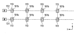
首先,如图40A所示,利用基于激光的测量设备等,来在地表上求出沿着x方向的两排直线131、132,在这些直线131、132上求出各桩子101的位置并进行标记。各桩子101的位置是在各个直线131、132上隔开与各基轨71、72的长度相同的间隔设定的。然后,将各桩子101打设于各个位置。此外,各桩子101的凸缘部101b被定位于高出地面30cm左右的高度位置,且大致水平。First, as shown in FIG. 40A, two rows of
如图40B(详细部分参照图37A~图39)所示,在各桩子101的凸缘部101b上搭载各个基轨连结部件113,按每个凸缘部101b,将四个螺栓121通过基轨连结部件113的底板113c的各长孔113d而拧入缘部101b的四个螺纹孔101c。由此,在两排直线131、132上,各基轨连结部件113隔开与各基轨71、72的长度相同的间隔被定位。As shown in FIG. 40B (see FIGS. 37A to 39 for details), each base
此时,将各螺栓121放松使其处于临时固定的状态,从而能够使基轨连结部件113向各长孔113d的长度方向、也就是y方向滑动。该y方向的移动范围取决于基轨连结部件113的各长孔113d的长度,例如为±50mm左右。At this time, each bolt 121 is loosened and temporarily fixed, and the base
如图40C(详细部分参照图37~图39)所示,在一方排131上的各基轨连结部件113间分别架设基轨71,按每个基轨71,将基轨71的底板71b的两端部搭载于各个基轨连结部件113的突边状平板部113a。然后,针对底板71b的两端部的任一端部,使底板71b的各长孔71c与突边状平板部113a的各螺纹孔113b重叠,将两根螺栓122通过底板71b的各长孔71c而拧入突边状平板部113a的各螺纹孔113b。As shown in Figure 40C (refer to Figures 37 to 39 for details), the base rails 71 are erected between the base
同样地,在另一方排132上的各基轨连结部件113间分别架设基轨72,按每个基轨72,将基轨72的底板72b的两端部搭载于各个基轨连结部件113的突边状平板部113a。然后,针对底板72b的两端部的任一端部,使底板72b的各长孔72c与突边状平板部113a的各螺纹孔113b重叠,将两根螺栓122通过底板72b的各长孔72c而拧入突边状平板部113a的各螺纹孔113b。Similarly, the base rails 72 are erected between the base
此时,将各螺栓122放松使其处于临时固定的状态,从而能够使各基轨71、72的端部向各长孔71c、72c的长度方向、也就是x方向滑动。该x方向的移动范围取决于各基轨71、72的各长孔71c、72c的长度,例如为±50mm左右。At this time, by loosening the bolts 122 and temporarily fixing them, the ends of the base rails 71, 72 can be slid in the longitudinal direction of the
在该状态下,由于能够使搭载各基轨71、72的端部的基轨连结部件113向y方向滑动,并且能够使各基轨71、72的端部向x方向滑动,因此能够使各基轨71、72的端部向xy方向移动。各基轨71、72的端部的移动范围在xy方向均为±50mm左右,成为用虚线表示的圆形的范围Q(图40E所示)。In this state, since the base
如图40D所示,针对彼此对置的每一对基轨71、72,在该各基轨71、72间配置支承杆123,并在该各基轨71、72的中央连接固定支承杆123的两端。此时,将支承杆123配置于与各基轨71、72正交的方向。由此,所有的各基轨71、72的分离距离变为恒定,如图33A~图33C所示的连接各基轨71而成的基轨111及连接各基轨72而成的基轨112的分离距离也变为恒定。As shown in FIG. 40D, for each pair of base rails 71, 72 facing each other, a
如图40E所示,将支柱124架设在第一个基轨71与第二个基轨72之间,并且架设在第二个基轨71与第一个基轨72之间进行固定。同样地,将支柱124架设在第二个基轨71与第三个基轨72之间,并且架设在第三个基轨71与第二个基轨72之间进行固定。As shown in FIG. 40E , the
支柱124是使两根杆倾斜地交叉后进行相互固定的。由于将该支柱124的各端部固定于第一个及第二个基轨71(或72),因此按照第一个及第二个基轨71(或72)的端部相互对接的方式定位。同样地,第二个与第三个基轨71(或72)的端部相互对接地被定位。The
此外,支柱124使各基轨71、72的分离距离恒定不变。基于该支柱124的分离距离,与基于支承杆123的分离距离相同。因此,第一个彼此对置的各基轨71、72平行,第二个彼此对置的各基轨71、72也平行。In addition, the
这样在定位第一个与第二个各基轨71、72之后,在这些基轨71、72的两端部侧,紧固各螺栓121,将基轨连结部件113固定于桩子101的凸缘部101b,并紧固各螺栓122,将各基轨71、72的两端部固定于基轨连结部件113的突边状平板部113a。由此,固定第一个及第二个各基轨71、72的两端部。In this way, after positioning the first and second base rails 71, 72, fasten the bolts 121 on both ends of the base rails 71, 72 to fix the base
接着,如图40F所示,取下架设在第一个基轨与第二个基轨之间的支柱124,将该支柱124架设到第三个基轨71与第四个基轨72之间,并且架设到第三个基轨71与第四个基轨72之间进行固定。即,使支柱124移动。Next, as shown in FIG. 40F , remove the
由此,第三个与第四个基轨71(或72)的端部相互对接地被定位。此外,第三个彼此对置的各基轨71、72平行,第四个彼此对置的各基轨71、72也平行。Thereby, the ends of the third and fourth base rails 71 (or 72 ) are positioned facing each other. Furthermore, the third base rails 71 , 72 facing each other are parallel, and the fourth base rails 71 , 72 facing each other are also parallel.
这样,在定位第三个与第四个各基轨71、72后,紧固这些基轨71、72的两端部侧的各螺栓121、122,从固定这些基轨71、72的两端部。In this way, after positioning the third and fourth base rails 71, 72, fasten the bolts 121, 122 on the two end sides of these base rails 71, 72 to fix the two ends of these base rails 71, 72. department.
之后,取下两个支柱124中位于左侧的支柱124,将该支柱124架设并固定到下一顺序的各基轨71、72,固定利用该支柱124首次定位的各基轨71、72的两端部,依次固定各基轨71、72。Afterwards, remove the
然后,如果固定到最后顺序的各基轨71、72的两端部,则取下各支柱124。此外,各支承杆123为了加强如图33A~图33C所示的较长的各基轨111,112而保留,不被取下。Then, if it is fixed to both end portions of each of the base rails 71 and 72 in the last order, each
按照这样的图40A~图40F的顺序,能够将图33A~图33C所示的较长的各基轨111、112隔开一定的分离距离并相互平行地配置,能够将各基轨111、112的突边状平板部设为平坦的基础面。According to the order of such FIGS. 40A to 40F, the longer base rails 111, 112 shown in FIGS. The flange-shaped flat plate portion is set as a flat base surface.
之后,按照图9~图16所示的顺序,将多个构造物设置支架10并排设置并固定于各基轨111、112上,进一步如图19以及图31所示,将太阳能电池模块2的端部固定于构造物设置支架10的载置用框架11上,从而设置多个太阳能电池模块2。Afterwards, according to the sequence shown in FIGS. 9 to 16, a plurality of
其中,本发明不限于上述实施方式,可进行各种变形。例如,虽然将载置用框架、纵框的截面形状设为帽型或大致U字型,但也可以设为C型等。However, the present invention is not limited to the above-described embodiments, and various modifications are possible. For example, although the cross-sectional shapes of the mounting frame and the vertical frame are hat-shaped or substantially U-shaped, they may be C-shaped or the like.
此外,本发明在不脱离其精神或主要特征的前提下,还可以以其他各种形式实施。因此,上述实施方式在所有观点上只是单纯的例示,不应限定地进行解释。本发明的范围由权利要求书的范围决定,不限于说明书本文。并且,属于权利要求范围的均等范围内的变形或变更,全部包含于本发明的范围内。In addition, the present invention can be implemented in other various forms without departing from the spirit or main characteristics thereof. Therefore, the above-mentioned embodiment is merely an illustration in all viewpoints, and should not interpret it limitedly. The scope of the present invention is determined by the scope of the claims, not limited by the text of the description. In addition, all modifications and changes that fall within the scope of equality of the claims are included in the scope of the present invention.
此外,本申请基于2008年12月5日在日本申请的特愿2008-311260请求优先权。通过引用,将其全部内容并入于本申请。In addition, this application claims priority based on Japanese Patent Application No. 2008-311260 filed on December 5, 2008 in Japan. The entire contents of which are incorporated into this application by reference.
产业上应用的可能性Possibility of industrial application
本发明能够应用到为了在地面或平屋顶等上设置太阳能电池模块等平板状的构造物而使用的构造物设置支架中。The present invention can be applied to a structure installation stand used to install a flat structure such as a solar cell module on the ground or a flat roof.
标号说明Label description
1太阳能电池系统1 solar battery system
2太阳能电池模块2 solar cell modules
3a、3b上部固定金属件3a, 3b upper fixing metal parts
4下部固定金属件4 lower fixing metal parts
10构造物设置支架10 structure setting bracket
11载置用框架11Frame for mounting
12顶板12 top plate
16纵框16 vertical frame
20太阳能电池面板20 solar panels
21框部件21 frame parts
71、72、111、112基轨71, 72, 111, 112 base rail
73前方托架73 front bracket
74后方托架74 rear bracket
75、77、83、85、121、122螺栓75, 77, 83, 85, 121, 122 bolts
91、92、93支柱91, 92, 93 pillars
101桩子101 stakes
113基轨连结部件113 base rail connecting parts
123支承杆123 support rod
124支柱124 pillars
Claims (8)
Applications Claiming Priority (3)
| Application Number | Priority Date | Filing Date | Title |
|---|---|---|---|
| JP2008-311260 | 2008-12-05 | ||
| JP2008311260A JP4562793B2 (en) | 2008-12-05 | 2008-12-05 | Structure installation stand and solar cell system |
| PCT/JP2009/070244 WO2010064656A1 (en) | 2008-12-05 | 2009-12-02 | Mount for installing structure, and solar cell system |
Publications (1)
| Publication Number | Publication Date |
|---|---|
| CN102239300A true CN102239300A (en) | 2011-11-09 |
Family
ID=42233303
Family Applications (1)
| Application Number | Title | Priority Date | Filing Date |
|---|---|---|---|
| CN200980148054XA Pending CN102239300A (en) | 2008-12-05 | 2009-12-02 | Mount for installing structure, and solar cell system |
Country Status (6)
| Country | Link |
|---|---|
| US (1) | US20110240101A1 (en) |
| EP (1) | EP2357297A1 (en) |
| JP (1) | JP4562793B2 (en) |
| CN (1) | CN102239300A (en) |
| AU (1) | AU2009323296A1 (en) |
| WO (1) | WO2010064656A1 (en) |
Cited By (1)
| Publication number | Priority date | Publication date | Assignee | Title |
|---|---|---|---|---|
| CN103208541A (en) * | 2012-01-12 | 2013-07-17 | 中电电气(上海)太阳能科技有限公司 | System for rapidly installing solar photovoltaic assembly and support |
Families Citing this family (30)
| Publication number | Priority date | Publication date | Assignee | Title |
|---|---|---|---|---|
| WO2010141740A2 (en) | 2009-06-05 | 2010-12-09 | First Solar, Inc. | Photovoltaic module ground mount |
| JP5393585B2 (en) * | 2010-05-12 | 2014-01-22 | 三菱電機株式会社 | Solar panel installation stand |
| WO2012018360A1 (en) | 2010-08-06 | 2012-02-09 | First Solar, Inc. | Folding mount for photovoltaic modules |
| IT1404053B1 (en) * | 2011-02-08 | 2013-11-08 | Zamet Spa | MODULAR RAPID MOUNTING SYSTEM FOR THE CONSTRUCTION OF SUPPORT STRUCTURES FOR SOLAR PANELS. |
| WO2012133991A1 (en) * | 2011-03-30 | 2012-10-04 | (주)아이파워 | Solar cell module support structure |
| JP5948598B2 (en) * | 2011-05-31 | 2016-07-06 | パナソニックIpマネジメント株式会社 | Solar power generation device and spacer for solar power generation device |
| CN102496640B (en) * | 2011-12-02 | 2013-10-30 | 苏州瑞得恩光能科技有限公司 | K-shaped support with angle-adjustable supporting surface |
| US20130200234A1 (en) * | 2012-02-06 | 2013-08-08 | First Solar, Inc. | Mounting clamp and mounting clamp configuration for photovoltaic module installation |
| DE202012101346U1 (en) * | 2012-04-13 | 2013-07-15 | Richard Brink Gmbh & Co. Kg | Kit of a holding device for solar elements |
| CN102790105B (en) * | 2012-08-13 | 2014-08-06 | 友达光电股份有限公司 | Solar module |
| WO2014039563A1 (en) | 2012-09-04 | 2014-03-13 | Stephan Erich Kai | Wear reduction system for rooftop mounts |
| CN102903772B (en) | 2012-09-26 | 2015-09-30 | 友达光电股份有限公司 | Solar energy equipment and its assembly system |
| CN103107219B (en) * | 2012-12-28 | 2015-07-29 | 友达光电股份有限公司 | Photovoltaic panel system, photovoltaic panel fixing device and method for installing photovoltaic panel system |
| US9303663B2 (en) | 2013-04-11 | 2016-04-05 | Northern States Metals Company | Locking rail alignment system |
| JP6033191B2 (en) * | 2013-09-09 | 2016-11-30 | シャープ株式会社 | Pile, pile installation jig, installation method of the pile, and solar power generation system using the pile |
| CA2830914C (en) * | 2013-10-11 | 2018-06-26 | Polar Racking Inc. | Support racking for solar panel |
| KR200480317Y1 (en) * | 2014-05-14 | 2016-05-18 | (주)코리아에너텍 | Module mounting assembly supporting device of condensing unit |
| JP6573485B2 (en) * | 2015-06-01 | 2019-09-11 | 旭化成ホームズ株式会社 | Fixed member |
| JP6343810B2 (en) * | 2016-03-18 | 2018-06-20 | パナソニックIpマネジメント株式会社 | Solar power generation device and spacer for solar power generation device |
| US10256768B2 (en) * | 2016-04-25 | 2019-04-09 | Cmco Solar, Llc | Photovoltaic array mounting structure |
| US9628019B1 (en) * | 2016-09-09 | 2017-04-18 | Polar Racking Inc. | Photovoltaic panel racking system |
| US11271518B2 (en) | 2018-11-08 | 2022-03-08 | OMCO Solar, LLC | Mounting bracket for mounting photovoltaic modules to torque tube beam |
| US11848636B2 (en) | 2019-06-04 | 2023-12-19 | Pegasus Solar, Inc. | Skip rail system |
| US12292075B2 (en) | 2019-11-25 | 2025-05-06 | Pegasus Solar Inc | Twist-lock solar module clamp |
| US11377840B2 (en) | 2019-11-26 | 2022-07-05 | Pegasus Solar Inc. | One-piece bonding splice for rails |
| USD1004141S1 (en) | 2020-12-01 | 2023-11-07 | Pegasus Solar, Inc. | Rail |
| US11990862B2 (en) | 2021-02-18 | 2024-05-21 | Pegasus Solar Inc. | Rail accessory mount |
| US12281750B2 (en) | 2022-01-14 | 2025-04-22 | Pegasus Solar Inc | Grip rail clamp |
| JP7847367B2 (en) * | 2022-04-12 | 2026-04-17 | 株式会社ベルテック | Solar panel installation device and solar panel installation method |
| FR3155392B1 (en) * | 2023-11-09 | 2025-10-31 | Beem | adjustable photovoltaic system |
Citations (8)
| Publication number | Priority date | Publication date | Assignee | Title |
|---|---|---|---|---|
| JPH11177115A (en) * | 1997-12-12 | 1999-07-02 | Ntt Power And Building Facilities Inc | Mounting stand for solar cell module |
| JP2000101123A (en) * | 1998-09-25 | 2000-04-07 | Aichi Electric Co Ltd | Solar cell mounting base device |
| CN1622343A (en) * | 2003-11-28 | 2005-06-01 | 夏普株式会社 | Solar cell module edge face sealing member and solar cell module employing same |
| JP3748445B2 (en) * | 2003-11-20 | 2006-02-22 | 株式会社ブレスト工業研究所 | Base rail fixing device for solar cell module mounting |
| JP2006210613A (en) * | 2005-01-27 | 2006-08-10 | Kyocera Corp | Solar power plant |
| CN101151429A (en) * | 2005-04-07 | 2008-03-26 | 夏普株式会社 | Installation structure of solar cell module |
| JP2008208554A (en) * | 2007-02-23 | 2008-09-11 | Sharp Corp | Structure installation stand |
| JP2008214875A (en) * | 2007-02-28 | 2008-09-18 | Sharp Corp | Mounting structure of solar cell module |
Family Cites Families (4)
| Publication number | Priority date | Publication date | Assignee | Title |
|---|---|---|---|---|
| JPH0970188A (en) * | 1995-08-30 | 1997-03-11 | Nissin Electric Co Ltd | Solar panel installation structure |
| JPH1051019A (en) * | 1996-07-29 | 1998-02-20 | Toshiba Corp | Solar array |
| JP2004140256A (en) * | 2002-10-18 | 2004-05-13 | Mitsubishi Heavy Ind Ltd | Solar cell panel installing structure |
| JP2008311260A (en) | 2007-06-12 | 2008-12-25 | Panasonic Corp | Manufacturing method of semiconductor device |
-
2008
- 2008-12-05 JP JP2008311260A patent/JP4562793B2/en not_active Expired - Fee Related
-
2009
- 2009-12-02 EP EP09830422A patent/EP2357297A1/en not_active Withdrawn
- 2009-12-02 US US13/133,011 patent/US20110240101A1/en not_active Abandoned
- 2009-12-02 CN CN200980148054XA patent/CN102239300A/en active Pending
- 2009-12-02 AU AU2009323296A patent/AU2009323296A1/en not_active Abandoned
- 2009-12-02 WO PCT/JP2009/070244 patent/WO2010064656A1/en not_active Ceased
Patent Citations (8)
| Publication number | Priority date | Publication date | Assignee | Title |
|---|---|---|---|---|
| JPH11177115A (en) * | 1997-12-12 | 1999-07-02 | Ntt Power And Building Facilities Inc | Mounting stand for solar cell module |
| JP2000101123A (en) * | 1998-09-25 | 2000-04-07 | Aichi Electric Co Ltd | Solar cell mounting base device |
| JP3748445B2 (en) * | 2003-11-20 | 2006-02-22 | 株式会社ブレスト工業研究所 | Base rail fixing device for solar cell module mounting |
| CN1622343A (en) * | 2003-11-28 | 2005-06-01 | 夏普株式会社 | Solar cell module edge face sealing member and solar cell module employing same |
| JP2006210613A (en) * | 2005-01-27 | 2006-08-10 | Kyocera Corp | Solar power plant |
| CN101151429A (en) * | 2005-04-07 | 2008-03-26 | 夏普株式会社 | Installation structure of solar cell module |
| JP2008208554A (en) * | 2007-02-23 | 2008-09-11 | Sharp Corp | Structure installation stand |
| JP2008214875A (en) * | 2007-02-28 | 2008-09-18 | Sharp Corp | Mounting structure of solar cell module |
Cited By (2)
| Publication number | Priority date | Publication date | Assignee | Title |
|---|---|---|---|---|
| CN103208541A (en) * | 2012-01-12 | 2013-07-17 | 中电电气(上海)太阳能科技有限公司 | System for rapidly installing solar photovoltaic assembly and support |
| CN103208541B (en) * | 2012-01-12 | 2015-09-09 | 中电电气(上海)太阳能科技有限公司 | The system of a kind of Fast Installation solar photovoltaic assembly and support |
Also Published As
| Publication number | Publication date |
|---|---|
| US20110240101A1 (en) | 2011-10-06 |
| JP4562793B2 (en) | 2010-10-13 |
| WO2010064656A1 (en) | 2010-06-10 |
| JP2010135632A (en) | 2010-06-17 |
| AU2009323296A1 (en) | 2011-06-30 |
| EP2357297A1 (en) | 2011-08-17 |
Similar Documents
| Publication | Publication Date | Title |
|---|---|---|
| JP4562793B2 (en) | Structure installation stand and solar cell system | |
| JP5912100B2 (en) | Solar power panel | |
| JP4637231B2 (en) | Solar cell module installation stand | |
| JP4202401B1 (en) | Structure installation stand, its assembling method, solar cell module, and construction structure using structure installation stand | |
| US20130098858A1 (en) | Support system for solar panels with modified joists | |
| CN103107219A (en) | Photovoltaic panel system, photovoltaic panel fixing device and method for installing photovoltaic panel system | |
| JP5079919B2 (en) | Planar body support frame and solar power generation device | |
| WO2011136350A1 (en) | Planar support frame and solar power generation device | |
| JP5622709B2 (en) | Supporting frame structure for photovoltaic panel frame | |
| WO2012121147A1 (en) | Mounting base for solar cell module, method for constructing mounting base, and solar photovoltaic power generation system with mounting base | |
| JP6409225B2 (en) | Structure installation stand and its construction method | |
| JP2014148822A (en) | Installation device of solar battery array to folded-plate roof | |
| JP2014101635A (en) | Foundation unit and frame | |
| JP5956214B2 (en) | Foundation structure for the solar cell module support | |
| JP5472535B2 (en) | Panel support base | |
| JP2014212177A (en) | Installation device of solar battery array | |
| JP2014088708A (en) | Mounting rack for photovoltaic generation module and photovoltaic generation device | |
| JP2011106203A (en) | Mounting base of outdoor structure | |
| JP3181778U (en) | Photovoltaic panel support stand | |
| JP6346755B2 (en) | Solar power panel | |
| JP2014148820A (en) | Installation device of solar battery array | |
| JP2014148821A (en) | Solar battery array installation device | |
| JP3182262U (en) | Solar cell module mount | |
| KR20220152491A (en) | Frame Structure for Solar Panel Installation | |
| KR102804052B1 (en) | Supporting structure for building rooftop constructed by modules |
Legal Events
| Date | Code | Title | Description |
|---|---|---|---|
| C06 | Publication | ||
| PB01 | Publication | ||
| C10 | Entry into substantive examination | ||
| SE01 | Entry into force of request for substantive examination | ||
| WD01 | Invention patent application deemed withdrawn after publication |
Application publication date: 20111109 |
|
| WD01 | Invention patent application deemed withdrawn after publication |