CN102214439A - Light emitting device, electronic apparatus, and driving method of light emitting device - Google Patents
Light emitting device, electronic apparatus, and driving method of light emitting device Download PDFInfo
- Publication number
- CN102214439A CN102214439A CN2011100847921A CN201110084792A CN102214439A CN 102214439 A CN102214439 A CN 102214439A CN 2011100847921 A CN2011100847921 A CN 2011100847921A CN 201110084792 A CN201110084792 A CN 201110084792A CN 102214439 A CN102214439 A CN 102214439A
- Authority
- CN
- China
- Prior art keywords
- mentioned
- light
- circuit
- electrode
- emitting component
- Prior art date
- Legal status (The legal status is an assumption and is not a legal conclusion. Google has not performed a legal analysis and makes no representation as to the accuracy of the status listed.)
- Pending
Links
Images


Classifications
-
- G—PHYSICS
- G09—EDUCATION; CRYPTOGRAPHY; DISPLAY; ADVERTISING; SEALS
- G09G—ARRANGEMENTS OR CIRCUITS FOR CONTROL OF INDICATING DEVICES USING STATIC MEANS TO PRESENT VARIABLE INFORMATION
- G09G3/00—Control arrangements or circuits, of interest only in connection with visual indicators other than cathode-ray tubes
- G09G3/20—Control arrangements or circuits, of interest only in connection with visual indicators other than cathode-ray tubes for presentation of an assembly of a number of characters, e.g. a page, by composing the assembly by combination of individual elements arranged in a matrix no fixed position being assigned to or needed to be assigned to the individual characters or partial characters
- G09G3/22—Control arrangements or circuits, of interest only in connection with visual indicators other than cathode-ray tubes for presentation of an assembly of a number of characters, e.g. a page, by composing the assembly by combination of individual elements arranged in a matrix no fixed position being assigned to or needed to be assigned to the individual characters or partial characters using controlled light sources
- G09G3/30—Control arrangements or circuits, of interest only in connection with visual indicators other than cathode-ray tubes for presentation of an assembly of a number of characters, e.g. a page, by composing the assembly by combination of individual elements arranged in a matrix no fixed position being assigned to or needed to be assigned to the individual characters or partial characters using controlled light sources using electroluminescent panels
- G09G3/32—Control arrangements or circuits, of interest only in connection with visual indicators other than cathode-ray tubes for presentation of an assembly of a number of characters, e.g. a page, by composing the assembly by combination of individual elements arranged in a matrix no fixed position being assigned to or needed to be assigned to the individual characters or partial characters using controlled light sources using electroluminescent panels semiconductive, e.g. using light-emitting diodes [LED]
- G09G3/3208—Control arrangements or circuits, of interest only in connection with visual indicators other than cathode-ray tubes for presentation of an assembly of a number of characters, e.g. a page, by composing the assembly by combination of individual elements arranged in a matrix no fixed position being assigned to or needed to be assigned to the individual characters or partial characters using controlled light sources using electroluminescent panels semiconductive, e.g. using light-emitting diodes [LED] organic, e.g. using organic light-emitting diodes [OLED]
- G09G3/3225—Control arrangements or circuits, of interest only in connection with visual indicators other than cathode-ray tubes for presentation of an assembly of a number of characters, e.g. a page, by composing the assembly by combination of individual elements arranged in a matrix no fixed position being assigned to or needed to be assigned to the individual characters or partial characters using controlled light sources using electroluminescent panels semiconductive, e.g. using light-emitting diodes [LED] organic, e.g. using organic light-emitting diodes [OLED] using an active matrix
- G09G3/3233—Control arrangements or circuits, of interest only in connection with visual indicators other than cathode-ray tubes for presentation of an assembly of a number of characters, e.g. a page, by composing the assembly by combination of individual elements arranged in a matrix no fixed position being assigned to or needed to be assigned to the individual characters or partial characters using controlled light sources using electroluminescent panels semiconductive, e.g. using light-emitting diodes [LED] organic, e.g. using organic light-emitting diodes [OLED] using an active matrix with pixel circuitry controlling the current through the light-emitting element
-
- G—PHYSICS
- G09—EDUCATION; CRYPTOGRAPHY; DISPLAY; ADVERTISING; SEALS
- G09G—ARRANGEMENTS OR CIRCUITS FOR CONTROL OF INDICATING DEVICES USING STATIC MEANS TO PRESENT VARIABLE INFORMATION
- G09G2300/00—Aspects of the constitution of display devices
- G09G2300/02—Composition of display devices
- G09G2300/023—Display panel composed of stacked panels
-
- G—PHYSICS
- G09—EDUCATION; CRYPTOGRAPHY; DISPLAY; ADVERTISING; SEALS
- G09G—ARRANGEMENTS OR CIRCUITS FOR CONTROL OF INDICATING DEVICES USING STATIC MEANS TO PRESENT VARIABLE INFORMATION
- G09G2300/00—Aspects of the constitution of display devices
- G09G2300/04—Structural and physical details of display devices
- G09G2300/0421—Structural details of the set of electrodes
- G09G2300/0426—Layout of electrodes and connections
-
- G—PHYSICS
- G09—EDUCATION; CRYPTOGRAPHY; DISPLAY; ADVERTISING; SEALS
- G09G—ARRANGEMENTS OR CIRCUITS FOR CONTROL OF INDICATING DEVICES USING STATIC MEANS TO PRESENT VARIABLE INFORMATION
- G09G2300/00—Aspects of the constitution of display devices
- G09G2300/08—Active matrix structure, i.e. with use of active elements, inclusive of non-linear two terminal elements, in the pixels together with light emitting or modulating elements
- G09G2300/0809—Several active elements per pixel in active matrix panels
- G09G2300/0842—Several active elements per pixel in active matrix panels forming a memory circuit, e.g. a dynamic memory with one capacitor
-
- G—PHYSICS
- G09—EDUCATION; CRYPTOGRAPHY; DISPLAY; ADVERTISING; SEALS
- G09G—ARRANGEMENTS OR CIRCUITS FOR CONTROL OF INDICATING DEVICES USING STATIC MEANS TO PRESENT VARIABLE INFORMATION
- G09G2330/00—Aspects of power supply; Aspects of display protection and defect management
- G09G2330/02—Details of power systems and of start or stop of display operation
- G09G2330/021—Power management, e.g. power saving
-
- G—PHYSICS
- G09—EDUCATION; CRYPTOGRAPHY; DISPLAY; ADVERTISING; SEALS
- G09G—ARRANGEMENTS OR CIRCUITS FOR CONTROL OF INDICATING DEVICES USING STATIC MEANS TO PRESENT VARIABLE INFORMATION
- G09G2360/00—Aspects of the architecture of display systems
- G09G2360/04—Display device controller operating with a plurality of display units
-
- H—ELECTRICITY
- H10—SEMICONDUCTOR DEVICES; ELECTRIC SOLID-STATE DEVICES NOT OTHERWISE PROVIDED FOR
- H10K—ORGANIC ELECTRIC SOLID-STATE DEVICES
- H10K59/00—Integrated devices, or assemblies of multiple devices, comprising at least one organic light-emitting element covered by group H10K50/00
- H10K59/10—OLED displays
- H10K59/12—Active-matrix OLED [AMOLED] displays
- H10K59/128—Active-matrix OLED [AMOLED] displays comprising two independent displays, e.g. for emitting information from two major sides of the display
Abstract
The invention relates to a light emitting device, an electronic apparatus, and a driving method of the light emitting device. The light emitting device 10 includes a pixel circuit (P) and a driving circuit (20). The pixel circuit has a first circuit (Tp) provided correspondingly to a first power supply line (15) and a second circuit (Bp) provided correspondingly to a second power supply line (16). In a case where while an image is displayed on the first substrate side, an image is not displayed on the second substrate side, the value of the potential which is supplied to the second electric supply line, to be a value where voltage between both ends of the second light-emitting element falls below the light-emitting threshold voltage. In a case where while an image is not displayed on the first substrate side, an image is displayed on the second substrate side, the value of the potential which is supplied to the first electric supply line, to be a value where voltage between both ends of the first light-emitting element falls below the light-emitting threshold voltage.
Description
Technical field
The present invention relates to the driving method of light-emitting device and electronic equipment, light-emitting device.
Background technology
In recent years, the various light-emitting devices that use light-emitting component have been proposed, this light-emitting component comprises and is called as organic EL (Electro Luminescent: the electroluminescence) Organic Light Emitting Diode of element and light emitting polymer element etc. (Organic Light Emitting Diode: Organic Light Emitting Diode, back are called " OLED ") element etc.
For example, in patent documentation 1, disclose a kind of light-emitting device, this light-emitting device optionally makes in main panel (front display) and the subpanel (back displays device) any luminous.In patent documentation 1 disclosed light-emitting device, have to a plurality of sweep traces of main panel and supply with the main sweep drive division of selecting signal successively, supply with the subscan drive division of selecting signal successively, supply with drive control part with the action of the data-driven portion of the corresponding data voltage of picture signal and control light-emitting device to main panel and many total data lines of subpanel to a plurality of sweep traces of subpanel.Drive control part carries out following control: the limit makes the action of data-driven portion, and the limit makes any action in main sweep drive division and the subscan drive division.
Patent documentation 1: TOHKEMY 2006-58893 communique
In patent documentation 1 disclosed light-emitting device, the formation of the image element circuit of main panel is identical with the formation of the image element circuit of subpanel, all adopts the formation of Figure 18.As shown in figure 18, image element circuit is constituted as driving transistors DM, the light-emitting component OLED that comprises the P channel-type, the switching transistor SM and the capacitor Cst of P channel-type.At the hot side supply lines that has been supplied to hot side power supply potential VDD and be supplied between the low potential side supply lines of low potential side power supply potential VSS, driving transistors DM and light-emitting component OLED have been connected in series with each other.The hot side supply lines jointly is connected with respect to each image element circuit of main panel and subpanel respectively with the low potential side supply lines.Between the grid of driving transistors DM and source electrode, be provided with capacitor Cst.Switching transistor SM is arranged between the grid and data line D of driving transistors DM, and its grid is connected with sweep trace S.Switching transistor SM is controlled as conducting according to the selection signal to sweep trace S output or ends.
Be assumed to now and make main panel luminous and make the non-luminous situation of subpanel.In this case, because not to selecting signal, so the switching transistor SM of the image element circuit of subpanel maintains cut-off state with the corresponding sweep trace S output of the image element circuit of subpanel.Therefore, the data voltage that outputs to data line D does not supply to the grid of driving transistors DM of the image element circuit of subpanel.Here, owing to keeping in the last time of this image element circuit the data voltage that is written into when luminous among the capacitor Cst of the image element circuit of subpanel, so driving transistors DM is a conducting state.Hot side power lead and low potential side power lead jointly are connected on each image element circuit of main panel and subpanel, because the voltage between hot side power lead and the low potential side power lead is configured to the value greater than the lasing threshold voltage of light-emitting component OLED, thus in the light-emitting component of the image element circuit of subpanel, flow through with capacitor Cst in the corresponding electric current of data voltage that keeps.Therefore, be difficult to make and non-luminous panel (being subpanel) reach not luminance reliably here, and the problem that electric power is consumed in vain can take place.This problem makes subpanel luminous and make under the non-luminous situation of main panel and can take place too.
In addition, also can suppose following situation, light-emitting data makes capacitor Cst keep non-luminous voltage to make the non-luminous situation of subpanel thereby promptly write not by the image element circuit to subpanel one side.But, in this case,, be offset non-luminous data voltage because the leakage current of switching transistor SM can cause the voltage change of capacitor Cst, still can't solve and be difficult to keep reliably the not problem of luminance.
Summary of the invention
Situation in view of above the objective of the invention is to, and only in arbitrary luminous light-emitting device, makes and reduce power consumption simultaneously for non-luminous face is in not luminance reliably in one side that optionally makes panel and another side.
In order to solve above-mentioned problem, light-emitting device of the present invention is characterised in that to possess image element circuit that is configured on the substrate and the driving circuit that drives image element circuit, and image element circuit possesses: the 1st circuit, corresponding the 1st supply lines of the 1st circuit and being provided with; With the 2nd circuit, corresponding the 2nd supply lines of the 2nd circuit and being provided with, the 1st circuit comprises: the 1st light-emitting component, its have the 1st electrode (the 1st pixel electrode 61) that is electrically connected with the 1st supply lines and with the 2nd electrode (opposite electrode 90) of the 1st electrode contraposition; The 1st driving transistors, the 1st driving transistors is electrically connected with the 1st electrode; The 1st capacity cell, the 1st capacity cell are used to keep the current potential of the grid of the 1st driving transistors; With the 1st on-off element, the 1st on-off element is set between the grid and data line of the 1st driving transistors, the ejaculation light of the 1st light-emitting component penetrates from the one side side of substrate, the 2nd circuit comprises: the 2nd light-emitting component, the 2nd light-emitting component have the 3rd electrode (the 2nd pixel electrode 62) that is electrically connected with the 2nd supply lines and with the 2nd electrode of the 3rd electrode contraposition; The 2nd driving transistors, the 2nd driving transistors is electrically connected with the 3rd electrode; The 2nd capacity cell, the 2nd capacity cell are used to keep the current potential of the grid of the 2nd driving transistors; With the 2nd on-off element, the 2nd on-off element is set between the grid and data line of the 2nd driving transistors, the ejaculation light of the 2nd light-emitting component penetrates from the another side side of substrate, in the one side side of substrate by the 1st circuit display image and in the another side side of substrate not under the situation of display image, driving circuit is to data line output and the corresponding data current potential of view data, and be to make the 1st electrode of the 1st light-emitting component and the voltage between the 2nd electrode, and be to make the 3rd electrode of the 2nd light-emitting component and the voltage between the 2nd electrode value less than the lasing threshold voltage of the 2nd light-emitting component with the potential setting of the 2nd supply lines greater than the value of the lasing threshold voltage of the 1st light-emitting component with the potential setting of the 1st supply lines; The one side side of substrate not display image and in the another side side of substrate by under the situation of the 2nd circuit display image, driving circuit is to data line output data current potential, and be to make the 1st electrode of the 1st light-emitting component and the voltage between the 2nd electrode less than the value of the lasing threshold voltage of the 1st light-emitting component with the potential setting of the 1st supply lines, be to make the 3rd electrode of the 2nd light-emitting component and the voltage between the 2nd electrode value with the potential setting of the 2nd supply lines greater than the lasing threshold voltage of the 2nd light-emitting component.
In the present invention, the 1st circuit of the image that shows to the one side side that is used to be created on substrate from different power leads and being used to the 2nd circuit supply line voltage respectively that generates the image that the another side side of substrate shows.Since in the one side side of substrate by the 1st circuit display image and in the another side side of substrate not under the situation of display image, driving circuit becomes to make the 3rd electrode of the 2nd light-emitting component and the voltage between the 2nd electrode less than the value of the lasing threshold voltage of the 2nd light-emitting component, so can not flow through electric current in the 2nd light-emitting component the potential setting of the 2nd supply lines.So, can make the another side side of substrate be in not luminance reliably, and compare with the mode of jointly supplying with to the 1st circuit and the 2nd circuit greater than the supply voltage of the lasing threshold voltage separately of the 1st light-emitting component and the 2nd light-emitting component, can reduce power consumption.
In addition, since the one side side of substrate not display image and in the another side side of substrate by under the situation of the 2nd circuit display image, driving circuit becomes to make the 1st electrode of the 1st light-emitting component and the voltage between the 2nd electrode less than the value of the lasing threshold voltage of the 1st light-emitting component the potential setting of the 1st supply lines, therefore can not flow through electric current in the 1st light-emitting component.So, can make the one side side of substrate be in not luminance reliably, and compare with the mode of jointly supplying with to the 1st circuit and the 2nd circuit greater than the supply voltage of the lasing threshold voltage separately of the 1st light-emitting component and the 2nd light-emitting component, can reduce power consumption.That is,, has following advantage: can make not that the face of emission side is in not luminance reliably, can reduce light-emitting device power consumption simultaneously according to the present invention.
Embodiment as light-emitting device of the present invention, in the one side side of substrate by the 1st circuit display image and in the another side side of substrate not under the situation of display image, driving circuit is set the 1st on-off element for conducting state, set the 2nd on-off element for cut-off state, the one side side of substrate not display image and in the another side side of substrate by under the situation of the 2nd circuit display image, driving circuit is set the 1st on-off element for cut-off state, sets the 2nd on-off element for conducting state.But be not limited thereto, also can constitute: though in the one side side of substrate by the 1st circuit display image and in the another side side of substrate not under the situation of display image, driving circuit is also set the 2nd on-off element for conducting state, even the one side side of substrate not display image and in the another side side of substrate by under the situation of the 2nd circuit display image, driving circuit is also set the 1st on-off element for conducting state.
In addition, light-emitting device of the present invention is characterised in that to possess: a plurality of the 1st sweep traces, and these a plurality of the 1st sweep traces extend in the 1st direction respectively; A plurality of the 2nd sweep traces, these a plurality of the 2nd sweep traces and a plurality of the 1st sweep trace are provided with correspondingly; A plurality of data lines, these a plurality of data lines extend in the 2nd direction different with the 1st direction respectively; Each point of crossing that a plurality of image element circuits, the corresponding a plurality of data lines of these a plurality of image element circuits and a plurality of the 1st sweep traces and the 2nd sweep trace intersect and disposing; And driving circuit, this driving circuit drives above-mentioned each image element circuit, each image element circuit is configured on the substrate, and possess corresponding and the 1st circuit that is provided with and and 2nd circuit setting corresponding with the 2nd supply lines with the 1st supply lines, the 1st circuit comprises: the 1st light-emitting component, the 1st light-emitting component have the 1st electrode that is electrically connected with the 1st supply lines and with the 2nd electrode of the 1st electrode contraposition; The 1st driving transistors, the 1st driving transistors is electrically connected with the 1st electrode; The 1st capacity cell, the 1st capacity cell are used to keep the current potential of the grid of the 1st driving transistors; With the 1st on-off element, the 1st on-off element is set between the grid and data line of the 1st driving transistors, and when the 1st sweep trace is selected, make the grid and the data line conducting of the 1st driving transistors, the ejaculation light of the 1st light-emitting component penetrates from the one side side of substrate, the 2nd circuit comprises: the 2nd light-emitting component, the 2nd light-emitting component have the 3rd electrode that is electrically connected with the 2nd supply lines and with the 2nd electrode of the 3rd electrode contraposition; The 2nd driving transistors, the 2nd driving transistors is electrically connected with the 3rd electrode; The 2nd capacity cell, the 2nd capacity cell are used to keep the current potential of the grid of the 2nd driving transistors; With the 2nd on-off element, the 2nd on-off element is set between the grid and data line of the 2nd driving transistors, and when the 2nd sweep trace is selected, make the grid and the data line conducting of the 2nd driving transistors, the ejaculation light of the 2nd light-emitting component penetrates from the another side side of substrate, in the one side side of substrate by the 1st circuit display image and in the another side side of substrate not under the situation of display image, select each the 1st sweep trace successively during driving circuit is selected by each and do not select each the 2nd sweep trace, to each data line output and the corresponding data current potential of view data, and be to make the 1st electrode of the 1st light-emitting component and the voltage between the 2nd electrode, and be to make the 3rd electrode of the 2nd light-emitting component and the voltage between the 2nd electrode value less than the lasing threshold voltage of the 2nd light-emitting component with the potential setting of the 2nd supply lines greater than the value of the lasing threshold voltage of the 1st light-emitting component with the potential setting of the 1st supply lines; The one side side of substrate not display image and in the another side side of substrate by under the situation of the 2nd circuit display image, select each the 2nd sweep trace successively during driving circuit is selected by each and do not select each the 1st sweep trace, to data line output data current potential, and be to make the 1st electrode of the 1st light-emitting component and the voltage between the 2nd electrode less than the value of the lasing threshold voltage of the 1st light-emitting component with the potential setting of the 1st supply lines, be to make the 3rd electrode of the 2nd light-emitting component and the voltage between the 2nd electrode value with the potential setting of the 2nd supply lines greater than the lasing threshold voltage of the 2nd light-emitting component.
In above-mentioned the present invention, in each image element circuit, the 2nd circuit that the 1st circuit of the image that shows to the one side side that is used to be created on substrate from different power leads and being used to is created on the image that the another side side of substrate shows is supply line voltage respectively.And, in the one side side of substrate by the 1st circuit display image and in the another side side of substrate not under the situation of display image, driving circuit does not drive each the 2nd circuit, but become to make the 3rd electrode of the 2nd light-emitting component and the voltage between the 2nd electrode less than the value of the lasing threshold voltage of the 2nd light-emitting component the potential setting of the 2nd supply lines, therefore in the 2nd light-emitting component, can not flow through electric current.So, can make the another side side of substrate be in not luminance reliably, and compare with the mode of jointly supplying with to each the 1st circuit and Ge Di 2 circuit greater than the supply voltage of the lasing threshold voltage separately of the 1st light-emitting component and the 2nd light-emitting component, can reduce power consumption.
In addition, the one side side of substrate not display image and in the another side side of substrate by under the situation of the 2nd circuit display image, driving circuit does not drive each the 1st circuit, but become to make the 1st electrode of the 1st light-emitting component and the voltage between the 2nd electrode less than the value of the lasing threshold voltage of the 1st light-emitting component the potential setting of the 1st supply lines, therefore in the 1st light-emitting component, can not flow through electric current.So, can make the one side side of substrate be in not luminance reliably, and compare with the mode of jointly supplying with to each the 1st circuit and Ge Di 2 circuit greater than the supply voltage of the lasing threshold voltage separately of the 1st light-emitting component and the 2nd light-emitting component, can reduce power consumption.That is,, has following advantage: can make and be in not luminance reliably by non-luminous face, can reduce light-emitting device power consumption simultaneously according to the present invention.
Light-emitting device of the present invention is used to various electronic equipments.The typical example of electronic equipment has the equipment of light-emitting device as display device.As electronic equipment of the present invention, illustration personal computer and mobile phone.
The present invention also is confirmed as the method for driven for emitting lights device.The driving method that the present invention relates to is used for the light-emitting device of following formation, this light-emitting device constitutes possesses image element circuit that is configured on the substrate and the driving circuit that drives image element circuit, image element circuit possesses: the 1st circuit, corresponding the 1st supply lines of the 1st circuit and being provided with; With the 2nd circuit, corresponding the 2nd supply lines of the 2nd circuit and being provided with, the 1st circuit comprises: the 1st light-emitting component, the 1st light-emitting component have the 1st electrode that is electrically connected with the 1st supply lines and with the 2nd electrode of the 1st electrode contraposition; The 1st driving transistors, the 1st driving transistors is electrically connected with the 1st electrode; With the 1st capacity cell, the 1st capacity cell is used to keep the current potential of the grid of the 1st driving transistors, the ejaculation light of the 1st light-emitting component penetrates from the one side side of substrate, the 2nd circuit comprises: the 2nd light-emitting component, the 2nd light-emitting component have the 3rd electrode that is electrically connected with the 2nd supply lines and with the 2nd electrode of the 3rd electrode contraposition; The 2nd driving transistors, the 2nd driving transistors is electrically connected with the 3rd electrode; With the 2nd capacity cell, the 2nd capacity cell is used to keep the current potential of the grid of the 2nd driving transistors, the ejaculation light of the 2nd light-emitting component penetrates from the another side side of substrate, driving method according to this light-emitting device, in the one side side of substrate by the 1st circuit display image and in the another side side of substrate not under the situation of display image, the potential setting of the grid of the 1st driving transistors is become and the corresponding data current potential of view data, with the potential setting of the 1st supply lines is to make the 1st electrode of the 1st light-emitting component and the voltage between the 2nd electrode greater than the value of the lasing threshold voltage of the 1st light-emitting component, is to make the 3rd electrode of the 2nd light-emitting component and the voltage between the 2nd electrode value less than the lasing threshold voltage of the 2nd light-emitting component with the potential setting of the 2nd supply lines; The one side side of substrate not display image and in the another side side of substrate by under the situation of the 2nd circuit display image, to data line output data current potential, with the potential setting of the 1st supply lines is to make the 1st electrode of the 1st light-emitting component and the voltage between the 2nd electrode less than the value of the lasing threshold voltage of the 1st light-emitting component, is to make the 3rd electrode of the 2nd light-emitting component and the voltage between the 2nd electrode value greater than the lasing threshold voltage of the 2nd light-emitting component with the potential setting of the 2nd supply lines.Also can access the effect same by above driving method with light-emitting device of the present invention.
Description of drawings
Fig. 1 is the square block scheme of the light-emitting device of embodiments of the present invention.
Fig. 2 is the circuit diagram of signal selecting circuit.
Fig. 3 is the circuit diagram of power supply switch circuit.
Fig. 4 is the circuit diagram of image element circuit.
Fig. 5 is the sectional view of image element circuit.
Fig. 6 is used to illustrate at the 1st substrate-side display image and at the 2nd substrate-side figure of the action of the signal selecting circuit under the situation of display image not.
Fig. 7 is used to illustrate at the 1st substrate-side display image and at the 2nd substrate-side figure of the action of the power supply switch circuit under the situation of display image not.
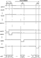
Fig. 8 is used to illustrate at the 1st substrate-side display image and at the 2nd substrate-side sequential chart of the concrete action of the light-emitting device under the situation of display image not.
Fig. 9 is used to illustrate at the 1st substrate-side display image and at the 2nd substrate-side figure of the action of the image element circuit under the situation of display image not.
Figure 10 is used to illustrate at the 2nd substrate-side display image and at the 1st substrate-side figure of the action of the signal selecting circuit under the situation of display image not.
Figure 11 is used to illustrate at the 2nd substrate-side display image and at the 1st substrate-side figure of the action of the power supply switch circuit under the situation of display image not.
Figure 12 is used to illustrate at the 2nd substrate-side display image and at the 1st substrate-side sequential chart of the concrete action of the light-emitting device under the situation of display image not.
Figure 13 is used to illustrate at the 2nd substrate-side display image and at the 1st substrate-side figure of the action of the image element circuit under the situation of display image not.
Figure 14 is the circuit diagram of the image element circuit of variation of the present invention.
Figure 15 is the stereographic map of the concrete mode of expression electronic equipment of the present invention.
Figure 16 is the stereographic map of the concrete mode of expression electronic equipment of the present invention.
Figure 17 is the stereographic map of the concrete mode of expression electronic equipment of the present invention.
Figure 18 is the figure of the formation of the image element circuit in the existing light-emitting device of expression.
Symbol description among the figure:
10... element portion; 11... the 1st sweep trace; 12... the 2nd sweep trace; 13... sweep trace; 14... data line; 15... the 1st supply lines; 16... the 2nd supply lines; 17... the 3rd supply lines; 20... driving circuit; 21... the 1st scan line drive circuit; 22... the 2nd scan line drive circuit; 23... data line drive circuit; 24... power circuit; 25... control circuit; 30... signal selecting circuit; 31... the 1st substrate; 32... the 2nd substrate; 40... power supply switch circuit; 100... light-emitting device; P... image element circuit; Tp... the 1st circuit; Bp... the 2nd circuit; E1... the 1st light-emitting component; E2... the 2nd light-emitting component; DrT... the 1st driving transistors; DrB... the 2nd driving transistors; C1... the 1st capacity cell; C2... the 2nd capacity cell; GT... the 1st on-off element; GB... the 2nd on-off element; GWT... the 1st sweep signal; GWB... the 2nd sweep signal; VX... data current potential; H... horizontal scan period; Tr1~Tr8... transistor; IV1~4V4... phase inverter; SP, SPT, SPB... starting impulse, SEL... select signal.
Embodiment
<A: embodiment 〉
Fig. 1 is the block scheme of the light-emitting device 100 of embodiments of the present invention.Light-emitting device 100 is equipped on electronic equipment as the display device that is used for display image.As shown in Figure 1, light-emitting device 100 possesses element portion 10 that is arranged with a plurality of image element circuit P and the driving circuit 20 that drives each image element circuit P.Driving circuit 20 constitutes the control circuit 25 that comprises the 1st scan line drive circuit the 21, the 2nd scan line drive circuit 22, data line drive circuit 23, power circuit 24 and control the action of these circuit.Driving circuit 20 for example is broken down into a plurality of integrated circuit and installs.But at least a portion of driving circuit 20 can be made of the thin film transistor (TFT) that is formed on the substrate with image element circuit P.
Element portion 10 is formed with m article of the 1st sweep trace 11 extending at directions X, is made into youngster with each the 1st sweep trace 11, and m article of the 2nd sweep trace 12 that extends at directions X and at the n bar data line 14 (m, n are natural number) of the Y direction extension that intersects with directions X.A plurality of image element circuit P are configured in a plurality of data lines 14 and a plurality of the 1st sweep traces and the 2nd sweep trace 12 and intersect on the pairing position, be arranged in vertical m capable * horizontal n row rectangular.
The 1st scan line drive circuit 22 and the 2nd scan line drive circuit 22 comprise shift register separately.The 1st scan line drive circuit 22 generates the m suitable with the sum (line number of image element circuit P) of the 1st sweep trace 11 the 1st sweep signal GWT[1 by passing on the starting impulse SPT that is supplied with by control circuit 25 successively]~GWT[m], and output to each the 1st sweep trace 11.Equally, the 2nd scan line drive circuit 22 generates m the 2nd sweep signal GWB[1 by passing on the starting impulse SPB that is supplied with by control circuit 25 successively]~GWB[m], and output to each the 2nd sweep trace 12.
In the present embodiment, control circuit 25 is not to drive the 1st scan line drive circuit 21 and the 2nd scan line drive circuit 22 simultaneously, but optionally only drives wherein any.Carry out specific description more below.Control circuit 25 possesses signal selecting circuit shown in Figure 2 30.Signal selecting circuit 30 is exported starting impulse SP according to the either party of selection signal SEL in the 1st scan line drive circuit 21 and the 2nd scan line drive circuit 22, and does not export starting impulse SP to the opposing party.Thus, be in the situation that only drives the either party in the 1st scan line drive circuit 21 and the 2nd scan line drive circuit 22.In the present embodiment, will be labeled as SPT to the starting impulse SP of the 1st scan line drive circuit 21 outputs, and will be labeled as SPB to the starting impulse SP of the 2nd scan line drive circuit 22 outputs.As shown in Figure 2, signal selecting circuit 30 constitutes and comprises transistor (Tr1, Tr2, Tr3, Tr4) and phase inverter (IV1, IV2).The concrete action meeting of signal selecting circuit 30 illustrates in the back.
The corresponding data current potential of the view data Gd VX[1 that data line drive circuit 23 shown in Figure 1 is supplied with to each data line 14 output and control circuit 25]~VX[n].Power circuit 24 generates the 1st power supply potential VDDT, the 2nd power supply potential VDDB of hot side of hot side and the 3rd power supply potential VCT of low potential side.The 1st power supply potential VDDT jointly supplies with to each image element circuit P via the 1st supply lines 15.The 2nd power supply potential VDDB jointly supplies with to each image element circuit P via the 2nd supply lines 16.The 3rd power supply potential VCT jointly supplies with to each image element circuit P via the 3rd supply lines.
Fig. 4 is the circuit diagram of image element circuit P.In Fig. 4, only capable ((1 image element circuit P of j=1~n) is that representative illustrates to the j row of i=1~m) to be positioned at i.As shown in Figure 4, image element circuit P constitutes and comprises the 1st circuit Tp and the 2nd circuit Bp.The 1st circuit Tp is provided with accordingly with the 1st supply lines 15 that has been supplied to the 1st power supply potential VDDT.(>VCT) the 2nd supply lines 16 is provided with the 2nd circuit Bp accordingly with being supplied to the 2nd power supply potential VDDB.The 3rd supply lines 17 that has been supplied to the 3rd power supply potential VCT (<VDDT, VDDB) is used in the 1st circuit Tp and the 2nd circuit Bp jointly.
As shown in Figure 4, the 1st circuit Tp comprises the 1st light-emitting element E the 1, the 1st driving transistors DrT, the 1st capacity cell C1 and the 1st on-off element GT.The 1st light-emitting element E 1 and the 1st driving transistors DrT are arranged in series on the path that links the 1st supply lines 15 and the 3rd supply lines 17.The 1st light-emitting element E 1 is to have organic EL (Electro luminescense: electroluminescence) the OLED element of the luminescent layer of material between opposite one another anode and negative electrode.
The 1st driving transistors DrT is the transistor (for example thin film transistor (TFT)) of P channel-type, and its source electrode is connected with the 1st supply lines 15 and drains and is connected with the anode of the 1st light-emitting element E 1.The 1st capacity cell C1 is between the grid and source electrode of the 1st driving transistors DrT.
The 1st on-off element GT is used to control both electrical connections (conduction/non-conduction) between the data line 14 that grid and the j of the 1st driving transistors DrT are listed as.As shown in Figure 4, for example the transistor of P channel-type (for example thin film transistor (TFT)) is suitable as the 1st on-off element GT.The grid that belongs to each the 1st on-off element GT of the capable n of an i image element circuit P is connected on the 1st capable sweep trace 11 of i jointly.
On the other hand, as shown in Figure 4, the 2nd circuit Bp constitutes and comprises the 2nd light-emitting element E the 2, the 2nd driving transistors DrB, the 2nd capacity cell C2 and the 2nd on-off element GB.The 2nd light-emitting element E 2 is arranged in series on the path that is connected the 2nd supply lines 16 and the 3rd supply lines 17 with the 2nd driving transistors DrB.The 2nd light-emitting element E 2 is OLED elements.
The 2nd driving transistors DrB is the transistor (for example thin film transistor (TFT)) of P channel-type, and its source electrode is connected with the 2nd supply lines 16 and drains and is connected with the anode of the 2nd light-emitting element E 2.The 2nd capacity cell C2 is between the grid and source electrode of the 2nd driving transistors DrB.
The 2nd on-off element GB is used to control both electrical connections (conduction/non-conduction) between the data line 14 that grid and the j of the 2nd driving transistors DrB are listed as.As shown in Figure 4, for example the transistor of P channel-type (for example thin film transistor (TFT)) is fit to be used as the 2nd on-off element GB.The grid that belongs to each the 2nd on-off element GB of the capable n of an i image element circuit P is connected on the 2nd capable sweep trace 12 of i jointly.
Fig. 5 is the sectional view of above-mentioned image element circuit P.In the present embodiment, constitute each image element circuit P is configured in mutually between opposed the 1st substrate 31 and the 2nd substrate 32.The 1st substrate 31 and the 2nd substrate 32 are made of the material that glass etc. has light transmission.In the present embodiment, penetrate the ejaculation light of the 1st light-emitting element E 1 of each image element circuit P, penetrate the ejaculation light of the 2nd light-emitting element E 2 of each image element circuit P from the 2nd substrate 32 sides from the 1st substrate 31 sides.Below concrete content is described.In addition, the 2nd substrate 32 is provided with the element that constitutes image element circuit, is used as under the situation that protective substrate uses at the 1st substrate 31, also can use the diaphragm of the film that comprises organism or inorganics to be used as the sub of the 1st substrate 31.
As shown in Figure 5, on the 2nd substrate 32, be formed with the various transistors that image element circuit P is comprised.Here, be that representative illustrates with the 1st driving transistors DrT and the 2nd driving transistors DrB.The 1st driving transistors DrT be included in gate insulator F0 that the semiconductor layer 41 that formed by semiconductor material on the surface of the 2nd substrate 32 and clamping cover semiconductor layer 41 and with semiconductor layer 41 opposed gate electrodes 42.Semiconductor layer 41 is that non-crystalline silicon is carried out laser annealing and the film body of the polysilicon that forms.Gate electrode 42 is covered by the 1st insulation course F1.The drain electrode 43 of the 1st driving transistors DrT and source electrode 44 are formed on the face of the 1st insulation course F1 by low-resistance metals such as aluminium, and via contact hole and semiconductor layer 41 (drain region and source region) conducting.
The 2nd driving transistors DrB be included in gate insulator F0 that the semiconductor layer 51 that formed by semiconductor material on the surface of the 2nd substrate 32 and clamping cover semiconductor layer 51 and with semiconductor layer 51 opposed gate electrodes 52.Same with the 1st driving transistors DrT, gate electrode 52 is covered by the 1st insulation course F1.The drain electrode 53 of the 2nd driving transistors DrB and source electrode 54 are formed on the face of the 1st insulation course F1 by low-resistance metals such as aluminium, and via contact hole and semiconductor layer 51 (drain region and source region) conducting.
Be flattened layer H1 of the drain electrode 53 of the drain electrode 43 of the 1st driving transistors DrT, source electrode 44 and the 2nd driving transistors DrB and source electrode 54 covers.On the face of planarization layer H1, be formed with the 1st pixel electrode 61 of the anode that constitutes the 1st light-emitting element E 1 and the 2nd pixel electrode 62 of the anode that constitutes the 2nd light-emitting element E 2 with being separated from each other.The drain electrode 43 of the 1st pixel electrode 61 and the 1st driving transistors DrT is connected via the contact hole CH1 that forms on planarization layer H1.In addition, the drain electrode 53 of the 2nd pixel electrode 62 and the 2nd driving transistors DrB is connected via another contact hole CH2 that forms on planarization layer H1.
On the 1st pixel electrode 61 and the 2nd pixel electrode 62, be formed with organic storage lattice cofferdam 70 (separating devices).This organic storage lattice cofferdam 70 is used for lip-deep space with the 2nd substrate 32 and meets each image element circuit P and divide, and is to be formed by the transparent material of insulativity, for example propylene, polyimide etc.Mark off the space by organic storage lattice cofferdam 70 and on the 1st pixel electrode 61 and the 2nd pixel electrode 62, be formed with the duplexer (light emitting functional layer) of hole injection/transfer layer 81 and organic EL layer 82.And, being formed with opposite electrode 90, this opposite electrode 90 covers light emitting functional layer and each organic storage lattice cofferdam 70 of each image element circuit P.That is, opposite electrode 90 spreads all over a plurality of image element circuit P and is connected to one, thereby constitutes the 1st light-emitting element E 1 of each image element circuit P and the negative electrode of the 2nd light-emitting element E 2.
In addition, as shown in Figure 5, between organic storage lattice cofferdam 70 and the planarization layer H1 and between the 1st pixel electrode 61 and the 2nd pixel electrode 62, be formed with lyophily key-course Ls, this lyophily key-course Ls is by SiO
2Constitute Deng the lyophily material.In addition, as shown in Figure 3, on opposite electrode 90, be formed with transparent protective film 91.Transparent protective film 91 is to make to penetrate light transmission and prevent film (gas barrier member) from the immersion of the moisture of outside and oxygen, can be by monox (SiO
X) and silicon nitride (SiN
X) wait formation.On transparent protective film 91, be formed with adhesion layer 92.Adhesion layer 92 has the 1st substrate 31 is sticked to function on the transparent protective film 91.
Here, as shown in Figure 5, between the 1st pixel electrode 61 and planarization layer H1, be provided with the 1st photomask B1, be used to prevent that the ejaculation light of the 1st light-emitting element E 1 from entering the 2nd substrate 32 sides.More specifically, the 1st photomask B1 ejaculation luminous energy from the 1st light-emitting element E 1 that is set to cover in the zone on the face of planarization layer H1 gets at the zone (light-emitting zone of the 1st light-emitting element E 1) that reaches.The 1st photomask B1 can be made of the material that aluminium, chromium etc. has a reflective.Thus, from the light of the 1st light-emitting element E 1 directive the 2nd substrate 32 sides by the 1st photomask B1 reflection and directive the 1st substrate 31 sides, and and from the light of the 1st light-emitting element E 1 directive the 1st substrate 31 sides together by opposite electrode 90 and the 1st substrate 31 directive outsides.That is to say that the ejaculation light of the 1st light-emitting element E 1 penetrates from the 1st substrate 31 sides.
And as shown in Figure 5, the face of opposite electrode 90 is provided with the 2nd photomask B2, is used to prevent that the ejaculation light of the 2nd light-emitting element E 2 from entering into the 1st substrate 31 sides.More specifically, the 2nd photomask B2 is set to cover ejaculation luminous energy in the zone on the face of opposite electrode 90, the 2nd light-emitting element E 2 and gets at the zone (light-emitting zone of the 2nd light-emitting element E 2) that reaches.The 2nd photomask B2 can be made of the material that aluminium, chromium etc. has a reflective.Thus, from the light of the 2nd light-emitting element E 2 directives the 1st substrate 31 sides by the 2nd photomask B2 reflection and directive the 2nd substrate 32 sides, and and from the light of the 2nd light-emitting element E 2 directives the 2nd substrate 32 sides together by the 2nd pixel electrode 62 and the 2nd substrate 32 directive outsides.That is to say, become the situation of the ejaculation light of the 2nd light-emitting element E 2 from the ejaculation of the 2nd substrate 32 sides.
Then, the concrete action (driving method) to the light-emitting device 100 of present embodiment describes.In the present embodiment, it is luminous that driving circuit 20 optionally makes the either party in the face of the face of the 1st substrate 31 sides of panel (element portion 10) and the 2nd substrate 32 sides.Below particular content is described.
At first, be assumed at the face display image of the 1st substrate 31 sides of panel and in the face of the 2nd substrate 32 sides situation of display image not.In this case, control circuit 25 will select signal SEL to set high level for.Therefore, as shown in Figure 6, because the transistor Tr 1 and the Tr3 of signal selecting circuit 30 are configured to conducting state, and transistor Tr 2 and Tr4 are configured to cut-off state, so starting impulse SP (SPT) is output to the 1st scan line drive circuit 21, and be fixed on low level current potential VL to the starting impulse SPB of the 2nd scan line drive circuit 22 outputs.That is to say, because not to the 2nd scan line drive circuit 22 output starting impulse SP, so the 2nd scan line drive circuit 22 is a non-driven state.
In addition, at this moment, as shown in Figure 7, because the transistor Tr 5 and the Tr7 of power supply switch circuit 40 are configured to conducting state, and transistor Tr 6 and Tr8 are configured to cut-off state, so be configured to the current potential VDD of high level to the value of the 1st power supply potential VDDT of the 1st supply lines 15 output, and be configured to low level current potential VSS to the value of the 2nd power supply potential VDDB of the 2nd supply lines 16 outputs.
Fig. 8 is used to illustrate at the face display image of the 1st substrate 31 sides of panel and at the face of the 2nd substrate 32 sides sequential chart of the concrete action of the light-emitting device 100 under the situation of display image not.As shown in Figure 8, the 1st scan line drive circuit 21 by in during each of the horizontal scan period of the m in vertical scanning period (H[1]~H[m]) successively with the 1st sweep signal GWT[1]~GWT[m] set significant level (low level) for, select each the 1st sweep trace 11 successively.The 1st sweep signal GWT[i] be changed to low level and mean that the 1st capable sweep trace 11 of i is selected.If the 1st sweep signal GWT[i] be changed to low level, the 1st on-off element GT separately that then belongs to the capable n of an i image element circuit P becomes conducting state together.
On the other hand, because the 2nd scan line drive circuit 22 is non-driven state, so the 2nd sweep signal GWB[1]~GWB[m] be maintained at non-significant level (high level).Therefore, the 2nd on-off element GB of each image element circuit P is maintained at cut-off state.
In addition, data line drive circuit 23 generates in each horizontal scan period H and the corresponding data current potential of view data VX, and outputs to each data line 14.As shown in Figure 8, will be at i horizontal scan period H[i] the data current potential VX[j of data line 14 outputs of introversive j row] value be labeled as D[i, j].
Now, the image element circuit P that is conceived to the capable j of i row illustrates the action of light-emitting device 100.As shown in Figure 8, if i horizontal scan period H[i in the vertical scanning period] begin, then the 1st scan line drive circuit 21 will output to the 1st sweep signal GWT[i of capable the 1st sweep trace 11 of i] set low level (significant level) for.On the other hand, the 2nd sweep signal GWB[i] be maintained at high level (non-significant level).Therefore, as shown in Figure 9, the 1st on-off element GT is configured to conducting state, and the 2nd on-off element GB is configured to cut-off state.In addition, as Fig. 8 and shown in Figure 9, data line drive circuit 23 will be to the data current potential VX[j of data line 14 outputs of j row] value set current potential D[i for, j].And as Fig. 7 and shown in Figure 9, power circuit 24 is to the current potential VDD of the 1st supply lines 15 output high level and to the current potential VSS of the 2nd supply lines 16 output low levels.In the present embodiment, the current potential VDD of high level and the potential difference (PD) between the 3rd power supply potential VCT that the 3rd supply lines 17 is supplied with are set to the value separately of the lasing threshold voltage Vth_el2 of the lasing threshold voltage Vth_el1 that has been far longer than the 1st light-emitting element E 1 and the 2nd light-emitting element E 2.In addition, the potential difference (PD) between low level current potential VSS and the 3rd power supply potential VCT is set to well below the value separately of the lasing threshold voltage Vth_el2 of the lasing threshold voltage Vth _ l1 of the 1st light-emitting element E 1 and the 2nd light-emitting element E 2.
At this moment, because the grid of the 1st driving transistors DrT is via data line 14 conductings of the 1st on-off element GT that is in conducting state and j row, so the current potential VG1 of the grid of the 1st driving transistors DrT is configured to current potential D[i, j].Thus, in the 1st driving transistors DrT, generate and this current potential D[i j] corresponding drive current Id1, the drive current Id1 of this generation flows through the 1st light-emitting element E 1.The 1st light-emitting element E 1 is with luminous with the corresponding brightness of drive current Id1.
On the other hand, because the 2nd on-off element GB is set to cut-off state, so do not supply with the data current potential VX[j of the data line 14 that is output to the j row] to the grid of the 2nd driving transistors DrB.In addition, at this moment, value to the 2nd power supply potential VDDB of the 2nd supply lines 16 output is configured to low level current potential VSS, because the potential difference (PD) between this current potential VSS and the 3rd power supply potential VCT is lower than the lasing threshold voltage Vth_el2 of the 2nd light-emitting element E 2, so do not have electric current to flow through in the 2nd light-emitting element E 2, thereby be in not luminance.For example, at this moment, even when last order 2 circuit Bp are luminous, the data current potential VX[j that writes to the 2nd circuit Bp] thus kept making the 2nd driving transistors DrB be in conducting state by the 2nd capacity cell C2, but owing to be lower than lasing threshold voltage Vth_el2, so thereby can not occur in yet and flow through electric current in the 2nd light-emitting element E 2 and make the luminous situation of the 2nd light-emitting element E 2 to current potential VSS and the potential difference (PD) between the 3rd power supply potential VCT that the 3rd supply lines 17 is supplied with that the 2nd supply lines 16 is supplied with.Therefore, can make the 2nd light-emitting element E 2 be in not luminance reliably, and compare with the mode that the 2nd circuit Bp jointly supplies with the current potential VDD of high level, can reduce power consumption with the 1st circuit Tp to each image element circuit P.
Then, if horizontal scan period H[i] finish and begun next scan period, i.e. (i+1) individual horizontal scan period H[i+1], the 1st sweep signal GWT[i then] be set to non-significant level (high level).Therefore, the 1st on-off element GT becomes cut-off state.Here, even the 1st on-off element GT becomes cut-off state, because the current potential VG1 of the grid of the 1st driving transistors DrT is maintained i horizontal scan period H[i by the 1st capacity cell C1] the current potential D[i of the finish time, j], so also can continue to flow through above-mentioned drive current Id1 in the 1st light-emitting element E 1.That is, at i horizontal scan period H[i in next vertical scanning period] till the beginning during in, be in the 1st light-emitting element E 1 to continue luminous situation with the above-mentioned corresponding brightness of drive current Id1.
Then, be assumed at the face display image of the 2nd substrate 32 sides of panel and in the face of the 1st substrate 31 sides situation of display image not.In this case, control circuit 25 will select signal SEL to set low level for.Therefore, as shown in figure 10, because the transistor Tr 2 and the Tr4 of signal selecting circuit 30 are configured to conducting state, and transistor Tr 1 and Tr3 are configured to cut-off state, so, and will be fixed as low level current potential VL to the starting impulse SPT of the 1st scan line drive circuit 21 outputs to the 2nd scan line drive circuit 22 output starting impulse SP (SPB).That is to say, because not to the 1st scan line drive circuit 21 output starting impulse SP, so the 1st scan line drive circuit 21 is a non-driven state.
In addition, at this moment, as shown in figure 11, because the transistor Tr 6 and the Tr8 of power supply switch circuit 40 are configured to conducting state, and transistor Tr 5 and Tr7 are configured to cut-off state, so the value to the 1st power supply potential VDDT of the 1st supply lines 15 output is configured to low level current potential VSS, and be configured to the current potential VDD of high level to the value of the 2nd power supply potential VDDB of the 2nd supply lines 16 outputs.
Figure 12 is used to illustrate at the face display image of the 2nd substrate 32 sides of panel and at the face of the 1st substrate 31 sides sequential chart of the concrete action of the light-emitting device 100 under the situation of display image not.As shown in figure 12, the 2nd scan line drive circuit 22 by in during each of the horizontal scan period of the m in vertical scanning period (H[1]~H[m]) successively with the 2nd sweep signal GWB[1]~GWB[m] set significant level (low level) for, select each the 2nd sweep trace 12 successively.The 2nd sweep signal GWB[i] be changed to low level and mean that the 2nd capable sweep trace 12 of i is selected.If the 2nd sweep signal GWB[i] be changed to low level, the 2nd on-off element GB separately that then belongs to the capable n of an i image element circuit P becomes conducting state together.
On the other hand, because the 1st scan line drive circuit 21 is non-driven state, so the 1st sweep signal GWT[1]~GWT[m] be maintained at non-significant level (high level).Therefore, the 1st on-off element GT of each image element circuit P is maintained at cut-off state.
In addition, data line drive circuit 23 generates in each horizontal scan period H and the corresponding data current potential of view data VX, and outputs to each data line 14.
Now, the image element circuit P that is conceived to the capable j of i row illustrates the action of light-emitting device 100.As shown in figure 12, if i horizontal scan period H[i in the vertical scanning period] beginning, then the 2nd scan line drive circuit 22 the 2nd sweep signal GWB[i that will export to the 2nd capable sweep trace 12 of i] set low level (significant level) for.On the other hand, the 1st sweep signal GWT[i] be maintained at high level (non-significant level).Therefore, as shown in figure 13, the 2nd on-off element GB is configured to conducting state and the 1st on-off element GT is configured to cut-off state.In addition, as Figure 12 and shown in Figure 13, data line drive circuit 23 will be to the data current potential VX[j of data line 14 outputs of j row] value set current potential D[i for, j].And as Figure 11 and shown in Figure 13, power circuit 24 is to the current potential VDD of the 2nd supply lines 16 output high level and to the current potential VSS of the 1st supply lines 15 output low levels.
At this moment, because the grid of the 2nd driving transistors DrB is via data line 14 conductings of the 2nd on-off element GB that is in conducting state and j row, so the current potential VG2 of the grid of the 2nd driving transistors DrB is configured to current potential D[i, j].Thus, in the 2nd driving transistors DrB, generate and this current potential D[i j] corresponding drive current Id2, the drive current Id2 of this generation flows through the 2nd light-emitting element E 2.The 2nd light-emitting element E 2 is with luminous with the corresponding brightness of drive current Id2.
On the other hand, because the 1st on-off element GT is set to cut-off state, so do not supply with the data current potential VX[j of the data line 14 that is output to the j row] to the grid of the 1st driving transistors DrT.In addition, at this moment, value to the 1st power supply potential VDDT of the 1st supply lines 15 output is configured to low level current potential VSS, because the potential difference (PD) between this current potential VSS and the 3rd power supply potential VCT is lower than the lasing threshold voltage Vth_el1 of the 1st light-emitting element E 1, so in the 1st light-emitting element E 1, do not have electric current to flow through, thereby become not luminance.For example, at this moment, even when last order 1 circuit Tp is luminous, the data current potential VX[j that writes to the 1st circuit Tp] thus kept making the 1st driving transistors DrT be in conducting state by the 1st capacity cell C1, but owing to be lower than lasing threshold voltage Vth_el1, so thereby can not occur in yet and flow through electric current in the 1st light-emitting element E 1 and make the luminous situation of the 1st light-emitting element E 1 to current potential VSS and the potential difference (PD) between the 3rd power supply potential VCT that the 3rd supply lines 17 is supplied with that the 1st supply lines 15 is supplied with.Therefore, can make the 1st light-emitting element E 1 be in not luminance reliably, and compare with the mode that the 2nd circuit Bp jointly supplies with the current potential VDD of high level, can reduce power consumption with the 1st circuit Tp to each image element circuit P.
Then, if horizontal scan period H[i] finish and begun next scan period, i.e. (i+1) individual horizontal scan period H[i+1], the 2nd sweep signal GWB[i then] be set to non-significant level (high level).Therefore, the 2nd on-off element GB is changed to cut-off state.Here, even the 2nd on-off element GB becomes cut-off state, because the current potential VG2 of the grid of the 2nd driving transistors DrB is maintained at horizontal scan period H[i by the 2nd capacity cell C2] the current potential D[i of the finish time, j], so also can continue to flow through above-mentioned drive current Id2 in the 2nd light-emitting element E 2.That is, at i horizontal scan period H[i in next vertical scanning period] till the beginning during in, the 2nd light-emitting element E 2 is to continue luminous with the above-mentioned corresponding brightness of drive current Id2.
As described above, in the present embodiment, at the 1st substrate 31 side display images and in the 2nd substrate 32 sides not under the situation of display image, because being set at, the value of the 2nd power supply potential VDDB that driving circuit 20 will be supplied with to the 2nd supply lines 16 make the 2nd pixel electrode 62 of the 2nd light-emitting element E 2 and the voltage (voltages between the two ends of the 2nd light-emitting element E 2) between the opposite electrode 90 less than the value of lasing threshold voltage Vth_el2, so in the 2nd light-emitting element E 2, can not flow through electric current.Therefore, can make the 2nd substrate 32 sides be in not luminance reliably, and compare with the mode of jointly supplying with to the 1st circuit Tp and the 2nd circuit Bp greater than the supply voltage of the lasing threshold voltage separately of the 1st light-emitting element E 1 and the 2nd light-emitting element E 2, can reduce power consumption.
In addition, at the 1st substrate 31 sides display image and under the situation of the 2nd substrate 32 side display images not, because being set at, the value of the 1st power supply potential VDDT that driving circuit 20 will be supplied with to the 1st supply lines 15 make the 1st pixel electrode 61 of the 1st light-emitting element E 1 and the voltage (voltages between the two ends of the 1st light-emitting element E 1) between the opposite electrode 90 less than the value of lasing threshold voltage Vth_el1, so in the 1st light-emitting element E 1, can not flow through electric current.Therefore, can make the 1st substrate 31 sides be in not luminance reliably, and compare with the mode of jointly supplying with to the 1st circuit Tp and the 2nd circuit Bp greater than the supply voltage of the lasing threshold voltage separately of the 1st light-emitting element E 1 and the 2nd light-emitting element E 2, can reduce power consumption.That is,, has following advantage: in the luminous light-emitting device of a wherein side who optionally makes the 1st substrate 31 sides and the 2nd substrate 32 sides, can make and be in not luminance reliably by non-luminous face, can reduce power consumption simultaneously according to present embodiment.
<B: variation 〉
The present invention is not limited by above-mentioned embodiment, for example, can carry out following distortion.In addition, also can the variation more than 2 in the variation shown in following be made up.
(1) variation 1
The included various transistorized conductivity type of each image element circuit P is arbitrarily.In the above-described embodiment, the included various transistors of each image element circuit P all are made of the transistor of P channel-type, but are not limited thereto, and for example the included various transistors of each image element circuit P also can all be the N channel-types.In addition, for example also can be: the included various transistorized wherein part of each image element circuit P be made of the P channel-type, and other transistor is made of the N channel-type.
(2) variation 2
As shown in figure 14, also can constitute shared 1 sweep trace 13 of the 1st circuit Tp and the 2nd circuit Bp, and the 1st circuit Tp and shared 1 the capacity cell C3 of the 2nd circuit Bp.In Figure 14, illustration the image element circuit P of the capable j of i row.As shown in figure 14, the grid of the grid of the 1st on-off element GT and the 2nd on-off element is connected jointly with the capable sweep trace 13 of i respectively.The sweep trace 13 that i is capable is supplied to sweep signal GWR[i], the 1st on-off element GT and the 2nd on-off element GB are according to sweep signal GWR[i] be controlled so as to conducting or end.In this mode, control circuit 25 does not possess above-mentioned signal selecting circuit 30.In addition, as shown in figure 14, capacity cell C3 possesses the 1st electrode L1 and the 2nd electrode L2, and the 1st electrode L1 is supplied to the current potential GND of regulation; The 2nd electrode L2 is connected with the grid of the 1st driving transistors DrT and the grid of the 2nd driving transistors DrB.
In the mode of Figure 14, if the capable sweep trace of i 13 selected (if sweep signal GWR[i] be configured to low level), then the 1st on-off element GT and the 2nd on-off element GB become conducting state simultaneously, and the current potential of the grid separately of the 1st driving transistors DrT and the 2nd driving transistors DrB is configured to the data current potential VX[j to data line 14 supplies of j row].Here, at the face display image of the 1st substrate 31 sides of panel and at the face of the 2nd substrate 32 sides not under the situation of display image, identical with above-mentioned embodiment, driving circuit 20 will be set the current potential VDD of high level to the value of the 1st power supply potential VDDT of the 1st supply lines 15 output for, and will set low level current potential VSS for to the value of the 2nd power supply potential VDDB of the 2nd supply lines 16 output, therefore in the 1st light-emitting element E 1, flow through and data current potential VX[j] thus corresponding electric current makes the 1st light-emitting element E 1 be in luminance, and in the 2nd light-emitting element E 2, do not flow through electric current, thereby be in not luminance.
In addition, at the face display image of the 2nd substrate 32 sides of panel and at the face of the 1st substrate 31 sides not under the situation of display image, identical with above-mentioned embodiment, driving circuit 20 will be set low level current potential VSS for to the value of the 1st power supply potential VDDT of the 1st supply lines 15 output, and will set the current potential VDD of high level for to the value of the 2nd power supply potential VDDB of the 2nd supply lines 16 output, therefore in the 2nd light-emitting element E 2, flow through and data current potential VX[j] thus corresponding electric current makes the 2nd light-emitting element E 2 be in luminance, and in the 1st light-emitting element E 1, do not flow through electric current, thereby be in not luminance.That is,, also has following advantage: can make and be in not luminance reliably by non-luminous face, and can reduce power consumption even in this mode.
(3) variation 3
Light-emitting element E (E1 and E2) can be the OLED element, also can be inorganic light-emitting diode or LED (Light Emitting Diode: light emitting diode).Generally speaking, so long as according to the supply of electric energy (electric field apply supply with electric current) and all luminous elements just can both be used as light-emitting component of the present invention.
<C: application examples 〉
Then, the electronic equipment that utilizes light-emitting device of the present invention is described.The stereographic map of the formation of Figure 15 mobile model personal computer that to be expression use the light-emitting device 100 of the embodiment of top explanation as display device.Personal computer 2000 possesses as the light-emitting device 100 of display device and main part 2010.In main part 2010, be provided with power switch 2001 and keyboard 2002.Because this light-emitting device 100 uses the OLED element as light-emitting component, so can show the picture that field-of-view angle is open and watch easily.
The formation of having represented mobile phone that the light-emitting device 100 of the embodiment of top explanation is used as display device among Figure 16.Mobile phone 3000 possesses a plurality of action buttons 3001, scroll button 3002 and light-emitting device 100.By scroll button 3002 is operated, make picture displayed rolling on the light-emitting device 100.
Represented among Figure 17 the light-emitting device 100 of the embodiment of top explanation is carried information terminal (PDA:Personal Digital Assistants: formation personal digital assistant) as what display device was used.Information carried terminal 4000 possesses a plurality of action buttons 4001, power switch 4002 and light-emitting device 100.If power switch 4002 is operated, then the various information of address list and notepad and so on are displayed on the light-emitting device.
In addition, as the electronic equipment that has used light-emitting device of the present invention, except Figure 15 to the equipment shown in Figure 17, can also list digital camera, televisor, video camera, automobile navigation apparatus, calling set, electronic notebook, Electronic Paper, counter, word processor, workstation, videophone, POS terminal, printer, scanner, duplicating machine, video player, possess the equipment of touch-screen etc.
Claims (5)
1. a light-emitting device is characterized in that, possesses image element circuit that is configured on the substrate and the driving circuit that drives above-mentioned image element circuit;
Above-mentioned image element circuit possesses: the 1st circuit, corresponding the 1st supply lines of the 1st circuit and being provided with; With the 2nd circuit, corresponding the 2nd supply lines of the 2nd circuit and being provided with;
Above-mentioned the 1st circuit comprises: the 1st light-emitting component, the 1st light-emitting component have the 1st electrode that is electrically connected with above-mentioned the 1st supply lines and with the 2nd electrode of above-mentioned the 1st electrode contraposition; The 1st driving transistors, the 1st driving transistors is electrically connected with above-mentioned the 1st electrode; The 1st capacity cell, the 1st capacity cell are used to keep the current potential of the grid of above-mentioned the 1st driving transistors; With the 1st on-off element, the 1st on-off element is set between the grid and data line of above-mentioned the 1st driving transistors, and the ejaculation light of above-mentioned the 1st light-emitting component penetrates from the one side side of aforesaid substrate,
Above-mentioned the 2nd circuit comprises: the 2nd light-emitting component, the 2nd light-emitting component have the 3rd electrode that is electrically connected with above-mentioned the 2nd supply lines and with above-mentioned the 2nd electrode of above-mentioned the 3rd electrode contraposition; The 2nd driving transistors, it is electrically connected with above-mentioned the 3rd electrode; The 2nd capacity cell, the 2nd capacity cell are used to keep the current potential of the grid of above-mentioned the 2nd driving transistors; With the 2nd on-off element, the 2nd on-off element is set between the grid and above-mentioned data line of above-mentioned the 2nd driving transistors, and the ejaculation light of above-mentioned the 2nd light-emitting component penetrates from the another side side of aforesaid substrate,
One side side at aforesaid substrate is passed through above-mentioned the 1st circuit display image, and in the another side side of aforesaid substrate not under the situation of display image, above-mentioned driving circuit is to above-mentioned data line output and the corresponding data current potential of view data, with the potential setting of above-mentioned the 1st supply lines is to make above-mentioned the 1st electrode of above-mentioned the 1st light-emitting component and the voltage between above-mentioned the 2nd electrode greater than the value of the lasing threshold voltage of the 1st light-emitting component, is to make above-mentioned the 3rd electrode of above-mentioned the 2nd light-emitting component and the voltage between above-mentioned the 2nd electrode value less than the lasing threshold voltage of the 2nd light-emitting component with the potential setting of above-mentioned the 2nd supply lines;
At the one side side of aforesaid substrate display image not, and under the situation of another side side by above-mentioned the 2nd circuit display image of aforesaid substrate, above-mentioned driving circuit is exported above-mentioned data current potential to above-mentioned data line, with the potential setting of above-mentioned the 1st supply lines is to make above-mentioned the 1st electrode of above-mentioned the 1st light-emitting component and the voltage between above-mentioned the 2nd electrode less than the value of the lasing threshold voltage of the 1st light-emitting component, is to make above-mentioned the 3rd electrode of above-mentioned the 2nd light-emitting component and the voltage between above-mentioned the 2nd electrode value greater than the lasing threshold voltage of the 2nd light-emitting component with the potential setting of above-mentioned the 2nd supply lines.
2. light-emitting device according to claim 1 is characterized in that,
One side side at aforesaid substrate is passed through above-mentioned the 1st circuit display image, and in the another side side of aforesaid substrate not under the situation of display image, above-mentioned driving circuit is set above-mentioned the 1st on-off element for conducting state, sets above-mentioned the 2nd on-off element for cut-off state;
At the one side side of aforesaid substrate display image not, and under the situation of another side side by above-mentioned the 2nd circuit display image of aforesaid substrate, above-mentioned driving circuit is set above-mentioned the 1st on-off element for cut-off state, sets above-mentioned the 2nd on-off element for conducting state.
3. a light-emitting device is characterized in that,
Possess: a plurality of the 1st sweep traces, these a plurality of the 1st sweep traces extend in the 1st direction respectively; A plurality of the 2nd sweep traces, these a plurality of the 2nd sweep traces and above-mentioned a plurality of the 1st sweep trace are provided with correspondingly; A plurality of data lines, these a plurality of data lines extend in the 2nd direction different with above-mentioned the 1st direction respectively; Each point of crossing that a plurality of image element circuits, the corresponding above-mentioned a plurality of data lines of these a plurality of image element circuits and above-mentioned a plurality of the 1st sweep traces and the 2nd sweep trace intersect and disposing; And driving circuit, this driving circuit drives above-mentioned each image element circuit,
Above-mentioned each image element circuit is configured on the substrate, and possesses corresponding the 1st supply lines and the 1st circuit that is provided with and corresponding the 2nd supply lines and the 2nd circuit that is provided with,
Above-mentioned the 1st circuit comprises: the 1st light-emitting component, the 1st light-emitting component have the 1st electrode that is electrically connected with above-mentioned the 1st supply lines and with the 2nd electrode of above-mentioned the 1st electrode contraposition; The 1st driving transistors, the 1st driving transistors is electrically connected with above-mentioned the 1st electrode; The 1st capacity cell, the 1st capacity cell are used to keep the current potential of the grid of above-mentioned the 1st driving transistors; With the 1st on-off element, the 1st on-off element is set between the grid and above-mentioned data line of above-mentioned the 1st driving transistors, when above-mentioned the 1st sweep trace is selected, make the grid and the above-mentioned data line conducting of above-mentioned the 1st driving transistors, the ejaculation light of above-mentioned the 1st light-emitting component penetrates from the one side side of aforesaid substrate
Above-mentioned the 2nd circuit comprises: the 2nd light-emitting component, the 2nd light-emitting component have the 3rd electrode that is electrically connected with above-mentioned the 2nd supply lines and with above-mentioned the 2nd electrode of above-mentioned the 3rd electrode contraposition; The 2nd driving transistors, the 2nd driving transistors is electrically connected with above-mentioned the 3rd electrode; The 2nd capacity cell, the 2nd capacity cell are used to keep the current potential of the grid of above-mentioned the 2nd driving transistors; With the 2nd on-off element, the 2nd on-off element is set between the grid and above-mentioned data line of above-mentioned the 2nd driving transistors, when above-mentioned the 2nd sweep trace is selected, make the grid and the above-mentioned data line conducting of above-mentioned the 2nd driving transistors, the ejaculation light of above-mentioned the 2nd light-emitting component penetrates from the another side side of aforesaid substrate
One side side at aforesaid substrate is passed through above-mentioned the 1st circuit display image, and in the another side side of aforesaid substrate not under the situation of display image, select above-mentioned each the 1st sweep trace successively during above-mentioned driving circuit is selected by each and do not select above-mentioned each the 2nd sweep trace, to above-mentioned each data line output and the corresponding data current potential of view data, with the potential setting of above-mentioned the 1st supply lines is to make above-mentioned the 1st electrode of above-mentioned the 1st light-emitting component and the voltage between above-mentioned the 2nd electrode value greater than the lasing threshold voltage of the 1st light-emitting component, with the potential setting of above-mentioned the 2nd supply lines is to make above-mentioned the 3rd electrode of above-mentioned the 2nd light-emitting component and the voltage between above-mentioned the 2nd electrode value less than the lasing threshold voltage of the 2nd light-emitting component
At the one side side of aforesaid substrate display image not, and under the situation of another side side by above-mentioned the 2nd circuit display image of aforesaid substrate, select above-mentioned each the 2nd sweep trace successively during above-mentioned driving circuit is selected by each and do not select above-mentioned each the 1st sweep trace, export above-mentioned data current potential to above-mentioned data line, with the potential setting of above-mentioned the 1st supply lines is to make above-mentioned the 1st electrode of above-mentioned the 1st light-emitting component and the voltage between above-mentioned the 2nd electrode less than the value of the lasing threshold voltage of the 1st light-emitting component, is to make above-mentioned the 3rd electrode of above-mentioned the 2nd light-emitting component and the voltage between above-mentioned the 2nd electrode value greater than the lasing threshold voltage of the 2nd light-emitting component with the potential setting of above-mentioned the 2nd supply lines.
4. electronic equipment possesses any described light-emitting device of claim 1 to the claim 3.
5. a driving method is characterized in that, is the driving method of the light-emitting device of following formation,
This light-emitting device: possess image element circuit that is configured on the substrate and the driving circuit that drives above-mentioned image element circuit,
Above-mentioned image element circuit possesses: the 1st circuit, corresponding the 1st supply lines of the 1st circuit and being provided with; With the 2nd circuit, corresponding the 2nd supply lines of the 2nd circuit and being provided with,
Above-mentioned the 1st circuit comprises: the 1st light-emitting component, the 1st light-emitting component have the 1st electrode that is electrically connected with above-mentioned the 1st supply lines and with the 2nd electrode of above-mentioned the 1st electrode contraposition; The 1st driving transistors, the 1st driving transistors is electrically connected with above-mentioned the 1st electrode; With the 1st capacity cell, the 1st capacity cell is used to keep the current potential of the grid of above-mentioned the 1st driving transistors, and the ejaculation light of above-mentioned the 1st light-emitting component penetrates from the one side side of aforesaid substrate,
Above-mentioned the 2nd circuit comprises: the 2nd light-emitting component, the 2nd light-emitting component have the 3rd electrode that is electrically connected with above-mentioned the 2nd supply lines and with above-mentioned the 2nd electrode of above-mentioned the 3rd electrode contraposition; The 2nd driving transistors, the 2nd driving transistors is electrically connected with above-mentioned the 3rd electrode; With the 2nd capacity cell, the 2nd capacity cell is used to keep the current potential of the grid of above-mentioned the 2nd driving transistors, and the ejaculation light of above-mentioned the 2nd light-emitting component penetrates from the another side side of aforesaid substrate,
According to the driving method of this light-emitting device,
One side side at aforesaid substrate is passed through above-mentioned the 1st circuit display image, and in the another side side of aforesaid substrate not under the situation of display image, the potential setting of the grid of above-mentioned the 1st driving transistors is become and the corresponding data current potential of view data, with the potential setting of above-mentioned the 1st supply lines is to make above-mentioned the 1st electrode of above-mentioned the 1st light-emitting component and the voltage between above-mentioned the 2nd electrode greater than the value of the lasing threshold voltage of the 1st light-emitting component, is to make above-mentioned the 3rd electrode of above-mentioned the 2nd light-emitting component and the voltage between above-mentioned the 2nd electrode value less than the lasing threshold voltage of the 2nd light-emitting component with the potential setting of above-mentioned the 2nd supply lines;
At the one side side of aforesaid substrate display image not, and under the situation of another side side by above-mentioned the 2nd circuit display image of aforesaid substrate, export above-mentioned data current potential to above-mentioned data line, with the potential setting of above-mentioned the 1st supply lines is to make above-mentioned the 1st electrode of above-mentioned the 1st light-emitting component and the voltage between above-mentioned the 2nd electrode less than the value of the lasing threshold voltage of the 1st light-emitting component, is to make above-mentioned the 3rd electrode of above-mentioned the 2nd light-emitting component and the voltage between above-mentioned the 2nd electrode value greater than the lasing threshold voltage of the 2nd light-emitting component with the potential setting of above-mentioned the 2nd supply lines.
Applications Claiming Priority (2)
| Application Number | Priority Date | Filing Date | Title |
|---|---|---|---|
| JP2010-086763 | 2010-04-05 | ||
| JP2010086763A JP2011221070A (en) | 2010-04-05 | 2010-04-05 | Light-emitting device and electronic apparatus, and method for driving light-emitting device |
Publications (1)
| Publication Number | Publication Date |
|---|---|
| CN102214439A true CN102214439A (en) | 2011-10-12 |
Family
ID=44709089
Family Applications (1)
| Application Number | Title | Priority Date | Filing Date |
|---|---|---|---|
| CN2011100847921A Pending CN102214439A (en) | 2010-04-05 | 2011-04-01 | Light emitting device, electronic apparatus, and driving method of light emitting device |
Country Status (3)
| Country | Link |
|---|---|
| US (1) | US8686931B2 (en) |
| JP (1) | JP2011221070A (en) |
| CN (1) | CN102214439A (en) |
Cited By (3)
| Publication number | Priority date | Publication date | Assignee | Title |
|---|---|---|---|---|
| CN110136639A (en) * | 2018-11-16 | 2019-08-16 | 友达光电股份有限公司 | Driving circuit |
| CN110890066A (en) * | 2019-11-26 | 2020-03-17 | 深圳市华星光电半导体显示技术有限公司 | Sub-pixel circuit, pixel circuit and display device |
| CN110931532A (en) * | 2019-11-29 | 2020-03-27 | 深圳市华星光电半导体显示技术有限公司 | Pixel unit, manufacturing method and display device |
Families Citing this family (9)
| Publication number | Priority date | Publication date | Assignee | Title |
|---|---|---|---|---|
| KR101784994B1 (en) * | 2011-03-31 | 2017-10-13 | 삼성디스플레이 주식회사 | Organic light emitting diode display and manufacturing method thereof |
| CN104576688B (en) * | 2013-10-10 | 2018-11-09 | 精工爱普生株式会社 | Light-emitting device and electronic equipment |
| US9773848B2 (en) * | 2013-11-12 | 2017-09-26 | Joled Inc. | Organic EL display panel, production method therefor, and organic EL display device |
| TWI647680B (en) | 2015-04-21 | 2019-01-11 | 友達光電股份有限公司 | Pixel structure and method for driving the same |
| JP6759616B2 (en) * | 2016-02-12 | 2020-09-23 | セイコーエプソン株式会社 | Electro-optics and electronic equipment |
| TWI697884B (en) | 2019-08-20 | 2020-07-01 | 友達光電股份有限公司 | Pixel circuit |
| JP7321049B2 (en) * | 2019-10-11 | 2023-08-04 | キヤノン株式会社 | Light-emitting devices, display devices, photoelectric conversion devices, electronic devices, lighting devices, and moving bodies |
| CN111312158B (en) * | 2020-03-04 | 2021-11-30 | 京东方科技集团股份有限公司 | Pixel circuit, driving method thereof and display device |
| WO2022234629A1 (en) * | 2021-05-07 | 2022-11-10 | シャープ株式会社 | Display device |
Citations (5)
| Publication number | Priority date | Publication date | Assignee | Title |
|---|---|---|---|---|
| CN1551701A (en) * | 2003-05-16 | 2004-12-01 | ��ʽ����뵼����Դ�о��� | Display device |
| US20050264471A1 (en) * | 2004-05-21 | 2005-12-01 | Shunpei Yamazaki | Display device and electronic apparatus having the same |
| US20060038755A1 (en) * | 2004-08-20 | 2006-02-23 | Kyoung-Soo Lee | Light emitting device and method thereof |
| CN1808562A (en) * | 2005-01-21 | 2006-07-26 | 三星电子株式会社 | Dual display device |
| CN101283391A (en) * | 2005-05-24 | 2008-10-08 | 卡西欧计算机株式会社 | Display apparatus and drive control method thereof |
Family Cites Families (10)
| Publication number | Priority date | Publication date | Assignee | Title |
|---|---|---|---|---|
| JP4234376B2 (en) * | 2002-08-28 | 2009-03-04 | 東芝松下ディスプレイテクノロジー株式会社 | Display device and electronic device |
| AU2003289446A1 (en) * | 2002-12-27 | 2004-07-29 | Semiconductor Energy Laboratory Co., Ltd. | Display device |
| JP5178625B2 (en) * | 2003-05-16 | 2013-04-10 | 株式会社半導体エネルギー研究所 | E-book |
| US7453426B2 (en) * | 2004-01-14 | 2008-11-18 | Semiconductor Energy Laboratory Co., Ltd. | Display device and electronic apparatus |
| KR100637164B1 (en) * | 2004-06-26 | 2006-10-20 | 삼성에스디아이 주식회사 | Active matrix type electroluminescence display device |
| JP4289332B2 (en) * | 2004-09-30 | 2009-07-01 | セイコーエプソン株式会社 | EL display device, method for manufacturing EL display device, and electronic apparatus |
| US7868880B2 (en) | 2005-05-24 | 2011-01-11 | Casio Computer Co., Ltd. | Display apparatus and drive control method thereof |
| KR101324756B1 (en) * | 2005-10-18 | 2013-11-05 | 가부시키가이샤 한도오따이 에네루기 켄큐쇼 | Display device and driving method thereof |
| JP2008096740A (en) * | 2006-10-12 | 2008-04-24 | Epson Imaging Devices Corp | Display device |
| JP2010039176A (en) | 2008-08-05 | 2010-02-18 | Sony Corp | Image display, and method for driving image device |
-
2010
- 2010-04-05 JP JP2010086763A patent/JP2011221070A/en active Pending
-
2011
- 2011-04-01 US US13/078,341 patent/US8686931B2/en active Active
- 2011-04-01 CN CN2011100847921A patent/CN102214439A/en active Pending
Patent Citations (5)
| Publication number | Priority date | Publication date | Assignee | Title |
|---|---|---|---|---|
| CN1551701A (en) * | 2003-05-16 | 2004-12-01 | ��ʽ����뵼����Դ�о��� | Display device |
| US20050264471A1 (en) * | 2004-05-21 | 2005-12-01 | Shunpei Yamazaki | Display device and electronic apparatus having the same |
| US20060038755A1 (en) * | 2004-08-20 | 2006-02-23 | Kyoung-Soo Lee | Light emitting device and method thereof |
| CN1808562A (en) * | 2005-01-21 | 2006-07-26 | 三星电子株式会社 | Dual display device |
| CN101283391A (en) * | 2005-05-24 | 2008-10-08 | 卡西欧计算机株式会社 | Display apparatus and drive control method thereof |
Cited By (7)
| Publication number | Priority date | Publication date | Assignee | Title |
|---|---|---|---|---|
| CN110136639A (en) * | 2018-11-16 | 2019-08-16 | 友达光电股份有限公司 | Driving circuit |
| CN110890066A (en) * | 2019-11-26 | 2020-03-17 | 深圳市华星光电半导体显示技术有限公司 | Sub-pixel circuit, pixel circuit and display device |
| CN110890066B (en) * | 2019-11-26 | 2021-08-03 | 深圳市华星光电半导体显示技术有限公司 | Sub-pixel circuit, pixel circuit and display device |
| US11158254B1 (en) | 2019-11-26 | 2021-10-26 | Shenzhen China Star Optoelectronics Semiconductor Display Technology Co. Ltd. | Sub-pixel circuit, pixel circuit, and display device |
| CN110931532A (en) * | 2019-11-29 | 2020-03-27 | 深圳市华星光电半导体显示技术有限公司 | Pixel unit, manufacturing method and display device |
| CN110931532B (en) * | 2019-11-29 | 2022-03-08 | 深圳市华星光电半导体显示技术有限公司 | Pixel unit, manufacturing method and display device |
| US11362156B2 (en) | 2019-11-29 | 2022-06-14 | Shenzhen China Star Optoelectronics Semiconductor Display Technology Co., Ltd. | Pixel unit, manufacturing method, and display device for providing two driving voltages |
Also Published As
| Publication number | Publication date |
|---|---|
| US8686931B2 (en) | 2014-04-01 |
| US20110242072A1 (en) | 2011-10-06 |
| JP2011221070A (en) | 2011-11-04 |
Similar Documents
| Publication | Publication Date | Title |
|---|---|---|
| CN102214439A (en) | Light emitting device, electronic apparatus, and driving method of light emitting device | |
| JP6224150B2 (en) | Semiconductor devices, display modules, electronic equipment | |
| TWI522987B (en) | Light emitting device, electronic apparatus, and method of driving light emitting device | |
| TWI279753B (en) | Drive circuit and display apparatus | |
| CN1734532B (en) | Display device and driving method thereof | |
| JP6064313B2 (en) | Electro-optical device, driving method of electro-optical device, and electronic apparatus | |
| US8605077B2 (en) | Display device | |
| US10923506B2 (en) | Electroluminescence display device | |
| CN106057125B (en) | Electro-optical device and electronic equipment | |
| JP2007316510A (en) | Active matrix type display device | |
| US11335757B2 (en) | Organic light emitting display device | |
| KR20070115792A (en) | Liquid crystal display device and electronic device | |
| CN102509560A (en) | Semiconductor device, display device, and electronic device | |
| TW200926110A (en) | Electroluminescent display panel and electronic device | |
| JP2010217661A (en) | Pixel circuit, light emitting device, electronic appliance, and driving method for pixel circuit | |
| KR20040111032A (en) | Display device and driving method of the same | |
| CN100530278C (en) | Display device | |
| US9218761B2 (en) | Method of driving display device, display device, and electronic appliance | |
| JP6673388B2 (en) | Driving method of electro-optical device | |
| TWI727388B (en) | Light-emitting device | |
| JP2004341513A (en) | Display device | |
| JP2008102214A (en) | Active matrix type display device | |
| JP2007316513A (en) | Active matrix type display device | |
| JP2010262251A (en) | Driving method of unit circuit, electrooptical device, and electronic equipment | |
| JP4801329B2 (en) | Light emitting device |
Legal Events
| Date | Code | Title | Description |
|---|---|---|---|
| C06 | Publication | ||
| PB01 | Publication | ||
| C10 | Entry into substantive examination | ||
| SE01 | Entry into force of request for substantive examination | ||
| C05 | Deemed withdrawal (patent law before 1993) | ||
| WD01 | Invention patent application deemed withdrawn after publication |
Application publication date: 20111012 |