CN102137982B - Multifunctional drilling rig and method of performing drilling rig operations - Google Patents
Multifunctional drilling rig and method of performing drilling rig operations Download PDFInfo
- Publication number
- CN102137982B CN102137982B CN200980131645.6A CN200980131645A CN102137982B CN 102137982 B CN102137982 B CN 102137982B CN 200980131645 A CN200980131645 A CN 200980131645A CN 102137982 B CN102137982 B CN 102137982B
- Authority
- CN
- China
- Prior art keywords
- drill
- rig
- multifunctional
- machines
- drilling
- Prior art date
- Legal status (The legal status is an assumption and is not a legal conclusion. Google has not performed a legal analysis and makes no representation as to the accuracy of the status listed.)
- Expired - Fee Related
Links
Images


Classifications
-
- E—FIXED CONSTRUCTIONS
- E21—EARTH OR ROCK DRILLING; MINING
- E21B—EARTH OR ROCK DRILLING; OBTAINING OIL, GAS, WATER, SOLUBLE OR MELTABLE MATERIALS OR A SLURRY OF MINERALS FROM WELLS
- E21B15/00—Supports for the drilling machine, e.g. derricks or masts
- E21B15/003—Supports for the drilling machine, e.g. derricks or masts adapted to be moved on their substructure, e.g. with skidding means; adapted to drill a plurality of wells
Landscapes
- Engineering & Computer Science (AREA)
- Life Sciences & Earth Sciences (AREA)
- Geology (AREA)
- Mining & Mineral Resources (AREA)
- Mechanical Engineering (AREA)
- Physics & Mathematics (AREA)
- Environmental & Geological Engineering (AREA)
- Fluid Mechanics (AREA)
- General Life Sciences & Earth Sciences (AREA)
- Geochemistry & Mineralogy (AREA)
- Earth Drilling (AREA)
Abstract
本发明公开了一种多功能多孔钻机(600),其在一些方面包括用于实现钻机功能的多个机器,例如一个或多个钻井机(DM1,DM2)、一个或多个起下钻机(TM1)、一个或多个下套管机和/或一个或多个固井机(CM),用以一个接一个形成多个可用井筒。本摘要用来使检索者或其它读者快速确定技术公开内容的主题,并且应理解的是,摘要不用于解释或限制权利要求的范围或含义。
The present invention discloses a multifunctional multi-hole drilling rig (600), which in some aspects includes multiple machines for realizing the functions of the drilling rig, such as one or more drilling machines (DM1, DM2), one or more tripping machines (TM1), one or more casing running machines and/or one or more cementing machines (CM), for forming multiple usable wellbores one after another. This abstract is intended to enable searchers or other readers to quickly determine the subject matter of the technical disclosure, and it should be understood that the abstract is not intended to interpret or limit the scope or meaning of the claims.
Description
技术领域technical field
本发明涉及在地层中钻油和气井筒;在某些特定方面,涉及从单个钻机钻出和完成这样的多个井筒;并且在某些特定方面,涉及钻出和完成这样的多个井筒以使其彼此比较靠近。The present invention relates to drilling oil and gas wellbores in subterranean formations; in certain particular aspects, to drilling and completing such multiple wellbores from a single drilling rig; They are relatively close to each other.
背景技术Background technique
已知多种钻机和方法用于在地层中钻油和气井筒。在很多已知系统和方法中,使用钻机钻出单个井筒,然后,为了钻另一个井筒,将钻机移到通常在已钻出井筒附近的新的位置。Various drilling rigs and methods are known for drilling oil and gas wellbores in earth formations. In many known systems and methods, a single wellbore is drilled using a drilling rig, and then, to drill another wellbore, the drilling rig is moved to a new location, usually near the already drilled wellbore.
图1A和1B示出了本领域已知的一种钻机,其中,井架140中已知的顶部驱动系统TDS1悬挂在滑轮索环18上,滑轮索环18以典型方式悬挂在井架140上。可使用用于钩住标准索环的钩和标准滑轮。升降机74支撑管状立根142,其包括两件(或三件)钻杆143。立根142已从架工操作台145移到与井筒147轴向对准的位置,架工操作台145带有多根已构造的立根149。可例如使用小鼠洞144来制备立根。司钻从司钻控制面板141控制钻井。立根149设置在钻杆盒子位置ST。可任选地,系统包括紧急刹车系统和/或紧急停车装置,并且可任选地,其中之一或两者都可从控制面板141控制。Figures 1A and 1B show a drilling rig known in the art in which a known top drive system TDS1 is suspended in a
图2也示出了本领域公知的一种钻机,其中,已知系统TDS2包括动力水龙头30和导向机构50,其安装在总体由数字100标示的传统便携式旋转地层钻机的机柱102上。如后文更全面说明的,动力水龙头30通过称为小车70的浮动式扭矩臂组件枢转地固定到一对移动车75,移动车75可在安装到机柱102上的导轨50上纵向移动。附图的图7-9中所示的导向机构50与图10和11中所示的小车70形成扭矩约束系统。FIG. 2 also shows a drilling rig known in the art, wherein the known system TDS2 includes a
钻机100为传统的118英尺车载液压伸缩井架,具有钩承载能力为例如365000磅的倾斜机柱102。机柱102通常相对于在井上对中设置的竖直轴线125以3.5度的倾斜角119倾斜。The
机柱102枢转地安装在拖车104上,并且在水平位置中输送,其中上部机柱部分120伸缩地套到下部机柱部分110中。当机柱102竖立时,伸缩地相套的部分110和120通过液压致动柱塞106的作用而绕着水平轴线旋转约90度到竖直位置。在下部机柱部分110上的腿与地面或其它支撑表面接合时,液压流体被传送到液压致动缸,其将上部机柱部分120升高到图1中示出的位置,其中,仅上部部分120的下端向下延伸到下部部分110的上端中。The
该车载平台包括单卷筒绞车105,其通过传统的变速器和传动箱由柴油发动机103驱动。快绳107从绞车105向上延伸越过天车108,如图1中所示,以提供多根绳109,所述多根绳承载连接到顶部驱动系统20中的动力水龙头30的动滑轮112。传统的折叠井架底座140与倾斜的伸缩机柱102邻近安装,该折叠井架底座140配备有V型门142、猫道145和两组平行并且与猫道并置的管架(未显示)。The onboard platform includes a
立根组件系统包括直接安装在小鼠洞上方的顶部悬臂式单根吊卡扣绳滑轮21、辅助缆线22、活动水龙头组件23和单根吊卡148。该系统永久性安装在钻机中,以随时使用。The stand assembly system includes a top cantilevered single elevator
辅助缆线22设计用于快速附接到现有液压或气动驱动的辅助拉绳,并且用于从管坡道将单根24’提起到小鼠洞,并且用于将完成的立根25从小鼠洞提起到指杆台136,并且将立根25放回到钻杆盒子SK。
单根吊卡148为特别设计的吊卡,具有例如2000磅的提升能力,以快速附接到钻杆和从钻杆脱离。其利用活动枢转组件23附接到辅助缆线22,以防止缆线上旋,同时在小鼠洞中将立根25端面压紧。The
在操作过程中,利用吊卡48将立根25附接到钻柱150或从钻柱150去除。During operation,
导轨50为刚性的,并且是连续的;其沿机柱102纵向延伸。导轨50以至少两部分形成:分别固定到下部机柱部分110和上部机柱部分120的下部导轨部分52和上部导轨部分54(参见图1)。所显示的导轨50可包括例如3.5英寸的标准管段,每一个标准管段约20英尺长(以易于操作)。但是,应意识到,在不偏离扭矩约束系统的基本概念的情况下,导轨50可由具有非圆形横截面的构件形成,例如由H形梁形成。The
用于构造立根25的程序和构造的立根怎样添加到钻柱是本领域普通技术人员公知的,并且在本文中不再描述。The procedures for constructing the
用于在横向受限的范围内同时钻出多口井的设备在本领域也是公知的。通常,对钻井设备的限制采用具有从钻台升起的竖直延伸的壁的结构。钻出多口井,每一口采用单独的旋转钻井工作台和单独的绞车组件,其中绞车组件安装成从与其相关的钻井工作台沿竖向移开。优选地,分别与单独的旋转钻井工作台相关的各个绞车组件仅用于将钻杆组件送到井中,并且辅助实际的钻井操作。为了撤回钻杆组件,设置主绞车,并且主绞车安装在与特定旋转钻井工作台相关的绞车组件上方竖直上方。另外,绞车组件优选设置在桥上,所述桥相对于于竖立中心支架可旋转地安装,以使桥可围绕竖立支架旋转,并且形成绞车的一部分的小车可沿桥移动,以使小车相对于竖立支架既可径向地又可旋转地运动。竖直延伸的壁的限制结构使钻井设备适用于构造用来在水体底部钻井,也适用于用来在高度城市化的区域中钻出多口井。该多功能性通过构造具有限制结构外壁的钻井设备实现,该限制结构外壁为类似于商业建筑的建筑物立面形式,或为可下降到水体中以从底部延伸到其表面的防水沉箱形式。在一方面,该专利公开了一种设置在限制结构中的钻井设备,该限制结构具有从钻台升起的圆柱状环形竖直延伸壁,并且包围:多个旋转钻井工作台,其靠近所述钻台彼此横向移开,并且在所述壁的限制范围内,其每一个布置用于容纳单独的钻井组件,所述钻井组件包括用于在所述钻台处,在空间间隔开的多个位置处钻出单独的井的钻杆;竖立支架,其所述限制结构中相对于钻台在向上延伸;和单独的钻井绞车组件,其分别与所述旋转钻井工作台的每一个相关,并且安装成从每一个所述旋转钻井工作台竖向移开,以操纵钻杆和与相关旋转钻井工作台一起使用的钻井组件的其它部分,其中,每一个所述单独的钻井绞车组件安装在单独的桥上,所述桥从所述竖立支架横向延伸,并且在与其相关的旋转钻井工作台上方一定距离处支撑于所述竖直延伸的壁处。Apparatus for simultaneously drilling multiple wells within a laterally limited range are also known in the art. Typically, the confinement of drilling equipment employs a structure having vertically extending walls that rise from the drill floor. Multiple wells are drilled, each employing a separate rotary drilling platform and a separate drawworks assembly, wherein the drawworks assembly is mounted for vertical removal from its associated drilling platform. Preferably, each drawworks assembly, respectively associated with a separate rotary drilling station, is only used to feed the drill pipe assembly into the well, and to assist in the actual drilling operations. For withdrawing the drill pipe assembly, a main drawworks is provided and mounted vertically above the drawworks assembly associated with the particular rotary drilling station. In addition, the winch assembly is preferably provided on a bridge that is rotatably mounted relative to an upright central support so that the bridge can rotate about the upright support and a trolley forming part of the winch is movable along the bridge to allow the trolley to rotate relative to the vertical support. The upright support is movable both radially and rotationally. The confining structure of the vertically extending walls makes the drilling apparatus suitable for use in configurations for drilling wells at the bottom of bodies of water and for drilling multiple wells in highly urbanized areas. This versatility is achieved by constructing the drilling rig with a confining structural outer wall in the form of a building facade similar to a commercial building, or in the form of a watertight caisson that can be lowered into a body of water to extend from the bottom to its surface. In one aspect, this patent discloses a drilling apparatus disposed in a confinement structure having a cylindrical annular vertically extending wall rising from the drill floor and enclosing: a plurality of rotary drilling platforms adjacent to the The drill floors are laterally displaced from each other and, within the confines of the walls, are each arranged to house a separate drilling assembly comprising a plurality of spaced apart drill pipe for drilling individual wells at each location; an upright frame extending upwardly relative to the drill floor in said confinement structure; and a separate drilling drawworks assembly associated with each of said rotary drilling platforms, respectively, and mounted to be removed vertically from each of said rotary drilling platforms for handling drill pipe and other parts of the drilling assembly for use with the associated rotary drilling platform, wherein each of said individual drilling drawworks assemblies is mounted on On a separate bridge, said bridge extends transversely from said upright support and is supported at said vertically extending wall at a distance above its associated rotary drilling platform.
在一些情况下,期望钻出彼此比较靠近的,例如彼此在8到12英尺(或更大)范围内(平台通常在彼此16到32英尺范围内)的用于油和气井的井筒。多个问题和缺点与用于钻出彼此靠近的井筒的一些典型方法相关。通常,在使用设计用于钻出一个孔然后移动该钻机来钻另一个孔的钻机的情况下,用于钻出多个孔所耗费的总时间大多不是实际钻井所花费的时间。In some cases, it is desirable to drill wellbores for oil and gas wells relatively close to each other, eg, within 8 to 12 feet (or more) of each other (platforms are typically within 16 to 32 feet of each other). A number of problems and disadvantages are associated with some typical methods for drilling wellbores close to each other. Often, with a drilling rig designed to drill one hole and then move the rig to drill another hole, the total time spent drilling multiple holes is largely not the time spent actually drilling the well.
发明内容Contents of the invention
本发明在一些方面公开了用于从单个钻机钻出和完成多个井筒例如多个油或气井筒而无需移动整个钻机的系统和方法。在一个特定方面,这样的系统和方法包括钻出多个彼此靠近的用于油和气井的井筒。The present invention in some aspects discloses systems and methods for drilling and completing multiple wellbores, such as multiple oil or gas wellbores, from a single rig without moving the entire rig. In a particular aspect, such systems and methods include drilling a plurality of wellbores for oil and gas wells in close proximity to one another.
在一些方面,这样的系统和方法包括用于钻出油或气井筒并且用于完成井筒的单钻机机械。在一些方面,用于完成井筒的机器包括用于以下操作的机器:钻出井筒和/或在钻出的井筒中下入钻杆和钻头或从钻出的井筒起出钻杆和钻头和/或将套管下入井筒;加热器安装机;和/或用于将下入有套管的井筒注水泥固井的机器;和/或用于形成井筒上部(有时称为“导管孔”)的机器,例如但不限于之前用于形成导管孔、鼠洞和/或小鼠洞的机器,例如在2008年1月17日提交的共有的待审美国专利申请序列号No.12/009,328中所公开的,其全部内容出于所有目的并入本文中。In some aspects, such systems and methods include a single-rig machinery for drilling an oil or gas wellbore and for completing the wellbore. In some aspects, the machines for completing the wellbore include machines for drilling out the wellbore and/or running drill pipe and bits in or out of the drilled wellbore and/or or for running casing into a wellbore; heater installation machines; and/or machines for cementing a cased wellbore; and/or for forming the upper portion of the wellbore (sometimes called a "conduit hole") machines such as, but not limited to, machines previously used to form catheter holes, ratholes, and/or mouseholes, such as in co-owned co-pending U.S. Patent Application Serial No. 12/009,328 filed January 17, 2008 What is disclosed is incorporated herein in its entirety for all purposes.
在一个特定方面,钻井机移到钻机上的新的位置,以开始钻新的孔(无需移动钻机),同时起下钻机在钻出的井筒位置上方移动就位,并且开始起出与用于用来钻出已钻井筒的钻井机的钻杆和钻头。在另一方面,其中两个井筒已经如此钻出,在钻井机钻第三井筒时,固井机移动到第一钻出井筒上方,并且开始固井操作,以将由起下钻机安装(或由与起下钻机分离的下套管机安装)的套管注水泥固定就位,同时将起下钻机移动到第二钻出井筒上方,以从第二井筒起出钻杆和钻头。一次性和/或可抛弃钻头可用于根据本发明的系统和方法中。而且,井筒的一部分可例如通过钻杆上的钻头钻出,并且一部分使用套管钻井法钻出。In one particular aspect, the drilling rig moves to a new location on the rig to begin drilling a new hole (without moving the rig), while the tripping rig moves into position over the drilled wellbore location and begins tripping and Drill pipe and bits for a drilling rig used to drill a wellbore. On the other hand, where two wellbores have been so drilled, while the drilling rig drills the third wellbore, the cementing machine moves over the first drilled wellbore, and starts the cementing operation to be installed by the tripping rig (or by Casing machine installed separately from the tripping rig) is cemented in place while the tripping rig is moved over the second drilled wellbore to trip out the drill pipe and bit from the second wellbore. Disposable and/or disposable drill bits may be used in systems and methods according to the present invention. Also, a portion of the wellbore may be drilled, for example, by a drill bit on a drill pipe, and a portion drilled using casing drilling.
在一个特定方面,钻井机为套管钻井机(不需要起下钻机)。在根据本发明的一些系统和方法中,在一个钻机上具有多个(并且至少两个)套管钻井机。In one particular aspect, the drilling rig is a casing drilling rig (no tripping of the rig is required). In some systems and methods according to the present invention, there are multiple (and at least two) casing drilling rigs on one drilling rig.
在一些方面,根据本发明的钻井机、起下钻机和下套管机在所述一个或多个机器前面具有管架系统,如传统的管架系统(例如,如很多已知例子中,其中待钻出的孔位于钻井机与管架系统和钻杆盒子区域之间);但是在根据本发明的其它方面,管架系统设置在机器后面而不是机器前面。在根据本发明的一些方面,管架系统使用钻机的用于操作管架机构的钻柱提升机构。在其它方面,钻杆不是由卡瓦支撑,而是由钻具接头的两侧支撑。提升机构在钻具接头的另两侧拾起,从而消除对卡瓦的需要。In some aspects, drilling rigs, tripping rigs, and casing rigs according to the present invention have a pipe rack system ahead of the one or more machines, such as a conventional pipe rack system (e.g., as in many known examples, where The hole to be drilled is located between the drilling rig and the pipe rack system and drill pipe box area); but in other aspects according to the invention, the pipe rack system is located behind the machine rather than in front of the machine. In some aspects according to the invention, the pipe racking system uses a drill string hoist mechanism of a drilling rig for operating the pipe racking mechanism. In other aspects, the drill pipe is not supported by slips, but by the sides of the tool joint. The lift mechanism picks up on the other side of the tool joint, eliminating the need for slips.
在一些方面,多个机器和多个井筒位置设置成使得当在多个孔上进行钻井、起下钻和固井阶段过程中可从钻机上的单个司钻房观察并且监控所有机器和所有井筒。在一个特定方面,设置司钻房系统,其中司钻房可横跨钻机或在其外围上移动到钻机上的多个位置。在一个特定方面,多个机器中的每一个(或仅其一个或两个)可横跨钻机或在其外围上在钻机上移动。在根据本发明的任何系统中,司钻也可围绕司钻房移动或在椅中移动,并且在一个方面,司钻位于钻台中央,并且椅旋转来观察每一个井筒。In some aspects, multiple machines and multiple wellbore locations are arranged such that all machines and all wellbores can be viewed and monitored from a single driller's cab on the rig during the drilling, tripping, and cementing phases on multiple holes . In one particular aspect, a driller's cabin system is provided wherein the driller's cabin is movable across or on the periphery of the drilling rig to multiple locations on the drilling rig. In one particular aspect, each of the plurality of machines (or just one or two of them) can move across or on the rig at its periphery. In any system according to the invention, the driller can also move around the driller's cabin or in the chair, and in one aspect the driller is centrally located on the drill floor and the chair rotates to view each wellbore.
在一个特定方面,根据本发明的钻机包括加热器安装机,其用于给井筒安装加热装置、设备、管状件和/或结构。In a particular aspect, a drilling rig according to the invention includes a heater installation machine for installing heating devices, equipment, tubulars and/or structures to a wellbore.
在一些方面,根据本发明的系统和方法采用钻井机,其中钻井装置被向下移动、推动或拉动,以便于钻出油或气井筒。在一个特定方面,根据本发明的动力缸驱动的钻井机包括一个、两个或多个动力缸设备,动力缸设备向下拉动钻井装置来将其推入地层中。In some aspects, systems and methods according to the present invention employ a drilling rig in which a drilling apparatus is moved, pushed or pulled downward in order to drill an oil or gas wellbore. In a particular aspect, a jack-driven drilling machine according to the invention includes one, two or more jack apparatuses that pull the drilling apparatus downwards to push it into the formation.
在一些方面,本发明公开了一种中心支撑钻井机,其中钻井机可旋转地安装在中心支架上,例如中心支柱上,以便使其可在该中心支架上旋转以位于多个井筒位置上方。在其它方面,其它机器(起下钻机、下套管机、加热器安装机和/或固井机)也可旋转地安装在中心支架上。一个机器可安装在另一个上方或下面和/或交错排列在中心支架上的不同高度处。In some aspects, the present invention discloses a center supported drilling machine in which the drilling machine is rotatably mounted on a center support, such as a center strut, so that it can be rotated on the center support to over a plurality of wellbore locations. In other aspects, other machines (tripping rigs, casing running machines, heater installing machines and/or cementing machines) are also rotatably mounted on the center frame. One machine can be mounted above or below the other and/or staggered at different heights on the center support.
在本发明的一些方面,移动设备使各个机器(钻井机、起下钻机、下套管机、固井机和/或加热器安装机)围绕钻机移动,在一个方面,移动设备拾起机器来使其移动。在一个特定方面,移动设备是一个、多个起重机或提升装置。In some aspects of the invention, the mobile device moves the various machines (drilling rig, tripping rig, casing running machine, cementing machine, and/or heater installation machine) around the drilling rig, and in one aspect the mobile device picks up the machine make it move. In a particular aspect, the mobile device is one or more cranes or lifting devices.
在根据本发明的一些方面,道路模块与一个多孔位置邻近设置或延伸在多个多孔位置旁。在一个方面,起重机和/或司钻房可移动地设置在道路模块上,并且根据本发明的多功能多孔钻机(或它们中的几个)与道路模块邻近设置,并且可相对于道路模块从一个多孔位置移动到另一个多孔位置。In some aspects according to the invention, a roadway module is positioned adjacent to a porous location or extends beside a plurality of porous locations. In one aspect, the crane and/or the driller's cabin are movably arranged on the roadway module, and the multifunctional multi-hole drilling rig (or several of them) according to the invention is arranged adjacent to the roadway module and can be moved relative to the roadway module from One porous location moves to another porous location.
在一些方面,在本发明提供的系统和方法中,用于钻出和完成油或气井筒的多功能多孔钻机包括多个机器,所述多个机器可通过将所述机器围绕钻机或在钻机外围上移动来在钻机自身上移动到几个孔位置中的每一个(而无需移动整个钻机)。在一些特定方面,这样的钻机具有从上面看时为非矩形的钻机外围,例如但不限于大体上圆形、椭圆形、卵形、八边形、六边形、五边形、三角形、多边形或具有弯曲构型的钻机外围。机器可围绕该外围在轨道或路径上移动,或支撑机器的单独的可动支架可移动来使机器围绕外围从一个孔位置移动到另一个。在一个方面,在这样的钻机中,司钻房设置在中央,而在另一方面,司钻房还可在钻机外围上移动;或可横跨钻台移动。在一个方面,司钻房位于钻机外围上,但是是固定的。In some aspects, in the systems and methods provided herein, a multi-purpose multi-porous drilling rig for drilling and completing an oil or gas wellbore includes a plurality of machines that can Perimeter moves to move to each of several hole locations on the rig itself (without moving the entire rig). In some particular aspects, such rigs have a rig perimeter that is non-rectangular when viewed from above, such as, but not limited to, substantially circular, elliptical, oval, octagonal, hexagonal, pentagonal, triangular, polygonal Or a rig periphery with a curved configuration. The machine can be moved on a track or path around the perimeter, or a separate movable frame supporting the machine can be moved to move the machine around the perimeter from one hole location to another. In one aspect, in such a rig, the driller's cabin is centrally located, while in another aspect the driller's cabin can also be moved on the periphery of the rig; or can be moved across the drill floor. In one aspect, the driller's cabin is located on the periphery of the drilling rig, but is fixed.
在一个方面,在具有一个、两个、三个或更多个在钻机外围上可移动的机器的这样的钻机中,一个、两个、三个或更多个机器和/或司钻房可横跨钻台的一部分从一个位置移动到另一个位置。In one aspect, in such a drilling rig having one, two, three or more machines movable on the periphery of the drilling rig, the one, two, three or more machines and/or the driller's cab may A section across the drill floor is moved from one location to another.
在本发明的一个方面,提供一种钻机,在其上一个或一些机器可围绕钻机的外围移动,并且一个或一些机器可横跨钻机的一部分移动;例如,在根据本发明的一种钻机中,钻井机和固井机可围绕钻机外围移动,而起下钻机可横跨钻机从一个孔位置移动到另一个;并且在一个方面,除钻井机之外的机器可围绕钻机外围移动,并且钻井机可横跨钻机从一个孔位置移动到另一个。In one aspect of the invention there is provided a drilling rig on which the machine or machines are movable around the periphery of the drilling rig and which are movable across a part of the drilling rig; for example in a drilling rig according to the invention , the drilling rig and the cementing rig are movable around the periphery of the drilling rig, and the tripping rig is movable across the rig from one hole location to another; and in one aspect, the machine other than the drilling rig is movable around the periphery of the drilling rig, and the drilling The machine can be moved across the rig from one hole location to another.
因此,根据本发明,提供了一种多功能钻机,其用于在单个井筒位置现场在多个间隔开的井筒位置上执行钻机操作,所述多功能钻机构造成能在多个井筒位置现场之间移动,所述多功能钻机包括:Thus, in accordance with the present invention, there is provided a multi-purpose drilling rig for performing drilling operations at a plurality of spaced apart wellbore locations on-site at a single wellbore location, To move between, the multifunction rig includes:
钻机结构,其构造成在所述单个井筒位置现场处设置在与所述多个间隔开的井筒位置邻近的位置;a drilling rig structure configured to be positioned adjacent to said plurality of spaced apart wellbore locations at said single wellbore location site;
多个机器,其操作地结合到所述钻机结构,并且构造成在所述多个间隔开的井筒位置中的每一个上执行所述钻机操作中的至少一项,其中,在执行所述钻机操作中的所述至少一项的同时,所述多个机器中的每一个构造成由与所述多个间隔开的井筒位置中的至少一个井筒位置相关的压力控制设备和井口中的至少一个支撑,并且其中,所述多个机器中的至少一个构造成能相对于所述钻机结构移动到与所述多个间隔开的井筒位置中的至少一个井筒位置靠近的位置,而无需从所述单个井筒位置现场移动所述多功能钻机;并且a plurality of machines operatively coupled to the drilling rig structure and configured to perform at least one of the drilling rig operations at each of the plurality of spaced apart wellbore locations, wherein while performing the drilling rig While operating said at least one of said plurality of machines, each of said plurality of machines is configured by at least one of a pressure control device and a wellhead associated with at least one of said plurality of spaced apart wellbore locations supported, and wherein at least one of the plurality of machines is configured to move relative to the drilling rig structure to a position proximate to at least one of the plurality of spaced apart wellbore locations without moving from the moving the multi-purpose rig in-situ at a single wellbore location; and
所述多个机器中的至少一个构造为钻井机,以执行钻井操作,并且构造成能相对于所述钻机结构移动到与所述多个间隔开的井筒位置中的至少一个井筒位置靠近的位置。At least one of the plurality of machines is configured as a drilling rig to perform a drilling operation and is configured to be movable relative to the drilling rig structure to a position proximate to at least one of the plurality of spaced apart wellbore locations .
可选地,所述钻机结构包括钻台、底座、框架和支撑结构。Optionally, the drilling rig structure includes a drilling floor, a foundation, a frame and a supporting structure.
可选地,所述钻机操作包括钻井操作、完井操作和修井操作中的至少一项。Optionally, the rig operation includes at least one of drilling operation, well completion operation and well workover operation.
可选地,所述多功能钻机还包括移动设备,所述移动设备布置在所述钻机结构上或与所述钻机结构邻近布置,所述移动设备构造用于相对于所述钻机结构移动所述多个机器中的至少一个。Optionally, the multifunctional drilling rig further includes a mobile device disposed on or adjacent to the drilling rig structure, the mobile device being configured to move the At least one of the multiple machines.
可选地,所述多功能钻机构造用于岸上应用。Optionally, the multipurpose rig is configured for onshore applications.
可选地,所述多功能钻机构造用于海上应用。Optionally, the multi-purpose rig is configured for offshore applications.
可选地,所述多个机器中的每一个构造用于同时在多个所述间隔开的井筒位置处执行所述钻机操作。Optionally, each of said plurality of machines is configured to perform said drilling rig operations at a plurality of said spaced apart wellbore locations simultaneously.
可选地,所述多个机器包括至少一个起下钻机。Optionally, the plurality of machines includes at least one trip rig.
可选地,所述多个机器包括至少一个加热器安装机。Optionally, the plurality of machines includes at least one heater installation machine.
可选地,所述多个机器包括至少一个套管钻井机。Optionally, the plurality of machines includes at least one casing drilling machine.
可选地,所述多个机器包括至少一个下套管机。Optionally, the plurality of machines includes at least one casing running machine.
可选地,所述多个机器包括至少一个固井机。Optionally, the plurality of machines includes at least one cementing machine.
可选地,所述多个机器包括至少一个修井机。Optionally, the plurality of machines includes at least one workover rig.
可选地,所述多个机器包括至少一个连续管道装置。Optionally, said plurality of machines comprises at least one continuous piping arrangement.
可选地,所述多功能钻机还包括司钻房。Optionally, the multifunctional drilling rig also includes a driller's cabin.
可选地,所述司钻房构造成相对于所述钻机结构移动。Optionally, the driller's cab is configured to move relative to the rig structure.
可选地,所述钻机结构包括矩形底座。Optionally, the rig structure includes a rectangular base.
可选地,所述钻机结构包括非矩形底座。Optionally, the rig structure includes a non-rectangular base.
可选地,所述多个间隔开的井筒位置中的至少一个为下入有套管的、注水泥固井的井筒。Optionally, at least one of the plurality of spaced apart wellbore locations is a cased, cemented wellbore.
可选地,所述多功能钻机还包括压力控制设备和井口中的所述至少一个。Optionally, the multifunctional drilling rig further includes the at least one of a pressure control device and a wellhead.
可选地,所述多个机器中的至少一个包括框架结构,所述框架结构构造成由所述压力控制设备和所述井口中的所述至少一个支撑。Optionally, at least one of the plurality of machines includes a frame structure configured to be supported by the at least one of the pressure control device and the wellhead.
可选地,所述压力控制设备包括流管路设备。Optionally, said pressure control device comprises a flow line device.
可选地,所述压力控制设备包括防喷器设备。Optionally, the pressure control device includes a blowout preventer device.
可选地,所述压力控制设备包括分流器设备。Optionally, said pressure control device comprises a flow divider device.
可选地,所述压力控制设备和所述井口中的所述至少一个构造成支撑钻井载荷。Optionally, said at least one of said pressure control device and said wellhead is configured to support drilling loads.
可选地,所述框架结构构造成支撑钻井载荷。Optionally, the frame structure is configured to support drilling loads.
可选地,所述多个机器包括至少一个管架系统。Optionally, the plurality of machines includes at least one pipe rack system.
可选地,所述多个机器包括靠近所述框架结构的至少一个管架系统。Optionally, said plurality of machines includes at least one pipe rack system adjacent said frame structure.
可选地,所述管架系统包括管架,所述管架构造用于支撑竖直取向的管状件。Optionally, the pipe rack system includes a pipe rack configured to support a vertically oriented tubular member.
可选地,所述管架系统包括管架,所述管架构造用于支撑非竖直取向的管状件。Optionally, the pipe rack system includes a pipe rack configured to support a non-vertically oriented tubular member.
可选地,所述多功能钻机还包括辅助钻井设备,所述辅助钻井设备靠近所述钻机结构布置,所述辅助钻井设备构造用于钻出井筒的上部分。Optionally, the multifunctional drilling rig further includes auxiliary drilling equipment arranged adjacent to the drilling rig structure, the auxiliary drilling equipment being configured to drill the upper portion of the wellbore.
可选地,所述多功能钻机还包括控制系统,所述控制系统构造用于选择控制所述多个机器。Optionally, the multi-function drilling rig further includes a control system configured to selectively control the plurality of machines.
可选地,所述控制系统构造用于控制所述多个机器以执行自动操作。Optionally, the control system is configured to control the plurality of machines to perform automated operations.
可选地,所述多功能钻机还包括振动筛系统,所述振动筛系统布置在所述钻机结构上;和泥浆池,所述泥浆池靠近所述振动筛系统。Optionally, the multifunctional drilling rig further includes a vibrating screen system arranged on the drilling rig structure; and a mud pool adjacent to the vibrating screen system.
根据本发明,还提供了一种用于在单个井筒位置现场处在多个间隔开的井筒位置上执行钻机操作的方法,所述方法包括:In accordance with the present invention there is also provided a method for performing drilling rig operations at a plurality of spaced apart wellbore locations at a single wellbore location site, the method comprising:
提供单个多功能钻机,所述多功能钻机包括钻机结构和多个机器,所述多个机器操作地结合到所述钻机结构以便执行所述钻机操作,其中所述钻机操作中的至少一项包括钻井操作并且所述多功能钻机构造成能在多个井筒位置现场之间移动;providing a single multi-function drilling rig comprising a drilling rig structure and a plurality of machines operatively coupled to the drilling rig structure for performing the drilling rig operations, wherein at least one of the drilling rig operations comprises drilling operations and said multi-purpose drilling rig configured to be movable between multiple wellbore location sites;
构造所述多个机器中的每一个以便在所述多个间隔开的井筒位置的每一个上执行所述钻机操作中的至少一项;each of the plurality of machines is configured to perform at least one of the drilling rig operations at each of the plurality of spaced apart wellbore locations;
构造所述多个机器中的每一个,以便在执行所述钻机操作中的所述至少一项的同时,由与所述多个间隔开的井筒位置中的至少一个井筒位置相关的压力控制设备和井口中的至少一个支撑;each of said plurality of machines is configured so that, while performing said at least one of said drilling rig operations, pressure control equipment associated with at least one of said plurality of spaced apart wellbore locations and at least one support in the wellhead;
构造所述多个机器中的至少一个以便能相对于所述钻机结构移动到与所述多个间隔开的井筒位置中的至少一个井筒位置靠近的位置,而无需从所述单个井筒位置现场移动所述多功能钻机,其中构造成能相对于所述钻机结构移动的所述多个机器中的至少一个还构造为钻井机,以执行所述钻井操作;at least one of the plurality of machines is configured to be movable relative to the rig structure to a position proximate to at least one of the plurality of spaced apart wellbore locations without requiring on-site movement from the single wellbore location said multi-purpose drilling rig, wherein at least one of said plurality of machines configured to move relative to said drilling rig structure is also configured as a drilling rig to perform said drilling operations;
在所述单个井筒位置现场处将所述多功能钻机设置在与所述多个间隔开的井筒位置邻近的位置;positioning the multi-purpose drilling rig at a location at the single wellbore location adjacent to the plurality of spaced apart wellbore locations;
将构造为钻井机的所述多个机器中的所述至少一个移动到与所述多个间隔开的井筒位置中的至少一个井筒位置靠近的位置;和moving the at least one of the plurality of machines configured as a drilling rig to a position proximate to at least one of the plurality of spaced apart wellbore locations; and
使用构造为钻井机的所述多个机器中的所述至少一个在所述多个间隔开的井筒位置中的所述至少一个井筒位置上执行钻井操作。A drilling operation is performed at the at least one of the plurality of spaced apart wellbore locations using the at least one of the plurality of machines configured as a drilling rig.
可选地,所述钻机结构还包括钻台、底座、框架和支撑结构。Optionally, the drilling rig structure further includes a drill floor, a base, a frame and a supporting structure.
可选地,所述钻机操作包括钻井操作、完井操作和修井操作中的至少一项。Optionally, the rig operation includes at least one of drilling operation, well completion operation and well workover operation.
可选地,所述方法还包括相对于所述钻机结构移动所述多个机器中的至少一个,其中,移动所述多个机器中的至少一个的步骤包括提供布置在所述钻机结构上或与所述钻机结构邻近布置的移动设备。Optionally, the method further comprises moving at least one of the plurality of machines relative to the drilling rig structure, wherein the step of moving at least one of the plurality of machines comprises providing a Mobile equipment disposed adjacent to the drilling rig structure.
可选地,所述移动设备包括起重机。Optionally, said mobile equipment includes a crane.
可选地,所述方法还包括使用所述起重机来将所述多个机器中的至少一个相对于所述钻机结构从第一位置移动到第二位置。Optionally, the method further comprises using the crane to move at least one of the plurality of machines relative to the drilling rig structure from a first position to a second position.
可选地,所述方法还包括,其中所述钻机操作在岸上执行。Optionally, the method further includes wherein the drilling rig operations are performed onshore.
可选地,所述方法还包括,其中所述钻机操作在海上执行。Optionally, the method further includes wherein the drilling rig operations are performed offshore.
可选地,所述方法还包括,同时在多个所述间隔开的井筒位置处执行多个所述钻机操作。Optionally, the method further comprises performing a plurality of said rig operations at a plurality of said spaced apart wellbore locations simultaneously.
可选地,所述方法还包括,利用所述多个机器来钻出井筒和在所述钻出的井筒处执行起下钻操作。Optionally, the method further comprises drilling a wellbore with the plurality of machines and performing a tripping operation at the drilled wellbore.
可选地,所述方法还包括,利用所述多个机器来钻出多个井筒和在钻出的所述多个井筒的每一个处执行起下钻操作。Optionally, the method further comprises drilling a plurality of wellbores with the plurality of machines and performing a tripping operation at each of the drilled plurality of wellbores.
可选地,所述方法还包括,在第一井筒位置处执行所述钻机操作,并且将所述多功能钻机移动到第二井筒位置现场以在该处执行另外的钻机操作。Optionally, the method further comprises performing the rig operation at a first wellbore location and moving the multi-purpose rig to a second wellbore location on-site to perform additional rig operations there.
可选地,所述方法还包括,使用操作地结合到所述钻机结构的加热器安装机在钻出的井筒中安装加热器设备。Optionally, the method further comprises installing heater equipment in the drilled wellbore using a heater installation machine operatively coupled to the drilling rig structure.
可选地,所述方法还包括,使用操作地结合到所述钻机结构的套管钻井机生产下入有套管的井筒。Optionally, the method further comprises producing a cased wellbore using a cased drilling rig operatively coupled to the drilling rig structure.
可选地,所述方法还包括,使用操作地结合到所述钻机结构的下套管机将套管下入之前钻出的井筒。Optionally, the method further comprises running casing into a previously drilled wellbore using a casing running machine operatively coupled to the drilling rig structure.
可选地,所述方法还包括,使用操作地结合到所述钻机结构的固井机将之前下入有套管的井筒注水泥固井。Optionally, the method further comprises cementing the previously cased wellbore using a cementing machine operatively coupled to the drilling rig structure.
可选地,所述方法还包括,构造所述压力控制设备和所述井口中的所述至少一个来支撑钻井载荷。Optionally, the method further comprises configuring said at least one of said pressure control device and said wellhead to support drilling loads.
可选地,构造由压力控制设备和井口中的所述至少一个支撑的所述多个机器中的至少一个的步骤包括提供框架结构并构造所述框架结构以便由所述压力控制设备和所述井口中的所述至少一个支撑。Optionally, the step of constructing at least one of said plurality of machines supported by said at least one of a pressure control device and a wellhead includes providing a frame structure and configuring said frame structure to be supported by said pressure control device and said The at least one support in the wellhead.
可选地,所述方法还包括,构造所述框架结构来支撑钻井载荷。Optionally, the method further includes configuring the frame structure to support drilling loads.
可选地,所述多功能钻机还包括控制系统,所述控制系统构造用于选择地控制所述多个机器。Optionally, the multi-function drilling rig further includes a control system configured to selectively control the plurality of machines.
可选地,所述多个机器包括至少一个修井机。Optionally, the plurality of machines includes at least one workover rig.
可选地,所述多个机器包括至少一个连续管道装置。Optionally, said plurality of machines comprises at least one continuous piping arrangement.
可选地,所述方法还包括使用所述修井机执行完井或修井操作中的一项。Optionally, the method further comprises using the workover rig to perform one of a completion or workover operation.
可选地,所述方法还包括使用所述连续管道装置执行钻井、完井或修井操作中的一项。Optionally, the method further comprises performing one of drilling, completion or workover operations using the continuous tubing arrangement.
可选地,所述多个机器包括至少一个管架系统。Optionally, the plurality of machines includes at least one pipe rack system.
可选地,所述多个机器包括靠近所述框架结构布置的至少一个管架系统。Optionally, said plurality of machines includes at least one pipe rack system disposed adjacent to said frame structure.
可选地,所述管架系统包括管架,所述管架构造用于支撑竖直取向的管状件。Optionally, the pipe rack system includes a pipe rack configured to support a vertically oriented tubular member.
可选地,所述管架系统包括管架,所述管架构造用于支撑非竖直取向的管状件。Optionally, the pipe rack system includes a pipe rack configured to support a non-vertically oriented tubular member.
可选地,所述方法还包括,利用所述管架系统对井筒进行下入或起出操作。Optionally, the method further includes, using the pipe rack system to run in or out of the wellbore.
可选地,所述方法还包括,使用靠近所述钻机结构布置的辅助钻井装置钻出井筒的上部。Optionally, the method further comprises drilling the upper portion of the wellbore using auxiliary drilling equipment disposed proximate to the drilling rig structure.
可选地,所述方法还包括,使用控制系统自动操作所述多个机器。Optionally, the method further comprises automatically operating the plurality of machines using a control system.
根据本发明,还提供了一种使用构造成能在多个井筒位置现场之间移动的单个多功能钻机执行钻机操作的方法,所述方法包括:In accordance with the present invention, there is also provided a method of performing drilling rig operations using a single multi-function drilling rig configured to move between multiple wellbore location sites, the method comprising:
在第一井筒位置现场处设置所述多功能钻机,所述第一井筒位置现场包括第一多个间隔开的井筒位置,所述多功能钻机包括多个机器,所述多个机器操作地结合到所述多功能钻机并且构造用于在所述第一多个间隔开的井筒位置的每一个上执行所述钻机操作中的至少一项,其中,在执行所述钻机操作中的所述至少一项的同时,所述多个机器中的每一个构造成由与所述多个间隔开的井筒位置中的至少一个井筒位置相关的压力控制设备和井口中的至少一个支撑,并且其中,所述钻机操作中的至少一项为钻井操作,并且所述多个机器中的至少一个构造为钻井机以执行所述钻井操作;The multifunctional drilling rig is disposed at a first wellbore location site comprising a first plurality of spaced apart wellbore locations, the multifunctional drilling rig comprising a plurality of machines operatively coupled to to said multi-purpose drilling rig and configured to perform at least one of said drilling rig operations at each of said first plurality of spaced apart wellbore locations, wherein said at least one of said drilling rig operations in performing said drilling rig operations In one aspect, each of the plurality of machines is configured to be supported by at least one of a pressure control device and a wellhead associated with at least one of the plurality of spaced apart wellbore locations, and wherein the at least one of the drilling rig operations is a drilling operation, and at least one of the plurality of machines is configured as a drilling rig to perform the drilling operation;
使用构造为钻井机的所述多个机器中的所述至少一个,在所述第一多个间隔开的井筒位置中的至少两个井筒位置上执行所述钻井操作,其中,在所述多功能钻机保持设置在所述第一井筒位置现场处时,执行在所述第一多个间隔开的井筒位置中的所述至少两个井筒位置的每一个上执行的所述钻井操作。Using said at least one of said plurality of machines configured as a drilling rig, said drilling operation is performed at at least two of said first plurality of spaced apart wellbore locations, wherein said A functional drilling rig is configured to perform said drilling operations performed at each of said at least two wellbore locations of said first plurality of spaced apart wellbore locations while remaining positioned at said first wellbore location site.
可选地,在所述第一多个间隔开的井筒位置中的至少两个井筒位置上执行钻井操作的步骤包括将构造为钻井机的所述多个机器中的所述至少一个布置在第一间隔开的井筒位置处,在所述第一间隔开的井筒位置上执行钻井操作,将构造为钻井机的所述多个机器中的所述至少一个移动到第二间隔开的井筒位置,和在所述第二间隔开的井筒位置上执行钻井操作。Optionally, the step of performing drilling operations at at least two of said first plurality of spaced apart wellbore locations comprises arranging said at least one of said plurality of machines configured as drilling rigs at a second performing a drilling operation at a spaced apart wellbore location at said first spaced apart wellbore location, moving said at least one of said plurality of machines configured as a drilling rig to a second spaced apart wellbore location, and performing a drilling operation at said second spaced apart wellbore location.
可选地,所述方法还包括将所述多功能钻机移动到第二井筒位置现场,所述第二井筒位置现场包括第二多个间隔开的井筒位置;和在所述第二多个间隔开的井筒位置中的至少一个井筒位置上执行钻机操作。Optionally, the method further comprises moving the multi-purpose drilling rig to a second wellbore location site, the second wellbore location site comprising a second plurality of spaced apart wellbore locations; and Drilling rig operations are performed on at least one of the open wellbore locations.
可选地,所述钻机操作包括钻井操作、完井操作和修井操作中的至少一项。Optionally, the rig operation includes at least one of drilling operation, well completion operation and well workover operation.
可选地,移动构造为钻井机的所述多个机器中的所述至少一个包括提供布置在所述多功能钻机上或与所述多功能钻机邻近布置的移动设备。Optionally, moving said at least one of said plurality of machines configured as a drilling rig comprises providing a mobile device disposed on or adjacent to said multifunctional drilling rig.
可选地,所述多个机器中的至少一个构造用于执行钻井操作、起下钻操作、下入套管操作、注水泥固井操作、完井操作和修井操作中的至少一项。Optionally, at least one of the plurality of machines is configured to perform at least one of drilling operations, tripping operations, casing running operations, cementing operations, completion operations and workover operations.
可选地,所述多个机器中的至少一个构造为起下钻机、套管钻井机、下套管机、固井机、修井机、连续管道装置和加热器安装机中的一个。Optionally, at least one of the plurality of machines is configured as one of a tripping rig, a casing drilling rig, a casing running rig, a cementing rig, a workover rig, a continuous tubing device, and a heater installation machine.
可选地,所述方法还包括,操作所述多个机器中的至少两个来同时在所述第一多个间隔开的井筒位置中的至少两个井筒位置上执行所述钻机操作中的至少一项。Optionally, the method further comprises operating at least two of said plurality of machines to simultaneously perform said drilling rig operations on at least two of said first plurality of spaced apart wellbore locations. at least one.
因此,本发明包括的特征和优点使得能够促进油和气井筒钻井和完井技术发展。考虑到下面优选实施例的具体实施方式,并且参照附图,则上面所述的本发明的特征和优点以及其它特征和益处对本领域技术人员是显而易见的。Accordingly, the present invention includes features and advantages that enable the advancement of oil and gas wellbore drilling and completion techniques. The above-described features and advantages of the invention, as well as other features and benefits, will become apparent to those skilled in the art from consideration of the following detailed description of preferred embodiments, and from reference to the accompanying drawings.
本发明的特定实施例不限于本文公开的任何特别的单个特征,而是包括在其结构、功能和/或所得效果方面不同于现有技术的特征的组合。本发明的特征已经广泛描述,以使下面的具体实施方式可更好地得到理解,并且使本发明对现有技术的贡献可更好地得到了解。当然,还存在下面描述的本发明的其它方面,并且它们可包括在本发明的权利要求的主题中。受益于本发明、其教导和启示的本领域技术人员将会意识到,本发明的构思可用作用于设计执行和实现本发明的其它结构、方法和系统的创造性基础。本发明的权利要求应理解为包括不偏离本发明精神和范围的任何法律等同装置或方法。Particular embodiments of the invention are not limited to any particular single feature disclosed herein, but include combinations of features which differ from the prior art in terms of their structure, function and/or resulting effects. The features of this invention have been broadly described so that the following detailed description may be better understood, and so that the contribution of the invention to the prior art may be better appreciated. There are, of course, other aspects of the invention described below and which may be included within the subject-matter of the claims of the invention. Those skilled in the art having the benefit of the disclosure, its teachings and implications will appreciate that the concepts of the invention can be used as an inventive basis for designing other structures, methods and systems for carrying out and implementing the invention. The claims of the present invention should be construed to cover any legally equivalent means or methods which do not depart from the spirit and scope of the present invention.
下面是本发明的一些目的,但不是全部。除了下面针对本发明的至少一些优选实施例说明的具体目的,还具有其它目标和目的,其对于受益于本发明的教导和公开内容的本领域技术人员是显而易见的。因此,本发明的至少一些优选实施例的一个目的是提供用于钻出和完成多个邻近的间隔开的井筒的新的、有用的、独特的、有效的、非显而易见的多功能钻机。The following are some, but not all, of the objects of the present invention. In addition to the specific objects set forth below with respect to at least some of the preferred embodiments of this invention, there are other aims and objectives that will become apparent to those skilled in the art having the benefit of the teachings and disclosure of this invention. It is therefore an object of at least some preferred embodiments of the present invention to provide a new, useful, unique, efficient, non-obvious multi-purpose drilling rig for drilling and completing a plurality of adjacent spaced apart wellbores.
本发明意识到并且解决了本领域的问题和需要,以其多个可行实施例及其等同方案为这些问题提供了解决方案并且令人满意地满足了那些需要。对于受益于本发明的实现方式、教导、公开内容和启示的本领域的技术人员,将从下面结合附图出于公开目的所给出的对某些优选实施例的描述而意识到其它目的和优点。无论其他人可能怎样在后来试图通过形式方面的变形、改变或添加其它改进来掩饰,这些描述中的详细细节并不阻碍本专利要求保护本发明的目的。The present invention recognizes and solves problems and needs in the art, provides solutions to these problems and satisfactorily satisfies those needs in its various practicable embodiments and their equivalents. Those skilled in the art who have the benefit of the implementation, teachings, disclosure and inspiration of this invention will appreciate other objects and advantage. The details contained in these descriptions do not preclude the purpose of this patent's claimed invention, no matter how others may later attempt to obscure it by altering, changing, or adding other improvements in form.
作为此一部分的摘要目的是使不熟悉专利术语或法律术语的表达方式的本领域的一般公众和科学家、工程师、研究员及从业人员能够通过粗略查看或查阅来快速确定本发明公开内容的实质和一般领域。摘要不旨在限制由权利要求书来限定的本发明,也不旨在以任何方式限制本发明或权利要求的范围。The purpose of the Abstract as part of this section is to enable the general public and scientists, engineers, researchers, and practitioners in the field who are not familiar with the expression of patent jargon or legal jargon to quickly ascertain, by cursory inspection or consultation, the substance and generality of the present disclosure. field. The Abstract is not intended to limit the invention as defined by the claims, nor is it intended to limit the scope of the invention or the claims in any way.
应可理解,本发明的多个实施例可包括本发明的权利要求书中公开的、描述的和/或列举的改进和/或技术优点和/或要素中的一个或一些或全部。It should be understood that multiple embodiments of the present invention may include one or some or all of the improvements and/or technical advantages and/or elements disclosed, described and/or enumerated in the claims of the present invention.
本文陈述了本发明的一些方面、一些实施例和一些优选特征。可使用在任何方面或实施例中所示的方面或特征的任意组合,只要这样的方面或特征不相互排斥。Some aspects, some embodiments and some preferred features of the invention are set forth herein. Any combination of aspects or features shown in any aspect or embodiment may be used as long as such aspects or features are not mutually exclusive.
附图说明Description of drawings
对上面简要概述的本发明的实施例的更具体的描述可参照形成本说明书一部分的附图中所示的实施例进行。这些附图示出一些优选实施例,但不用于不适当地限制本发明的范围,本发明可具有其它等效或法律等同的实施例。A more particular description of embodiments of the invention briefly summarized above may be had by reference to the embodiments which are illustrated in the accompanying drawings which form a part of this specification. The drawings illustrate some preferred embodiments and are not intended to unduly limit the scope of the invention, which may have other equivalent or legally equivalent embodiments.
图1A是现有技术的钻机的侧视图。Figure 1A is a side view of a prior art drilling rig.
图1B是图1A的钻机的俯视图。FIG. 1B is a top view of the drilling rig of FIG. 1A .
图2是现有技术的钻机的侧视图。Figure 2 is a side view of a prior art drilling rig.
图3是根据本发明的用于钻油和气井的一种钻机的立体图。Figure 3 is a perspective view of a drilling rig for drilling oil and gas wells according to the present invention.
图4是根据本发明的用于钻油和气井的一种钻机的立体图。Figure 4 is a perspective view of a drilling rig for drilling oil and gas wells according to the present invention.
图5A是根据本发明的用于钻油和气井的一种钻机的立体图。Figure 5A is a perspective view of a drilling rig for drilling oil and gas wells according to the present invention.
图5B是图5A的钻机的侧视图。Figure 5B is a side view of the drill rig of Figure 5A.
图5C是图5A的钻机的端视图。Figure 5C is an end view of the drilling rig of Figure 5A.
图5D是图5A的钻机的俯视图。Figure 5D is a top view of the drill rig of Figure 5A.
图6A是根据本发明的用于钻油和气井的一种钻井系统的立体图。Figure 6A is a perspective view of a drilling system for drilling oil and gas wells according to the present invention.
图6B是图6A的系统的俯视图。Figure 6B is a top view of the system of Figure 6A.
图7A是显示在一种使用根据本发明的钻机的根据本发明的方法中的步骤的俯视示意图。Figure 7A is a schematic top view showing the steps in a method according to the invention using a drilling rig according to the invention.
图7B是显示图7A的方法中的一个步骤的俯视示意图。FIG. 7B is a schematic top view showing a step in the method of FIG. 7A .
图8是根据本发明的一种系统的立体图。Figure 8 is a perspective view of a system according to the present invention.
图8A是根据本发明的一种道路模块的顶部的剖视图。Figure 8A is a cross-sectional view of the top of a roadway module according to the present invention.
图9A是显示待钻出和完成的多个井筒的位置的俯视示意图。Figure 9A is a schematic top view showing the location of multiple wellbores to be drilled and completed.
图9B是用于在图9A中所示位置处钻井的根据本发明的一种钻井系统的俯视示意图。Figure 9B is a schematic top view of a drilling system according to the present invention for drilling a well at the location shown in Figure 9A.
图9C是显示图9A的位置处钻井和完井操作中的步骤的俯视示意图。Figure 9C is a schematic top view showing steps in drilling and completion operations at the location of Figure 9A.
图10是根据本发明的一种钻井系统的俯视示意图。Fig. 10 is a schematic top view of a drilling system according to the present invention.
图11是根据本发明的一种钻井系统的俯视示意图。Fig. 11 is a schematic top view of a drilling system according to the present invention.
图12是根据本发明的一种钻井系统的俯视示意图。Fig. 12 is a schematic top view of a drilling system according to the present invention.
图13是根据本发明的一种钻井系统的俯视示意图。Fig. 13 is a schematic top view of a drilling system according to the present invention.
图14是根据本发明的一种钻井系统的俯视示意图。Fig. 14 is a schematic top view of a drilling system according to the present invention.
图15是根据本发明的一种系统的立体图。Figure 15 is a perspective view of a system according to the present invention.
图15A是图15的系统的钻台和振动筛池的立体图。15A is a perspective view of the drill floor and shaker pool of the system of FIG. 15 .
图15B是在图15A的钻台上的司钻房的立体图。15B is a perspective view of a driller's cab on the drill floor of FIG. 15A.
图15C是在图15A的钻台上的起重机的立体图。15C is a perspective view of a crane on the drill floor of FIG. 15A.
图15D是具有在用泥浆系统的图15B的系统部分的立体图。15D is a perspective view of the system portion of FIG. 15B with the mud system in use.
图16A是显示图15A的钻台竖立过程中的一个步骤的立体图。Figure 16A is a perspective view showing a step in the erection process of the drill floor of Figure 15A.
图16B是显示图15A的钻台竖立过程中的一个步骤的立体图。16B is a perspective view showing a step in the erection process of the drill floor of FIG. 15A.
图16C是显示图15A的钻台竖立过程中的一个步骤的立体图。16C is a perspective view showing a step in the erection process of the drill floor of FIG. 15A.
图17A是显示根据本发明的使用图15的系统的方法中的一个步骤的立体图。17A is a perspective view showing a step in a method of using the system of FIG. 15 in accordance with the present invention.
图17B是显示根据本发明的使用图15的系统的方法中的一个步骤的立体图。17B is a perspective view showing a step in a method of using the system of FIG. 15 in accordance with the present invention.
图17C是显示根据本发明的使用图15的系统的方法中的一个步骤的立体图。17C is a perspective view showing a step in a method of using the system of FIG. 15 in accordance with the present invention.
图17D是显示根据本发明的使用图15的系统的方法中的一个步骤的立体图。17D is a perspective view showing a step in a method of using the system of FIG. 15 in accordance with the present invention.
图17E是显示根据本发明的使用图15的系统的方法中的一个步骤的立体图。17E is a perspective view showing a step in a method of using the system of FIG. 15 in accordance with the present invention.
图17F是显示根据本发明的使用图15的系统的方法中的一个步骤的立体图。17F is a perspective view showing a step in a method of using the system of FIG. 15 in accordance with the present invention.
图17G是显示根据本发明的使用图15的系统的方法中的一个步骤的立体图。17G is a perspective view showing a step in a method of using the system of FIG. 15 in accordance with the present invention.
图17H是显示根据本发明的使用图15的系统的方法中的一个步骤的立体图。17H is a perspective view showing a step in a method of using the system of FIG. 15 in accordance with the present invention.
图17I是显示根据本发明的使用图15的系统的方法中的一个步骤的立体图。17I is a perspective view showing a step in a method of using the system of FIG. 15 in accordance with the present invention.
图17J是显示根据本发明的使用图15的系统的方法中的一个步骤的立体图。17J is a perspective view showing a step in a method of using the system of FIG. 15 in accordance with the present invention.
图17K是显示根据本发明的使用图15的系统的方法中的一个步骤的立体图。17K is a perspective view showing a step in a method of using the system of FIG. 15 in accordance with the present invention.
图17L是显示根据本发明的使用图15的系统的方法中的一个步骤的立体图。17L is a perspective view showing a step in a method of using the system of FIG. 15 in accordance with the present invention.
图17M是显示根据本发明的使用图15的系统的方法中的一个步骤的立体图。17M is a perspective view showing a step in a method of using the system of FIG. 15 in accordance with the present invention.
图17N是显示根据本发明的使用图15的系统的方法中的一个步骤的立体图。17N is a perspective view showing a step in a method of using the system of FIG. 15 in accordance with the present invention.
图17O是显示根据本发明的使用图15的系统的方法中的一个步骤的立体图。17O is a perspective view showing a step in a method of using the system of FIG. 15 in accordance with the present invention.
图17P是显示根据本发明的使用图15的系统的方法中的一个步骤的立体图。17P is a perspective view showing a step in a method of using the system of FIG. 15 in accordance with the present invention.
图17Q是显示根据本发明的使用图15的系统的方法中的一个步骤的立体图。17Q is a perspective view showing a step in a method of using the system of FIG. 15 in accordance with the present invention.
图17R是显示根据本发明的使用图15的系统的方法中的一个步骤的立体图。17R is a perspective view showing a step in a method of using the system of FIG. 15 in accordance with the present invention.
图17S是显示根据本发明的使用图15的系统的方法中的一个步骤的立体图。17S is a perspective view showing a step in a method of using the system of FIG. 15 in accordance with the present invention.
图18是根据本发明的一种系统的立体图。Figure 18 is a perspective view of a system according to the present invention.
图19是根据本发明的一种系统的立体图。Figure 19 is a perspective view of a system according to the present invention.
图20A是根据本发明的一种系统的立体图。Figure 20A is a perspective view of a system according to the present invention.
图20B是图20A的系统的立体图。20B is a perspective view of the system of FIG. 20A.
图20C是图20A的系统的俯视图。Figure 20C is a top view of the system of Figure 20A.
本发明目前优选的实施例显示在上面说明的附图中,并且在下文详细描述。下文描述了本发明的实施例的多个方面和特征,并且一些方面和特征在从属权利要求中阐述。可使用下文描述的或显示在从属权利要求中的这些方面和/或特征的任意组合,只要这些方面和/或特征不相互排斥。应可理解,所附的附图和本文的描述是关于优选实施例的,不是旨在限制本发明或所附的权利要求。相反,本发明将覆盖落在由所附权利要求限定的本发明精神和范围内的所有修改形式、等同形式和替代形式。在所示和所描述的优选实施例中,相同或相似的附图标记用于标示共用的或相似的元件。附图不一定按比例绘制,并且为了清楚和简明,附图的一些特征和一些视图按比例放大或以示意方式显示。Presently preferred embodiments of the invention are shown in the drawings described above and described in detail below. Aspects and features of embodiments of the invention are described below and some are set out in the dependent claims. Any combination of the aspects and/or features described hereinafter or shown in the dependent claims may be used as long as these aspects and/or features are not mutually exclusive. It should be understood that the accompanying drawings and description herein are of preferred embodiments and are not intended to limit the invention or the appended claims. On the contrary, the invention is to cover all modifications, equivalents and alternatives falling within the spirit and scope of the invention as defined by the appended claims. In the preferred embodiments shown and described, the same or similar reference numerals are used to designate common or similar elements. The drawings are not necessarily to scale and some features and some views of the drawings are shown exaggerated in scale or in schematic form for clarity and conciseness.
在本文所用时,并且贯穿本专利的所有各个部分(和标题),术语“发明”、“本发明”及其变形形式意思是指一个或多个实施例,并且不旨在意指任何一个或多个特定所附权利要求或所有所附权利要求请求保护的发明。因此,每一个此类引用的主题或论题不会自动或必须地仅由于此类引用而成为任何一条或多条特定的权利要求的部分,或为任何一条或多条特定的权利要求所需要的。只要其不相互排斥或矛盾,则本文所公开的任何实施例的任何方面或特征或者方面或特征的组合可用于本文公开的任何其它实施例中。When used herein, and throughout all individual sections (and headings) of this patent, the terms "invention," "the present invention," and variations thereof mean one or more embodiments, and are not intended to mean any one or more the invention claimed in a particular appended claim or in all appended claims. Accordingly, each such referenced subject matter or subject matter does not automatically or necessarily become part of, or be required by, any one or more particular claims solely by reason of such reference . Any aspect or feature or combination of aspects or features of any embodiment disclosed herein can be used in any other embodiment disclosed herein so long as they are not mutually exclusive or contradictory.
具体实施方式Detailed ways
图3显示了根据本发明的系统10,其具有底座或钻台12,底座或钻台12具有支架14,竖立的支柱20固定于其。可任选的护罩16(以虚线显示的侧部)例如用于恶劣的天气环境中,包围钻台12的大部分,并且具有顶部17。起重机18可旋转地安装在支柱20的顶部21上。平台13从钻台12伸出。Figure 3 shows a
六个孔15延伸穿过钻台12,每一个孔对应于要钻出并完成井筒的、位于钻台12下面的地面上的一个位置,并且在该位置上方。可设置任何所需数量的这样的孔(用于任何所需数量的井筒)。Six
钻井机30可移动地安装以在梁31上上下移动,梁31为支架32的一部分,支架32可旋转地安装在支柱20上。横梁33连接到围绕支柱20并且在支柱20上旋转的环34。绞车40安装在下部横梁33上。连接到下部横梁33的梁35向下延伸到钻台12的顶部。The
其中具有管状件52(例如钻杆)的箱50被支撑在钻台12上。箱50在一方面可围绕钻台12移动,以使其与所需机器邻近。如图3中所示,箱50与钻井机30邻近。任何合适的并且需要的钻机设备和设备可设置在钻台12上,例如但不限于铁砧工58。A
钻台12上的可任选的空气处理设备56向系统10提供加热或冷却的空气。可任选地,设备56靠近系统10设置,但是不在钻台12上。根据本文公开的本发明的任何系统可具有类似于设备56的设备。桶B收集从井筒循环的泥浆。Optional air handling equipment 56 on the
图4示出系统10a,类似于图3的系统10,并且相同的数字标示相同的部件。另一个支架32a支撑另一个机器30a(如示意性所示)。机器30a可以是用于或可用于钻机上的钻井机、起下钻机、固井机、下套管机、加热器安装机或任何其它机器。FIG. 4 shows a
机器30a可以与机器30在相同的环34上,或可以具有用于支架32a的单独的环以用于机器30a及其绞车。
可任选地,另一个支架(未显示)上的另一个机器(未显示)可旋转地安装在支柱20上。Optionally, another machine (not shown) on another stand (not shown) is rotatably mounted on
图5A-5D显示了根据本发明的系统100,其具有在四个支架104(显示了三个)上的钻台102。可任选地,系统100可移动(可与系统10一样),并且安装在轮106(以虚线示意性显示;可使用轨道代替轮)上。钻台102具有六个贯穿其的孔108。六个孔108中的每一个设置在需要钻出并且完成油和气井筒的地面G上的一个位置上方。钻井机120与孔108中的一个邻近设置,并且使用在钻柱112上的钻头114钻出井筒110(图5B)。5A-5D show a
钻井机120可在轨道122上向上和向下移动。在钻井机120后面的管架130保持钻杆132(或如果需要,配管或套管),以用于钻柱112中。可任选地,如图5C中以虚线所示,系统100具有恶劣天气护罩136,和可任选的用于加热或冷却空气的空气处理系统138(示意性显示)。
钻井机120可以是下拉式钻井机、液压缸钻机或绞车驱动的钻井机。The
钻台102上的起下钻机140(图5B)与孔108邻近,井筒109已经使用钻井机120穿过该孔108钻出。起下钻机140从井筒109取下由钻井机120使用的钻杆132。在一些方面,该起下钻机可吊离在钻台处翻倒的钻具接头上的钻杆,而代替使用卡瓦。提升机构位于吊离点任一侧。A trip rig 140 ( FIG. 5B ) on the
设置固井机150(图5A中示意性显示)以用于将井筒111注水泥固井,井筒111之前通过钻井机120钻出,并且之前通过起下钻机140将钻杆从井筒111取出(或用于在使用套管钻井方法时,在套管已经由起下钻机或下套管机下入的情况下注水泥固井)。A cementing rig 150 (shown schematically in FIG. 5A ) is provided for cementing a
司钻房160设置在钻台102上。司钻房中的人员,例如司钻,可看到每一个孔108和每一个与孔邻近设置的机器。A driller's
路径128标示用于机器120、140、150中的每一个机器的移动选择。可使用任何合适的移动路径并且可使用用于移动机器的任何合适的移动设备。
机器140具有与其邻近的管架系统142,机器150具有与其邻近的管架系统152。如图5B中可看到的,例如,管架130在钻井机120后面。这与已知的管架系统相反,已知的管架系统位于钻井系统的前面,并且其中,为钻井所穿过的孔位于钻井系统和管架系统之间。将管架系统设置在钻井机后面(或另一个机器后面)具有几个优点,例如,节省空间,并且允许无遮挡地看到多个操作和/或多个井。而且,在本发明的一些方面,提升系统为管架系统的一部分。
在一个特定方面,钻井机120为下拉式动力缸驱动钻机,如例如图5B中所示。动力缸127具有连接到在轨道137上移动的导板133的杆129。动力缸127连接到钻井设备120a。杆129向上延伸导致将滑车轮推向上,滑车轮然后向上拉动顶部驱动装置或起下钻机。杆129缩回导致向下拉动其它滑车轮,这些滑车轮然后拉下顶部驱动装置或起下钻机。例如,与通常的顶部驱动钻机相比较,动力缸在节省空间方面、在易于控制方面和在防止顶部驱动装置与钻台或起重机相撞的能力方面是有利的。在一个特定方面,钻井机120具有50到75吨顶部驱动或动力水龙头能力。在其它方面,对于根据本发明的任何系统,钻井机为50到1250吨顶部驱动系统。In one particular aspect,
图6A显示了根据本发明的系统200,其包括与根据本发明的道路模块300邻近的多个系统100(任何所需数量;位置201处显示两个)。多个井筒210正在由系统100钻出并且完成。Figure 6A shows a
道路模块300包括由支架304支撑的连接的道路部分302。在一个方面,支架304向下延伸到位置201处的基岩(例如但不限于穿过表层土、冻土、沼泽地、泥炭层、沙地、不坚固地面或材料和/或冰)。可任选地,起重机310半永久或可移动地安装在用于系统100中的任一个的操作中的道路部分302上。
每一个系统100可具有钻出或完成多个井筒需要的所有机器,或可任选地,每一个系统100可仅包括具有某些功能的机器。例如但不限于,图6A中右侧的机器100可具有钻井机120b及其相关管架系统120c和起下钻机140b及其相关管架系统140c,而图6A左侧的钻井机(将从左向右跟随图6A中右侧的钻井机100移动)具有下套管机150c(与其管架系统150e)和固井机150d(与其管架系统150f)。第一钻井系统100(图6A中右侧的系统)钻出井筒,并且起出钻杆,同时第二机器将套管下入井筒和/或用水泥将套管固定就位。在一个方面,每一个钻机能够执行生产整个井的所有的操作。一旦井钻出,立即下入套管。根据本发明,一个钻机可钻出或以其它方式获得整个井,或一个钻机可钻出一个孔的一部分、下入套管并且将其注水泥固井,然后另一个(下一个)钻机来到,并且钻出该孔的接下来的部分,等等。每一个系统100可具有用于钻出并且完成井的所有所需机器,和可任选地,具有用于将加热器安装到井筒中的加热器安装机。Each
图7A和7B示出用于在渐次地在多口井上工作的系统中的钻井机100的一个可选方案。如图7A中所示,具有待钻出的16口井(线A中具有1-8口井,线B中具有1-8口井)。如图7A中所示,系统100在线A的孔1-4和线B的孔1-4下面钻出所有井,并且完成(或将钻杆起出)孔1A和1B(或仅它们中的一些)。在一方面,系统100在线1-3上完井,并且在线4上部分完井。然后移动系统100,以使其在线A的井筒位置4-7和线B的井筒位置4-7上方。因而,在多个机器在已经钻出的孔上工作的同时,钻井机可在位置5A和5B处钻出井筒;并且所有16个井筒依此类推。Figures 7A and 7B illustrate an alternative for a
图8显示了具有根据本发明的系统10a和道路模块系统300的系统260。系统10a沿着位置301移动(图8中左到右),钻出并且完成对应于多个孔261、262、263等的多口井筒(对于每一组多孔为六个孔,孔位置263显示了六个孔,孔位置261显示了五个孔;但是具有所需数量的多个孔在本发明的范围内,包括但不限于两个孔、三个孔、四个孔、五个孔、七个孔或八个孔)。如所示出的,系统10a可以是足够实现所需深度井筒的任意所需高度。图8A以剖视图显示了根据本发明的由支柱P支撑的道路模块的一个实施例。直接由支柱P支撑的轻型道路顶部LD支撑着重载道路顶部HD。重载道路顶部HD是可任选的,或者,如果存在,为可选择拆卸的。替代地,轻载道路顶部LD能选择地拆卸或去除。Figure 8 shows a
图9A显示了具有多个井筒位置W1、W2、W3和W4的位置401。在一个位置处具有任意所需数量的井筒位置(例如两个、五十个、两百个等)在本发明的范围内。在很多情况下,多个井筒位置可以间隔开10英尺;但是更小(和更大)的间距在本发明的范围内。Figure 9A shows a
图9B显示了根据本发明的系统400,其包括在底座404上的司钻房402,人员例如司钻可从该司钻房402始终观看到设置在系统周围的多个机器。钻井机410、起下钻机420和固井机430(其也可执行下套管功能;或可使用单独的下套管机)。每一个机器可安装成沿路径406(例如轨道、凹槽或导轨系统)移动;或底座404可具有围绕其可旋转地安装的路径406,并且支撑机器的整个路径406可相对于底座404旋转。可任选地,底座404可旋转。而且,如上所述,司钻椅可旋转。Figure 9B shows a system 400 according to the present invention comprising a driller's cabin 402 on a base 404 from which a person, such as a driller, has a constant view of the various machines arranged around the system.
可任选地,并且对于本文公开的根据本发明的任何系统适用的(所述系统包括但不限于图3-8的系统),系统400可包括加热器下入机440,其用于在使用系统400(或使用根据本发明的任何系统)钻出的任何井筒中或附近安装加热器。机器440可在已经钻出的井筒中安装加热器。Optionally, and applicable to any system according to the invention disclosed herein, including but not limited to the systems of FIGS. A heater is installed in or near any wellbore drilled by system 400 (or using any system according to the invention). Machine 440 may install heaters in wellbores that have been drilled.
图9C示出与钻出井筒W1的钻井机410、从已经钻出的井筒W4起下钻杆的起下钻机420和将套管(之前由包括套管安装设备等的固井机或由单独的下套管设备450(对于图9C中所示的系统400可任选)安装的)使用水泥固定就位的固井机430一起使用的系统400。下一个要钻出的井筒将为井W2。Figure 9C shows the
在另一个实施例中,在如图10中所示的根据本发明的系统500中,钻井机510处于路径506(类似于路径406)上;并且起下钻机520和固井机530(和如果有的加热器安装机)都在底座504(类似于底座404)上移动。可任选地,加热器安装机也在路径506上。管架系统508在钻井机510后面(连接到路径506或连接到另一个邻近结构)。替代地,使用起重机或提升机。In another embodiment, in a
如图11中所示,可任选地,在根据本本发明的系统560中,钻井机562可横跨底座564移动;并且起下钻机566和固井机568具有路径569。可任选地(对于根据本发明的任何系统适用),下套管机可与图9A-13的系统中的任何一个一起使用。As shown in FIG. 11 , optionally in a system 560 according to the present invention, a drilling rig 562 is movable across a base 564 ; and a tripping rig 566 and a cementing rig 568 have a path 569 . Optionally (applicable to any system according to the invention), a casing runner may be used with any of the systems of Figures 9A-13.
如图12中所示,司钻房可位于连接到系统底座或连接到与其邻近的一些其它结构的固定位置。在一个方面,司钻房设置成使其中的人员可同时观察到所有运转的机器和/或所有井位置。在一个方面,可以通过直接视线、一个或多个摄像机和/或将钻椅旋转到观察所需位置来进行观察。As shown in Figure 12, the driller's cabin may be in a fixed location connected to the system bed or to some other structure adjacent thereto. In one aspect, the driller's cabin is configured such that personnel therein have simultaneous view of all operating machines and/or all well locations. In one aspect, observation can be made by direct line of sight, one or more cameras, and/or by rotating the drill chair to a desired position for observation.
图13显示了司钻房403的可任选的布置。司钻房403在路径406上(并且可设置在路径406上的任意位置处),并且如与所述机器中的任意一个一样可相对于底座404移动。起重机或其它设备可将司钻房403移动到路径406上的任何所需位置。可任选地,如图14中所示,司钻房403a具有其自己的专用路径406a,在一方面,该专用路径406a围绕路径406和底座404移动。FIG. 13 shows an optional arrangement for the driller's
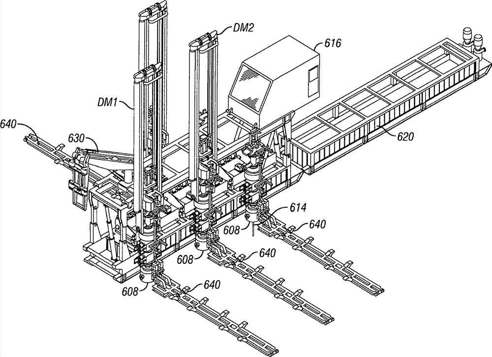
图15显示了根据本发明的系统600,其包括具有钻台604的可竖立的钻机结构602,多个具有泥浆池606p的振动筛606(参见例如图15A)位于钻台604下面,可任选地,如图15A中所示,具有用于将材料移入或移出泥浆池606p的螺旋钻设备606a。振动筛和泥浆池设置在井筒位置611-614之间,并且可根据需要移入该位置或从该位置移出。对于每一个井位置,可具有压力控制设备(例如流管路;防喷设备;和/或分流器设备-由数字608标示)。如图所示,多个防喷器组608每一个设置在井筒位置611-614上方。在一些特定方面,在位置611-614处待钻出的井至少间隔开8英尺,并且最大间隔开25英尺,但是任何所需间距都在本发明的范围内。在一个特定方面,井间隔开大约15英尺。振动筛设备606由结构602支撑。Figure 15 shows a
多种机器可与系统600一起使用,包括但不限于图3-20A的任何系统中的任何机器。在一个方面,两个钻井机DM1和DM2连接到钻机结构602或与钻机结构602邻近,并且起下钻机TM1连接到钻机结构602或与钻机结构602邻近。任何机器可移动到任何井位置上方的位置。可任选地,并且根据选择,所述机器可由压力控制设备和/或由围绕任何这样的设备的框架(例如,图15中所示的框架608f,其部分包围井口608w)支撑。在这样的情况下,钻井载荷(钻井机和/或连接到钻井机的管状钻柱和/或连接到管状钻柱的设备的载荷)由压力控制设备(例如但不限于由防喷器组和/或围绕其的框架)支撑。可任选地,例如,如图17N中所示,机器由设备608支撑,并且如果其在结构602上移动,则不遮挡司钻房616。A variety of machines may be used with
司钻房616连接到钻机结构602,并且另一个司钻房618(或司钻房616的延伸部)连接到位于在用钻机泥浆系统620(其可包括泥浆池结构)上方的竖立结构622。竖立结构622包括位置锁定设备621和动力竖立设备623,624(例如但不限于,动力缸设备、丝杠设备和/或发动机驱动设备)。可任选地,司钻房616可从该结构一端移动到另一端。A driller's
如图15B中所示,司钻房616已经放置在钻机结构602的钻台604上,并且连接到钻机结构602的钻台604。如图15C中所示,起重机630已经放置在钻台604的轨道604r上,并且连接到钻台604的轨道604r。在底座630b上的起重机630具有滚轮设备632,其在轨道604r上移动。图15D示出在用钻机泥浆系统620的位置和其连接到钻机结构602(钻机结构602完全竖立)的情况。As shown in FIG. 15B , driller's
图16A-16C示出了钻机结构602竖立过程中的步骤。动力缸设备624连接在钻机结构602的顶部602a和底部602b之间。如图16A中所示,为设备624供给能量,并且钻机结构602开始升高。如图16B中所示,钻机结构602继续升高。如图16C中所示,钻机结构602已经达到其全高,并且使用锁定设备625锁定就位。16A-16C illustrate steps in the erection process of the
钻机结构602具有四个多部件腿605,其每一个具有底座605a、可枢转连接的中间部分605b和上部605c。The
图17A-17S示出了根据本发明的使用系统600的方法中的步骤。17A-17S illustrate steps in a method of using
如图17A中所示,防喷器组608由升高设备升高,例如由起重机630升高,并且在井位置613上方放置就位。As shown in FIG. 17A ,
钻井机DM1移动到与钻机结构602的一端邻近,并且起重机630前进来开始升高钻井机DM1(图17B)。图17C显示了升高钻井机DM1的起重机630,图17D示出了将钻井机DM1在钻机结构602的端部处保持竖直的起重机630。Drilling machine DM1 is moved adjacent to one end of
图17E显示了在钻台604的轨道604r中移动同时支撑钻井机DM1的起重机620。图17F显示了处于防喷器组608上方的位置中的钻井机DM1,同时钻井机DM1仍连接到起重机630。Figure 17E shows the
图17G示出钻杆竖立器设备640,其具有用于起下钻操作的管,该设备已经移到与井位置613邻近,以例如供给钻杆来由钻井机DM1进行钻井,或供给管状件例如套管来用于起下钻操作。Figure 17G shows a drill
如图17H中所示,起重机630已经将另一个防喷器组在井位置614上方放置就位。起重机630连接到并且升高第二钻井机DM2(图17I),并且将其在井位置614上方移动就位(图17J)。同时,钻井机DM1在井位置613处钻井筒(图17I-17K)。As shown in FIG. 17H , the
如图17K中所示,管竖立器设备640已经与井位置614邻近设置,以提供钻杆,用于由钻井机DM2钻井,并且起重机630已经移动到钻台604的与具有司钻房616的端部相对的端部。As shown in FIG. 17K ,
在钻井利用钻井机DM1和DM2开始的同时,起重机630已经将另一个防喷器组608设置在井位置611上方(图17L),并且另一个管竖立器设备640已经与井位置611邻近设置。While drilling begins with rigs DM1 and DM2 ,
在已经在井位置613处钻出井筒之后,钻井机DM1由起重机630移到在井位置611处的防喷器组608上方(图17M),同时使用钻井机DM2继续进行钻井。After the wellbore has been drilled at
如图17N中所示,起重机630已经将起下钻机TM1在井位置613处移动就位,并且起下钻机已经开始起下钻操作,例如用于起出钻杆,和或下入套管来将套管下入井位置613处的井筒,并且使用钻井机DM1(井位置611)和使用钻井机DM2(井位置614)进行钻井。As shown in Figure 17N,
起重机630将防喷器组608(或如果使用的其它压力控制设备)在井位置612处移动就位,并且将管竖立器设备640设置在该井位置处(图17O)。同时,钻井机DM1、DM2和TM1继续其操作。The
图17P示出在起重机630已经将起下钻机移动到井位置614之后,钻井机DM2由起重机630移向井位置612。同时,钻井机DM1和起下钻机TM1一样继续操作,固井机CM1(之前由起重机移动就位)将套管使用水泥在井筒613中固定就位。FIG. 17P shows drilling rig DM2 being moved by
如图17Q中所示,钻井机DM2已经开始在井位置612处钻井筒,同时机器DM1、CM1和TM1继续操作。As shown in Figure 17Q, drilling machine DM2 has begun drilling the wellbore at
图17R显示了在井位置611处进行起下钻操作的起下钻机TM1(在由起重机630移动之后),同时钻井机DM2继续在井位置612处钻井筒。同时,起重机630将钻井机DM1移动到新的井位置615(在将防喷器组608移动到那里之后,并且在将钻杆竖立器设备640已经安装在那里之后)。在被移动到井位置614之后,固井机CM1在井筒614中将套管注水泥固定。FIG. 17R shows drilling rig TM1 performing a tripping operation at well location 611 (after being moved by crane 630 ), while drilling rig DM2 continues to drill the wellbore at
如图17S中所示,钻井机DM1已经开始在井位置615处钻井筒;钻井机DM2正在井位置612处完成钻井操作;并且固井机CM1正在完成对井筒614进行的注水泥固井工作。As shown in FIG. 17S , drilling machine DM1 has begun drilling the wellbore at
可任选地,在图17A-17S中的任何井位置处,根据需要使用固井机。此时钻出井位置611和613处的井筒,并且下入套管。Optionally, at any of the well locations in Figures 17A-17S, a cementing machine is used as needed. The wellbore at
图18显示了根据本发明的具有钻机结构702(类似于钻机结构602)和司钻房716(类似于司钻房616)的系统700。司钻房716安装在底座720上,底座720可在钻机结构702的钻台704上移动。底座720具有多个滚轮设备722(具有四个,每一侧两个,显示了两个),以便于底座720在钻台704上移动。FIG. 18 shows a
本文公开的根据本发明的任何系统可具有可移动的司钻房(例如,类似于系统700的司钻房)。Any of the systems disclosed herein according to the invention may have a movable driller's cabin (eg, a driller's cabin similar to system 700 ).
图19示出根据本发明的系统730,其具有钻机结构732(类似于钻机结构602或702),钻机结构732具有钻台734,可任选地,一系列振动筛736位于钻台734下面。两个起重机731、733可移动地安装在钻台734上。每一个起重机具有底座735和滚轮设备738。Figure 19 shows a
系统730可具有如本文公开的任何系统中的司钻房(例如但不限于图15A和18的系统),或其可具有与钻机结构732间隔开但是设置用于查看整个钻机结构732和利用其进行的操作的司钻房739(根据本发明的任何系统可使用司钻房739代替上面公开的用于任何这样的系统的司钻房)。
本文公开的根据本发明的任何系统可具有多个可移动的起重机(例如类似于系统730)。Any system according to the invention disclosed herein may have multiple movable cranes (eg, similar to system 730).
图20A-20C公开了根据本发明的系统750,其具有钻机结构752,该钻机结构752具有钻台754和可任选的顶部756。系统750可如本文上面描述的系统一样完全封闭。多个井操作机器可移动地安装在该钻机结构752上,所述机器包括针对上述的根据本发明的任何系统所描述的任何一个或多个机器。如图20C中所示,系统750具有钻井机760、起下钻机762和固井机764。上部结构758支撑可移动起重机770,可移动起重机770可移动以将所述机器中的任何机器移动到所需位置。系统750设置在多个井位置上方,一个井位置对应于如20C中所示的六个机器中的每一个。司钻房772类似于上面描述的任何司钻房;并且在一个方面,在机器移走不挡道的情况下,可沿钻台754移动。20A-20C disclose a system 750 according to the present invention having a rig structure 752 with a
本发明因此提供了多功能钻机,其用于由多功能钻机生产多个间隔开的井筒,所述多功能钻机在某些方面包括:底座,所述底座位于多个井筒位置上方;多个机器,其位于底座上;所述多个机器中的每一个机器用于完成与生产井筒相关的任务;每一个机器可在底座上相对于底座移动到与多个井筒位置邻近的位置,以在该处进行操作,从而使得可生产多个井筒而无需将钻机从井筒位置移动到另一个井筒位置;和移动设备,其可移动地安装在底座上,用于将机器相对于底座移动。这样的钻机可以任何可能组合具有下面的一个或一些特征:多个机器包括多个钻井机和至少一个起下钻机和/或至少一个固井机和/或至少一个辅助钻井机,辅助钻井机用于钻出井筒的导管部分;多个机器包括至少一个加热器安装机;多个机器包括至少一个套管钻井机;多个机器包括至少一个下套管机;多个机器包括至少一个固井机;多个机器包括至少一个管架设备,所述至少一个管架设备设置在所述多个机器中的一个机器的后面(而非在机器和井位置之间);司钻房,人可从该司钻房察看到操作中的多个机器中的所有机器;其中,司钻房可在底座上移动,以察看钻机和/或操作中的多个机器;其中,底座通常是矩形的或不是矩形的;其中,生产的井筒中的每一个是下入有套管的、注水泥固井的井筒;压力控制设备可操作地设置在每一个井筒位置处;其中,压力控制设备为流管路设备、防喷器设备和分流器中的一种;其中,压力控制设备支撑钻井载荷(例如,由防喷器设备、围绕其的框架和/或井口支撑载荷);其中,多个机器能够同时在至少两个井位置处进行多个操作;管架设备,其为具有基本竖直取向的管状件的管架或具有基本非竖直取向的管状件的管架;辅助钻井设备,其用于钻出井筒的上部分;控制系统设备,其用于选择地控制多个机器;和/或其中,所述控制系统设备控制所述多个机器以自动操作来执行其功能;和/或筛设备和一个或多个泥浆池,其在所述钻机结构内,并且可选择地从其移出,并且在一个方面,筛设备和一个或多个泥浆池可独立于任何压力控制设备和/在每一个井位置处的BOP而从底座移动离开。The present invention thus provides a multifunctional drilling rig for producing a plurality of spaced apart wellbores from a multifunctional drilling rig comprising in certain aspects: a base positioned over a plurality of wellbore locations; a plurality of machine , which is located on a base; each of the plurality of machines is configured to perform a task associated with a production wellbore; each machine is movable on the base relative to the base to a position adjacent to a plurality of wellbore locations for use in the operating at one location so that multiple wellbores can be produced without moving the drilling rig from one wellbore location to another; and a mobile device movably mounted on the base for moving the machine relative to the base. Such a drilling machine may have one or some of the following features in any possible combination: a plurality of machines including a plurality of drilling machines and at least one tripping machine and/or at least one cementing machine and/or at least one auxiliary drilling machine, the auxiliary drilling machine is used The plurality of machines includes at least one heater installation machine; the plurality of machines includes at least one casing drilling machine; the plurality of machines includes at least one casing running machine; the plurality of machines includes at least one cementing machine the plurality of machines includes at least one pipe racking device disposed behind one of the plurality of machines (rather than between the machine and the well location); the driller's cabin, accessible from The driller's cab has visibility to all of the machines in operation; wherein the cab is movable on the base to view the drill rig and/or the machines in operation; wherein the base is typically rectangular or not Rectangular; wherein each of the producing wellbores is a cased, cemented wellbore; a pressure control device is operably disposed at each wellbore location; wherein the pressure control device is a flow line equipment, blowout preventer equipment, and diverters; where the pressure control equipment supports the drilling load (e.g., by the blowout preventer equipment, the frame surrounding it, and/or the wellhead); where multiple machines can simultaneously Multiple operations are performed at at least two well locations; pipe racking equipment, which is a pipe rack with substantially vertically oriented tubulars or a pipe rack with substantially non-vertical oriented tubulars; auxiliary drilling equipment for Drilling the upper portion of the wellbore; a control system device for selectively controlling a plurality of machines; and/or wherein the control system device controls the plurality of machines to operate automatically to perform their functions; and/or a screen device and one or more mud pits within, and optionally removable from, the rig structure, and in one aspect, the screen apparatus and one or more mud pits may be independent of any pressure control apparatus and/on each The BOP at the well location is moved away from the base.
因此,综上所述,可以看出,本文公开的本发明和实施例以及由所附权利要求覆盖的本发明和实施例非常适于实现提出的目标并且获得提出的结果。可对主题进行一些改变而不偏离本发明的精神和范围。应意识到,在本发明的范围内进行改变是可能的,并且还希望,在下面的权利要求的任一个中述及的每一个元件或步骤应理解为是指该元件或步骤的字面意义和/或所有等同元件或步骤。下面的权利要求旨在在法律上尽可能宽地涵盖本发明,包括其可能应用的任何形式。From the foregoing, therefore, it can be seen that the invention and the embodiments disclosed herein, as well as the invention and the embodiments covered by the appended claims, are well adapted to carry out the objects set forth and to obtain the results set forth. Several changes may be made to the subject matter without departing from the spirit and scope of the invention. It will be appreciated that changes are possible within the scope of the invention, and it is also intended that each element or step recited in any one of the following claims be understood to refer to that element or step literally and /or all equivalent elements or steps. The following claims are intended to cover the invention as broadly as legally possible, in any form in which it may be applied.
Claims (72)
Applications Claiming Priority (5)
| Application Number | Priority Date | Filing Date | Title |
|---|---|---|---|
| US18914608P | 2008-08-15 | 2008-08-15 | |
| US61/189,146 | 2008-08-15 | ||
| US12/316,801 US8181697B2 (en) | 2008-08-15 | 2008-12-15 | Multi-function multi-hole drilling rig |
| US12/316,801 | 2008-12-15 | ||
| PCT/US2009/053849 WO2010019858A1 (en) | 2008-08-15 | 2009-08-14 | Multi-function multi-hole drilling rig |
Publications (2)
| Publication Number | Publication Date |
|---|---|
| CN102137982A CN102137982A (en) | 2011-07-27 |
| CN102137982B true CN102137982B (en) | 2014-01-22 |
Family
ID=41259796
Family Applications (1)
| Application Number | Title | Priority Date | Filing Date |
|---|---|---|---|
| CN200980131645.6A Expired - Fee Related CN102137982B (en) | 2008-08-15 | 2009-08-14 | Multifunctional drilling rig and method of performing drilling rig operations |
Country Status (7)
| Country | Link |
|---|---|
| US (1) | US8181697B2 (en) |
| EP (1) | EP2324186B1 (en) |
| CN (1) | CN102137982B (en) |
| BR (1) | BRPI0917536B1 (en) |
| CA (1) | CA2731107C (en) |
| RU (1) | RU2507366C2 (en) |
| WO (1) | WO2010019858A1 (en) |
Families Citing this family (41)
| Publication number | Priority date | Publication date | Assignee | Title |
|---|---|---|---|---|
| US8720565B2 (en) | 2006-04-25 | 2014-05-13 | National Oilwell Varco, L.P. | Tubular severing system and method of using same |
| US8424607B2 (en) * | 2006-04-25 | 2013-04-23 | National Oilwell Varco, L.P. | System and method for severing a tubular |
| US7367396B2 (en) | 2006-04-25 | 2008-05-06 | Varco I/P, Inc. | Blowout preventers and methods of use |
| US8720564B2 (en) | 2006-04-25 | 2014-05-13 | National Oilwell Varco, L.P. | Tubular severing system and method of using same |
| US8555974B2 (en) * | 2008-03-06 | 2013-10-15 | Devin International, Inc. | Coiled tubing well intervention system and method |
| US20120043136A1 (en) * | 2008-08-15 | 2012-02-23 | Dirk Alfermann | Drilling rig for deep well drilling |
| US8181697B2 (en) | 2008-08-15 | 2012-05-22 | National Oilwell Varco L.P. | Multi-function multi-hole drilling rig |
| US8181698B2 (en) * | 2008-08-15 | 2012-05-22 | National Oilwell Varco L.P. | Multi-function multi-hole drilling rig |
| US8844898B2 (en) | 2009-03-31 | 2014-09-30 | National Oilwell Varco, L.P. | Blowout preventer with ram socketing |
| US8511020B2 (en) * | 2009-08-18 | 2013-08-20 | Crux Subsurface, Inc. | Composite cap |
| US8544538B2 (en) | 2010-07-19 | 2013-10-01 | National Oilwell Varco, L.P. | System and method for sealing a wellbore |
| US8540017B2 (en) | 2010-07-19 | 2013-09-24 | National Oilwell Varco, L.P. | Method and system for sealing a wellbore |
| US8733472B2 (en) * | 2010-09-13 | 2014-05-27 | Christopher Magnuson | Multi-operational multi-drilling system |
| US8807219B2 (en) | 2010-09-29 | 2014-08-19 | National Oilwell Varco, L.P. | Blowout preventer blade assembly and method of using same |
| US8672043B2 (en) | 2010-11-03 | 2014-03-18 | Nabors Alaska Drilling, Inc. | Enclosed coiled tubing boat and methods |
| SG193346A1 (en) | 2011-03-09 | 2013-10-30 | Nat Oilwell Varco Lp | Method and apparatus for sealing a wellbore |
| AU2012242798B2 (en) * | 2011-04-14 | 2015-12-17 | Shell Internationale Research Maatschappij B.V. | Self-propelled simultaneous platform |
| WO2012165954A2 (en) * | 2011-05-27 | 2012-12-06 | Itrec B.V. | Land based earth boring system |
| US9091126B2 (en) | 2012-04-17 | 2015-07-28 | National Oilwell Varco, L.P. | Mobile drilling rig with telescoping substructure boxes |
| US9382766B2 (en) * | 2012-06-21 | 2016-07-05 | Superior Energy Services-North America Services, Inc. | Method and apparatus for working multiple wellheads in close proximity |
| US9926719B2 (en) | 2013-02-13 | 2018-03-27 | Nabors Drilling Technologies Usa, Inc. | Slingshot side saddle substructure |
| WO2014130703A2 (en) | 2013-02-21 | 2014-08-28 | National Oilwell Varco, L.P. | Blowout preventer monitoring system and method of using same |
| US9725970B1 (en) | 2013-09-18 | 2017-08-08 | CRW Contracting, Inc. | Compact pipe handling trailer |
| US9464488B2 (en) | 2013-09-30 | 2016-10-11 | National Oilwell Varco, L.P. | Performing simultaneous operations on multiple wellbore locations using a single mobile drilling rig |
| US9518429B2 (en) * | 2013-10-31 | 2016-12-13 | Independence Contract Drilling, Inc. | Walking drilling rig |
| CN105814855B (en) | 2013-12-09 | 2020-04-21 | 瑞典爱立信有限公司 | Precoding in Super Nyquist Transmission System |
| CN105849358B (en) * | 2013-12-26 | 2017-12-22 | 赛瓦集团有限责任公司 | The method of coil pipe derrick and maintenance well |
| US10323502B2 (en) * | 2014-05-02 | 2019-06-18 | Kongsberg Oil And Gas Technologies As | System and console for monitoring and managing tripping operations at a well site |
| GB2531781A (en) * | 2014-10-30 | 2016-05-04 | Nat Oilwell Varco Norway As | Rig floor for a drilling rig |
| US10323473B2 (en) * | 2014-12-10 | 2019-06-18 | Nabors Industries, Inc. | Modular racker system for a drilling rig |
| US9677345B2 (en) | 2015-05-27 | 2017-06-13 | National Oilwell Varco, L.P. | Well intervention apparatus and method |
| US9828739B2 (en) | 2015-11-04 | 2017-11-28 | Crux Subsurface, Inc. | In-line battered composite foundations |
| NO340840B1 (en) * | 2015-12-18 | 2017-06-26 | Odfjell Drilling As | Method and a system for performing several well activities. |
| EP3260648B1 (en) | 2016-06-24 | 2023-03-08 | Grant Prideco, Inc. | Jack-up rig for performing multiple independent operations simultaneously |
| US11035178B2 (en) * | 2018-07-13 | 2021-06-15 | James C. Evans | Apparatus and methods for moving workover rigs |
| US10837238B2 (en) * | 2018-07-19 | 2020-11-17 | Nabors Drilling Technologies Usa, Inc. | Side saddle slingshot continuous motion rig |
| US11280137B2 (en) * | 2019-06-17 | 2022-03-22 | Nabors Drilling Technologies Usa, Inc. | Dual mast rig with independently adjustable platforms |
| WO2021037361A1 (en) * | 2019-08-28 | 2021-03-04 | Rigtec As | Arrangement for drilling system, drilling system and method |
| NL2024028B1 (en) | 2019-10-16 | 2021-06-17 | Itrec Bv | Land rig comprising auxiliary tower |
| CN115885084A (en) | 2020-09-01 | 2023-03-31 | 内搏斯铂井技术美国公司 | Side saddle traverse drilling rig |
| US12054993B2 (en) | 2021-03-16 | 2024-08-06 | Nabors Drilling Technologies Usa, Inc. | Side saddle rig design with retractable top drive |
Family Cites Families (47)
| Publication number | Priority date | Publication date | Assignee | Title |
|---|---|---|---|---|
| US932808A (en) | 1909-04-17 | 1909-08-31 | Henry B Pelton | Paper-roll protector. |
| US2840198A (en) | 1955-12-23 | 1958-06-24 | Moore Corp Lee C | Apparatus and method for multiple well drilling |
| SU135047A1 (en) * | 1958-06-04 | 1960-11-30 | Л.И. Берхман | Burov installation |
| US3486737A (en) | 1968-01-30 | 1969-12-30 | Moore Corp Lee C | Apparatus for skidding a load on a support |
| US4042123A (en) * | 1975-02-06 | 1977-08-16 | Sheldon Loren B | Automated pipe handling system |
| US4108255A (en) | 1975-05-29 | 1978-08-22 | Smith Craig R | Well drilling apparatus |
| SU655808A1 (en) * | 1976-03-09 | 1979-04-05 | Западно-Сибирский Филиал Всесоюзного Научно-Исследовательского И Проектно-Конструкторского Института Нефтяного Машиностроения | Drilling rig for grouping of wells |
| SU720131A1 (en) * | 1977-12-07 | 1980-03-05 | Всесоюзный Научно-Исследовательский И Проектно-Конструкторский Институт Нефтяного Машиностроения | Support of drilling rig for multiple drilling of wells |
| US4208158A (en) * | 1978-04-10 | 1980-06-17 | Franklin Enterprises, Inc. | Auxiliary offshore rig and methods for using same |
| SU870654A1 (en) * | 1979-11-14 | 1981-10-07 | Производственный И Научно-Исследовательский Институт По Инженерным Изысканиям В Строительстве Государственного Комитета Совета Министров Ссср По Делам Строительства | Device for sinkling holes |
| CA1232898A (en) | 1985-02-19 | 1988-02-16 | Leon V. Jankowski | Slant service rig |
| SU1247504A1 (en) * | 1985-02-26 | 1986-07-30 | Государственный Научно-Исследовательский И Проектный Институт По Освоению Месторождений Нефти И Газа | Stationary offshore platform for multiple drilling |
| US4899832A (en) | 1985-08-19 | 1990-02-13 | Bierscheid Jr Robert C | Modular well drilling apparatus and methods |
| US4744710A (en) | 1986-11-24 | 1988-05-17 | Parco Mast And Substructures | Drilling derrick with external pipe storage |
| US4819730A (en) * | 1987-07-24 | 1989-04-11 | Schlumberger Technology Corporation | Development drilling system |
| US5107940A (en) | 1990-12-14 | 1992-04-28 | Hydratech | Top drive torque restraint system |
| CN2093239U (en) * | 1991-03-25 | 1992-01-15 | 曾瑞明 | Combined portable rock-drilling gang drill |
| US5492436A (en) | 1994-04-14 | 1996-02-20 | Pool Company | Apparatus and method for moving rig structures |
| RU2081289C1 (en) * | 1995-06-30 | 1997-06-10 | Государственная академия нефти и газа им.И.М.Губкина | Underwater drilling rig and supporting platform for it |
| DE19524389C1 (en) * | 1995-07-04 | 1996-10-02 | Georg Koehler | Self-propelled vertical and horizontal drilling equipment |
| US6085851A (en) | 1996-05-03 | 2000-07-11 | Transocean Offshore Inc. | Multi-activity offshore exploration and/or development drill method and apparatus |
| NO304708B1 (en) | 1996-11-11 | 1999-02-01 | Gunnar Kristiansen | Device at drill tower |
| US6161358A (en) | 1998-07-28 | 2000-12-19 | Mochizuki; David A. | Modular mobile drilling system and method of use |
| US6158516A (en) | 1998-12-02 | 2000-12-12 | Cudd Pressure Control, Inc. | Combined drilling apparatus and method |
| US6203247B1 (en) * | 1998-12-10 | 2001-03-20 | Herman J. Schellstede | Drilling vessel with moveable substructure |
| US6443240B1 (en) | 1999-10-06 | 2002-09-03 | Transocean Sedco Forex, Inc. | Dual riser assembly, deep water drilling method and apparatus |
| RU2214962C2 (en) * | 2000-10-05 | 2003-10-27 | Сафонов Георгий Леонидович | Load handling crane |
| US6554075B2 (en) | 2000-12-15 | 2003-04-29 | Halliburton Energy Services, Inc. | CT drilling rig |
| CA2364147A1 (en) | 2001-11-28 | 2003-05-28 | Cancoil Integrated Services Inc. | Improved mast and trolley arrangement for mobile multi-function rig |
| US6766860B2 (en) | 2002-02-22 | 2004-07-27 | Globalsantafe Corporation | Multi-activity offshore drilling facility having a support for tubular string |
| US6745852B2 (en) * | 2002-05-08 | 2004-06-08 | Anadarko Petroleum Corporation | Platform for drilling oil and gas wells in arctic, inaccessible, or environmentally sensitive locations |
| US7083004B2 (en) | 2002-10-17 | 2006-08-01 | Itrec B.V. | Cantilevered multi purpose tower and method for installing drilling equipment |
| US6932553B1 (en) | 2003-03-17 | 2005-08-23 | Itrec, B.V. | Multipurpose unit for drilling and well intervention |
| US6968905B2 (en) * | 2003-03-18 | 2005-11-29 | Schlumberger Technology Corporation | Distributed control system |
| CA2425062A1 (en) | 2003-04-10 | 2004-10-10 | Robert D. Markle | Method and apparatus for movement of drilling equipment between adjacent locations |
| US6973979B2 (en) | 2003-04-15 | 2005-12-13 | Savanna Energy Services Corp. | Drilling rig apparatus and downhole tool assembly system and method |
| RU2262583C2 (en) * | 2003-07-21 | 2005-10-20 | Совместное закрытое акционерное общество "ФИДМАШ" | Mobile well repair plant |
| ATE430872T1 (en) | 2004-06-02 | 2009-05-15 | Stena Drilling Ltd | FACILITY FOR MULTIPLE ACTIVITIES |
| US7320374B2 (en) | 2004-06-07 | 2008-01-22 | Varco I/P, Inc. | Wellbore top drive systems |
| RU2274728C1 (en) * | 2004-11-18 | 2006-04-20 | Сибирское научно-производственное предприятие бурового машиностроения (ЗАО НПП "СибБурМаш") | Well head sealing device |
| NO323508B1 (en) * | 2005-07-05 | 2007-05-29 | Seabed Rig As | Drilling rig located on the seabed and equipped for drilling of oil and gas wells |
| US7401656B2 (en) | 2005-12-05 | 2008-07-22 | Xtreme Coil Drilling Corp. | Mobile drilling rig with dual carriers |
| US7431105B2 (en) | 2006-07-25 | 2008-10-07 | Stevens Joseph W | Geothermal heat loop installation |
| US7802636B2 (en) | 2007-02-23 | 2010-09-28 | Atwood Oceanics, Inc. | Simultaneous tubular handling system and method |
| WO2008118914A1 (en) | 2007-03-26 | 2008-10-02 | Technip France | Parallel drilling and completion for a dry tree floating production facility |
| US9062500B2 (en) | 2007-07-20 | 2015-06-23 | Schlumberger Technology Corporation | System and method to facilitate interventions from an offshore platform |
| US8181697B2 (en) | 2008-08-15 | 2012-05-22 | National Oilwell Varco L.P. | Multi-function multi-hole drilling rig |
-
2008
- 2008-12-15 US US12/316,801 patent/US8181697B2/en active Active
-
2009
- 2009-08-14 CA CA2731107A patent/CA2731107C/en active Active
- 2009-08-14 BR BRPI0917536-9A patent/BRPI0917536B1/en active IP Right Grant
- 2009-08-14 CN CN200980131645.6A patent/CN102137982B/en not_active Expired - Fee Related
- 2009-08-14 WO PCT/US2009/053849 patent/WO2010019858A1/en not_active Ceased
- 2009-08-14 RU RU2011109458/03A patent/RU2507366C2/en active
- 2009-08-14 EP EP09791527.6A patent/EP2324186B1/en active Active
Also Published As
| Publication number | Publication date |
|---|---|
| EP2324186A1 (en) | 2011-05-25 |
| CA2731107C (en) | 2016-09-13 |
| CA2731107A1 (en) | 2010-02-18 |
| BRPI0917536B1 (en) | 2020-10-06 |
| EP2324186B1 (en) | 2016-05-04 |
| RU2507366C2 (en) | 2014-02-20 |
| BRPI0917536A2 (en) | 2019-10-15 |
| RU2011109458A (en) | 2012-09-20 |
| CN102137982A (en) | 2011-07-27 |
| US8181697B2 (en) | 2012-05-22 |
| WO2010019858A1 (en) | 2010-02-18 |
| US20100038088A1 (en) | 2010-02-18 |
Similar Documents
| Publication | Publication Date | Title |
|---|---|---|
| CA2731107C (en) | Multi-function multi-hole drilling rig | |
| CA2783675C (en) | Multi-function multi-hole drilling rig | |
| US10094136B2 (en) | Drilling rig system with self-elevating drill floor | |
| US5842530A (en) | Hybrid coiled tubing/conventional drilling unit | |
| CA2781076C (en) | A method and system for facilitating assembly of a drilling rig | |
| CA2824963C (en) | Method and apparatus for drilling auxiliary holes | |
| CN103119239B (en) | Multi-operable multi-drilling system | |
| US7527100B2 (en) | Method and apparatus for cutting and removal of pipe from wells | |
| EP2578794B1 (en) | Mast for drilling rigs and method of assembling the same | |
| EA015157B1 (en) | System for conducting jointed pipe and coiled tubing operations | |
| CN109424324A (en) | Drilling machine high capacity derrick | |
| Young | UTB: Rig layout and rig operation for ultradeep scientific drilling |
Legal Events
| Date | Code | Title | Description |
|---|---|---|---|
| C06 | Publication | ||
| PB01 | Publication | ||
| C10 | Entry into substantive examination | ||
| SE01 | Entry into force of request for substantive examination | ||
| C14 | Grant of patent or utility model | ||
| GR01 | Patent grant | ||
| CF01 | Termination of patent right due to non-payment of annual fee |
Granted publication date: 20140122 Termination date: 20210814 |
|
| CF01 | Termination of patent right due to non-payment of annual fee |