CN102111990B - Light-emitting diode (LED) plugin device - Google Patents
Light-emitting diode (LED) plugin device Download PDFInfo
- Publication number
- CN102111990B CN102111990B CN 201110030421 CN201110030421A CN102111990B CN 102111990 B CN102111990 B CN 102111990B CN 201110030421 CN201110030421 CN 201110030421 CN 201110030421 A CN201110030421 A CN 201110030421A CN 102111990 B CN102111990 B CN 102111990B
- Authority
- CN
- China
- Prior art keywords
- cylinder
- led
- workbench
- slide
- plate
- Prior art date
- Legal status (The legal status is an assumption and is not a legal conclusion. Google has not performed a legal analysis and makes no representation as to the accuracy of the status listed.)
- Expired - Fee Related
Links
Images


Landscapes
- Automatic Assembly (AREA)
Abstract
Description
技术领域 technical field
本发明涉及电子元件装配技术领域,尤其是一种LED插件装置。 The invention relates to the technical field of electronic component assembly, in particular to an LED plug-in device.
背景技术 Background technique
随着科学技术的发展,我国各项产业机械设备也已逐步走向自动化。目前市面上的插件机主要采用真空吸嘴拾取电子元件,这种插件机结构往往都很复杂,其维护成本较高,对企业造成较大的资金压力,而且这种插件机是专用插件机,其适用范围较窄,目前还没有LED专用插件机。另外,这些插件机对异形电子元件的插接力度往往难以控制,导致成品率的降低,造成浪费。目前,市面还没有维护成本低、适用范围大、自动插接精准、成品率较高的LED插件装置。 With the development of science and technology, various industrial machinery and equipment in our country have gradually moved towards automation. At present, the plug-in machines on the market mainly use vacuum nozzles to pick up electronic components. The structure of this plug-in machine is often very complicated, and its maintenance cost is high, which causes great financial pressure on the company. Moreover, this plug-in machine is a special plug-in machine. Its scope of application is relatively narrow, and there is no special plug-in machine for LEDs at present. In addition, these plug-in machines are often difficult to control the insertion force of special-shaped electronic components, resulting in a reduction in yield and waste. At present, there is no LED plug-in device with low maintenance cost, wide application range, accurate automatic plugging and high yield rate in the market.
发明内容 Contents of the invention
本发明要解决上述现有技术的缺点,提供一种维护成本低、适用范围大、自动插接精准、成品率较高的LED插件装置,满足生产需求。 The present invention aims to solve the above-mentioned shortcomings of the prior art, and provides an LED plug-in device with low maintenance cost, wide application range, precise automatic insertion and high yield rate, so as to meet production requirements.
本发明解决其技术问题采用的技术方案:这种LED插件装置,包括工作台,工作台上设有底板,底板两端均设有支撑板,两支撑板之间上横向设有滑轨、第一汽缸,滑轨上设有滑板,第一汽缸的活塞杆与滑板连接,滑板上设有第二汽缸,第二汽缸的活塞杆上设有安装板,安装板上设有拾取夹紧机构,拾取夹紧机构下方的工作台上设有具有X、Y方向进给功能的进给机构。工作台下设有控制器,第一汽缸、第二汽缸、拾取夹紧机构、进给机构均与控制器连接。这样,控制器发出指令,拾取夹紧机构将发光二极管夹紧拾取,第二汽缸的活塞杆收缩将拾取夹紧机构提起,接着启动第一汽缸和进给机构,调整合适的位置,第二汽缸的活塞杆伸展插接发光二极管,完成一次插件流程。 The technical solution adopted by the present invention to solve its technical problems: this LED plug-in device includes a workbench, a base plate is provided on the workbench, support plates are provided at both ends of the base plate, and slide rails are arranged horizontally between the two support plates. One cylinder, the slide rail is provided with a slide plate, the piston rod of the first cylinder is connected with the slide plate, the slide plate is provided with the second cylinder, the piston rod of the second cylinder is provided with a mounting plate, and the mounting plate is provided with a pick-up and clamping mechanism, The workbench below the pick-up and clamping mechanism is provided with a feed mechanism with X and Y direction feed functions. A controller is arranged under the workbench, and the first cylinder, the second cylinder, the picking and clamping mechanism, and the feeding mechanism are all connected with the controller. In this way, the controller issues an instruction, the pick-up and clamping mechanism clamps the light-emitting diode to pick up, the piston rod of the second cylinder shrinks to lift the pick-up and clamping mechanism, and then starts the first cylinder and the feed mechanism to adjust the appropriate position, the second cylinder The piston rod is stretched and inserted into the light-emitting diode to complete a plug-in process.
进一步,拾取夹紧机构包括设在安装板上的固定杆,固定杆上轴接有夹钳,夹钳的两腿内侧均设有弹性连杆,两弹性连杆通过圆柱销连接,圆柱销下方设有电磁铁,该电磁铁内设有衔铁,圆柱销固定在衔铁上。该弹性连杆为弹簧型连杆。这样,当需要拾取夹紧LED的时候,电磁铁通电,衔铁在电磁铁内往下移动,带动圆柱销,带动弹性连杆迫使夹钳做夹紧动作,弹性连杆可以起到缓冲的作用,避免夹紧时损坏LED。滑板上设有第三汽缸,第二汽缸设在第三汽缸的活塞杆上。这样可以延长拾取夹紧机构上下移动的距离,方便操作。滑板为L型滑板,滑板背面四角分别设有滑块,滑块套设在滑轨上。 Further, the pick-up and clamping mechanism includes a fixed rod arranged on the mounting plate. A clamp is connected to the shaft of the fixed rod. Elastic connecting rods are arranged on the inner sides of the two legs of the clamp. The two elastic connecting rods are connected by cylindrical pins. An electromagnet is provided, and an armature is arranged in the electromagnet, and a cylindrical pin is fixed on the armature. The elastic connecting rod is a spring-type connecting rod. In this way, when the LED needs to be picked up and clamped, the electromagnet is energized, and the armature moves down in the electromagnet, driving the cylindrical pin, driving the elastic connecting rod to force the clamp to perform clamping action, and the elastic connecting rod can play a buffering role. Avoid damaging the LED when clamping. A third cylinder is arranged on the slide plate, and the second cylinder is arranged on the piston rod of the third cylinder. This can prolong the distance that the pick-up and clamping mechanism moves up and down, which is convenient for operation. The skateboard is an L-shaped skateboard, the four corners of the back of the skateboard are respectively provided with sliders, and the sliders are sheathed on the slide rails.
本发明有益的效果是:本发明的结构合理、紧凑,通过夹钳、弹性连杆、圆柱销、、衔铁、电磁铁、进给机构及各汽缸的联动作用,实现发光二极管的精确拾取、插接装配过程,有效提高生产成品率,而且本发明中的各部件都是较为常见的零件,成本相对较低,维护也较为简单,并且适用于除LED外大多电子元件的插接。本发明成本较低,操作简单,实用方便,适合推广应用。 The beneficial effects of the present invention are: the structure of the present invention is reasonable and compact, and through the joint action of clamps, elastic connecting rods, cylindrical pins, armatures, electromagnets, feed mechanisms and cylinders, the precise pick-up and insertion of light-emitting diodes can be realized. The connection and assembly process can effectively improve the production yield, and each component in the present invention is a relatively common part, the cost is relatively low, and the maintenance is relatively simple, and it is suitable for the insertion of most electronic components except LEDs. The invention has the advantages of low cost, simple operation, practicality and convenience, and is suitable for popularization and application.
附图说明 Description of drawings
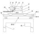
图1为本发明的结构示意图; Fig. 1 is a structural representation of the present invention;
图2为本发明中拾取夹紧机构及各汽缸的结构分布示意图; Fig. 2 is a schematic diagram of the structural distribution of the pick-up and clamping mechanism and each cylinder in the present invention;
图3为本发明中拾取夹紧机构侧视时的结构示意图。 Fig. 3 is a schematic structural view of the pickup and clamping mechanism in side view according to the present invention.
附图标记说明:工作台1,底板2,支撑板3,滑轨4,第一汽缸5,滑板6,滑块6-1、第二汽缸7,安装板8,拾取夹紧机构9,固定杆9-1、夹钳9-2、弹性连杆9-3、圆柱销9-4、电磁铁9-5、衔铁9-6、进给机构10,驱动电机10-1,丝杠10-2,导轨10-3,第三汽缸11,控制器12,LED13、印刷板14。
Explanation of reference signs:
具体实施方式 Detailed ways
下面结合附图对本发明作进一步说明: The present invention will be further described below in conjunction with accompanying drawing:
参照附图:本实施例中的这种LED插件装置,包括工作台1,工作台1上底板2,底板2两端均设有支撑板3,两支撑板3之间上横向设有滑轨4、第一汽缸5,滑轨4上设有滑板6,第一汽缸5的活塞杆与滑板6连接,滑板6上设有第三汽缸11,第三汽缸11的活塞杆上设有第二汽缸7,第二汽缸7的活塞杆上设有安装板8,安装板8上设有拾取夹紧机构9,拾取夹紧机构9包括设在安装板8上的固定杆9-1,固定杆9-1上轴接有夹钳9-2,夹钳9-2的两腿内侧均设有弹性连杆9-3,两弹性连杆9-3通过圆柱销9-4连接,圆柱销9-4下方设有电磁铁9-5,该电磁铁9-5内设有衔铁9-6,圆柱销9-4一端固定在衔铁9-6上。该弹性连杆9-3为弹簧型连杆。拾取夹紧机构9下方的工作台上设有具有X、Y方向进给功能的进给机构10。进给机构上放置印刷板14。该进给机构10包括X向进给机构、Y向进给机构,X向进给机构、Y向进给机构分别由驱动电机10-1、丝杠10-2、导轨10-3组成,驱动电机10-1驱动丝杠10-2使进给机构10移动配合插件装置的插件。工作台1下设有控制器12,第一汽缸5、第二汽缸7、拾取夹紧机构9、进给机构10均与控制器12连接。
Referring to the accompanying drawings: the LED plug-in device in this embodiment includes a
控制器12可编多种动作程序,是本领域的常识,故不多做描述。两弹性连杆9-3可以铰接在圆柱销9-4上,亦可套接在圆柱销9-4上,方便夹钳9-2动作,以减少对LED的伤害。
The
使用时,在控制器12的指令下,第二汽缸7的活塞向下移动,拾取夹紧机构9等也随之向下移动,当移动到最下端时,LED13刚好在两夹钳9-2之间,这时电磁铁9-5通电,衔铁9-6向下吸合移动,带动弹性连杆9-3迫使夹钳9-2做夹紧动作,使其夹住LED,然后第二汽缸7向上提起,第一汽缸5缩回,滑板6沿着滑轨4向右移动,第二汽缸7、第三汽缸11的活塞杆均向下移动,将LED插入印刷板14对应的孔内,这时,电磁铁9-5断电,在电磁铁内部的弹簧复位作用下(电磁铁内部具有使衔铁复位的弹簧是电磁铁领域的常识,故不多做描述),衔铁9-6向上移动,迫使夹钳9-2张开,从而松开LED13,接着第二汽缸7、第三汽缸11的活塞杆向上移动,第一汽缸5的活塞杆伸展,推动滑板6向左复位,拾取夹紧机构9就回到原来的位置去做二次拾取、夹紧、插件动作,在LED13插件时候的同时,驱动电机10-1驱动丝杠10-2使放置在进给机构10上方的印刷板14移动配合插件装置的插件。
During use, under the instructions of the
本发明维护成本低,适用范围大,自动插接精准,插件成品率高,适合推广应用。 The invention has low maintenance cost, wide application range, precise automatic plugging and high plug-in yield, and is suitable for popularization and application.
虽然本发明已通过参考优选的实施例进行了图示和描述,但是,本专业普通技术人员应当了解,在权利要求书的范围内,可作形式和细节上的各种各样变化。 Although the invention has been shown and described with reference to preferred embodiments, it will be understood by those skilled in the art that various changes in form and details may be made within the scope of the claims.
Claims (4)
Priority Applications (1)
| Application Number | Priority Date | Filing Date | Title |
|---|---|---|---|
| CN 201110030421 CN102111990B (en) | 2011-01-28 | 2011-01-28 | Light-emitting diode (LED) plugin device |
Applications Claiming Priority (1)
| Application Number | Priority Date | Filing Date | Title |
|---|---|---|---|
| CN 201110030421 CN102111990B (en) | 2011-01-28 | 2011-01-28 | Light-emitting diode (LED) plugin device |
Publications (2)
| Publication Number | Publication Date |
|---|---|
| CN102111990A CN102111990A (en) | 2011-06-29 |
| CN102111990B true CN102111990B (en) | 2012-07-25 |
Family
ID=44175961
Family Applications (1)
| Application Number | Title | Priority Date | Filing Date |
|---|---|---|---|
| CN 201110030421 Expired - Fee Related CN102111990B (en) | 2011-01-28 | 2011-01-28 | Light-emitting diode (LED) plugin device |
Country Status (1)
| Country | Link |
|---|---|
| CN (1) | CN102111990B (en) |
Families Citing this family (3)
| Publication number | Priority date | Publication date | Assignee | Title |
|---|---|---|---|---|
| CN102510717B (en) * | 2011-11-16 | 2014-06-04 | 宁波市新泽谷机械有限公司 | LED inserter |
| CN103458670B (en) * | 2013-09-04 | 2015-12-23 | 吴江市博众精工科技有限公司 | A kind of collect separation, install and pressurize one electronic product parts mount mechanism |
| CN107127566A (en) * | 2017-06-29 | 2017-09-05 | 淄博丰雁电子元件有限公司 | A kind of insert pad machine |
Citations (3)
| Publication number | Priority date | Publication date | Assignee | Title |
|---|---|---|---|---|
| CN1237085A (en) * | 1998-05-25 | 1999-12-01 | 索尼公司 | Assembling device |
| CN201303467Y (en) * | 2008-12-03 | 2009-09-02 | 东莞市新泽谷机械有限公司 | Head mechanism of profiled component inserter |
| CN201573205U (en) * | 2010-01-12 | 2010-09-08 | 铜陵三佳科技股份有限公司 | Air claw manipulator |
Family Cites Families (1)
| Publication number | Priority date | Publication date | Assignee | Title |
|---|---|---|---|---|
| CN201985153U (en) * | 2011-01-28 | 2011-09-21 | 浙江机电职业技术学院 | Led plug-in device |
-
2011
- 2011-01-28 CN CN 201110030421 patent/CN102111990B/en not_active Expired - Fee Related
Patent Citations (3)
| Publication number | Priority date | Publication date | Assignee | Title |
|---|---|---|---|---|
| CN1237085A (en) * | 1998-05-25 | 1999-12-01 | 索尼公司 | Assembling device |
| CN201303467Y (en) * | 2008-12-03 | 2009-09-02 | 东莞市新泽谷机械有限公司 | Head mechanism of profiled component inserter |
| CN201573205U (en) * | 2010-01-12 | 2010-09-08 | 铜陵三佳科技股份有限公司 | Air claw manipulator |
Also Published As
| Publication number | Publication date |
|---|---|
| CN102111990A (en) | 2011-06-29 |
Similar Documents
| Publication | Publication Date | Title |
|---|---|---|
| CN104889729B (en) | LED kludge | |
| CN102371481B (en) | Automatic assembly machine of bottom shell of LED (light-emitting diode) module | |
| CN102118960B (en) | A plug-in machine for special-shaped components | |
| CN203649812U (en) | Led lamp automatic assembling device | |
| CN204657926U (en) | LED kludge | |
| CN106057524B (en) | The turntable unit of travel switch kludge | |
| CN103737275B (en) | Light-emitting diode (LED) lamp automatic assembly device | |
| CN105744754B (en) | A kind of parallel clamp-type large-sized electronic component patch inserts operation head and its patch insert method | |
| CN105914068B (en) | The contact feed mechanism of travel switch contact part kludge | |
| CN104444303A (en) | Feeding device of LED plugging machine | |
| CN106181540B (en) | Full-automatic CCD material loading machine | |
| CN105744755B (en) | A kind of medium-sized electronic component patch inserts operation head and its patch insert method | |
| CN205953008U (en) | Automatic plug -in components device based on float and get mechanism with pressing from both sides | |
| CN102111990A (en) | Light-emitting diode (LED) plugin device | |
| CN115072368A (en) | Sucking disc assembly for horizontal line plate loading and unloading machine | |
| CN103407634A (en) | Dustproof material feeding mechanism capable of automatically uncovering dustproof membranes | |
| CN206365162U (en) | One kind is clipping to tear pcb board high temperature gluing mechanism automatically | |
| CN201985153U (en) | Led plug-in device | |
| CN105931890B (en) | The rivet feeding decompressor of travel switch bottom kludge | |
| CN218878707U (en) | PCB board moves and carries mechanism | |
| CN204182530U (en) | A kind of assembling of magnetic holder automatically automatic double surface gluer | |
| CN204316946U (en) | A kind of upper plate mechanism of inserter | |
| CN209367304U (en) | A kind of workpiece fetching device | |
| CN203327481U (en) | A plug-in mechanism used in fully automatic plug-in equipment for three-color bulk components | |
| CN203428120U (en) | Dust preventing feeding mechanism automatically removing dustproof film |
Legal Events
| Date | Code | Title | Description |
|---|---|---|---|
| C06 | Publication | ||
| PB01 | Publication | ||
| C10 | Entry into substantive examination | ||
| SE01 | Entry into force of request for substantive examination | ||
| C14 | Grant of patent or utility model | ||
| GR01 | Patent grant | ||
| ASS | Succession or assignment of patent right |
Owner name: XINCHANG TONGSHUN ELECTRONIC CO., LTD. Free format text: FORMER OWNER: ZHEJIANG INSTITUTE OF MECHANICAL + ELECTRICAL ENGINEERING Effective date: 20141113 |
|
| C41 | Transfer of patent application or patent right or utility model | ||
| COR | Change of bibliographic data |
Free format text: CORRECT: ADDRESS; FROM: 310053 HANGZHOU, ZHEJIANG PROVINCE TO: 312500 SHAOXING, ZHEJIANG PROVINCE |
|
| TR01 | Transfer of patent right |
Effective date of registration: 20141113 Address after: 312500 village, Chengguan Town, Xinchang County, Zhejiang, Shaoxing Patentee after: Xinchang smooth Electron Co., Ltd. Address before: Hangzhou City, Zhejiang province Binjiang District 310053 shore road 528 Patentee before: Zhejiang Institute of Mechanical & Electrical Engineering |
|
| CF01 | Termination of patent right due to non-payment of annual fee |
Granted publication date: 20120725 Termination date: 20150128 |
|
| EXPY | Termination of patent right or utility model |