CN102102392B - Integrated initial rainwater draining well and method for draining rainwater - Google Patents
Integrated initial rainwater draining well and method for draining rainwater Download PDFInfo
- Publication number
- CN102102392B CN102102392B CN2010106039115A CN201010603911A CN102102392B CN 102102392 B CN102102392 B CN 102102392B CN 2010106039115 A CN2010106039115 A CN 2010106039115A CN 201010603911 A CN201010603911 A CN 201010603911A CN 102102392 B CN102102392 B CN 102102392B
- Authority
- CN
- China
- Prior art keywords
- rainwater
- pipe
- storage pond
- abandoned stream
- well
- Prior art date
- Legal status (The legal status is an assumption and is not a legal conclusion. Google has not performed a legal analysis and makes no representation as to the accuracy of the status listed.)
- Expired - Fee Related
Links
Images

Classifications
-
- Y—GENERAL TAGGING OF NEW TECHNOLOGICAL DEVELOPMENTS; GENERAL TAGGING OF CROSS-SECTIONAL TECHNOLOGIES SPANNING OVER SEVERAL SECTIONS OF THE IPC; TECHNICAL SUBJECTS COVERED BY FORMER USPC CROSS-REFERENCE ART COLLECTIONS [XRACs] AND DIGESTS
- Y02—TECHNOLOGIES OR APPLICATIONS FOR MITIGATION OR ADAPTATION AGAINST CLIMATE CHANGE
- Y02A—TECHNOLOGIES FOR ADAPTATION TO CLIMATE CHANGE
- Y02A20/00—Water conservation; Efficient water supply; Efficient water use
- Y02A20/108—Rainwater harvesting
Abstract
The invention provides an integrated initial rainwater draining well, which is a device capable of draining certain millimeters of initial rainwater on an appointed water catchment panel and separating out later clean rainwater so as to greatly enhance the quality of the recycled rainwater. The integrated initial rainwater drainage well consists of a buried rainwater inspection well and a storage pool; the rainwater inspection well is connected with a water inlet pipe and a water outlet pipe; a bevel board precipitation structure is arranged at the bottom of the storage pool; a drainage pipe is arranged at a position a certain distance from the pool bottom; a lower sink and a flow baffle plate are arranged between the rainwater inspection well and the storage pool; at the highest water level, short flow is formed between the water inlet pipe and the water outlet pipe, so the later rainwater passes through the rainwater inspection well and directly enters the water outlet pipe to be recycled; the initial rainwater is drained in the storage pool; and after the rainwater runoff stops, the rainwater in the storage pool is slowly drained from the drainage pipe and stopped at the effective lowest water level. The integrated initial rainwater draining well has the advantages that: the structure is simple, the well operates in an unmanned way, a power supply is saved, the well is easy to maintain, polluted rainwater can be collected effectively, the drainage pipe is hardly blocked, the blocked drainage pipe is easy to smooth after being blocked and the buried drainage pipe is buried so that the appearance of the environment is not influenced.
Description
Technical field
The invention belongs to environmental protection technology, rainwater reuse field, be specifically related to a kind of integrated preliminary-stage rainwater flow-discarding well and operation method.
Background technology
Look into newly by science and technology, at present domestic and international rare early-stage rainwater stream abandoning device separates research report, patent, the practical engineering application of early-stage rainwater, and present existing early-stage rainwater stream abandoning device design application surface is wideless, does not reach Non-energy-consumption, the difficult advantage of stopping up, need not the personal management.
Since early-stage rainwater to the pollutant drip washing on the catchment area, wash away and the conveying effect, so that just contain whole the most of pollutant of rainfall in the issue millimeter rainwater.Generally speaking, the precontamination substrate concentration that forms runoff in rainfall is the highest, and along with rainfall duration increases, the pollutant levels in the rainfall runoff reduce gradually, finally maintain a lower concentration range.Early-stage rainwater stream abandoning can be removed most of pollutant in the runoff, comprises tiny or dissolubility pollutant.
Existing early-stage rainwater stream abandoning device comprises following several: abandoned stream stormwater tank, suitching type or tubule abandoned stream well, cyclone separator, automatic turnover type be rain separator, flow type or rainfall regime rain early-stage split-flow device, infiltration abandoned stream well and jump weir formula rainwater shunting well just.
Abandoned stream stormwater tank, Initial Runoff amount flow into first the interior and storage of pond body of corresponding volume, begin to flow into the recovery rain water collecting system when reaching certain volume.The operation of this abandoned stream stormwater tank early-stage rainwater emptying mostly is valve control, needs manually-operated, and every rain all needs valve open emptying later.
Suitching type or tubule abandoned stream well are buried two pipes that connect downstream catch-basin and downstream bilge well simultaneously underground in rainwater inspection well, manual simplified gate valve is set for two pipes or Automatic slucie valve switches.This device needs to control the early-stage rainwater stream abandoning amount by by-pass valve control, needs manually-operated or needs power supply.
Cyclone separator, rainwater tangentially flow into the eddy flow screen cloth.The rainfall initial stage is when screen surface is dry. and under the surface tension and the effect of the screen cloth gradient at water, with the state flow of the rotation drainpipe to the center, early-stage rainwater namely is discharged into rainwater or sewage conduct to rainwater in screen surface.Along with the rainfall continuity, screen surface is constantly infiltrated, and the tension force effect of water on moistening screen surface will greatly reduce, and the middle and later periods rainwater will pass screen cloth and be pooled to the pipeline that catchments, and finally accesses cistern.Cyclone separator does not reach accurate control by sieve number control early-stage rainwater fractional dose, and pollutant easily stops up screen cloth, affects the early-stage rainwater water yield.
Automatic turnover type is the rain separator just, and operation principle is to utilize the turnover panel of automatic turning to carry out abandoned stream.When not having rainwater, turnover panel is in abandoned stream pipe position, and after rainfall began, first rain was drained through the abandoned stream pipe along turnover panel.Along with increasing of rainfall, during general rainfall to 2~3 mm, turnover panel relies on the gravity can be auto-reverse, and rainwater enters cistern along turnover panel through the rainwater collection collector.Rely on Action of Gravity Field automatically to set back when stopping rainfall certain hour end blocking, wait for next time rainfall.Complicated, the fragile not easy-maintaining of equipment of just rain separator operation maintenance of automatic turnover type.
Flow type or rainfall regime rain early-stage split-flow device, operation principle are take Rainfall runoff or rainfall as signal source, and the keying by controller control motor-driven valve reaches the requirement of rain early-stage split-flow.This device needs measuring-signal and power supply control motor-driven valve, and operation maintenance is complicated.
Infiltration abandoned stream well is to have certain storage volume and filter a section dirty function, and Initial Runoff is penetrated into underground device.This device utilizes the volume of well chamber, stores a certain amount of Initial Runoff rainwater, and the rainwater of excess overflows from the other end of well; The well chamber has infiltration function, and perforation is arranged at well chamber sidewall and bottom, rainwater is penetrated permeate the ground.Will be provided with the in the rain facility of impurity of filtering in this device, and dissolved matter can't be removed above the part of limit value in the rainwater.
Jump weir formula rainwater shunting well is the device that early-stage rainwater is separated by weir plate.At the rainfall initial stage, the parabola shaped jet that the rainwater water inlet pipe flows out is intercepted by weir plate, flows out from the abandoned stream pipe; Along with the increasing of rainfall run-off, the parabola jet is crossed weir plate, flows out from outlet pipe to be collected, thereby reaches the purpose of early-stage rainwater stream abandoning.Jump weir formula rainwater shunting well can not be collected the rainwater of little rainfall of rainfall later stage.
Summary of the invention
The present invention be directed to the deficiency that prior art exists, with present stage preliminary-stage rainwater flow-discarding well improve, the method of a kind of construction, operation, the simple preliminary-stage rainwater flow-discarding well of maintenance and rain water drainage is provided, solves prior art operation maintenance complexity, need the shortcomings such as manually-operated, power consumption.
Technical scheme of the present invention is as follows:
Integrated preliminary-stage rainwater flow-discarding well is certain accumulated rainfall of initial stage (mm) rainwater on a kind of selected gathering ground that dams, and isolates later stage net rainfall water, thereby greatly improves the device of reuse Rainwater Quality, is comprised of rainwater inspection well and storage pond.
One side joint water inlet pipe of described rainwater inspection well is connected with municipal rain pipe, and opposite side is connected to outlet pipe relatively, but water outlet direct reuse or through the simple process reuse; The inlet tube and outlet tube position be in the same vertical plane of water (flow) direction on, the pipe of water inlet pipe is gone to the bottom and is gone to the bottom equal with the pipe of outlet pipe.Described water inlet pipe and specifies catchment area to collect storm sewer to join, and caliber, tubing are identical with storm sewer.The caliber of described outlet pipe, tubing are identical with the rainwater water inlet pipe.
Described storage pond is located under the rainwater inspection well, and is communicated with by lower flume between the rainwater inspection well, and is provided with the 1# flow-stopping plate near outlet pipe one side on lower flume; Described storage pond is being provided with delivery port away from the lower flume position, be provided with the sloping plate deposition structure at water outlet, above certain distance is connected with the abandoned stream pipe outside the sloping plate deposition structure and at the bottom of the pond, the origin or beginning of abandoned stream pipe is embedded in the storage pond pool wall, and apart from the distance of people's bore dia of delivery port of storage pond.
Described lower flume level is located at rainwater inspection well bottom circle centre position, and the center line of lower flume is perpendicular to the water inlet pipe axis; The discharge area of lower flume equals the water inlet pipe area of section, and lower flume width computing formula is as follows:
d=(π/4)×(D
1 2/D
2)
Wherein: d is the lower flume width, mm; D
1Be rainwater water inlet pipe caliber, mm; D
2Be rainwater inspection well mineshaft diameter, mm.
The described height h that is located at the 1# flow-stopping plate on the lower flume
1Need to satisfy and to be higher than the outlet pipe pipe and to go to the bottom and be lower than the outlet pipe pipe centerline, its width is water inlet pipe caliber D
1+ 200 ㎜ are over against the center of inlet tube and outlet tube.
The sloping plate deposition structure of the water outlet of described storage pond adopts two swash plates, two swash plates with all become α angle (45 ° or 60 °) at the bottom of the pond, and two swash plates become, and spacing is oblique to be arranged side by side, the swash plate of below is divided into gripper shoe and is supported, establish flow-stopping plate on the swash plate of top, force the interior current of storage pond all between two swash plates, to pass through, flow rate of water flow between the maintenance swash plate is less than 18mm/s, form the sloping plate deposition effect, with solid pollutant interception away from abandoned stream pipe one side, assurance abandoned stream pipe is flowed through without solid pollutant, avoids pipe with small pipe diameter to stop up;
Distance computation formula between two swash plates is as follows:
b≥
Wherein: b is spacing between two swash plates, mm; D
4Be pipe with small pipe diameter abandoned stream diameter, mm is generally 40-80 ㎜; h
1Be the height of 1# flow-stopping plate, mm; h
2Be the difference in height at the bottom of top outside wall surface on the storage pond and the pipe with small pipe diameter abandoned stream pipe pipe, mm; B is storage pond inwall width, mm;
The volume of described storage pond satisfies following computing formula:
V=ψ×H×A×10
-3
Wherein, V is the storage pond volume, m3; ψ is runoff coefficient; H is for needing the initial rainfall amount of abandoned stream, and mm generally gets 3-12 ㎜; A is catchment area, i.e. the floor area of abandoned stream well effect, m
2
The available depth of described storage pond satisfies following formula:
h
4= h- h
3
Wherein, h
4Be storage pond available depth, m; H is the design height of storage pond, is determined m by the storage pond volume; h
3Be swash plate height, wherein h
3=COS α, α are the angle at the bottom of swash plate and the pond, m;
Described storage pond also is connected with breather pipe, to guarantee that current are unobstructed.
The caliber D of described abandoned stream pipe
3=300mm, abandoned stream pipe origin or beginning built-in pipe caliber D in the pool wall of regulating and storing
4Be water inlet pipe diameter D
110%-20%, generally get 40-80mm, be far smaller than the water inlet pipe caliber, caliber became D after pipeline went out the pond body
3Be generally 300mm, the abandoned stream pipe is connected with the municipal wastewater system at last.
The abandoned stream process of this integrated preliminary-stage rainwater flow-discarding well is as follows:
1) after beginning to form runoff on the catchment area, rainwater enters rainwater inspection well through water inlet pipe, enters storage pond through lower flume again;
2) because abandoned stream pipe origin or beginning caliber is far smaller than the caliber of water inlet pipe, the outflow of abandoned stream pipe is far smaller than the inflow of water inlet pipe, and early-stage rainwater begins to store in storage pond, with the rising of rainwater liquid level, the storage pond storage is full, and rainwater begins to store in rainwater inspection well;
3) when current in the storage pond between two swash plates by the time, form the sloping plate deposition effect, the solid pollutant interception away from abandoned stream pipe one side, is guaranteed that the abandoned stream pipe flows through without solid pollutant, avoid pipe with small pipe diameter to stop up;
When 4) water fender pushes up in rainwater liquid level in the rainwater inspection well arrives rainwater inspection well, the reuse rainwater begins to flow out, because the distance between the water inlet pipe and water outlet pipe mouth of pipe is short, and lower flume separates rainwater inspection well and storage pond, effectively stoped rainwater inspection well to exchange with current between the storage pond, rainwater forms short stream between water inlet pipe and water outlet pipe, the rainwater of initial stage water quality inferiority is abandoned in storage pond, improves the reuse Rainwater Quality;
5) when rainfall runoff stops, the water inlet pipe and water outlet pipe current stop, and the abandoned stream pipe is slowly discharged rainwater in the storage pond, stop after arriving effective lowest water level;
6) solid waste that enters in the storage pond with early-stage rainwater precipitates at the bottom of the pond, after after a while, discharge with small-sized Sand pump, when the abandoned stream pipe occurs to stop up, the cleaning personnel enter the abandoned stream pipe of storage pond dredging caliber tubule section, abandoned stream pipe origin or beginning pipe with small pipe diameter is apart from weak point, only have storage pond wall thickness length, be convenient to dredge blockage.
This integrated preliminary-stage rainwater flow-discarding well is compared with existing early-stage rainwater stream abandoning device has following advantage:
1) early-stage rainwater that effectively dams guarantees quality of reused water.Existing early-stage rainwater stream abandoning device, the abandoned stream amount can not be accurately controlled in the manually-operated of abandoned stream process need, and the reuse Rainwater Quality can not be guaranteed.Preliminary-stage rainwater flow-discarding well of the present invention is comprised of storage pond and rainwater inspection well, and rainwater at first is stored in storage pond after forming runoff, and after storage pond was full of, water level began to rise in the rainwater inspection well, flows out after arriving certain water level.Because the water-in and water-out mouth of pipe that between rainwater inspection well and the storage pond lower flume is set and is connected on the rainwater inspection well is relative, distance is relatively short, in rainwater inspection well, form short stream, thereby stoped rainwater inspection well to exchange with current between the storage pond, effectively with early-stage rainwater and later stage net rainfall moisture from, guaranteed quality of reused water.The present invention's early-stage rainwater that dams is simply effective, can be exactly by designing requirement control early-stage rainwater stream abandoning amount.
2) simple, the whole service process of simple in structure, operation logic need not manually-operated, need not power supply, if the abandoned stream pipe be difficult for stopping up also be easy to clear and coherent.Abandoned stream stormwater tank, suitching type or tubule abandoned stream well, automatic turnover type just rain separator running need additional power source, and blowdown needs manually-operated.Preliminary-stage rainwater flow-discarding well of the present invention is because the origin or beginning caliber of abandoned stream pipe is far smaller than the water inlet pipe caliber, so initial stage in rainfall runoff formation, because inflow is far longer than the abandoned stream amount, early-stage rainwater stores in wet well, after rainfall runoff stops, water inlet pipe stops into water, and early-stage rainwater is slowly discharged from the abandoned stream pipe, and whole process need not manually-operated, need not power supply.And because the existence of swash plate forms the sloping plate deposition effect, can be with the solid pollutant interception away from abandoned stream pipe one side, if also more clear and coherent after avoiding the pre-buried pipe with small pipe diameter of the origin or beginning of abandoned stream pipe to stop up the origin or beginning pipe with small pipe diameter stopping up.
Description of drawings
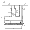
Fig. 1 is the planar structure schematic diagram of this integrated preliminary-stage rainwater flow-discarding well;
Fig. 2 is the I-I profile of Fig. 1;
Fig. 3 is the II-II profile of Fig. 1;
Among the figure: 1-rainwater inspection well, 2-storage pond, 3-swash plate, 4-manhole, 5-lower flume, 6-breather pipe, 7-abandoned stream pipe, 8-water inlet pipe, 9-reuse outlet pipe, 10-1# flow-stopping plate, 11-2# flow-stopping plate, 12-3# flow-stopping plate, 13-gripper shoe, 14-ground.
The specific embodiment
Below further describe the present invention from the angle of the early-stage rainwater process of damming:
Referring to Fig. 1, Fig. 2 and Fig. 3, integrated preliminary-stage rainwater flow-discarding well is comprised of rainwater inspection well 1 and storage pond 2.One side joint water inlet pipe 8 of described rainwater inspection well 1, opposite side is connected to reuse outlet pipe 9 relatively.Described rainwater inspection well 1 bottom is provided with lower flume 5 and the 1# flow-stopping plate 10 for the early-stage rainwater shunting, and it is other near reuse outlet pipe 9 one sides that 1# flow-stopping plate 10 is positioned at lower flume 5.Lower flume 5 is opened in the middle of the 3# flow-stopping plate 12 that arranges in rainwater inspection well 1 bottom.
Described storage pond 2 is located under the rainwater inspection well 1, and is communicated with by described lower flume 5 between the rainwater inspection well 1; Described storage pond 2 be provided with delivery port away from lower flume 5 positions, be provided with the sloping plate deposition structure at water outlet, after the sloping plate deposition structure, be connected with abandoned stream pipe 7, abandoned stream pipe 7 caliber origin or beginnings are less than end.The sloping plate deposition structure adopts 3, two swash plates 3 of two swash plates and all becomes the α angle at the bottom of the pond, is 45 ° or 60 °, and two swash plate 3 oblique parallels arrangements, and the swash plate of below has gripper shoe 13 and supports, and the swash plate of top is provided with 2# flow-stopping plate 11.
Distance computation formula between described two swash plates 3 is as follows:
b≥

Wherein: b is spacing between two swash plates, mm; D
4Be pipe with small pipe diameter abandoned stream diameter, mm is generally 40-80 ㎜; h
1Be the height of 1# flow-stopping plate, mm; h
2Be the difference in height at the bottom of top outside wall surface on the storage pond and the abandoned stream pipe pipe, mm; B is storage pond inwall width, mm.
Described lower flume 5 levels are located at rainwater inspection well 1 bottom circle centre position, and the center line of lower flume 5 is perpendicular to water inlet pipe 8 axis; The height h of described 1# flow-stopping plate 10
1Be higher than described reuse outlet pipe 9 pipes and go to the bottom and be lower than reuse outlet pipe 9 pipe centerlines, its width is described water inlet pipe 8 caliber D
1+ 200 ㎜, and over against the center of inlet tube and outlet tube.
The discharge area of described lower flume 5 equals water inlet pipe 8 areas of section, and the width of lower flume 5 gets by calculating, and computing formula is as follows:
d=(π/4)×(D
1 2/D
2)
Wherein: d is the lower flume width, mm; D
1Be rainwater water inlet pipe caliber, mm; D
2Be rainwater inspection well mineshaft diameter, mm.
Abandoned stream pipe 7 origin or beginning built-in pipe caliber D in the wall of storage pond 2
4Be water inlet pipe 8 diameter D
110%-20%, caliber D
4Be 40-80mm.Caliber became D after pipeline went out the pond body
3, D
3=300mm, abandoned stream pipe 7 is connected with the municipal wastewater system at last.
The volume of described storage pond 2 and available depth get by calculating, and computing formula is as follows respectively:
V=ψ×H×A×10
-3 h
4= h-h
3
Wherein, V is the storage pond volume, m3; ψ is runoff coefficient; H is for needing the initial rainfall amount of abandoned stream, and mm gets 3-12 ㎜; A is catchment area, i.e. the floor area of abandoned stream well effect, m
2h
4Be storage pond available depth, m; H is the design height of storage pond, is determined m by the storage pond volume; h
3Be swash plate height, wherein h
3=COS α, α are the angle at the bottom of swash plate and the pond, m;
Described storage pond 2 also is provided with manhole 4 and breather pipe 6; Described manhole 4 is respectively established one before and after the sloping plate deposition structure.Breather pipe 6 is located on the angle of storage pond.
Adopt said structure, after beginning to form runoff on the catchment area, rainwater enters rainwater inspection well 1 through water inlet pipe 8, but not in rainwater inspection well 1 interior storage, but enter storage pond 2 through lower flume 5, and current flow to abandoned stream pipe 7 through swash plate 3 again, and water level is along with rising in the well.When water level arrived the abandoned stream pipe 7 pipe end (being lowest water level), early-stage rainwater began slowly to discharge from abandoned stream pipe 7.
Because the origin or beginning caliber of abandoned stream pipe 7 is far smaller than the caliber of water inlet pipe 8, the outflow of abandoned stream pipe 7 is far smaller than the inflow of water inlet pipe 8, rainwater is in storage pond 2 interior storages, continuous formation along with rainfall runoff, storage pond 2 interior rainwater liquid levels constantly raise, and after the storage pond storage was full, rainwater was no longer by lower flume 5, directly store up in rainwater inspection well, the capacity of storage pond 2 can reclaim certain millimeter rainfall accurate Calculation on the rainwater catchment area according to specifying.
When rainwater inspection well 1 interior rainwater liquid level arrives the reuse outlet pipe 9 pipe end (being peak level), the reuse rainwater begins to flow out from reuse outlet pipe 9, since inlet tube and outlet tube, the mouth of pipe along water (flow) direction on same vertical plane, between distance short, and lower flume separates rainwater inspection well and storage pond, so form short stream between water inlet pipe and water outlet pipe, the rainwater of initial stage water quality inferiority is abandoned in storage pond, improves the reuse Rainwater Quality.
After rainfall finished rainfall runoff and stops, the inlet tube and outlet tube current stopped, and abandoned stream pipe 7 is slowly discharged storage pond 2 interior rainwater, and the solid pollutant that enters storage pond 2 with early-stage rainwater is deposited at the bottom of the storage pond pond, stopped abandoned stream after arriving lowest water level.In the whole process, the abandoned stream rainwater must flow through the 2# flow-stopping plate 11 that is provided with, swash plate 3 etc. and form the sloping plate deposition effect at the bottom of the storage pond pond, pollutant is trapped within away from abandoned stream pipe 7 one sides, so solid pollutant is difficult for stopping up the abandoned stream pipe, and abandoned stream pipe 7 origin or beginning short distance (pool wall is thick) calibers are little, the rear end caliber is large, also is easy to clear and coherent;
The solid pollutant that precipitates at the bottom of the storage pond pond, through using small-sized Sand pump discharge behind the rain water drainage several times, when the abandoned stream pipe occured to stop up, the cleaning personnel utilized submersible sewage pump with the emptying storage pond dredging abandoned stream pipe that enters of rainwater in the well.
Claims (8)
1. integrated preliminary-stage rainwater flow-discarding well is characterized in that, it is comprised of rainwater inspection well and storage pond:
One side joint water inlet pipe of described rainwater inspection well, opposite side is connected to outlet pipe relatively; Described rainwater inspection well bottom is provided with lower flume and the 1# flow-stopping plate for the early-stage rainwater shunting, and it is other near outlet pipe one side that the 1# flow-stopping plate is positioned at lower flume;
Described storage pond is located under the rainwater inspection well, and is communicated with by described lower flume between the rainwater inspection well; Described storage pond be provided with delivery port away from the lower flume position, be provided with the sloping plate deposition structure at water outlet, after the sloping plate deposition structure, be connected with the abandoned stream pipe, abandoned stream pipe caliber origin or beginning is less than end;
Described lower flume level is located at rainwater inspection well bottom circle centre position, and the central axis of lower flume is perpendicular to the water inlet pipe axis; The top of described 1# flow-stopping plate is higher than described outlet pipe pipe goes to the bottom and is lower than the outlet pipe pipe centerline, and its width is described water inlet pipe caliber D
1+ 200 ㎜, and the 1# flow-stopping plate is over against the center of inlet tube and outlet tube.
2. integrated preliminary-stage rainwater flow-discarding well according to claim 1, it is characterized in that: the discharge area of described lower flume equals the water inlet pipe area of section, and the width of lower flume gets by calculating, and computing formula is as follows:
d=(π/4)×(D
1 2/D
2)
Wherein: d is the lower flume width, mm; D
1Be rainwater water inlet pipe caliber, mm; D
2Be rainwater inspection well mineshaft diameter, mm.
3. integrated preliminary-stage rainwater flow-discarding well according to claim 1, it is characterized in that: the sloping plate deposition structure of the water outlet of described storage pond adopts two swash plates, two swash plates with all become the α angle at the bottom of the pond, it is 45 ° or 60 °, and two swash plate oblique parallels are arranged, the swash plate of below has gripper shoe and supports, and the swash plate of top is provided with the 2# flow-stopping plate;
Distance computation formula between described two swash plates is as follows:
b≥

Wherein: b is spacing between two swash plates, mm; D
4Be pipe with small pipe diameter abandoned stream diameter, be 40-80 ㎜; h
1Be the height of 1# flow-stopping plate, mm; h
2Be the difference in height at the bottom of top outside wall surface on the storage pond and the abandoned stream pipe pipe, mm; B is storage pond inwall width, mm.
4. integrated preliminary-stage rainwater flow-discarding well according to claim 1 is characterized in that: abandoned stream pipe origin or beginning built-in pipe caliber D in the pool wall of regulating and storing
4Be water inlet pipe diameter D
110%-20%, caliber became D after pipeline went out the pond body
3, the abandoned stream pipe is connected with the municipal wastewater system at last.
5. integrated preliminary-stage rainwater flow-discarding well according to claim 4 is characterized in that: described abandoned stream pipe caliber D
3=300mm, caliber D
4Be 40-80mm.
6. integrated preliminary-stage rainwater flow-discarding well according to claim 1 is characterized in that: the volume of described storage pond and available depth get by calculating, and computing formula is distinguished as follows:
V=ψ×H×A×10
-3 h
4= h-h
3
Wherein, V is the storage pond volume, m
3ψ is runoff coefficient; H is for needing the initial rainfall amount of abandoned stream, and mm gets 3-12 ㎜; A is catchment area, i.e. the floor area of abandoned stream well effect, m
2h
4Be storage pond available depth, m; H is the design height of storage pond, is determined m by the storage pond volume; h
3Be swash plate height, wherein h
3=COS α, α are the angle at the bottom of swash plate and the pond, m.
7. integrated preliminary-stage rainwater flow-discarding well according to claim 1, it is characterized in that: described storage pond is provided with manhole and breather pipe; Described manhole is respectively established one before and after the sloping plate deposition structure.
8. adopt integrated preliminary-stage rainwater flow-discarding well claimed in claim 1 to carry out the method for rain water drainage, its process is as follows:
1) after beginning to form runoff on the catchment area, rainwater enters rainwater inspection well through water inlet pipe, enters storage pond through lower flume again;
2) current all pass through between two swash plates in the storage pond, form the sloping plate deposition effect, and the solid pollutant interception away from abandoned stream pipe one side, is guaranteed that the abandoned stream pipe flows through without solid pollutant, avoid pipe with small pipe diameter to stop up;
3) because abandoned stream pipe origin or beginning caliber is far smaller than the caliber of water inlet pipe, the outflow of abandoned stream pipe is far smaller than the inflow of water inlet pipe, and early-stage rainwater begins to store in storage pond, with the rising of rainwater liquid level, the storage pond storage is full, and rainwater begins to store in rainwater inspection well;
4) when the water fender top on the rainwater liquid level arrival lower flume in the rainwater inspection well, the reuse rainwater begins to be flowed out by outlet pipe, because the distance between the inlet tube and outlet tube mouth of pipe is short, and lower flume separates rainwater inspection well and storage pond, effectively stoped rainwater inspection well to exchange with current between the storage pond, rainwater forms short stream between inlet tube and outlet tube, the rainwater of initial stage water quality inferiority is abandoned in storage pond, improves the reuse Rainwater Quality;
5) when rainfall runoff stops, the current between the inlet tube and outlet tube stop, and the abandoned stream pipe is slowly discharged rainwater in the storage pond, stop after arriving effective lowest water level;
6) solid waste that enters in the storage pond with early-stage rainwater precipitates at the bottom of the pond, after after a while, discharge with small-sized Sand pump, when the abandoned stream pipe occurs to stop up, the cleaning personnel enter the abandoned stream pipe of storage pond dredging caliber tubule section, the pre-buried pipe with small pipe diameter of abandoned stream pipe origin or beginning is apart from weak point, only have storage pond wall thickness length, be convenient to dredge blockage.
Priority Applications (1)
| Application Number | Priority Date | Filing Date | Title |
|---|---|---|---|
| CN2010106039115A CN102102392B (en) | 2010-12-24 | 2010-12-24 | Integrated initial rainwater draining well and method for draining rainwater |
Applications Claiming Priority (1)
| Application Number | Priority Date | Filing Date | Title |
|---|---|---|---|
| CN2010106039115A CN102102392B (en) | 2010-12-24 | 2010-12-24 | Integrated initial rainwater draining well and method for draining rainwater |
Publications (2)
| Publication Number | Publication Date |
|---|---|
| CN102102392A CN102102392A (en) | 2011-06-22 |
| CN102102392B true CN102102392B (en) | 2013-03-27 |
Family
ID=44155431
Family Applications (1)
| Application Number | Title | Priority Date | Filing Date |
|---|---|---|---|
| CN2010106039115A Expired - Fee Related CN102102392B (en) | 2010-12-24 | 2010-12-24 | Integrated initial rainwater draining well and method for draining rainwater |
Country Status (1)
| Country | Link |
|---|---|
| CN (1) | CN102102392B (en) |
Cited By (1)
| Publication number | Priority date | Publication date | Assignee | Title |
|---|---|---|---|---|
| FR3119850A1 (en) * | 2021-02-14 | 2022-08-19 | Biesse Philippe | Compact bedload trap. |
Families Citing this family (12)
| Publication number | Priority date | Publication date | Assignee | Title |
|---|---|---|---|---|
| CN103806525A (en) * | 2012-11-09 | 2014-05-21 | 烟台水泰和水科技有限公司 | Gantry self-flushing device for rainwater storage tank |
| CN103193340B (en) * | 2013-04-16 | 2014-02-12 | 上海市城市建设设计研究总院 | Regulation and storage pond with processing function |
| CN103526820B (en) * | 2013-10-15 | 2014-12-31 | 天津大学 | Eccentric sand clock type diversion ditch |
| CN103726570B (en) * | 2014-01-24 | 2015-07-08 | 重庆大学 | Spiral-flow type hydraulically controlled rainwater intercepting and abandoning switch well system |
| CN103866846B (en) * | 2014-02-21 | 2015-06-17 | 武汉圣禹排水系统有限公司 | Primary rainwater separation method |
| CN104695543A (en) * | 2014-12-04 | 2015-06-10 | 洼石环境工程(上海)有限公司 | Bidirectional hydraulic door type automatic flushing and desilting system for rainwater storage tank as well as application |
| CN104763038B (en) * | 2015-04-10 | 2016-04-13 | 浙江省水利水电勘测设计院 | A kind of early-stage rainwater stream abandoning system and abandoned stream method thereof |
| CN107190842B (en) * | 2017-05-27 | 2019-07-16 | 武汉圣禹排水系统有限公司 | A kind of control method for shunting of accurately removing contamination for rainwater |
| CN108245939A (en) * | 2018-02-09 | 2018-07-06 | 大同煤矿集团有限责任公司 | Coal slime precipitation process system and water discharge method and coal mud clearing method in draining |
| CN109162342B (en) * | 2018-07-20 | 2023-11-14 | 浙江绿维环境股份有限公司 | Intelligent multi-grid rain and sewage intercepting well |
| CN109339213A (en) * | 2018-12-07 | 2019-02-15 | 江苏百海环保科技有限公司 | A kind of ecology underground river rainwater regulating pondage system |
| CN112554325A (en) * | 2020-11-25 | 2021-03-26 | 北京易成市政工程有限责任公司 | Rainwater reservoir and construction process thereof |
Citations (3)
| Publication number | Priority date | Publication date | Assignee | Title |
|---|---|---|---|---|
| CN101105039A (en) * | 2006-07-12 | 2008-01-16 | 葛敬 | Rainwater primary fluid-discarding device |
| CN101736773A (en) * | 2008-11-25 | 2010-06-16 | 北京科净源科技股份有限公司 | Control device for safely abandoning and diverting flow of rain water |
| CN201981631U (en) * | 2010-12-24 | 2011-09-21 | 重庆大学 | Integrated preliminary-stage rainwater flow-discarding well |
Family Cites Families (1)
| Publication number | Priority date | Publication date | Assignee | Title |
|---|---|---|---|---|
| EP1855775A1 (en) * | 2005-03-05 | 2007-11-21 | Oekag Wassertechnik (Schweiz) AG | Method and device for the purification of rain drainage water |
-
2010
- 2010-12-24 CN CN2010106039115A patent/CN102102392B/en not_active Expired - Fee Related
Patent Citations (3)
| Publication number | Priority date | Publication date | Assignee | Title |
|---|---|---|---|---|
| CN101105039A (en) * | 2006-07-12 | 2008-01-16 | 葛敬 | Rainwater primary fluid-discarding device |
| CN101736773A (en) * | 2008-11-25 | 2010-06-16 | 北京科净源科技股份有限公司 | Control device for safely abandoning and diverting flow of rain water |
| CN201981631U (en) * | 2010-12-24 | 2011-09-21 | 重庆大学 | Integrated preliminary-stage rainwater flow-discarding well |
Cited By (1)
| Publication number | Priority date | Publication date | Assignee | Title |
|---|---|---|---|---|
| FR3119850A1 (en) * | 2021-02-14 | 2022-08-19 | Biesse Philippe | Compact bedload trap. |
Also Published As
| Publication number | Publication date |
|---|---|
| CN102102392A (en) | 2011-06-22 |
Similar Documents
| Publication | Publication Date | Title |
|---|---|---|
| CN102102392B (en) | Integrated initial rainwater draining well and method for draining rainwater | |
| CN105130055B (en) | Rainwater-collecting purified treatment reclaiming system | |
| CN102774896A (en) | Integral purification device and method for particles in rain and sewage | |
| CN101967841A (en) | Method and device for implementing primary rainwater closure in municipal network system | |
| CN209011273U (en) | A kind of buried rainwater-collecting reclaiming system | |
| CN205776662U (en) | A kind of rain water drainage system | |
| CN107587580A (en) | A kind of band surge bottom-open type weir gate and pump row drainage system and water discharge control method | |
| CN206109974U (en) | Bridge drainage system | |
| CN207760989U (en) | A kind of pump discharges into water system | |
| CN107605005A (en) | A kind of drainage system and water discharge control method arranged with waterpower non-return weir gate and pump | |
| CN207582618U (en) | A kind of pump discharges into water system | |
| CN203878648U (en) | Multifunctional rainwater collecting system | |
| CN106522354B (en) | It is provided with the intercepted drain pumping plant of inclined plate or inclined tube separation | |
| CN106902569B (en) | A kind of collection pretreatment system of city overland runoff initial rainwater | |
| CN201981631U (en) | Integrated preliminary-stage rainwater flow-discarding well | |
| CN209412895U (en) | A kind of landscape rainwater-collecting reclaiming system | |
| CN205242500U (en) | System of recycling that handles is collected to rainwater | |
| CN201826345U (en) | Tubular rainwater discarding device | |
| CN104631612B (en) | Flushing system for rainwater regulation and storage tanks | |
| CN206428911U (en) | Mechanical float ball flow abandoning apparatus, rain water collecting system and roofing cooling structure | |
| CN103422566B (en) | Multifunctional flow-dividing well | |
| CN201840915U (en) | Grit chamber for sewage treatment | |
| CN103741785B (en) | A kind of rain water drainage part flow arrangement | |
| CN203769039U (en) | Rainwater storage and drainage system for urban road | |
| CN209011283U (en) | A kind of sponge novel urban rainwater separate system |
Legal Events
| Date | Code | Title | Description |
|---|---|---|---|
| C06 | Publication | ||
| PB01 | Publication | ||
| C10 | Entry into substantive examination | ||
| SE01 | Entry into force of request for substantive examination | ||
| C14 | Grant of patent or utility model | ||
| GR01 | Patent grant | ||
| CF01 | Termination of patent right due to non-payment of annual fee | ||
| CF01 | Termination of patent right due to non-payment of annual fee |
Granted publication date: 20130327 Termination date: 20161224 |