CN102076547B - Combination of a trolley for carrying cleaning materials and bucket structure - Google Patents
Combination of a trolley for carrying cleaning materials and bucket structure Download PDFInfo
- Publication number
- CN102076547B CN102076547B CN2009801247761A CN200980124776A CN102076547B CN 102076547 B CN102076547 B CN 102076547B CN 2009801247761 A CN2009801247761 A CN 2009801247761A CN 200980124776 A CN200980124776 A CN 200980124776A CN 102076547 B CN102076547 B CN 102076547B
- Authority
- CN
- China
- Prior art keywords
- hand barrow
- barrel structure
- wheel
- main structure
- composite set
- Prior art date
- Legal status (The legal status is an assumption and is not a legal conclusion. Google has not performed a legal analysis and makes no representation as to the accuracy of the status listed.)
- Expired - Fee Related
Links
Images


Classifications
-
- B—PERFORMING OPERATIONS; TRANSPORTING
- B62—LAND VEHICLES FOR TRAVELLING OTHERWISE THAN ON RAILS
- B62B—HAND-PROPELLED VEHICLES, e.g. HAND CARTS OR PERAMBULATORS; SLEDGES
- B62B3/00—Hand carts having more than one axis carrying transport wheels; Steering devices therefor; Equipment therefor
- B62B3/10—Hand carts having more than one axis carrying transport wheels; Steering devices therefor; Equipment therefor characterised by supports specially adapted to objects of definite shape
- B62B3/104—Hand carts having more than one axis carrying transport wheels; Steering devices therefor; Equipment therefor characterised by supports specially adapted to objects of definite shape the object being of cylindrical shape, e.g. barrels, buckets, dustbins
-
- B—PERFORMING OPERATIONS; TRANSPORTING
- B62—LAND VEHICLES FOR TRAVELLING OTHERWISE THAN ON RAILS
- B62B—HAND-PROPELLED VEHICLES, e.g. HAND CARTS OR PERAMBULATORS; SLEDGES
- B62B2202/00—Indexing codes relating to type or characteristics of transported articles
- B62B2202/22—Flexible bags, e.g. for rubbish
-
- B—PERFORMING OPERATIONS; TRANSPORTING
- B62—LAND VEHICLES FOR TRAVELLING OTHERWISE THAN ON RAILS
- B62B—HAND-PROPELLED VEHICLES, e.g. HAND CARTS OR PERAMBULATORS; SLEDGES
- B62B2202/00—Indexing codes relating to type or characteristics of transported articles
- B62B2202/50—Cleaning or gardening articles
-
- B—PERFORMING OPERATIONS; TRANSPORTING
- B62—LAND VEHICLES FOR TRAVELLING OTHERWISE THAN ON RAILS
- B62B—HAND-PROPELLED VEHICLES, e.g. HAND CARTS OR PERAMBULATORS; SLEDGES
- B62B2202/00—Indexing codes relating to type or characteristics of transported articles
- B62B2202/90—Vehicles
-
- B—PERFORMING OPERATIONS; TRANSPORTING
- B62—LAND VEHICLES FOR TRAVELLING OTHERWISE THAN ON RAILS
- B62B—HAND-PROPELLED VEHICLES, e.g. HAND CARTS OR PERAMBULATORS; SLEDGES
- B62B2207/00—Joining hand-propelled vehicles or sledges together
- B62B2207/02—Joining hand-propelled vehicles or sledges together rigidly
-
- B—PERFORMING OPERATIONS; TRANSPORTING
- B62—LAND VEHICLES FOR TRAVELLING OTHERWISE THAN ON RAILS
- B62B—HAND-PROPELLED VEHICLES, e.g. HAND CARTS OR PERAMBULATORS; SLEDGES
- B62B5/00—Accessories or details specially adapted for hand carts
- B62B5/08—Children's seats ; Seats or supports for other persons
- B62B5/087—Platforms to stand upon
Abstract
Provided is a combination of a trolley for carrying cleaning materials and a bucket structure (12), the trolley including a main trolley structure (10), front wheels (19) and back wheels (18), a housing (25), and a handle structure (20) by means of which the main trolley structure (10) may be guided over a floor on the wheels (19, 18). The bucket structure (12) includes a container (25) for containing cleaning liquid and at least three wheels (26, 27) whereby the bucket structure (12) is stably moveable over the floor independently of the trolley (10); the housing (25) of the main trolley structure (25) includes an accommodation space (30) into which the bucket structure (12) may be wheeled; there is provided a retaining device (41;45) for retaining at least a part of the bucket structure (12) in the accommodation space (30) and which is readily releasable to permit subsequent separation of the trolley (10) and bucket structure (12); and the housing (25) substantially surrounds the accommodation space (30) on at least two sides and the trolley (10) includes at least one storage area (16, 17) for carrying materials used for cleaning.
Description
Specification sheets
The present invention relates to a kind of hand barrow for the carrying cleaning material and the composite set of barrel structure.
Patent US 7104556 before for example own from me is known, bucket is connected in hand barrow, thereby these two equipment can be moved together from one place to another, and described bucket leans on its oneself wheel and additionally removable.Described bucket is pushed or is pulled in the rear end of hand barrow at the front end of hand barrow, and still, when the mobile hand barrow that has connected and bucket, this layout can cause bucket unstable, in the time of especially on rugged and rough ground.In addition, the hand barrow that has connected and bucket can cause vehicle long.
according to a first aspect of the present invention, I provide a kind of hand barrow for the carrying cleaning material and the composite set of barrel structure, described hand barrow comprises the hand barrow main structure, described hand barrow main structure comprises front end, rear end and a counter-lateral quadrents, described hand barrow comprises the front-wheel that is positioned at described front end and the trailing wheel that is positioned at described rear end, housing, and grip structure, utilize described wheel bootable described hand barrow main structure on the ground by described grip structure, described barrel structure comprises be used to the container that holds clean liquid and three wheels at least, described barrel structure can be independent of on the ground described hand barrow and stably move thus, the described housing of described hand barrow main structure comprises spatial accommodation, at least a portion of described barrel structure can advance to described spatial accommodation by wheel from described front end or from a side of described side, and have at least a portion with described barrel structure and remain on holding device in described spatial accommodation, and described holding device can easily be taken apart, described hand barrow separates with described barrel structure to allow subsequently, described housing is at described front end, at least two upper basic described spatial accommodations that surround in described rear end and described counter-lateral quadrents, and, described hand barrow comprises that at least one is used to carry the storage area of Clean-material.
In whole specification sheets, by term " wheel " or " a plurality of wheel ", we have comprised castor.
By the present invention, in the time of in described barrel structure is in described spatial accommodation, along with the wheel of described hand barrow by described hand barrow moves, described barrel structure moves by the wheel of described barrel structure easily, uses but described bucket can be independent of described hand barrow when needed.When at least a portion of described barrel structure is contained in described spatial accommodation, the layout of dragging in the hand barrow back with bucket or pushing away bucket in the hand barrow front is compared, bucket mobile pattern together with hand barrow is improved, as top definite known proposal, required this functional although described hand barrow can still provide.
The essence of described barrel structure is not crucial for the present invention, as long as described barrel structure can be advanced by wheel from the described front end of hand barrow or the side described side and be entered and remain in described spatial accommodation, and described barrel structure can have wheel and the container of one thus, perhaps described container can be arranged on the chassis of the described wheel with described barrel structure, and described container and described chassis are separable, for example to be used for filling clean liquid (for example water) from water cock.
In a layout, described barrel structure comprises and is arranged in described container or is arranged on wringing mechanism on described container, described wringing mechanism comprises the wringing handle, and described wringing handle is movably so that the member (for example wringing mop) of mobile described wringing mechanism.Typically, described wringing mechanism is flexible in order to force described handle towards lifting the position.In one embodiment, in the time of in described barrel structure is accommodated in described spatial accommodation at least in part, described wringing handle can be forced to the holding member of described hand barrow main structure and coordinate, and to provide, described barrel structure is remained on described holding device in described spatial accommodation.
In another example, described hand barrow main structure can comprise retaining member, and described retaining member can move to the holding position from favorite places; At described favorite places, described barrel structure can advance in described spatial accommodation by wheel; And in described holding position, described retaining member engages with described barrel structure, so that described holding device to be provided.For example, described retaining member can be relatively described hand barrow main structure pivotable bar between its favorite places and holding position.
In a layout, described grip structure can relatively described hand barrow main structure move either up or down to control position from favorite places; At described control position, described grip structure is applicable to promote and/or pull and guide described hand barrow.Ideally, when described grip structure is in its favorite places lower time, described hand barrow main structure is contained in not significantly in the overlay area, space greater than described housing substantially.Like this, when described grip structure is in its favorite places lower time, especially compact hand barrow can be provided, and no matter whether described barrel structure is contained in described housing, thereby when storing or parking described hand barrow at least, described hand barrow occupies minimum ground space.
Yet, if necessary, when described grip structure is in its control position, described grip structure can be used as the strut member be used to the container that is hanging (for example rubbish container or refuse bag), in the time need to advancing to spatial accommodation by wheel described Hand pulling vehicle from the end that described handle is set, described strut member may need to be disassembled.
Described grip structure can be arranged on described front end or the described rear end of described hand barrow main structure.Described barrel structure is by from the described front end of described hand barrow main structure or advance by wheel and can be accommodated in described spatial accommodation from a side, but and the holding element of the described hand barrow main structure of described barrel structure butt, thereby described barrel structure can be maintained in described spatial accommodation and between described holding element and described holding device.
If necessary, described holding element can separate with the other parts of described hand barrow main structure with the second place in primary importance and can engage with the other parts of described main hand barrow; In described primary importance, when the described front end of described hand barrow main structure or a side advanced to described spatial accommodation by wheel, described holding element kept described barrel structure when described barrel structure; In the described second place, from the rear end of described hand barrow main structure or opposite side when advancing to described spatial accommodation by wheel, described holding element keeps described barrel structure when described barrel structure.
Certainly, large-scale hand barrow main structure can be contained in more than one barrel structure in described housing, and each barrel structure is in its oneself spatial accommodation as required.In this case, barrel structure can advance to by wheel from the front end of described hand barrow main structure its spatial accommodation and another barrel structure can advance to by wheel from a side of described hand barrow main structure its spatial accommodation, and perhaps each barrel structure in a pair of barrel structure can advance to described spatial accommodation by wheel from the respective side of described hand barrow.
Described hand barrow main structure can arrange strut member (for example platform and/or framing member) at one of them or both places of described rear end and described front end, and described strut member is used for being carried on storage container on described strut member (for example only sewage disposer) for example or another article.
In an example, a strut member in described strut member or described a plurality of strut member can be folded to from " use " position of described bottom the favorite places on top.At least one strut member in described strut member or described a plurality of strut member can have its oneself wheel.
According to a second aspect of the present invention, I have offered the cleaning hand barrow for the described composite set of first aspect present invention.
according to a third aspect of the present invention, we provide a kind of hand barrow for the carrying cleaning material, described hand barrow comprises the hand barrow main structure, described hand barrow main structure comprises front end, rear end and a counter-lateral quadrents, described hand barrow comprises the front-wheel that is positioned at described front end and the trailing wheel that is positioned at described rear end, and the reliable described wheel of described hand barrow moves on the ground thus, and described hand barrow comprises carrying structure, described carrying structure is from the described front end of described hand barrow main structure, in described rear end and described side one is upper protruding, described carrying structure is used for installing the bogey that will be suspended on described carrying structure, and described hand barrow comprises strut member, described strut member can and lift between the position folded in " use " position of bottom in one of them place of described rear end and described side, " use " position in described bottom, at least one support wheel ground-engaging of described strut member, and in the described position of lifting, the described wheel of described strut member is lifted built on stilts, wherein, described strut member can be locked in " use " position of the bottom of described strut member.
It will be appreciated that, for the hand barrow of relatively little overlay area, space and on the described hand barrow main structure for outwardly directed carrying structure, when loading the upper bogey that hangs, this can cause hand barrow unstable.Yet the end identical with described bogey by described strut member being arranged on described hand barrow main structure or side and described strut member have its oneself wheel or a plurality of wheel, and described strut member will support described hand barrow for this stability.
Described strut member can be locked in " use " position of the bottom of described strut member by suitable mechanism, think that described hand barrow provides maximum support; When thinking upwards folding described strut member (for example in order to reduce the overlay area, space of described hand barrow, so that collection), described suitable structure can easily be taken apart.
Ideally, described carrying structure is handle, can be directed on the ground by the described hand barrow of described handle.Ideally, the relatively described hand barrow main structure of described handle self can move to control position from favorite places; At described favorite places, bogey is not installed; At described control position, described bogey can be installed into and hangs on described carrying structure.
The cleaning hand barrow of a third aspect of the present invention can have any feature of the hand barrow of composite set of the present invention.
Now with reference to accompanying drawing, embodiments of the invention are described, in the accompanying drawings:
Fig. 1 is the schematic side elevation according to the composite set of the hand barrow main structure of a first aspect of the present invention and barrel structure;
Fig. 1 b is the birds-eye view of the composite set of Fig. 1;
Fig. 2 be with Fig. 1 b similarly but be the view of another embodiment;
Fig. 3 is the schematic perspective view of another embodiment;
Fig. 4 a is the schematic perspective view according to the hand barrow of third aspect present invention, and the strut member of " use " position that is in the bottom of hand barrow is shown;
Fig. 4 b is the alternative view of the hand barrow of Fig. 4 a, being in of hand barrow is shown lifts the favorite places strut member;
Fig. 5 a is the schematic side elevation of another embodiment; And
Fig. 5 b is the explanatory view of the bottom side of Fig. 5 a.
At first with reference to Fig. 1 and Fig. 1 b, show the composite set of hand barrow main structure 10 and barrel structure 12.
Hand barrow main structure 10 comprises the box frame that is made of vertical framing member 12a and 12b (being in this example four) and horizontal frame member 13a, 13b, 13c, described box frame provides housing 15 and at least one zone for storage clean article and material, for example be positioned at the pallet 16 of upper end, and the dividing plate 17 between pallet 16 and framing member 13c, if necessary, dividing plate 17 can be installed another pallet (sentencing dotted line at 16a represents).In this example, hand barrow main structure 10 still if necessary, can comprise sidewall and/or end wall for substantially opening wide framework.Shown framework is exemplary purely, and can make many modifications within the scope of the invention.
In this example, hand barrow main structure 10 comprises four wheels, be a pair of large trailing wheel 18 and a pair of front-wheel or castor 19, there is a large trailing wheel 18 in each rear end corner of hand barrow main structure 10, and in this example, described is tight pulley around common rotating shaft rotation to large trailing wheel 18 trailing wheels, in each front end corner of hand barrow main structure 10, a front-wheel or castor 19 is arranged.
If necessary, as shown in Fig. 1 dotted line, when grip structure 20 was in its operating position, container (for example rubbish container or refuse bag 22) can be suspended on grip structure 20.Grip structure 20 can be provided with hook or similar formation, so that this operation.
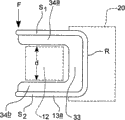
According to the present invention, by described barrel structure is advanced in spatial accommodation 30 by wheel, at least a portion of barrel structure 12 can be accommodated in the spatial accommodation 30 that the housing 15 by hand barrow main structure 10 provides, in this example, at first trailing wheel 27 goes from the front end F of the hand barrow main structure 10 rear end R that grip structure 20 stretches out when being in the grip structure operating position relatively.For this reason, nethermost horizontal frame member 13c does not connect at the front end F place of hand barrow main structure 10 but accommodation section 32 is provided between them, accommodation section 32 comprises holding element 33 and side member 34a, 34b, holding element 33 in or extend between framing member 13C towards hand barrow main structure 10 rear end R, side member 34a, 34b are partitioned into just wide than the respective transversal size d that is contained in the barrel structure 12 between side member 34a, 34b.Thus, in the time of in being in spatial accommodation 30, barrel structure 12 both sides 51,52 and rear end R in each place surrounded by described housing.
In this example, the cross member at least 44 of hand barrow main structure 10 or described framework (being positioned to towards trolley structure 10 front end F) provides a part that is used for barrel structure 12 is remained on the holding device in spatial accommodation 30.Along with barrel structure 12 advances in spatial accommodation 30 by wheel, wringing handle 41 needs antagonistic spring power by downward pivotable; And wringing handle 41 resilience that will make progress, to engage cross member 44, thus barrel structure 12 is captured in spatial accommodation 30; Until the user manually takes wringing handle 41 and cross member 44 apart and discharges wringing handle 41.Thus, in this example, wringing handle 41 provides holding device, and barrel structure 12 is maintained between holding device 41 and holding element 33.
Be possible for other alternative arrangement that barrel structure 12 is remained on spatial accommodation 30, this may relate to employing or not adopt wringing handle 41.For example, hand barrow main structure 10 can be provided with the pivotable retaining member, and described pivotable retaining member can and remain on barrel structure 12 in content space 30 from the container that engages barrel structure 12 25 of favorite places bottom.
If necessary, as shown in Fig. 1 dotted line, front end F place in hand barrow main structure 10 can arrange needed strut member 46, strut member 46 be used for supported and suspended rubbish container or refuse bag 22a (as outside the sack 22 that supports and illustrate by grip structure 20 or alternative).If necessary, strut member 46 can be as grip structure 20 relative hand barrow main structure 10 collapsible, to be collected in cupboard when hand barrow or to make the overlay area, space of hand barrow minimum when being parked in collection space.
As mentioned above, in this embodiment, for along with trolley structure 10 and barrel structure 12 are advanced by wheel on the ground together and barrel structure 12 is remained in spatial accommodation 30, pivotable retaining member bottom engage barrel structure 12 to operating position, but wringing handle 41 can be used alternatingly together with cross member 44 as required.
Fig. 2 shows another embodiment, and wherein, the parts corresponding with those parts that illustrated are represented by identical Reference numeral.In Fig. 2, hand barrow main structure 10 can be suitable for from front end F containment drum structure 12.In Fig. 2, with solid line, holding element 33a is shown, holding element 33a is positioned at hand barrow main structure 10 rear end R, thus barrel structure 12 can advance in spatial accommodation 30 by wheel from front end F with reference to the similar mode of mode of Fig. 1 explanation.Yet in this example, holding element 33a is connected in the remainder of trolley structure 10 by one or more removable connecting element 56a, and holding element 33a can be disassembled, change and relative hand barrow main structure 10 is reorientated.For example, alternately, by the removable connecting element 56a at hand barrow main structure 10 front end F places, described holding element can be positioned in position shown in dotted lines in Figure 2.In addition, in this embodiment, holding element 33a is provided with adaptor union 55, adaptor union 55 can be used for another pulley structure (for example another barrel structure 56 or belt wheel platform) being connected in hand barrow main structure 10 and as one man moving together with hand barrow main structure 10 (and barrel structure 12, in the time of in being present in spatial accommodation 30).
In each embodiment in shown embodiment, can see, the container 25 of barrel structure 12 has the upper limb of protracting 60.Especially can see in Fig. 1, when barrel structure 12 was accommodated in spatial accommodation 30, projecting edge 60 reached the position of described cart frame front.Thus easily, clean article can be accommodated in container 25 together with long handle (for example mop that Fig. 2 represents in 62 places), upwardly extending described handle of while or a plurality of handle, wherein, described handle or a plurality of handle can by be arranged in hand barrow main structure 10, other or on retainer 63 keep or support at least.Thus, when hand barrow main structure 10 and barrel structure 12 (in spatial accommodation 30) were advanced by wheel together on the ground, especially wet mop can be transported in container 25, and their handle is by excellent support simultaneously.
With reference to Fig. 3, trolley structure 10 is shown, wherein barrel structure 12 can advance to described spatial accommodation by wheel from a side S1 of housing 15, and the described framework of described trolley structure all has cross member at the front end F of housing 15 and rear end R and opposite side S2 place.
The accommodation section 32 of trolley structure 10 has along the holding element 33 of housing 15 side S2 (relative by the position that wheel advances in spatial accommodation 30 with housing 15 permission barrel structures 25) and along the front end F of housing 15 and side member 34a, the 34b of rear end R, so that described accommodation section 32 to be provided.
In this example, holding device is provided by wringing handle 41 and the cross member 44 that extends along trolley structure 10 1 side S1.
In addition, in this embodiment, as in example in front, grip structure 20 can upwards be folded to favorite places, and pallet 16 is arranged on the upper end of trolley structure 10, and the pallet 16 of pallet 16 ratios such as Fig. 1 is darker.In addition, be similar to trolley structure 10 in the figure of front on 10 functions of the trolley structure in Fig. 6.
The comparable form that illustrates of trolley structure 10 in Fig. 6 is longer, a pair of thereby (or more than a pair of) barrel structure 12 can be contained in spatial accommodation 30 or spatial accommodation separately, in this case, if holding element 33 extends along side S1, each barrel structure 12 can from housing 15 1 side S1 opposite side S2 advances to described by wheel or its spatial accommodation 30 separately.In another example, barrel structure 12 can be from trolley structure 10 1 side S1 and another barrel structure can from trolley structure opposite side S2 advance to described by wheel or its spatial accommodation 30 separately in.
In each example, according to the present invention, although barrel structure 12 remains in spatial accommodation 30, when promoting on the ground or pulling trolley structure 10, barrel structure 12 moves by its wheel or castor 26,27.
With reference to Fig. 4 a and Fig. 4 b, the hand barrow according to third aspect present invention is shown, but described hand barrow can use together with the belt wheel barrel structure with the first and second aspects combinations of the present invention in this example.This is as previous embodiments, the spatial accommodation that described hand barrow provides barrel structure to advance and to enter by wheel.Yet, can be unsuitable for being combined with the belt wheel barrel structure according to the hand barrow of third aspect present invention.In this case, described hand barrow need not to have spatial accommodation 30.
In Fig. 4 a and Fig. 4 b, represented by identical Reference numeral with the similar parts of parts of hand barrow in the figure of front.
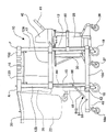
Described hand barrow has and the similar hand barrow main structure 10 of hand barrow main structure shown in Figure 3, and hand barrow main structure 10 comprises grip structure 20, and in this example, grip structure 20 is protruding towards hand barrow rear end R.Can be folded between the favorite places of the bottom that grip structure 20 is seen in " use " condition of lifting shown in Fig. 4 a with as Fig. 4 b; Lifting under " use " condition, bogey (for example rubbish container or refuse bag) 22 can be installed by grip structure 20, thereby bogey 22 is suspended on grip structure or carrying structure 20.The position of bogey 22 is shown in broken lines in Fig. 4 a and Fig. 4 b.
For the rubbish container that supports loading or the weight of refuse bag 22, grip structure 20 lifts under the position and can lock by required lockout mechanism arbitrarily at it.
Hand barrow main structure 10 carries front-wheel 10 and carries trailing wheel 18 at R place, rear end at front end F place.Hand barrow main structure 10 has side S1, the S2 between front end F and rear end R.Wheel 18,19 makes hand barrow be guided by grip structure 20 and to move on the ground.
According to a third aspect of the present invention, described hand barrow comprises the strut member 48 that is positioned at rear end, and strut member 48 can be folded lifting between the position shown in " use " position of the bottom shown in Fig. 4 a and Fig. 4 b in R place, rear end; " use " position in the bottom, the support wheel 18a ground-engaging of strut member 48; Lifting the position, the support wheel 18a of strut member 48 is lifted built on stilts.Foundation needs, and strut member 48 can be platform or is one or more framing member.In this example, strut member 48 carries one wheel pairs or the castor 18a at the R place, utmost point rear end that is positioned at trolley structure 10.Thus, when strut member 48 folded bottom, trolley structure 10 has three pairs of wheel/ castors 18,18a, 33.
To recognize, the hand barrow main structure 10 of Fig. 4 a and the hand barrow of Fig. 4 b has relative little overlay area, space.Carrying structure (namely be in this example grip structure 20, grip structure 20 is protruding from hand barrow main structure 10) with the bogey (for example rubbish container or refuse bag) 22 that hangs and loaded can cause hand barrow unstable.Yet, by the R place, rear end that bogey 22 is set in hand barrow main structure 10, strut member 48 (strut member 48 has its wheel or a plurality of wheel 18a) being set, strut member 48 will be for this stability support trolley on the ground.
Support maximum in order to make, preferably, strut member 48 can be locked in " use " position of the bottom of described strut member by suitable mechanism, when can making progress folding support member 48 in the position towards Fig. 4 b, described suitable mechanism can easily be taken apart, for example in order to reduce the overlay area, space of hand barrow, so that collection.
In this example, strut member 48 is articulated in hand barrow main structure 10 by a pair of movable joint strut 71,72, " use " position of the described bottom that strut member 48 can be locked in described strut member to movable joint strut 71,72 but can allow the upwards folding rear side R that is against of strut member 48.Any suitable required pivotable/lockout mechanism can be set.
In the embodiment that revises, described strut member can only have single wheel 18a or more than a pair of support wheel 18a.Strut member 48 can be hinged, pivot joint, movable joint connect, and perhaps otherwise can and lift between the position folded in the position of bottom.
Although wish that carrying structure 20 is grip structure 20 (can guide on the ground described trolley structure by grip structure 20), but in another embodiment, carrying structure 20 can be independent of handle and be arranged on the front end F of hand barrow main structure 20 for example or even at a side or the opposite side of side S1, S2.In all cases, can cause the unsettled tilting force of hand barrow in order for example to offset because loading bogey 22, strut member 48 is arranged on same end R, F or the same side S1, the S2 of main hand barrow 10.
Although strong preferred grip/carrying structure 20 is folding as mentioned above, but in another example, handle/carrying structure 20 can be fixed in hand barrow main structure 10, although in the sort of situation, the overlay area, space of hand barrow can not be reduced to the degree shown in Fig. 7 b for collection.
In this example, strut member 48 provides the platform that can carry clean article, but in another example, strut member 48 can be the framework that simply carries support wheel or a plurality of support wheel 19a.
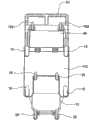
Fig. 5 a and Fig. 5 b show and the similar trolley structure 10 of trolley structure shown in Fig. 4 a and Fig. 4 b.Hand barrow main structure 10 has front end F, front-wheel 19, rear end R and trailing wheel 18.Described hand barrow comprises the strut member 48 that is positioned at rear end R, and strut member 48 is in " use " position of bottom and lift can be folded between position (shown in dotted line); " use " position in the bottom, the support wheel 18a ground-engaging of strut member 48; Lifting the position, the wheel 18a of strut member 48 is lifted built on stilts.
Hand barrow main structure 10 has little overlay area, space.Carrying structure (being grip structure 20 in this example) is protruding on the hand barrow main structure 10, and in the situation that with the bogey (for example refuse bag or rubbish container) 22 of the loading that hangs, can cause hand barrow unstable.Yet the strut member 48 at hand barrow main structure 10 R places, rear end can be eliminated this fugitiveness and hand barrow is supported on the ground.
Can be locked to " use " position of the bottom of described strut member by suitable mechanism supports part 48, described suitable mechanism can easily be taken apart when hope makes progress folding support member 48, with the overlay area, space of minimizing hand barrow, thereby is convenient to collection.In this example, strut member 48 can come pivotable around the hinge that is positioned at main support trolley 10 rear end R.Strut member 48 comprises locking component 84, locking component 84 relatively framing member 12b around fulcrum 86 pivotables.In this example, locking component 84 is cardinal principle U-shaped bar, and described cardinal principle U-shaped bar comprises a pair of side member 84a and the cross member that extends between described side member 84a.Strut member 48 comprises groove 88, and the described cross member of locking component 84, especially locking component 84 can engage with groove 88, strut member 48 is remained in the use location of described strut member.Will be appreciated that the locking component 84 that other form can be set.
In this example, barrel structure 25 can be contained in spatial accommodation 30, and spatial accommodation 30 is arranged on the front end F of hand barrow main structure 10.Described hand barrow comprises the holding device 80 that remains on spatial accommodation 30 at least a portion with barrel structure 25 or described barrel structure.Holding device 80 can be dismantled and assembled band or pivot rods or other allied equipment.Preferably, holding device 80 does not for good and all increase the overlay area, space of hand barrow main structure 10.
Except represented those, can make various modifications without departing from the present invention.For example, hand barrow main structure 10 can have more than one dividing plate 17 or there is no dividing plate at all, and need not to have the pallet 16 that is supported by uppermost horizontal frame member 13a, but can comprise plug-in unit, described plug-in unit is with chamber or any other facility and the zone for carrying clean article (we refer to utensil and the material that comprises chemical thus) that can be suitable for carrying special clean article (for example cleaning fluid bottle).
Hand barrow main structure 10 need not to comprise as framework already described but that can make in addition or construct.
Not as already described " fixing " trailing wheel 18, castor can be arranged at or adjacent to each corner in the turning of trolley structure 10.Wheel 18/19 can all have same size, and perhaps as in described example, trailing wheel 18 can be greater than front-wheel or castor 19.
Although preferred grip structure 20 can be collected by relative hand barrow main structure 10 pivotables as described like that, grip structure 20 can be fixed, but described hand barrow subsequently will be not can be so compact and easily collected or park.
Although the trolley structure that has illustrated 10 is intended to roller or castor 18/19 is manually advanced, but the present invention does not get rid of and electrical motor is set or driving engine advances trolley structure 10, in this case, grip structure 20 can just be used for guiding rather than be used for advancing and guiding.
In order to realize the present invention with various ways of the present invention, as long as suitable, in front specification sheets or subsequently disclosed in claim or accompanying drawing, carry out the device of disclosed function or be used for realizing that the method for disclosed result or the feature that technique is expressed can be used individually or with the combination in any of these features with its concrete form or by being used for.
Claims (15)
1. one kind is used for the hand barrow of carrying cleaning material and the composite set of barrel structure, described hand barrow comprises the hand barrow main structure, described hand barrow main structure comprises front end, rear end and a counter-lateral quadrents, described hand barrow comprises the front-wheel that is positioned at front end and the trailing wheel that is positioned at the rear end, housing, and grip structure, described grip structure is arranged on described rear end, utilize described wheel can guide on the ground described hand barrow main structure by described grip structure, described barrel structure comprises be used to the container that holds clean liquid and three wheels at least, described barrel structure can be independent of on the ground described hand barrow and stably move thus, the described housing of described hand barrow main structure comprises spatial accommodation, at least a portion of described barrel structure can advance in described spatial accommodation by wheel from described front end or a sidepiece from a described counter-lateral quadrents, when being received the space and holding with the described barrel structure of box lunch, described barrel structure is in described housing substantially, and have at least a portion with described barrel structure and remain on holding device in described spatial accommodation, and described holding device can easily be taken apart, described hand barrow separates with described barrel structure to allow subsequently, described housing is at described front end, at least two upper basic described spatial accommodations that surround in described rear end and a described counter-lateral quadrents, and, described hand barrow comprises that at least one is used to carry the storage area of the material that cleaning uses.
2. composite set according to claim 1, wherein, described barrel structure has wheel and the container of one.
3. composite set according to claim 1, wherein, described container is arranged on the chassis of the described wheel with described barrel structure, and described container and described chassis are separable.
4. composite set according to claim 1, wherein, described barrel structure comprises and is arranged in described container or is arranged on wringing mechanism on described container, described wringing mechanism comprises the wringing handle, described wringing handle is movably so that the member of mobile described wringing mechanism, and described wringing mechanism is flexible in order to force described handle towards lifting the position, and in the time of in described barrel structure is accommodated in described spatial accommodation, described wringing handle is forced to the holding member of described hand barrow main structure and coordinates, to provide, described barrel structure is remained on described holding device in described spatial accommodation.
5. composite set according to claim 1, wherein, described hand barrow main structure comprises retaining member, described retaining member can move to the holding position from favorite places, at described favorite places, described barrel structure can advance in described spatial accommodation by wheel, and in described holding position, described retaining member engages to provide described holding device with described barrel structure.
6. composite set according to claim 5, wherein, described retaining member is relatively described hand barrow main structure pivotable bar between its favorite places and holding position.
7. composite set according to claim 1, wherein, described grip structure can relatively described hand barrow main structure move to control position from favorite places, and at described control position, described grip structure is used for guiding described hand barrow.
8. composite set according to claim 7, wherein, when described grip structure was in its favorite places, described hand barrow main structure was contained in not significantly in the overlay area, space greater than described housing substantially.
9. composite set according to claim 1, wherein, described grip structure can be used as the strut member for Suspended containers.
10. composite set according to claim 1, wherein, the holding element of the described hand barrow main structure of described barrel structure butt, thus described barrel structure can be maintained in described spatial accommodation between described holding element and described holding device.
11. composite set according to claim 1, wherein, at the described front end place of described hand barrow main structure or towards the described front end of described hand barrow main structure, described hand barrow main structure is provided for the described spatial accommodation of described barrel structure, and, in the rear end, described hand barrow main structure is provided for the strut member of article, and described article will be carried on described strut member.
12. composite set according to claim 11, wherein, described strut member can be folded to from " use " position of bottom the favorite places on top.
13. composite set according to claim 12, wherein, described strut member can be locked in the use location of described bottom.
14. composite set according to claim 1, wherein, the container of described barrel structure has the upper limb of protracting, and when barrel structure was accommodated in spatial accommodation, the described upper limb that protracts reached the position of described cart frame front.
15. cleaning hand barrow that uses in the composite set of claim 1.
Priority Applications (1)
| Application Number | Priority Date | Filing Date | Title |
|---|---|---|---|
| CN201310163425.XA CN103253290B (en) | 2008-05-15 | 2009-05-08 | The combination unit of handbarrow and barrel structure for carrying cleaning material |
Applications Claiming Priority (5)
| Application Number | Priority Date | Filing Date | Title |
|---|---|---|---|
| GB0808858.5 | 2008-05-15 | ||
| GBGB0808858.5A GB0808858D0 (en) | 2008-05-15 | 2008-05-15 | Combination of a trolley for carrying cleaning materials and bucket structure |
| GB0812639.3A GB2460097B (en) | 2008-05-15 | 2008-07-10 | Combination of a trolley for carrying cleaning materials and bucket structure |
| GB0812639.3 | 2008-07-10 | ||
| PCT/GB2009/001135 WO2009138715A2 (en) | 2008-05-15 | 2009-05-08 | Combination of a trolley for carrying cleaning materials and bucket structure |
Related Child Applications (1)
| Application Number | Title | Priority Date | Filing Date |
|---|---|---|---|
| CN201310163425.XA Division CN103253290B (en) | 2008-05-15 | 2009-05-08 | The combination unit of handbarrow and barrel structure for carrying cleaning material |
Publications (2)
| Publication Number | Publication Date |
|---|---|
| CN102076547A CN102076547A (en) | 2011-05-25 |
| CN102076547B true CN102076547B (en) | 2013-05-08 |
Family
ID=39595961
Family Applications (2)
| Application Number | Title | Priority Date | Filing Date |
|---|---|---|---|
| CN201310163425.XA Expired - Fee Related CN103253290B (en) | 2008-05-15 | 2009-05-08 | The combination unit of handbarrow and barrel structure for carrying cleaning material |
| CN2009801247761A Expired - Fee Related CN102076547B (en) | 2008-05-15 | 2009-05-08 | Combination of a trolley for carrying cleaning materials and bucket structure |
Family Applications Before (1)
| Application Number | Title | Priority Date | Filing Date |
|---|---|---|---|
| CN201310163425.XA Expired - Fee Related CN103253290B (en) | 2008-05-15 | 2009-05-08 | The combination unit of handbarrow and barrel structure for carrying cleaning material |
Country Status (8)
| Country | Link |
|---|---|
| US (1) | US8540255B2 (en) |
| EP (2) | EP2289759B1 (en) |
| JP (1) | JP5409777B2 (en) |
| CN (2) | CN103253290B (en) |
| AU (1) | AU2009247814B2 (en) |
| BR (1) | BRPI0912598B1 (en) |
| GB (3) | GB0808858D0 (en) |
| WO (1) | WO2009138715A2 (en) |
Families Citing this family (28)
| Publication number | Priority date | Publication date | Assignee | Title |
|---|---|---|---|---|
| CN102177062A (en) * | 2008-08-13 | 2011-09-07 | 迪瓦西公司 | Adjustable cleaning cart and method |
| US20100066045A1 (en) * | 2008-09-15 | 2010-03-18 | Rubbermaid Commercial Products, Llc | Cart |
| US8544141B1 (en) * | 2009-03-04 | 2013-10-01 | Kaivac, Inc. | Cleaning cart systems |
| USD632043S1 (en) | 2009-11-24 | 2011-02-01 | Diversey, Inc. | Cleaning system trolley |
| DE102010015965B4 (en) * | 2010-03-15 | 2014-10-30 | Pps Pfennig Reinigungstechnik Gmbh | Cleaning system cart, satellite cart and method for cyclically restoring the operational readiness of a cleaning system cart |
| US9266548B1 (en) * | 2010-05-18 | 2016-02-23 | Worldwide Integrated Resources, Inc. | Combination trash can dolly and mop bucket and combination janitorial cart and mop bucket |
| US8256778B1 (en) * | 2010-05-18 | 2012-09-04 | Worldwide Integrated Resources, Inc. | Combination trash can dolly and mop bucket |
| USD667602S1 (en) * | 2010-06-14 | 2012-09-18 | Dirk Salmon | Cleaning cart |
| US9227645B2 (en) * | 2012-05-25 | 2016-01-05 | Juan Franco | Modular customizable cart |
| US20140265183A1 (en) * | 2013-03-13 | 2014-09-18 | Dario Grossberger | Strawberry box cart with worker support |
| GB2514343A (en) * | 2013-05-20 | 2014-11-26 | Crisp Clean Services Ltd | Trolley with a retractable sack holder |
| USD734913S1 (en) | 2014-01-03 | 2015-07-21 | Unger Marketing International, Llc | Cleaning cart |
| US9457828B1 (en) * | 2013-07-04 | 2016-10-04 | Edward G. Guirlinger | Utility cart |
| US9936849B2 (en) * | 2014-01-06 | 2018-04-10 | Louis Paul Podraza | Janitorial bucket and wringer apparatus |
| US8967632B1 (en) * | 2014-03-21 | 2015-03-03 | Scott E. Gunsaullus | Tool cart caddy |
| CA3198469A1 (en) * | 2014-05-28 | 2015-11-28 | Sailrail Automated Systems Inc. | Industrial cart comprising a mother or primary cart and a secondary or daughter cart |
| CN104709317A (en) * | 2015-04-10 | 2015-06-17 | 苏州建鑫建设集团有限公司 | Multifunctional trolley used in construction field |
| US10173706B2 (en) * | 2016-09-29 | 2019-01-08 | Walmart Apollo, Llc | Retail store cart |
| US10093334B1 (en) * | 2017-07-24 | 2018-10-09 | Edmund W. Brown | Mother/daughter industrial cart coupling arrangement |
| FR3070662B1 (en) * | 2017-09-05 | 2019-09-06 | Ph2 International | TROLING TROLLEY |
| US20190071247A1 (en) * | 2017-09-07 | 2019-03-07 | DCI Marketing, Inc. dba DCI-Artform | Ergonomic waste container, cart and related methods |
| US20190084602A1 (en) * | 2017-09-21 | 2019-03-21 | Geerpres, Inc. | Utility cart |
| CN109512351A (en) * | 2018-09-29 | 2019-03-26 | 嘉善县天凝小学 | A kind of multifunctional cleaning trolley |
| US11254340B2 (en) * | 2019-03-15 | 2022-02-22 | Covidien Lp | Cart for medical equipment |
| US11110946B2 (en) * | 2019-08-13 | 2021-09-07 | Frank Salvucci, Jr. | Handcart |
| CN110435726A (en) * | 2019-08-19 | 2019-11-12 | 嘉兴金芯研电子科技有限公司 | A kind of cleaning trolley |
| US11655100B2 (en) | 2020-04-06 | 2023-05-23 | Sailrail Automated Systems, Inc. | Cart loader/unloader and a switcher system |
| US11904919B2 (en) | 2021-04-06 | 2024-02-20 | Edmund W. Brown | Apparatus and method for assisting in decoupling a wheels-on-ground daughter cart from a mother cart |
Citations (5)
| Publication number | Priority date | Publication date | Assignee | Title |
|---|---|---|---|---|
| US4350366A (en) * | 1980-11-17 | 1982-09-21 | Helms Harold R | Manually propelled lawn and garden cart |
| CN2254344Y (en) * | 1996-06-21 | 1997-05-21 | 石贞仙 | Sanitary nursing trolley |
| EP1618862A2 (en) * | 2004-07-22 | 2006-01-25 | Datex-Ohmeda, Inc. | Steering system for medical transport cart |
| US7104556B1 (en) * | 2000-06-05 | 2006-09-12 | Ronald Alexander (Scott) Young | Combination mop bucket and trolley |
| DE202007011085U1 (en) * | 2007-03-22 | 2007-11-08 | Volkmann, Rainer | Dolly |
Family Cites Families (20)
| Publication number | Priority date | Publication date | Assignee | Title |
|---|---|---|---|---|
| US1491251A (en) * | 1923-01-22 | 1924-04-22 | Lonnie C Webb | Truck |
| US2555178A (en) * | 1949-06-15 | 1951-05-29 | Paul O Young | Folding maid service truck |
| JPH0249100Y2 (en) * | 1985-03-20 | 1990-12-25 | ||
| FR2596717B1 (en) * | 1986-04-08 | 1990-03-30 | Caddie Atel Reunis | TRANSFORMABLE TRANSPORT TROLLEY |
| DE4406749C2 (en) * | 1994-03-02 | 1996-08-29 | Henkel Ecolab Gmbh & Co Ohg | Mobile cleaning trolley with trailer |
| JPH11129911A (en) * | 1997-10-27 | 1999-05-18 | Teramoto:Kk | Carrying cart and storing shelf |
| US6497423B1 (en) * | 1998-09-23 | 2002-12-24 | Rubbermaid Commercial Products Llc | Mobile maintenance cart having a storage compartment, a bag retention system, and a forward facing recess for supporting a container |
| DE10010852A1 (en) | 2000-03-06 | 2001-09-20 | Vermop Salmon Gmbh | Cleaning trolley for use in very large building; has at least one wheeled undercarriage and is connected to standing or seating device, e.g. scooter or monocycle |
| US6827357B2 (en) * | 2001-02-09 | 2004-12-07 | Akro-Mils, A Division Of Myers Industries Company | Janitorial cart |
| ITMI20010670U1 (en) * | 2001-12-20 | 2003-06-20 | Vdm Srl | TROLLEY EQUIPPED FOR THE CLEANING OF ENVIRONMENTS IN PARTICULAR OF ENVIRONMENTS TYPE HOSPITALS HOTELS OFFICES OFFICES COMMUNITY OR SIMILAR TO HIGH |
| US6837502B1 (en) * | 2003-02-24 | 2005-01-04 | Maximilian B. Lee | Collapsible dolly |
| US20050103950A1 (en) * | 2003-11-13 | 2005-05-19 | Roland Joubert | Collapsible refuse bag holder |
| US7467801B1 (en) * | 2004-01-28 | 2008-12-23 | Mickey Garduno | Residential mobile house keeping cart |
| US20060102231A1 (en) * | 2004-11-12 | 2006-05-18 | Schiller Steven E | Dispenser carrier assembly |
| US7648147B2 (en) * | 2005-01-21 | 2010-01-19 | Rubbermaid Commercial Products Llc | Maintenance cart |
| US7364172B1 (en) * | 2005-04-14 | 2008-04-29 | Brian Archer | Device for transforming a stationary bucket into a rolling bucket, functioning as a lid, and also facilitating attachment of a substance removal device |
| DE102005044984B3 (en) * | 2005-09-20 | 2007-01-25 | Carl Freudenberg Kg | Trolley for cleaning tasks has an extendable frame made from combinable elements with releasable connections and U-shaped parts |
| JP3119788U (en) * | 2005-12-26 | 2006-03-09 | 新開株式会社 | Fall assist movement assist device |
| US20070267832A1 (en) * | 2006-05-16 | 2007-11-22 | Evgueni Denissov | Cleaning cart |
| US8181974B1 (en) * | 2010-03-30 | 2012-05-22 | Gabriel Galvan | Cleaning caddy apparatus |
-
2008
- 2008-05-15 GB GBGB0808858.5A patent/GB0808858D0/en not_active Ceased
- 2008-07-10 GB GB0812639.3A patent/GB2460097B/en not_active Expired - Fee Related
- 2008-07-10 GB GB1216696.3A patent/GB2492273B/en not_active Expired - Fee Related
-
2009
- 2009-05-08 JP JP2011508994A patent/JP5409777B2/en not_active Expired - Fee Related
- 2009-05-08 US US12/992,539 patent/US8540255B2/en not_active Expired - Fee Related
- 2009-05-08 CN CN201310163425.XA patent/CN103253290B/en not_active Expired - Fee Related
- 2009-05-08 EP EP10192448.8A patent/EP2289759B1/en not_active Not-in-force
- 2009-05-08 WO PCT/GB2009/001135 patent/WO2009138715A2/en active Application Filing
- 2009-05-08 CN CN2009801247761A patent/CN102076547B/en not_active Expired - Fee Related
- 2009-05-08 EP EP09746032.3A patent/EP2285640B1/en not_active Not-in-force
- 2009-05-08 AU AU2009247814A patent/AU2009247814B2/en not_active Ceased
- 2009-05-08 BR BRPI0912598A patent/BRPI0912598B1/en not_active IP Right Cessation
Patent Citations (5)
| Publication number | Priority date | Publication date | Assignee | Title |
|---|---|---|---|---|
| US4350366A (en) * | 1980-11-17 | 1982-09-21 | Helms Harold R | Manually propelled lawn and garden cart |
| CN2254344Y (en) * | 1996-06-21 | 1997-05-21 | 石贞仙 | Sanitary nursing trolley |
| US7104556B1 (en) * | 2000-06-05 | 2006-09-12 | Ronald Alexander (Scott) Young | Combination mop bucket and trolley |
| EP1618862A2 (en) * | 2004-07-22 | 2006-01-25 | Datex-Ohmeda, Inc. | Steering system for medical transport cart |
| DE202007011085U1 (en) * | 2007-03-22 | 2007-11-08 | Volkmann, Rainer | Dolly |
Also Published As
| Publication number | Publication date |
|---|---|
| AU2009247814A1 (en) | 2009-11-19 |
| CN103253290B (en) | 2016-09-28 |
| BRPI0912598A2 (en) | 2015-10-13 |
| GB2460097A (en) | 2009-11-18 |
| GB0808858D0 (en) | 2008-06-25 |
| EP2289759B1 (en) | 2013-11-27 |
| US8540255B2 (en) | 2013-09-24 |
| GB2460097B (en) | 2013-03-06 |
| CN102076547A (en) | 2011-05-25 |
| EP2285640B1 (en) | 2018-02-28 |
| EP2285640A2 (en) | 2011-02-23 |
| JP5409777B2 (en) | 2014-02-05 |
| GB2492273B (en) | 2013-03-06 |
| AU2009247814B2 (en) | 2014-01-30 |
| US20110121530A1 (en) | 2011-05-26 |
| JP2011520686A (en) | 2011-07-21 |
| WO2009138715A2 (en) | 2009-11-19 |
| GB2492273A (en) | 2012-12-26 |
| CN103253290A (en) | 2013-08-21 |
| BRPI0912598B1 (en) | 2019-01-22 |
| EP2289759A1 (en) | 2011-03-02 |
| GB0812639D0 (en) | 2008-08-20 |
| GB201216696D0 (en) | 2012-10-31 |
| WO2009138715A3 (en) | 2010-01-07 |
Similar Documents
| Publication | Publication Date | Title |
|---|---|---|
| CN102076547B (en) | Combination of a trolley for carrying cleaning materials and bucket structure | |
| US9227645B2 (en) | Modular customizable cart | |
| EP1841634B1 (en) | Maintenance cart | |
| US7762363B1 (en) | Motorized beach wagon | |
| US8465103B2 (en) | Self propelled transport device | |
| US6983946B2 (en) | Transportable containers apparatus and method | |
| US20060232033A1 (en) | Self-contained utility cart | |
| US20070278768A1 (en) | System combining a foldable wheeled cart and removable cloth bag | |
| US7427080B2 (en) | Shopping trolleys | |
| US6042128A (en) | Collapsible shopping cart | |
| US20070114765A1 (en) | Foldable wheelbarrow and hand cart | |
| US20120074664A1 (en) | Market Basket System | |
| US10968038B2 (en) | Collapsible tilt truck | |
| AU2013221968B2 (en) | Combination of a trolley for carrying cleaning materials and bucket structure | |
| JP7045700B2 (en) | In-vehicle fire pump | |
| JP2005186656A (en) | Shopping cart | |
| WO2013055306A1 (en) | Cart accessory handle for lifting and dumping of wheelbarrow cart | |
| FR2836445A1 (en) | Trolley for loading/unloading boxes e.g. of groceries in vehicle trunk with raised rear edge is in folding sections with electrically-operated jack |
Legal Events
| Date | Code | Title | Description |
|---|---|---|---|
| C06 | Publication | ||
| PB01 | Publication | ||
| C10 | Entry into substantive examination | ||
| SE01 | Entry into force of request for substantive examination | ||
| C14 | Grant of patent or utility model | ||
| GR01 | Patent grant | ||
| TR01 | Transfer of patent right |
Effective date of registration: 20180830 Address after: British Schmid Lanz Patentee after: Scott young Research Ltd Address before: British Schmid Lanz Patentee before: Ronald Alexander (Scot) Young |
|
| TR01 | Transfer of patent right | ||
| CF01 | Termination of patent right due to non-payment of annual fee |
Granted publication date: 20130508 Termination date: 20190508 |
|
| CF01 | Termination of patent right due to non-payment of annual fee |