CN102060353B - A water treatment device that can quickly clean the filter membrane - Google Patents
A water treatment device that can quickly clean the filter membrane Download PDFInfo
- Publication number
- CN102060353B CN102060353B CN200910225382A CN200910225382A CN102060353B CN 102060353 B CN102060353 B CN 102060353B CN 200910225382 A CN200910225382 A CN 200910225382A CN 200910225382 A CN200910225382 A CN 200910225382A CN 102060353 B CN102060353 B CN 102060353B
- Authority
- CN
- China
- Prior art keywords
- filter membrane
- water
- filter
- pipe
- treatment device
- Prior art date
- Legal status (The legal status is an assumption and is not a legal conclusion. Google has not performed a legal analysis and makes no representation as to the accuracy of the status listed.)
- Expired - Fee Related
Links
- XLYOFNOQVPJJNP-UHFFFAOYSA-N water Substances O XLYOFNOQVPJJNP-UHFFFAOYSA-N 0.000 title claims abstract description 102
- 239000012528 membrane Substances 0.000 title claims abstract description 75
- 238000004519 manufacturing process Methods 0.000 claims abstract description 38
- 239000007921 spray Substances 0.000 claims abstract description 23
- 238000004140 cleaning Methods 0.000 claims abstract description 19
- 238000005273 aeration Methods 0.000 claims abstract description 9
- 230000002093 peripheral effect Effects 0.000 claims description 17
- 238000002347 injection Methods 0.000 claims description 5
- 239000007924 injection Substances 0.000 claims description 5
- 238000005406 washing Methods 0.000 claims description 5
- 230000000149 penetrating effect Effects 0.000 claims description 2
- 210000003437 trachea Anatomy 0.000 claims description 2
- 230000000694 effects Effects 0.000 abstract description 7
- 239000010865 sewage Substances 0.000 description 7
- 238000005507 spraying Methods 0.000 description 5
- 239000012535 impurity Substances 0.000 description 4
- 238000000034 method Methods 0.000 description 3
- 238000011001 backwashing Methods 0.000 description 2
- 238000005516 engineering process Methods 0.000 description 2
- 239000012065 filter cake Substances 0.000 description 2
- 238000003780 insertion Methods 0.000 description 2
- 230000037431 insertion Effects 0.000 description 2
- 239000011148 porous material Substances 0.000 description 2
- 239000010802 sludge Substances 0.000 description 2
- 239000000243 solution Substances 0.000 description 2
- 230000005540 biological transmission Effects 0.000 description 1
- 230000015572 biosynthetic process Effects 0.000 description 1
- 230000000903 blocking effect Effects 0.000 description 1
- 238000010586 diagram Methods 0.000 description 1
- 210000003746 feather Anatomy 0.000 description 1
- 238000001914 filtration Methods 0.000 description 1
- 238000011010 flushing procedure Methods 0.000 description 1
- 230000002452 interceptive effect Effects 0.000 description 1
- 239000007788 liquid Substances 0.000 description 1
- 239000000463 material Substances 0.000 description 1
- 239000000203 mixture Substances 0.000 description 1
- 238000012986 modification Methods 0.000 description 1
- 230000004048 modification Effects 0.000 description 1
- 230000010355 oscillation Effects 0.000 description 1
- 239000002245 particle Substances 0.000 description 1
- 230000010287 polarization Effects 0.000 description 1
- 239000000047 product Substances 0.000 description 1
- 238000005086 pumping Methods 0.000 description 1
- 238000007790 scraping Methods 0.000 description 1
- 239000007787 solid Substances 0.000 description 1
- 239000010409 thin film Substances 0.000 description 1
Images


Landscapes
- Separation Using Semi-Permeable Membranes (AREA)
Abstract
本发明公开一种可快速清洁滤膜的水处理装置,其是在一水平延伸的壳体内部轴设一产水管,该产水管上套设有至少一过滤单元,该过滤单元具有复数个垂直于该产水管而呈等间隔设置的过滤膜袋,并且该壳体的内周面上伸设有一喷洗单元,该喷洗单元的一喷水管恰对应该过滤单元的过滤膜袋,当启动一空气泵浦时,高压空气便经由该喷气管的曝气口打入该壳体内部,以快速冲击清洁过滤膜袋的表面。本发明具有滤膜清洁效果良好、清洗效率快速以及动力损耗低的效果。
The present invention discloses a water treatment device capable of quickly cleaning filter membranes, wherein a water production pipe is axially arranged inside a horizontally extending shell, at least one filter unit is sleeved on the water production pipe, the filter unit has a plurality of filter membrane bags arranged at equal intervals perpendicular to the water production pipe, and a spray unit is extended on the inner circumference of the shell, a water spray pipe of the spray unit just corresponds to the filter membrane bag of the filter unit, when an air pump is started, high-pressure air is injected into the shell through the aeration port of the spray pipe to quickly impact and clean the surface of the filter membrane bag. The present invention has the effects of good filter membrane cleaning effect, fast cleaning efficiency and low power loss.
Description
技术领域 technical field
本发明涉及一种污水处理装置,更具体的说涉及一种能延长操作使用周期的可快速清洁滤膜的水处理装置。The invention relates to a sewage treatment device, in particular to a water treatment device capable of prolonging the operating life cycle and capable of quickly cleaning the filter membrane.
背景技术 Background technique
利用薄膜来进行固液分离的技术,已属众所周知的技艺,然而其膜管容易产生污堵的问题,也一直困扰着使用者,因此,如何降低滤膜膜孔的堵塞与增加使用的周期性,一直是相关业者亟欲突破与解决的重点。The technology of using membranes to separate solids and liquids is a well-known technique. However, the membrane tubes are prone to fouling and clogging, which has always troubled users. Therefore, how to reduce the clogging of membrane pores and increase the periodicity of use , has always been the focus of the relevant industry to break through and solve.
中国专利第ZL 200510072852.2号发明专利揭露了一种利用高压水柱来推动轮叶,使轮叶来刮除积附在滤膜表面的污泥或胶羽的技术,其主要是在一密封容器的内部轴设有一产管,该产水管的外周面水密地套设有一滤水单元,该滤水单元是被包隔设置在密封容器内,其主要是由多数个滤膜及旋转板交互组迭构成,每个旋转板都具有一可活动旋转的轮叶与滤膜表面作接触,此外,该密封容器内部又在该滤水单元的四周位置处装设了四根喷水管,每个喷水管的管身沿纵向开设有一隙缝,该隙缝刚好是正对着轮叶的叶片旋向,当水流通入喷水管的后,水流透过隙缝便可朝外对旋转板喷出高压水柱喷洗,并驱动旋转板的轮叶产生转动,转动中的轮叶便可接触滤膜表面并刮除其杂质,借此,对滤膜可达到提高清洁作用的目的。Chinese Patent No. ZL 200510072852.2 Invention Patent discloses a technology that uses high-pressure water column to push the vane to scrape off the sludge or rubber feather accumulated on the surface of the filter membrane, which is mainly inside a sealed container The shaft is provided with a production pipe, and the outer peripheral surface of the water production pipe is provided with a water filter unit in a watertight manner. The water filter unit is enclosed and arranged in a sealed container, which is mainly composed of a plurality of filter membranes and rotating plates alternately stacked. , each rotating plate has a movable rotating vane to contact the surface of the filter membrane. In addition, four water spray pipes are installed around the water filter unit inside the sealed container. There is a slit in the longitudinal direction of the pipe body, which is just opposite to the rotation direction of the vane blade. When the water flow enters the water spray pipe, the water flow can spray out the high-pressure water column to the rotating plate through the slit. , and drive the vane of the rotating plate to rotate, the rotating vane can contact the surface of the filter membrane and scrape off its impurities, thereby achieving the purpose of improving the cleaning effect on the filter membrane.
虽然,轮叶可受喷水管所喷出水柱的冲击而旋转,但是,其实际上仍有下列的问题:Although the impeller can be rotated by the impact of the sprayed water column from the water spray pipe, it actually still has the following problems:
一、在高水压的状态下,喷水管所喷出的水柱势必无法有效地驱动轮叶旋转,所以在进行喷洗作业之前,必须先将密封容器内的污水予以完全排净,但如此一来,由于滤膜通常是以质软的水可透析材料所制成,一旦污水完全排出容器后,滤膜外缘的膜面就会丧失水压浮力而呈下垂状,如此一来,滤膜的上表面就无法跟轮叶产生接触,使得旋转板的刮除效果大打折扣。1. In the state of high water pressure, the water column sprayed by the water spray pipe will not be able to effectively drive the rotation of the vane, so before the spray cleaning operation, the sewage in the sealed container must be completely drained, but so Firstly, since the filter membrane is usually made of soft water-dialyzable material, once the sewage is completely discharged from the container, the membrane surface on the outer edge of the filter membrane will lose its hydraulic buoyancy and become drooping. The upper surface of the membrane cannot be in contact with the vanes, so that the scraping effect of the rotating plate is greatly reduced.
二、该滤膜中央部位也会受到旋转板的阻隔,而无法有效的清洁,一旦积附了大量的悬浮微粒与杂质,滤膜表面所产生结垢固化的滤饼层,造成拆除清洁滤膜的困扰。2. The central part of the filter membrane will also be blocked by the rotating plate, so it cannot be cleaned effectively. Once a large amount of suspended particles and impurities are accumulated, a scaled and solidified filter cake layer will be formed on the surface of the filter membrane, causing the filter membrane to be removed and cleaned. troubled.
三、喷水管在作动清洗时须要先对容器进行排出污水,相当耗时,且喷水管的水柱也耗费大量清水,在清洗上并不经济。3. The water spray pipe needs to discharge the sewage from the container first, which is quite time-consuming, and the water column of the water spray pipe also consumes a large amount of clean water, which is not economical for cleaning.
发明内容 Contents of the invention
本发明的目的在于提供一种可快速清洁滤膜的水处理装置,以解决现有技术中滤膜清洁效果不好、清洗速率慢和动力损耗高的问题。The purpose of the present invention is to provide a water treatment device that can quickly clean the filter membrane, so as to solve the problems of poor filter cleaning effect, slow cleaning rate and high power loss in the prior art.
为了达成上述目的,本发明的解决方案是:In order to achieve the above object, the solution of the present invention is:
一种可快速清洁滤膜的水处理装置,包含一壳体、一产水管、至少一过滤单元及一喷洗单元,其中:A water treatment device capable of quickly cleaning the filter membrane, comprising a shell, a water production pipe, at least one filter unit and a spray washing unit, wherein:
该壳体,具有一沿着一水平轴线延伸且界定出一过滤室的管壳以及与该过滤室连通的一进水孔、一排水孔及一进气口;The casing has a tubular casing extending along a horizontal axis and defining a filter chamber, and a water inlet hole, a drain hole and an air inlet communicated with the filter chamber;
该产水管,与该水平轴线同轴向装设在该壳体内,具有一环绕该轴线且界定出一出水孔的管壁以及多数个自该管壁的一外周面朝内贯通该出水孔的穿孔;The water production pipe is coaxially installed in the casing with the horizontal axis, has a pipe wall surrounding the axis and defining a water outlet hole, and a plurality of holes penetrating inward from an outer peripheral surface of the pipe wall through the water outlet hole. perforation;
该过滤单元,可拆卸地层迭套设在该产水管的外周面上,该过滤单元具有复数个碟片状的过滤膜袋、一位于前述过滤膜袋中央且恰与该产水管穿孔形成连通的中央孔,及复数个以两两为一组以将邻接的过滤膜袋相互嵌接的导水盘;以及The filter unit is detachably stacked on the outer peripheral surface of the water production pipe. The filter unit has a plurality of disc-shaped filter membrane bags, a filter membrane bag located in the center of the aforementioned filter membrane bag and just connected with the water production pipe through a hole. a central hole, and a plurality of water deflectors in groups of two to engage adjacent filter membrane bags; and
该喷洗单元,具有一与该进气口形成导接的供气泵浦、一自该进气口延伸入该壳体内且贴设在管壳内壁面上的喷气管以及复数个自该喷气管的内壁面朝外开通的曝气口,并且使得前述曝气口恰对应前述过滤单元的过滤膜袋。The spray cleaning unit has an air supply pump connected to the air inlet, an air injection pipe extending from the air inlet into the housing and attached to the inner wall of the shell, and a plurality of air injection pipes from the air inlet. The inner wall of the trachea faces the aeration port opened outwards, and makes the aeration port just correspond to the filter membrane bag of the filter unit.
进一步,该壳体还具有一排气口。Further, the housing also has an exhaust port.
进一步,该壳体包括一两端呈开放状的管壳、一密接在该管壳一端部上的第一壳盖以及一密接在该管壳另一端部上的第二壳盖。Further, the casing includes a tube shell with open ends, a first shell cover tightly connected to one end of the tube shell, and a second shell cover tightly connected to the other end of the tube shell.
进一步,该产水管穿设枢接在该壳体的两端,并受一动力单元的驱动而绕着该水平轴线产生枢转。Further, the water production pipe is passed through and pivotally connected to both ends of the casing, and is driven by a power unit to pivot around the horizontal axis.
进一步,该水处理装置还包含有复数个导引盘,该导引盘套设在该产水管的外周面上,且夹压在该过滤单元的两端,该导引盘分别具有复数个自一外周面沿径向朝外凸伸的支撑部,前述支撑部恰抵触在该壳体的内周面上。Further, the water treatment device also includes a plurality of guide plates, which are sheathed on the outer peripheral surface of the water production pipe and pressed against both ends of the filter unit. The guide plates respectively have a plurality of self- A supporting portion radially outwardly protrudes from the outer peripheral surface, and the aforementioned supporting portion just abuts against the inner peripheral surface of the casing.
进一步,该产水管包括有一第一管段、一第二管段以及一衔接在该第一、二管段之间的套接件。Further, the water production pipe includes a first pipe section, a second pipe section and a socket connected between the first and second pipe sections.
进一步,该过滤单元的滤膜袋呈垂直于该产水管的轴向排列。Further, the filter membrane bags of the filter unit are arranged vertically to the axial direction of the water production pipe.
采用上述结构后,本发明由于壳体与过滤单元采用卧式排列的结构,使得过滤膜袋可保持在垂立状态,外部打入的高压气体可直接地对过滤膜袋产生喷击、扰动,以达到快速清洁膜面的作用,且因为本发明没有旋转盘,可使整个过滤膜袋完全受到喷除,降低膜面中央结垢的情形,并且,以高压气体取代原有的喷洗水柱,因此水源及动力的损耗相当小,不仅经济且环保。After adopting the above-mentioned structure, the housing and the filter unit of the present invention adopt a horizontal arrangement structure, so that the filter membrane bag can be kept in a vertical state, and the high-pressure gas injected from the outside can directly spray and disturb the filter membrane bag, In order to achieve the effect of quickly cleaning the membrane surface, and because the present invention does not have a rotating disc, the entire filter membrane bag can be completely sprayed off, reducing the fouling in the center of the membrane surface, and replacing the original spraying water column with high-pressure gas, Therefore, the loss of water source and power is quite small, which is not only economical but also environmentally friendly.
附图说明 Description of drawings
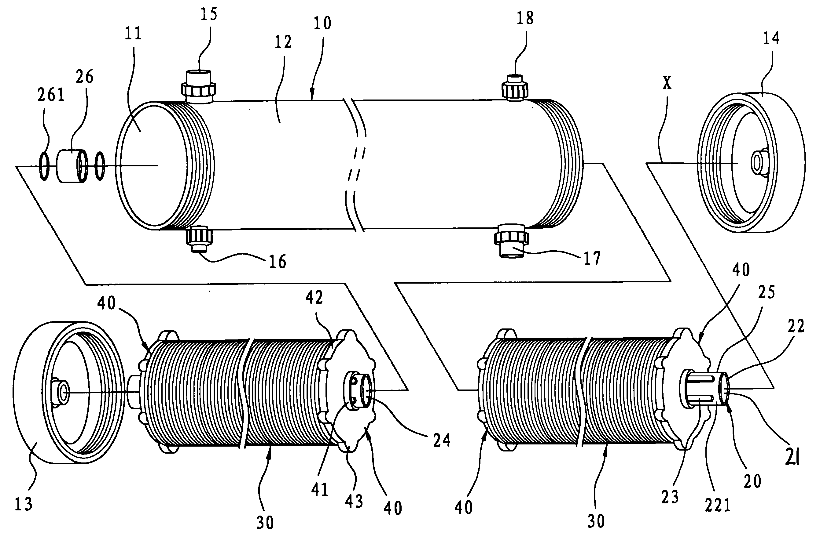
图1为本发明可快速清洁滤膜的水处理装置的第一实施例立体分解图;Fig. 1 is the three-dimensional exploded view of the first embodiment of the water treatment device that can quickly clean the filter membrane of the present invention;
图2为该第一实施例的局部分解立体图,说明过滤单元的各个元件组成结构关系;Fig. 2 is a partially exploded perspective view of the first embodiment, illustrating the composition and structural relationship of each element of the filter unit;
图3为该第一实施例的组合剖视图,其显示过滤单元与喷洗单元组装在壳体内的状态;Fig. 3 is a combined sectional view of the first embodiment, which shows the state in which the filter unit and the spray unit are assembled in the housing;
图4为该第一实施例的组合剖视图,其显示沿着图3中的I-I截面所剖切出的内部结构状态;Fig. 4 is the assembled sectional view of this first embodiment, and it shows the state of the internal structure cut along the I-I section among Fig. 3;
图5为该第一实施例的喷气管外观立体图;Fig. 5 is the perspective view of the appearance of the jet pipe of the first embodiment;
图6为本发明第二实施例的组合剖视图,说明一产水管是枢设在壳体内而可转;Fig. 6 is a combined cross-sectional view of the second embodiment of the present invention, illustrating that a water production pipe is pivotally installed in the casing to be rotatable;
图7为该第二实施例使用状态参考图,说明壳体内部的喷气管与产水管在同时作动状态下的喷洗情形;Fig. 7 is a reference diagram of the use state of the second embodiment, illustrating the spraying situation when the air injection pipe and the water production pipe inside the housing are in simultaneous operation;
图8为本发明第三实施例的组合剖视图,说明壳体为无端盖的开放式结构。Fig. 8 is a combined cross-sectional view of the third embodiment of the present invention, illustrating that the housing is an open structure without end caps.
图中:In the picture:
壳体 10 过滤室 11Shell 10
管壳 12 第一壳盖 13Shell 12
第二壳盖 14 进水孔 15
进气口 16 排水孔 17Air inlet 16
排气口 18 产水管 20
出水孔 21 管壁 22Outlet hole 21 Pipe wall 22
外周面 221 穿孔 23Perimeter 221 Perforation 23
第一管段 24 第二管段 25The
套接件 26 防水环圈 261
过滤单元 30 过滤膜袋 31
中央孔 32 导水盘 33Central hole 32 Drain
压板 34 导引盘 40
插接部 41 外周面 42
支撑部 43 容置槽 44Support part 43
喷洗单元 50 供气泵浦 51
喷气管 52 曝气口 53
产水管 60 减速马达 70
壳体 80 产水管 90
具体实施方式 Detailed ways
为了进一步解释本发明的技术方案,下面通过具体实施例来对本发明进行详细阐述。In order to further explain the technical solution of the present invention, the present invention will be described in detail below through specific examples.
参照图1及图3,本发明涉及的一种可快速清洁滤膜的水处理装置的第一实施例,包含有一壳体10、一产水管20、至少一过滤单元30、复数个导引盘40以及一喷洗单元50。Referring to Fig. 1 and Fig. 3, the first embodiment of a water treatment device that can quickly clean the filter membrane according to the present invention includes a
该壳体10,具有一沿着一水平轴线X延伸且可界定出一过滤室11的管壳12、分别组接在该管壳12两端的第一壳盖13与一第二壳盖14、对应该第一壳盖13且与该过滤室11连通的一进水孔15及一进气口16、对应该第二壳盖14且与过滤室11连通的一排水孔17及一排气口18,该进气口16可导接该喷洗单元50的供气泵浦51,以供高压气体泵送入该过滤室11内(下有详细说明)。The
该产水管20,是与该水平轴线X同轴向地装设在该壳体10内,具有一环绕该轴线且可界定出一出水孔21的管壁22、以及多数个自该管壁22的一外周面221朝内贯通该出水孔21的穿孔23,在本实施例中,该产水管20包括有一第一管段24、一与该第一管段24同轴的第二管段25,以及一接设在该第一、二管段24、25的间的套接件26,该套接件26是中空且两端呈开放状,其内壁面上并嵌设有防水环圈261。The
参照图1至图3,在本实施例中共设有二过滤单元30,且分别可拆卸地层迭套设在该产水管20的第一管段24和第二管段25外周面上,每个过滤单元30都具有复数个碟片状的过滤膜袋31、一位于过滤膜袋31中央且恰与该等穿孔23形成连通的中央孔32,以及复数个以两两为一组用以将邻接的过滤膜袋31相互嵌接的导水盘33,此外,前述过滤单元30的过滤膜袋31是呈垂直于该产水管20轴向的水平排列方式,并且是分别利用压置在第一管段24和第二管段25端部上的两个压板34以获得定位,而有关前述过滤膜袋31与导水盘33的详细结构与功能,均与本案发明人名下中国第ZL200510132492.0号发明专利相同,且因为过滤膜袋31与导水盘33并非本发明重点,故此不再多加赘述。Referring to Fig. 1 to Fig. 3, there are two
前述的导引盘40,是以两两为一组而分别套设在该产水管20的第一管段24和第二管段25端部上,每一个导引盘40分别具有一自中央沿轴向凸伸的插接部41,以及复数个自一外周面42沿径向朝外凸伸的支撑部43,而相邻的支撑部43之间恰形成一凹陷状的容置槽44,在本实施例中,该插接部41恰可供该套接件26插置于其内,使该产水管20的第一管段24与第二管段25连结为一体,而前述支撑部43则可抵触在该壳体10的内周面,用以使两组过滤单元30在壳体10内保持同轴向,并且便利于两组过滤单元30的组立对位。The above-mentioned
该喷洗单元50,参照图3及图5,具有一与该进气口16导接的供气泵浦51、一自该进气口16延伸入该壳体10内且贴设在管壳12内周面上的的喷气管52以及复数个自该喷气管52的径向朝外开通的曝气口53,并且使得前述曝气口53恰对应前述过滤单元30的过滤膜袋31,而喷气管52的管径是小于导引盘40的容置槽44宽度,以便于将套有导引盘40的过滤单元30推移入该过滤室11内。The
使用时,参照图3及图4,操作者便可先驱动外界干净的水液至产水管20,以进行一逆洗程序(这时的进水孔是呈关闭状态),当大量水液充满整个过滤膜袋31,在水压的泵送下,便可使整个过滤膜袋31呈鼓起状,进而反向推挤堵塞在膜孔的杂质,然后,排水孔17的阀门开启,使过滤室11内少量的逆洗水(约5~10%)由该排水口17排出过滤室11外,同时,原本鼓起的过滤膜袋31会因过滤室11内的水压降低而逐渐内缩回原状,使每个过滤膜袋31的间仍保持适当的间距,接着关闭该排水孔17,然后启动该供气泵浦51,这时高压空气便经由该喷气管52的曝气口53打入该过滤室11内,以冲击清洁过滤膜袋31的表面,而且,这些高压空气在喷击过滤单元30的过滤膜袋31时,会受到膜面的分流、阻滞,并在碰到壳体10周壁而反向冲激流动,如此,在高速的反复振荡下,会使得过滤室11内涌现大量且细微的扰动气泡,降低污水中的杂质、污泥积附在过滤膜袋31孔隙的机率,在运转预定时间后,再将供气泵浦51停机,接着,打开该排水孔17,将过滤室11内的全部逆洗水液排出壳体10外,如此,即可快速完成清洁逆洗的作业。When in use, referring to Fig. 3 and Fig. 4, the operator can first drive the clean water from the outside to the water production pipe 20 to perform a backwash procedure (at this time, the water inlet is closed), when a large amount of water is full The entire filter membrane bag 31, under the pumping of water pressure, can make the whole filter membrane bag 31 bulge, and then reversely push the impurities blocked in the membrane holes, and then, the valve of the drain hole 17 is opened to filter A small amount of backwash water (about 5-10%) in the chamber 11 is discharged out of the filter chamber 11 through the outlet 17, and at the same time, the originally bulging filter membrane bag 31 will gradually shrink inward due to the decrease in water pressure in the filter chamber 11 Get back to the original state, make each filter membrane bag 31 still keep an appropriate distance, then close the drainage hole 17, then start the air supply pump 51, at this moment the high-pressure air is just blown through the aeration port 53 of the jet pipe 52 into the filter chamber 11 to impact and clean the surface of the filter membrane bag 31, and when the high-pressure air hits the filter membrane bag 31 of the filter unit 30, it will be shunted and blocked by the membrane surface, and when it hits the shell 10 surrounding walls of the body and the reverse impulse flow, so, under the high-speed repeated oscillation, a large number of fine disturbing bubbles will emerge in the filter chamber 11, reducing the impurity and sludge in the sewage accumulating in the pores of the filter membrane bag 31 Probability, after running for a predetermined time, stop the air supply pump 51, then open the drain hole 17, and discharge all the backwash water in the filter chamber 11 out of the housing 10, so that the cleaning backwash can be quickly completed Washing job.
再如图6,其为本发明的第二实施例,在本实施例中,该产水管60是设置成穿枢在该壳体10中央,且该产水管30一端以传动元件(如链条)连结一减速马达70,而该等导引盘40的支撑部则设置成不接触该喷气管52,以防止两者产生干涉,如此,在减速马达70的驱动的下,便可使该产水管产生旋动,以同步驱使过滤膜袋产生旋转,如图7,同时配合供气泵浦50对过滤室11内所施加的扰动气泡,使整个过滤单元30在360度皆可完全的受到气体的喷洗冲除,更可发挥本发明的快速清洁优点。As shown in Figure 6 again, it is the second embodiment of the present invention. In this embodiment, the
值得一提的是,上述第二实施例亦可使用在MBR(MembraneBio-Reactor,薄膜生物反应器)上,以防止生物膜累积过厚而阻塞,并可调节好氧区与厌氧区的比例,以改变污水中的浓度极化现象。It is worth mentioning that the above-mentioned second embodiment can also be used in MBR (Membrane Bio-Reactor, thin film bioreactor), to prevent the biofilm from accumulating too thick and blocking, and can adjust the ratio of aerobic zone to anaerobic zone , to change the concentration polarization phenomenon in sewage.
又如图8,其为本发明的第三实施例,在此实施例中,该壳体80的两侧成开放状,且整个壳体10、产水管90与过滤单元30是浸入一污水处理槽(图未示)内,产水管90是在外部以负压汲取壳体80中的水液,利用喷洗装置50的设置,亦可达成与第一实施例相同的功效。As shown in Fig. 8, it is the third embodiment of the present invention. In this embodiment, both sides of the
归纳上述,将本发明涉及的一种可快速清洁滤膜的水处理装置所能达成的优点归纳如下:To sum up the above, the advantages that can be achieved by a water treatment device that can quickly clean the filter membrane involved in the present invention are summarized as follows:
一、由于壳体10与过滤单元30采用卧式排列的结构,加上逆洗水只有少量排出壳体10外,如此,过滤膜袋31便可保持在垂立状态,加上所打入的高压气体可直接地对过滤膜袋31产生喷击、扰动,所以便可达到快速清洁膜面的作用,且水中的扰动气泡亦可降低膜面滤饼的生成。1. Since the
二、由于整个装置并未设有旋转盘,因此过滤单元30在进行逆洗时,高压气体不受到旋转盘的阻碍,可使整个过滤膜袋31完全受到喷洗冲除,降低膜面中央结垢的情形。2. Since the whole device is not equipped with a rotating disc, when the
三、而且过滤单元30在进行逆洗时,不必完全排除过滤室11内的水液,而是利用高压气体取代原有的喷洗水柱,因此水源及动力的损耗相当小,不仅经济且环保。3. Moreover, when the
惟以上所述者,仅为本发明的三个实施例而已,当不能以此限定本发明实施的范围,即大凡依本发明申请专利范围及发明说明内容所作的简单的等效变化与修饰,皆应仍属本发明专利涵盖的范围内。But the above are only three embodiments of the present invention, and the scope of the present invention cannot be limited with this, that is, all simple equivalent changes and modifications made according to the patent scope of the present invention and the description of the invention, All should still belong to the scope that the patent of the present invention covers.
Claims (6)
Priority Applications (1)
| Application Number | Priority Date | Filing Date | Title |
|---|---|---|---|
| CN200910225382A CN102060353B (en) | 2009-11-16 | 2009-11-16 | A water treatment device that can quickly clean the filter membrane |
Applications Claiming Priority (1)
| Application Number | Priority Date | Filing Date | Title |
|---|---|---|---|
| CN200910225382A CN102060353B (en) | 2009-11-16 | 2009-11-16 | A water treatment device that can quickly clean the filter membrane |
Publications (2)
| Publication Number | Publication Date |
|---|---|
| CN102060353A CN102060353A (en) | 2011-05-18 |
| CN102060353B true CN102060353B (en) | 2012-08-29 |
Family
ID=43995883
Family Applications (1)
| Application Number | Title | Priority Date | Filing Date |
|---|---|---|---|
| CN200910225382A Expired - Fee Related CN102060353B (en) | 2009-11-16 | 2009-11-16 | A water treatment device that can quickly clean the filter membrane |
Country Status (1)
| Country | Link |
|---|---|
| CN (1) | CN102060353B (en) |
Families Citing this family (5)
| Publication number | Priority date | Publication date | Assignee | Title |
|---|---|---|---|---|
| CN105268224B (en) * | 2014-07-01 | 2017-09-12 | 上海上阳流体科技有限公司 | Sewage treatment pot |
| CN105268232B (en) * | 2014-07-01 | 2017-08-29 | 上海上阳流体科技有限公司 | Cleaning device |
| CN108499365B (en) * | 2018-03-26 | 2020-12-01 | 徐州云创物业服务有限公司 | Automatic cleaning device for outer wall of water purification microporous filter membrane pipe |
| CN111992044B (en) * | 2020-09-11 | 2022-04-26 | 江苏坤奕环境技术股份有限公司 | Energy-saving ultrahigh-power concentration membrane module, membrane bag thereof, water treatment system and method |
| CN117776375B (en) * | 2024-01-31 | 2024-08-23 | 山东华实电气股份有限公司 | Sewage treatment separating mechanism |
Citations (3)
| Publication number | Priority date | Publication date | Assignee | Title |
|---|---|---|---|---|
| CN1868897A (en) * | 2005-05-24 | 2006-11-29 | 郭瑜珊 | Water treatment device for enhanced membrane cleaning |
| CN1990078A (en) * | 2005-12-26 | 2007-07-04 | 郭其昌 | Interlocking water guide dish set |
| EP1844833A1 (en) * | 2005-01-04 | 2007-10-17 | Salvador Ros Roca | Improved self-cleaning filter for agricultural irrigation water |
-
2009
- 2009-11-16 CN CN200910225382A patent/CN102060353B/en not_active Expired - Fee Related
Patent Citations (3)
| Publication number | Priority date | Publication date | Assignee | Title |
|---|---|---|---|---|
| EP1844833A1 (en) * | 2005-01-04 | 2007-10-17 | Salvador Ros Roca | Improved self-cleaning filter for agricultural irrigation water |
| CN1868897A (en) * | 2005-05-24 | 2006-11-29 | 郭瑜珊 | Water treatment device for enhanced membrane cleaning |
| CN1990078A (en) * | 2005-12-26 | 2007-07-04 | 郭其昌 | Interlocking water guide dish set |
Also Published As
| Publication number | Publication date |
|---|---|
| CN102060353A (en) | 2011-05-18 |
Similar Documents
| Publication | Publication Date | Title |
|---|---|---|
| CN102060353A (en) | Water treatment device capable of quickly cleaning filter membrane | |
| CN212417169U (en) | An environmentally friendly water treatment filter device | |
| CN101485944A (en) | Water filter special for water source heat pump system | |
| CN116236913B (en) | An ultrafiltration membrane device with circulating filtration function for domestic water | |
| CN209456196U (en) | A sewage treatment and purification device with deodorization function | |
| CN201263972Y (en) | Aeration inner pressure film filter | |
| CN210021307U (en) | Bubble backflushing type filter | |
| WO2025180263A1 (en) | New-type backwash filter water purifier | |
| TW201043325A (en) | Water treating device capable of rapidly cleaning filter membrane | |
| KR102124653B1 (en) | Screen equipped with membrane and media | |
| CN220831486U (en) | Fish just separator | |
| CN216170363U (en) | Intelligent flushing type water purifier | |
| CN212548525U (en) | Filter element with cleaning function for industrial production sewage filtration | |
| CN103482759B (en) | A kind of Novel immersed membrane bio-reactor assembly | |
| CN115108659A (en) | Filtering and backwashing device | |
| CN202113680U (en) | Sludge removing device of full-immersion rotary disc filter | |
| CN103239991B (en) | Self-cleaning fluid filtering device | |
| CN223760777U (en) | Disc type PM membrane filter difficult to block | |
| JP2011079100A (en) | Filter device | |
| JP3662301B2 (en) | Water absorption strainer for pump equipment | |
| TWI533916B (en) | Self - cleaning fluid filter | |
| CN217773403U (en) | Circulating water secondary filter screen | |
| CN219950680U (en) | Be applied to wheeled MBR structure of sewage treatment | |
| CN111892196A (en) | Combined type filter with air entrainment function and have its filtration system | |
| CN213112635U (en) | A high-efficiency water-saving reverse osmosis water purification equipment |
Legal Events
| Date | Code | Title | Description |
|---|---|---|---|
| C06 | Publication | ||
| PB01 | Publication | ||
| C10 | Entry into substantive examination | ||
| SE01 | Entry into force of request for substantive examination | ||
| C14 | Grant of patent or utility model | ||
| GR01 | Patent grant | ||
| CF01 | Termination of patent right due to non-payment of annual fee |
Granted publication date: 20120829 Termination date: 20191116 |
|
| CF01 | Termination of patent right due to non-payment of annual fee |