CN102054633B - Shunt tripping device with auxiliary contacts - Google Patents

Shunt tripping device with auxiliary contacts Download PDF

Info

Publication number
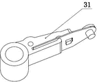
CN102054633B
CN102054633B CN 201010565678 CN201010565678A CN102054633B CN 102054633 B CN102054633 B CN 102054633B CN 201010565678 CN201010565678 CN 201010565678 CN 201010565678 A CN201010565678 A CN 201010565678A CN 102054633 B CN102054633 B CN 102054633B
Authority
CN
China
Prior art keywords
contact
unit
housing
auxiliary contact
moving
Prior art date
Legal status (The legal status is an assumption and is not a legal conclusion. Google has not performed a legal analysis and makes no representation as to the accuracy of the status listed.)
Active
Application number
CN 201010565678
Other languages
Chinese (zh)
Other versions
CN102054633A (en
Inventor
许利战
孙再胜
祁卫华
Current Assignee (The listed assignees may be inaccurate. Google has not performed a legal analysis and makes no representation or warranty as to the accuracy of the list.)
Delixi Electric Co Ltd
Original Assignee
Delixi Electric (Ningbo) Co Ltd
Priority date (The priority date is an assumption and is not a legal conclusion. Google has not performed a legal analysis and makes no representation as to the accuracy of the date listed.)
Filing date
Publication date
Application filed by Delixi Electric (Ningbo) Co Ltd filed Critical Delixi Electric (Ningbo) Co Ltd
Priority to CN 201010565678 priority Critical patent/CN102054633B/en
Publication of CN102054633A publication Critical patent/CN102054633A/en
Application granted granted Critical
Publication of CN102054633B publication Critical patent/CN102054633B/en
Active legal-status Critical Current
Anticipated expiration legal-status Critical

Links

Images

Landscapes

  • Breakers (AREA)

Abstract

The invention relates to a shunt tripping device with auxiliary contacts, in particular to the shunt tripping device in which a group of auxiliary contacts are arranged in the shell of the shunt tripping device, and a power supply of the auxiliary contacts is different from that of a shunt tripping coil of the shunt tripping device. The shunt tripping device with the auxiliary contacts adopts thefollowing technical scheme that: the shunt tripping device with the auxiliary contacts comprises the shell, a shunt stripping unit and an auxiliary contact unit arranged in the shell, wherein the shunt tripping unit comprises a handle, a tripping mechanism and a contact mechanism. The shunt tripping device with the auxiliary contacts is characterized in that: the power supply of the auxiliary contact unit is independent of the power supply used by a coil of the shunt tripping unit. By adopting the scheme, the shunt tripping device with the auxiliary contacts overcomes the disadvantages in theprior art; and the shunt tripping device in which a group of auxiliary contacts are arranged in the shell of the shunt tripping device, and the power supply of the auxiliary contacts is different from the power supply used by the coil of the shunt tripping unit is provided.

Description

A kind of shunt release with auxiliary contact
Technical field
The present invention relates to a kind of shunt release, refer to especially in the housing of shunt release, be provided with one group of auxiliary contact, and the power supply of the auxiliary contact shunt release different from the power supply of the shunt opening trip coil of shunt release.
Background technology
Shunt release on the existing market has two kinds, a kind of is the shunt release of function singleness, its inside only only has the shunted exciter tripping unit, another kind also is provided with one group of auxiliary contact unit except the shunted exciter tripping unit is set in the plastic casing of 18mm, but the coil of this auxiliary contact unit and shunted exciter tripping unit shares an end points, therefore, this auxiliary contact unit must use with the coil of shunted exciter tripping unit same power supply, otherwise the shunted exciter tripping unit can't work.When if the coil of customer requirement auxiliary contact unit and shunted exciter tripping unit uses different electrical power, must be on shunt release next door independent auxiliary contact of assembly unit again, so both increase cost, taken again the space of user's distribution board, also increased the difficulty of user's assembly unit.
Summary of the invention
The present invention overcomes the deficiency that prior art exists, and provide a kind of and in the housing of shunt release, be provided with one group of auxiliary contact, and the power supply of the auxiliary contact novel shunt release different from the power supply of the coil use of shunted exciter tripping unit.
Realize above-mentioned purpose, the present invention adopts following technical scheme, a kind of shunt release with auxiliary contact, include housing, be arranged on shunted exciter tripping unit and auxiliary contact unit in the housing, the shunted exciter tripping unit includes handle, tripping mechanism and contact mechanism, it is characterized in that: the power supply that the power supply of described auxiliary contact unit coil independent and the shunted exciter tripping unit uses.
By adopting such scheme, we are provided with one group of auxiliary contact unit in housing, and the power supply that this auxiliary contact unit uses is different from the power supply that the coil of shunted exciter tripping unit uses, can under different voltage, use this shunt release like this, bring a lot of convenience for user's use, type selecting.
The further setting of the present invention is: described auxiliary contact unit includes moving contact, two groups of fixed contacts, pull bar and pivoted arms, described two groups of fixed contact fixed cards are connected in the housing, described two groups of fixed contacts are for disconnecting fixed contact and conducting fixed contact, described pivoted arm one end is fixedly installed on the contact of shunted exciter tripping unit and supports, the other end is connected with moving contact by connector, moving contact switches mutually with rotation and two fixed contacts of pivoted arm, be provided with fixture block on the described housing, the fixed contact of auxiliary contact unit is fastened on the housing by fixture block.
By adopting such scheme, more reasonable when the control moving contact turns to disconnection fixed contact and conducting fixed contact, make moving contact consist of auxiliary contact with the cooperation of two fixed contacts and become often to open or normally off.
Of the present invention further the setting again is: an end of described pull bar is fixedly installed boss, the hinged moving block that is provided with on the other end, described moving block rotates and is arranged on the housing, be provided with back-moving spring between moving block and the housing, moving block its other end with respect to hinged end under the drive of pull bar becomes to compress cooperation with the yoke of shunted exciter tripping unit, and the lug boss position with respect to pull bar on the described housing is provided with through hole.
Adopt such scheme, can be when shunt release and circuit breaker be used in conjunction with, connecting rod penetrates through hole and cooperates with the boss of pull bar, like this circuit breaker when disconnection, connecting rod drive pull bar, pull bar spurs moving block, and auxiliary contact is also disconnected.
Below in conjunction with accompanying drawing the embodiment of the invention is further described.
Description of drawings
Fig. 1 is the structural representation of embodiment of the invention shunted exciter tripping unit and auxiliary contact unit off-state;
Fig. 2 is pivoted arm and the contact supporting structure schematic diagram among Fig. 1;
Fig. 3 is the structural representation of the pull bar among Fig. 1;
Fig. 4 is the structural representation of the moving contact among Fig. 1;
Fig. 5 is the structural representation of embodiment of the invention shunted exciter tripping unit and auxiliary contact unit "on" position;
Fig. 6 is the moving contact of auxiliary contact unit and the syndeton schematic diagram of pivoted arm;
Fig. 7 is the syndeton schematic diagram of connecting rod and housing.
Embodiment
Such as Fig. 1---shown in Figure 7, a kind of shunt release with auxiliary contact, include housing 1, be arranged on shunted exciter tripping unit 2 and auxiliary contact unit 3 in the housing 1, shunted exciter tripping unit 2 includes handle 21, tripping mechanism and contact mechanism, in embodiments of the present invention, the power supply that uses of the power supply of described auxiliary contact unit 3 coil independent and shunted exciter tripping unit 2.Adopt such scheme, we are provided with one group of auxiliary contact unit 3 in housing 1, and the power supply that this auxiliary contact unit 3 uses is different from the power supply that the coil of shunted exciter tripping unit 2 uses, can under different voltage, use this shunt release like this, bring a lot of convenience for user's use, type selecting.
In embodiments of the present invention, described auxiliary contact unit 3 includes moving contact 31, two groups of fixed contacts 32, pull bar 33 and pivoted arm 34, described moving contact 31 is hinged on the housing 1, described two groups of fixed contact 32 fixed cards are connected in the housing 1, described two groups of fixed contacts 32 are for disconnecting fixed contact and conducting fixed contact, one end of described pull bar 33 is fixedly installed boss 331, the hinged moving block 332 that is provided with on the other end, described moving block 332 rotates and is arranged on the housing 1, be provided with back-moving spring 334 between moving block 332 and the housing 1, it compresses cooperation with respect to 22 one-tenth of the yokes of the other end 3321 of hinged end and shunted exciter tripping unit to moving block 332 under the drive of pull bar 33, boss 331 positions with respect to pull bar 33 on the described housing 1 are provided with through hole, like this when shunt release and circuit breaker are used in conjunction with, connecting rod can penetrate through hole and cooperate with the boss 331 of pull bar 33, when circuit breaker disconnects, connecting rod drives pull bar 33, pull bar 33 pulling moving blocks 332 finally make auxiliary contact also disconnect; One end of described pivoted arm 34 is fixedly installed on the contact of shunted exciter tripping unit 2 and supports on 23, the other end is connected with moving contact 31 by connector 341, pull like this handle 21, thereby pivoted arm 34 also rotated simultaneously and drives moving contact 31 and switches between two fixed contacts 31 when contact supported 23 to rotate, and main purpose is auxiliary contact unit and the disconnection of shunted exciter tripping units synchronization or combined floodgate.More reasonable when control moving contact 31 turns to disconnection fixed contact and conducting fixed contact in the such scheme, make moving contact 31 consist of auxiliary contact with the cooperation of two fixed contacts 32 and become often to open or normally off.In embodiments of the present invention, be provided with fixture block 11 on the described housing 1, the fixed contact 32 of auxiliary contact unit is fastened on the housing 1 by fixture block 11.
Shunt release with auxiliary contact of the present invention only illustrates preferred embodiment in this is above-mentioned; be not to its restriction; this professional and technical personnel according to the present invention inventive concept and spirit can structurally make various variations or modification, so these must belong to protection scope of the present invention.

Claims (2)

1. shunt release with auxiliary contact, include housing, be arranged on shunted exciter tripping unit and auxiliary contact unit in the housing, the shunted exciter tripping unit includes handle, tripping mechanism and contact mechanism, it is characterized in that: the power supply of described auxiliary contact unit is independent of the power supply of the coil use of shunted exciter tripping unit, described auxiliary contact unit includes moving contact, two groups of fixed contacts, pull bar and pivoted arm, described two groups of fixed contact fixed cards are connected in the housing, described two groups of fixed contacts are for disconnecting fixed contact and conducting fixed contact, described pivoted arm one end is fixedly installed on the contact of shunted exciter tripping unit and supports, the other end is connected with moving contact by connector, moving contact switches mutually with rotation and two fixed contacts of pivoted arm, be provided with fixture block on the described housing, the fixed contact of auxiliary contact unit is fastened on the housing by fixture block.
2. the shunt release with auxiliary contact according to claim 1, it is characterized in that: an end of described pull bar is fixedly installed boss, the hinged moving block that is provided with on the other end, described moving block rotates and is arranged on the housing, be provided with back-moving spring between moving block and the housing, moving block its other end with respect to hinged end under the drive of pull bar becomes to compress cooperation with the yoke of shunted exciter tripping unit, and the lug boss position with respect to pull bar on the described housing is provided with through hole.
CN 201010565678 2010-11-30 2010-11-30 Shunt tripping device with auxiliary contacts Active CN102054633B (en)

Priority Applications (1)

Application Number Priority Date Filing Date Title
CN 201010565678 CN102054633B (en) 2010-11-30 2010-11-30 Shunt tripping device with auxiliary contacts

Applications Claiming Priority (1)

Application Number Priority Date Filing Date Title
CN 201010565678 CN102054633B (en) 2010-11-30 2010-11-30 Shunt tripping device with auxiliary contacts

Publications (2)

Publication Number Publication Date
CN102054633A CN102054633A (en) 2011-05-11
CN102054633B true CN102054633B (en) 2013-10-23

Family

ID=43958839

Family Applications (1)

Application Number Title Priority Date Filing Date
CN 201010565678 Active CN102054633B (en) 2010-11-30 2010-11-30 Shunt tripping device with auxiliary contacts

Country Status (1)

Country Link
CN (1) CN102054633B (en)

Families Citing this family (2)

* Cited by examiner, † Cited by third party
Publication number Priority date Publication date Assignee Title
CN105702488B (en) * 2016-03-30 2018-03-27 上海电科电器科技有限公司 The internal feedback device of control and protective switching device
CN116387108B (en) * 2023-04-06 2026-01-13 浙江厚达电气有限公司 Better circuit breaker auxiliary device of withstand voltage performance

Citations (5)

* Cited by examiner, † Cited by third party
Publication number Priority date Publication date Assignee Title
US4742321A (en) * 1987-06-25 1988-05-03 General Electric Company Molded case circuit breaker with accessory functions
US4907342A (en) * 1989-01-18 1990-03-13 General Electric Company Method of assembling a molded case circuit breaker current transformer assembly
CN101226857A (en) * 2007-11-27 2008-07-23 Tcl低压电器(无锡)有限公司 Shunt release with indicated function
CN201576639U (en) * 2009-11-30 2010-09-08 上海永继电气有限公司 Multifunctional breaker accessory
CN201868357U (en) * 2010-11-30 2011-06-15 德力西电气(宁波)有限公司 Shunt tripping device with auxiliary contacts

Patent Citations (5)

* Cited by examiner, † Cited by third party
Publication number Priority date Publication date Assignee Title
US4742321A (en) * 1987-06-25 1988-05-03 General Electric Company Molded case circuit breaker with accessory functions
US4907342A (en) * 1989-01-18 1990-03-13 General Electric Company Method of assembling a molded case circuit breaker current transformer assembly
CN101226857A (en) * 2007-11-27 2008-07-23 Tcl低压电器(无锡)有限公司 Shunt release with indicated function
CN201576639U (en) * 2009-11-30 2010-09-08 上海永继电气有限公司 Multifunctional breaker accessory
CN201868357U (en) * 2010-11-30 2011-06-15 德力西电气(宁波)有限公司 Shunt tripping device with auxiliary contacts

Non-Patent Citations (2)

* Cited by examiner, † Cited by third party
Title
冯关水.智能型万能式断路器的选型与应用.《电气应用》.2007,(第12期),第79-83页.
智能型万能式断路器的选型与应用;冯关水;《电气应用》;20071231(第12期);第79-83页 *

Also Published As

Publication number Publication date
CN102054633A (en) 2011-05-11

Similar Documents

Publication Publication Date Title
CN201868357U (en) Shunt tripping device with auxiliary contacts
CN204632700U (en) The tripping system of residual current circuit breaker
CN104183434B (en) A kind of residual current circuit breaker with reverse wiring structure
CN102915890B (en) Crow plate trip circuit breaker
CN102054633A (en) Shunt tripping device with auxiliary contacts
CN203983204U (en) A kind of residual current circuit breaker with reverse wiring structure
CN103681124A (en) Sealed multi-electrode circuit breaker
CN110993414A (en) A smart home bluetooth controlled mechanical knife switch
CN202307740U (en) Switch device for temperature control
CN202977980U (en) Switch cabinet
CN102882269A (en) Novel change-over switch
CN202616152U (en) An operating mechanism of a miniature circuit breaker
AU2008207285B2 (en) Switched arrangement
CN210443513U (en) Plastic case leakage circuit breaker
CN202977979U (en) Switch cabinet
CN209843646U (en) Circuit breakers with overvoltage and undervoltage protection components
CN203386628U (en) Air switch interlocking structure
CN202307752U (en) Electricity leakage protection device and circuit breaker
CN202058674U (en) Trip gear for plastic casing breaker
CN202183343U (en) Device capable of avoiding tripping during overload alarm of breaker
CN201478229U (en) Intelligent breaker with plastic shell
CN206961781U (en) A kind of moving contact component and the miniature circuit breaker including the moving contact component
CN207947243U (en) A kind of control and protective switching device
CN223977629U (en) Three-phase power supply positive and negative phase sequence change-over switch for teaching
CN203070960U (en) Power sampling circuit device for automatic transfer switch

Legal Events

Date Code Title Description
C06 Publication
PB01 Publication
C10 Entry into substantive examination
SE01 Entry into force of request for substantive examination
C14 Grant of patent or utility model
GR01 Patent grant
ASS Succession or assignment of patent right

Owner name: DELIXI GROUP

Free format text: FORMER OWNER: DELIXI ELECTRICAL (NINGBO) CO., LTD.

Effective date: 20141104

C41 Transfer of patent application or patent right or utility model
COR Change of bibliographic data

Free format text: CORRECT: ADDRESS; FROM: 315000 NINGBO, ZHEJIANG PROVINCE TO: 325000 WENZHOU, ZHEJIANG PROVINCE

TR01 Transfer of patent right

Effective date of registration: 20141104

Address after: Liushi Delixi High-tech Industrial Park Yueqing City 325000 Zhejiang city of Wenzhou Province

Patentee after: Delixi Electric Co., Ltd.

Address before: 315000 No. 1958 Jiangnan Road, hi tech Zone, Zhejiang, Ningbo

Patentee before: Delixi Electric (Ningbo) Co., Ltd.