CN102032280A - Damping coupling - Google Patents
Damping coupling Download PDFInfo
- Publication number
- CN102032280A CN102032280A CN2010106045135A CN201010604513A CN102032280A CN 102032280 A CN102032280 A CN 102032280A CN 2010106045135 A CN2010106045135 A CN 2010106045135A CN 201010604513 A CN201010604513 A CN 201010604513A CN 102032280 A CN102032280 A CN 102032280A
- Authority
- CN
- China
- Prior art keywords
- damping
- hub
- disc
- washer
- flange
- Prior art date
- Legal status (The legal status is an assumption and is not a legal conclusion. Google has not performed a legal analysis and makes no representation as to the accuracy of the status listed.)
- Granted
Links
Images

Landscapes
- Mechanical Operated Clutches (AREA)
Abstract
Description
技术领域technical field
本发明涉及汽车技术领域,具体地讲,是一种用在电动汽车上的减振联轴器,用于电动机与变速器之间的联接。The invention relates to the technical field of automobiles, in particular to a vibration-damping coupling used in electric automobiles, which is used for coupling between electric motors and transmissions.
背景技术Background technique
电动汽车的电动机与变速器之间的联接,一般采用刚性联轴器,因其不需要换挡,不存在换档所带来的冲击振动,传动系统的振动对电动机的影响也不太明显。随着电动汽车理论的日渐丰富,变速器被自动换档的两档或多档变速器取代,而换档不可避免地产生冲击,而刚性联轴器无法吸收电动机和变速器之间的工作时产生的振动冲击;再则,传动系统本身的振动也会对电动机产生不利影响,也会降低电动机及传动系统零部件的可靠性和寿命。由于电动车的结构紧凑,各种型式的普通弹性联轴器因可靠性及轴向、径向尺寸等问题也不能直接选用。因此,需要重新设计一种具有减振功能的联轴器,来有效地改善所联接两轴之间的冲击,传递运动和转矩。The connection between the electric motor and the transmission of an electric vehicle generally adopts a rigid coupling, because it does not need to shift gears, there is no impact vibration caused by shifting, and the vibration of the transmission system has less obvious influence on the motor. With the increasingly rich theory of electric vehicles, the transmission is replaced by a two-speed or multi-speed transmission with automatic shifting, and the shifting inevitably produces shocks, and the rigid coupling cannot absorb the vibration generated during work between the electric motor and the transmission Impact; moreover, the vibration of the transmission system itself will also have an adverse effect on the motor, and will also reduce the reliability and life of the motor and transmission system components. Due to the compact structure of electric vehicles, various types of ordinary elastic couplings cannot be directly selected due to problems such as reliability and axial and radial dimensions. Therefore, it is necessary to redesign a coupling with a damping function to effectively improve the impact between the connected two shafts and transmit motion and torque.
发明内容Contents of the invention
本发明的目的在于提供一种结构紧凑的减振联轴器,能有效地消减变速器换档冲击,减少传动系统振动对电动机的不利影响,提高电动机和传动系统零部件的可靠性及寿命。The purpose of the present invention is to provide a compact vibration damping coupling, which can effectively reduce the shifting impact of the transmission, reduce the adverse effect of transmission system vibration on the motor, and improve the reliability and life of the motor and transmission system components.
为解决以上技术问题,本发明所提供的一种减振联轴器,减振联轴器,包括法兰盘(1)、从动片(2)、盘毂(3)、减振盘(4)和减振弹簧(5),关键在于:所述法兰盘(1)的右端向外延伸成一敞口(1a),所述敞口(1a)外缘带有与法兰盘(1)轴线垂直的外翻边(1b),所述法兰盘(1)的外翻边(1b)与从动片(2)通过在圆周上均匀分布的第一铆钉(9)连接;所述盘毂(3)由盘毂幅板(3a)和盘毂芯(3b)构成,所述盘毂幅板(3a)左侧的盘毂芯(3b)上套装有第一阻尼垫圈(6),所述第一阻尼垫圈(6)呈T形且左端外径小于右端外径,所述从动片(2)套装在所述第一阻尼垫圈(6)左端外圆周上且该从动片(2)的右端面压在第一阻尼垫圈(6)的台阶上;所述盘毂幅板(3a)右侧的盘毂芯(3b)上从左到右依次套装有第二阻尼垫圈(7)、定位垫圈(10)、蝶形弹簧(8)和减振盘(4);所述从动片(2)、盘毂幅板(3a)与减振盘(4)在圆周方向上开有位置对应的长条孔,所述减振弹簧(5)安装在所述长条孔内,所述从动片(2)、盘毂(3)和减振盘(4)三者之间通过圆周上均匀分布的第二铆钉(11)连接,所述盘毂(3)能相对从动片(2)和减振盘(4)转动角度α,且-14°≤α≤14°。In order to solve the above technical problems, the present invention provides a vibration damping coupling, a vibration damping coupling, including a flange (1), a driven piece (2), a hub (3), a vibration damping disc ( 4) and damping spring (5), the key is: the right end of the flange (1) extends outwards to form an opening (1a), and the outer edge of the opening (1a) has a ) the outer flange (1b) perpendicular to the axis, the outer flange (1b) of the flange (1) is connected with the driven plate (2) through the first rivets (9) evenly distributed on the circumference; the The hub (3) is composed of a hub web (3a) and a hub core (3b), the hub core (3b) on the left side of the hub web (3a) is fitted with a first damping washer (6) , the first damping washer (6) is T-shaped and the outer diameter of the left end is smaller than the outer diameter of the right end, the driven piece (2) is sleeved on the outer circumference of the left end of the first damping washer (6) and the driven piece The right end face of (2) is pressed on the step of the first damping washer (6); the hub core (3b) on the right side of the hub web (3a) is sequentially fitted with the second damping washer ( 7), positioning washer (10), butterfly spring (8) and damping disc (4); the driven piece (2), hub web (3a) and damping disc (4) are in the circumferential direction There are elongated holes corresponding to the position, the damping spring (5) is installed in the elongated hole, and the driven plate (2), disc hub (3) and damping disc (4) are connected by second rivets (11) evenly distributed on the circumference, and the hub (3) can be rotated by an angle α relative to the driven plate (2) and the damping disc (4), and -14°≤α≤14° .
采用以上技术方案,法兰盘套装在驱动电动机的输出轴上,盘毂套装在变速器的输入轴上,电动机与变速器之间通过本发明连接在一起。当电动机运转时,电动机的输出轴带动法兰盘同步转动,法兰盘带动与其铆接在一起的从动片一起转动,由于盘毂能相对从动片和减振盘转动一定的角度,从动片压迫减振弹簧,使减振弹簧推动盘毂转动,将动力传递给盘毂,最终传递输出到变速器上。从动片快速转动的冲击载荷由减震弹簧吸收,减振弹簧起到了缓冲转动冲击及避免扭转振动产生共振的作用;盘毂幅板右侧设置的定位垫圈对阻尼垫圈进行压紧定位,蝶形弹簧可调整阻尼垫圈的阻尼值,使产品的阻尼均匀稳定。With the above technical solution, the flange is set on the output shaft of the drive motor, the disc hub is set on the input shaft of the transmission, and the motor and the transmission are connected together through the present invention. When the motor is running, the output shaft of the motor drives the flange to rotate synchronously, and the flange drives the driven plate that is riveted together with it to rotate together. Since the hub can rotate at a certain angle relative to the driven plate and the damping plate, the driven The plate compresses the damping spring, so that the damping spring pushes the disc hub to rotate, transmits the power to the disc hub, and finally transmits the power to the transmission. The impact load of the fast rotation of the driven plate is absorbed by the shock absorbing spring, which plays a role in buffering the rotating impact and avoiding resonance caused by torsional vibration; the positioning washer set on the right side of the disc hub plate compresses and positions the damping washer, and the butterfly The spring can adjust the damping value of the damping washer, so that the damping of the product is uniform and stable.
上述定位垫圈(10)的右端面设置有四个按圆周均匀分布的凸块(10a),所述凸块(10a)沿定位垫圈(10)的轴线延伸,该凸块(10a)穿过蝶形弹簧(8)的内孔并从减振盘(4)中伸出。The right end surface of the above-mentioned positioning washer (10) is provided with four protrusions (10a) uniformly distributed on the circumference, and the protrusions (10a) extend along the axis of the positioning washer (10), and the protrusions (10a) pass through the butterfly The inner hole of the shaped spring (8) and stretches out from the damping disc (4).
上述从动片(2)长条孔的外侧长边朝着与盘毂幅板(3a)相反的方向向外翻边成第一限位壁(2a),所述减振盘(4)长条孔的外侧长边也朝着与盘毂幅板(3a)相反的方向向外翻边成第二限位壁(4a),所述第一限位壁(2a)和第二限位壁(4a)构成“八”字形。The outer long side of the elongated hole of the driven piece (2) is flanged outwards in the direction opposite to the disc hub web (3a) to form the first limiting wall (2a), and the vibration damping disc (4) is long The outer long side of the bar hole is also turned outwards in the direction opposite to the hub web (3a) to form a second limiting wall (4a), the first limiting wall (2a) and the second limiting wall (4a) form the "eight" shape.
为了方便加工制造,上述盘毂幅板(3a)外圆周上开有供第二铆钉(11)通过的弧形长缺口(3c),从动片(2)和减振盘(4)上开有供第二铆钉(11)通过的圆孔。In order to facilitate processing and manufacturing, there is an arc-shaped long notch (3c) on the outer circumference of the above-mentioned hub web (3a) for the second rivet (11) to pass through. There is a circular hole for the passage of the second rivet (11).
上述法兰盘(1)的内孔为平键孔,所述盘毂(3)的内孔为花键孔。法兰盘通过平键孔套装在驱动电动机的输出轴上,盘毂通过花键孔套装在变速器的输入轴上。The inner hole of the flange (1) is a flat key hole, and the inner hole of the disc hub (3) is a spline hole. The flange is set on the output shaft of the driving motor through the flat key hole, and the disc hub is set on the input shaft of the transmission through the spline hole.
本发明的有益效果:Beneficial effects of the present invention:
1)将盘毂设计成盘毂幅板和盘毂芯两部分,增大了减振弹簧的设计空间,可安装大刚度强韧性的减振弹簧,使产品在使用过程中起步更平顺,避免减振压缩变形、断裂损坏现象,以延长减振弹簧的使用寿命。1) The disc hub is designed into two parts, the disc hub plate and the disc hub core, which increases the design space of the damping spring, and can install a damping spring with high stiffness and toughness to make the product start more smoothly during use and avoid Damping compression deformation, fracture damage phenomenon, in order to prolong the service life of the damping spring.
2)阻尼垫圈,增加了摩擦面积,磨损系数稳定,减振盘采用蝶形弹簧的变形原理对轴向零件的磨损间隙进行补偿,保证了阻尼更稳定,性能更优越。。2) The damping washer increases the friction area and the wear coefficient is stable. The vibration damping plate uses the deformation principle of the butterfly spring to compensate the wear gap of the axial parts, ensuring more stable damping and superior performance. .
综上所述,本发明利用离合器的工作原理进行巧妙构思,其结构简单可靠,能有效吸收电动机与变速器之间工作时产生的振动能量,减小电动汽车起动、制动、急加速、急减速等工况中的振动,避免因冲击对传动系统和电动机产生不利影响,减振性能优越,提高了整车的舒适性。In summary, the present invention utilizes the working principle of the clutch to carry out ingenious conception, and its structure is simple and reliable, which can effectively absorb the vibration energy generated during the operation between the motor and the transmission, and reduce the starting, braking, rapid acceleration, and rapid deceleration of electric vehicles. The vibration in other working conditions can avoid the adverse impact on the transmission system and the motor due to the impact, and the vibration damping performance is excellent, which improves the comfort of the vehicle.
附图说明Description of drawings
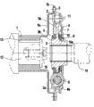
图1 是本发明结构示意图。Fig. 1 is a structural representation of the present invention.
图2 是图1中A-A剖视图。Fig. 2 is A-A sectional view among Fig. 1.
图中:1为法兰盘、2为从动片、3为盘毂、4为减振盘、5为减振弹簧、6为第一阻尼垫圈、7为第二阻尼垫圈、8为蝶形弹簧、9为第一铆钉、10 为定位垫圈、11为第二铆钉、12为电动机输出轴、13为平键、14为变速器输入轴。In the figure: 1 is the flange, 2 is the driven plate, 3 is the hub, 4 is the damping plate, 5 is the damping spring, 6 is the first damping washer, 7 is the second damping washer, 8 is the butterfly Spring, 9 are the first rivets, 10 are positioning washers, 11 are the second rivets, 12 are motor output shafts, 13 are flat keys, and 14 are transmission input shafts.
具体实施方式Detailed ways
下面结合附图和实施例对本发明作进一步说明:Below in conjunction with accompanying drawing and embodiment the present invention will be further described:
如图1、2所示的一种减振联轴器,由法兰盘1、从动片2、盘毂3、减振盘4和减振弹簧5组成。法兰盘1、从动片2、盘毂3和减振盘4均为圆盘结构且同轴安装。法兰盘1的内孔为平键孔,法兰盘1通过平键13套装在电动机输出轴12上;法兰盘1的右端向外延伸成一敞口1a,敞口1a外缘带有与法兰盘1轴线垂直的外翻边1b,法兰盘1的外翻边1b与从动片2之间通过第一铆钉9连接,第一铆钉9在圆周上均匀分布。盘毂3由盘毂幅板3a和盘毂芯3b构成,盘毂芯3b的内孔为花键孔,盘毂芯3b套装在变速器输入轴14上,两者通过花键连接。盘毂幅板3a左侧的盘毂芯3b上套装有第一阻尼垫圈6,第一阻尼垫圈6呈T形且左端外径小于右端外径,从动片2套装在第一阻尼垫圈6左端外圆周上且该从动片2的右端面压在第一阻尼垫圈6的台阶上;盘毂幅板3a右侧的盘毂芯3b上从左到右依次套装有第二阻尼垫圈7、定位垫圈10、蝶形弹簧8和减振盘4。从动片2、盘毂幅板3a与减振盘4在盘体上开有位置对应的四个长条孔,四个长条孔在从动片2、盘毂幅板3a与减振盘4的圆周方向上均匀分布,其中心在三盘体的轴心线上。减振弹簧5安装在该长条孔内,从动片2、盘毂幅板3a和减振盘4之间通过减振弹簧5弹性连接。减振弹簧5位于第一阻尼垫圈6、第二阻尼垫圈7、定位垫圈10、蝶形弹簧8外侧的圆周上。A damping coupling as shown in Figures 1 and 2 consists of a flange 1, a driven plate 2, a hub 3, a damping disc 4 and a
如图2所示,定位垫圈10的右端面设置有四个按圆周均匀分布的凸块10a,凸块10a沿定位垫圈10的轴线延伸,蝶形弹簧8的内径大于定位垫圈10的外径,定位垫圈10的凸块10a穿过蝶形弹簧8的内孔并从减振盘4中伸出。从动片2长条孔的外侧长边朝着与盘毂幅板3a相反的方向向外翻边成第一限位壁2a,减振盘4长条孔的外侧长边也朝着与盘毂幅板3a相反的方向向外翻边成第二限位壁4a,第一限位壁2a和第二限位壁4a的形状相同,方向相反,构成“八”字形对减振弹簧5进行限位。As shown in Figure 2, the right end surface of the
如图1、2所示,从动片2、盘毂3和减振盘4三者之间第二铆钉11连接,第二铆钉11共四颗且在圆周上均匀分布。盘毂幅板3a外圆周上开有供第二铆钉11通过的弧形长缺口3c,以让开第二铆钉11并使盘毂3能相对从动片2和减振盘4转动角度α, -14°≤α≤14°。从动片2和减振盘4上开有供第二铆钉11通过的圆孔,从动片2和减振盘4通过第二铆钉11固定连接。也可以在盘毂幅板3a的外圆周上对应第二铆钉11安装位置处开弧形长条孔对第二铆钉11让位同时保证同样的转动角度α。As shown in Figures 1 and 2, the driven piece 2, the disc hub 3 and the damping disc 4 are connected by
变速器在自动换档时,电动机停止工作切断动力,可平稳换档。当换档完成电动机会立即加电工作,此时因电动机加载的功率与车辆负荷可能不匹配,就会在传动系统中产生一定的机械冲击。因车辆负荷不断变化,变速器会频繁换档以适应工况造成冲击频率很高,这种冲击因本联轴器的存在而被有效地消减,减轻其对传动系统及电动机的不良影响,提高了零部件的可靠性和寿命。When the transmission changes gears automatically, the electric motor stops working and cuts off the power, so that the gears can be changed smoothly. When the gear shifting is completed, the electric motor will immediately power up and work. At this time, because the power loaded by the electric motor may not match the vehicle load, a certain mechanical shock will be generated in the transmission system. Due to the constant change of the vehicle load, the transmission will shift gears frequently to adapt to the working conditions, resulting in a high impact frequency. This impact is effectively reduced due to the existence of this coupling, which reduces its adverse effects on the transmission system and the motor, and improves the efficiency of the transmission system. Component reliability and life.
Claims (5)
Priority Applications (1)
| Application Number | Priority Date | Filing Date | Title |
|---|---|---|---|
| CN 201010604513 CN102032280B (en) | 2010-12-24 | 2010-12-24 | Damping coupling |
Applications Claiming Priority (1)
| Application Number | Priority Date | Filing Date | Title |
|---|---|---|---|
| CN 201010604513 CN102032280B (en) | 2010-12-24 | 2010-12-24 | Damping coupling |
Publications (2)
| Publication Number | Publication Date |
|---|---|
| CN102032280A true CN102032280A (en) | 2011-04-27 |
| CN102032280B CN102032280B (en) | 2013-06-12 |
Family
ID=43885584
Family Applications (1)
| Application Number | Title | Priority Date | Filing Date |
|---|---|---|---|
| CN 201010604513 Expired - Fee Related CN102032280B (en) | 2010-12-24 | 2010-12-24 | Damping coupling |
Country Status (1)
| Country | Link |
|---|---|
| CN (1) | CN102032280B (en) |
Cited By (7)
| Publication number | Priority date | Publication date | Assignee | Title |
|---|---|---|---|---|
| CN103790989A (en) * | 2012-10-31 | 2014-05-14 | 上汽通用五菱汽车股份有限公司 | Elastic shaft coupling |
| CN104141773A (en) * | 2013-05-09 | 2014-11-12 | 北汽福田汽车股份有限公司 | Electromobile and speed reducer component thereof |
| CN105782260A (en) * | 2016-01-21 | 2016-07-20 | 大连理工大学 | A damping coupling |
| CN105857063A (en) * | 2016-05-05 | 2016-08-17 | 唐山普林亿威科技有限公司 | Power flexible driving system of new energy automobile |
| CN105787153B (en) * | 2016-01-21 | 2018-09-04 | 大连理工大学 | A Design Method of Vibration-absorbing Coupling |
| CN112065870A (en) * | 2020-09-27 | 2020-12-11 | 滁州天陆泓机械有限公司 | Driving flange convenient to mount and dismount and used for driving coupling |
| CN114658839A (en) * | 2022-02-28 | 2022-06-24 | 莫文威 | Coupling device with torsional vibration damping |
Citations (4)
| Publication number | Priority date | Publication date | Assignee | Title |
|---|---|---|---|---|
| US5795231A (en) * | 1993-01-14 | 1998-08-18 | Shoyo Engineering Co., Ltd. | Flexible shaft coupling |
| US20030226734A1 (en) * | 2002-06-07 | 2003-12-11 | Exedy Corporation | Damper disk assembly |
| CN101614246A (en) * | 2009-07-31 | 2009-12-30 | 力帆实业(集团)股份有限公司 | A shock-absorbing coupling structure |
| CN201916378U (en) * | 2010-12-24 | 2011-08-03 | 力帆实业(集团)股份有限公司 | Electric vehicle coupling |
-
2010
- 2010-12-24 CN CN 201010604513 patent/CN102032280B/en not_active Expired - Fee Related
Patent Citations (4)
| Publication number | Priority date | Publication date | Assignee | Title |
|---|---|---|---|---|
| US5795231A (en) * | 1993-01-14 | 1998-08-18 | Shoyo Engineering Co., Ltd. | Flexible shaft coupling |
| US20030226734A1 (en) * | 2002-06-07 | 2003-12-11 | Exedy Corporation | Damper disk assembly |
| CN101614246A (en) * | 2009-07-31 | 2009-12-30 | 力帆实业(集团)股份有限公司 | A shock-absorbing coupling structure |
| CN201916378U (en) * | 2010-12-24 | 2011-08-03 | 力帆实业(集团)股份有限公司 | Electric vehicle coupling |
Cited By (9)
| Publication number | Priority date | Publication date | Assignee | Title |
|---|---|---|---|---|
| CN103790989A (en) * | 2012-10-31 | 2014-05-14 | 上汽通用五菱汽车股份有限公司 | Elastic shaft coupling |
| CN103790989B (en) * | 2012-10-31 | 2016-04-20 | 上汽通用五菱汽车股份有限公司 | A kind of elastic coupling flexible coupling |
| CN104141773A (en) * | 2013-05-09 | 2014-11-12 | 北汽福田汽车股份有限公司 | Electromobile and speed reducer component thereof |
| CN105782260A (en) * | 2016-01-21 | 2016-07-20 | 大连理工大学 | A damping coupling |
| CN105782260B (en) * | 2016-01-21 | 2018-05-04 | 大连理工大学 | A damping coupling |
| CN105787153B (en) * | 2016-01-21 | 2018-09-04 | 大连理工大学 | A Design Method of Vibration-absorbing Coupling |
| CN105857063A (en) * | 2016-05-05 | 2016-08-17 | 唐山普林亿威科技有限公司 | Power flexible driving system of new energy automobile |
| CN112065870A (en) * | 2020-09-27 | 2020-12-11 | 滁州天陆泓机械有限公司 | Driving flange convenient to mount and dismount and used for driving coupling |
| CN114658839A (en) * | 2022-02-28 | 2022-06-24 | 莫文威 | Coupling device with torsional vibration damping |
Also Published As
| Publication number | Publication date |
|---|---|
| CN102032280B (en) | 2013-06-12 |
Similar Documents
| Publication | Publication Date | Title |
|---|---|---|
| JP5607954B2 (en) | Power transmission device for hybrid vehicle | |
| JP5223999B2 (en) | Torsional vibration damping device | |
| CN105864315B (en) | An electromagnetic tooth clutch | |
| CN102032280B (en) | Damping coupling | |
| JP2017502218A (en) | Torque transmitting device | |
| CN207598797U (en) | A kind of torsional vibration damper and clutch of integrated dynamic vibration absorber | |
| CN205654731U (en) | Parallelly connected damping clutch | |
| CN204553680U (en) | Flywheel vibration absorber | |
| CN201916378U (en) | Electric vehicle coupling | |
| CN101614246B (en) | Shock absorption coupler structure | |
| KR101405448B1 (en) | Torque converter for vehicle | |
| JPH07198022A (en) | Viscous damping device for fluid transfer device | |
| JP2012140063A (en) | Damper with limiter for hybrid vehicle | |
| CN207005272U (en) | A kind of expansible blind helical flute of vibration damping reverses buffer transmission | |
| CN203979212U (en) | spacer for brake assembly | |
| JP2011179558A (en) | Power transmission device | |
| CN112392912B (en) | Torsion damper for AT transmission | |
| CN107255161B (en) | Damping extensible blind spiral groove torsion buffer transmission device | |
| CN103967961A (en) | Clutch and vehicle speed change assembly based on planetary mechanism | |
| CN211288516U (en) | Clutch driven disc assembly | |
| KR101056851B1 (en) | Automotive Torque Converter | |
| CN101428557A (en) | Vehicle torsion damping device | |
| CN201891758U (en) | Friction clutch with separate operation performance and vehicle comprising same | |
| KR102915702B1 (en) | Power transmission device for vehicle | |
| CN107110325B (en) | Locking device for torque converter |
Legal Events
| Date | Code | Title | Description |
|---|---|---|---|
| C06 | Publication | ||
| PB01 | Publication | ||
| C10 | Entry into substantive examination | ||
| SE01 | Entry into force of request for substantive examination | ||
| C14 | Grant of patent or utility model | ||
| GR01 | Patent grant | ||
| CF01 | Termination of patent right due to non-payment of annual fee | ||
| CF01 | Termination of patent right due to non-payment of annual fee |
Granted publication date: 20130612 Termination date: 20191224 |