CN102023104B - Flow control device arranged at entrance of ore pulp sampler - Google Patents
Flow control device arranged at entrance of ore pulp sampler Download PDFInfo
- Publication number
- CN102023104B CN102023104B CN2009101874365A CN200910187436A CN102023104B CN 102023104 B CN102023104 B CN 102023104B CN 2009101874365 A CN2009101874365 A CN 2009101874365A CN 200910187436 A CN200910187436 A CN 200910187436A CN 102023104 B CN102023104 B CN 102023104B
- Authority
- CN
- China
- Prior art keywords
- positioning
- adjustment
- overflow groove
- base
- plate
- Prior art date
- Legal status (The legal status is an assumption and is not a legal conclusion. Google has not performed a legal analysis and makes no representation as to the accuracy of the status listed.)
- Active
Links
- 238000005070 sampling Methods 0.000 claims description 12
- 239000002002 slurry Substances 0.000 description 3
- 238000004519 manufacturing process Methods 0.000 description 2
- 230000002035 prolonged effect Effects 0.000 description 2
- 230000009286 beneficial effect Effects 0.000 description 1
- 238000010586 diagram Methods 0.000 description 1
- 229910052500 inorganic mineral Inorganic materials 0.000 description 1
- 238000000034 method Methods 0.000 description 1
- 239000011707 mineral Substances 0.000 description 1
- 239000002699 waste material Substances 0.000 description 1
Images


Landscapes
- Sampling And Sample Adjustment (AREA)
Abstract
本发明涉及一种设在矿浆取样器入口的流量控制装置,其特征是包括底座,与底座相连接的框架,与框架上部相连接的调整板,与调整板相靠接的锁定板,一端与底座相连接的一组控制板,另一端与调整板和锁定板相连接,调整板上设有Y形槽,Y形槽的上部为V形滑槽,下部为调整板溢流槽,在溢流槽的两侧对称设有定位滑槽,在定位滑槽的下方对称设有锁紧槽,锁定板上设有与调整板相对应的锁定板溢流槽、定位孔、锁紧孔,控制板一侧顶部设有上定位轴,底部设有下定位轴,另一侧顶部设有调整轴,上定位轴与定位滑槽和定位孔相连接,下定位轴与底座的轴孔相连接,调整轴与V形滑槽做滑动连接。本装置可方便快捷地更换控制板,延长了取样器的使用寿命。
The invention relates to a flow control device installed at the inlet of a pulp sampler, which is characterized in that it includes a base, a frame connected to the base, an adjustment plate connected to the upper part of the frame, a locking plate connected to the adjustment plate, and one end connected to the A group of control boards connected to the base, the other end is connected with the adjustment board and the locking board. There is a Y-shaped groove on the adjustment board. The upper part of the Y-shaped groove is a V-shaped chute, and the lower part is an adjustment board overflow groove. Both sides of the launder are symmetrically provided with positioning chutes, and symmetrically provided with locking grooves below the positioning chute, and the locking plate is provided with a locking plate overflow groove corresponding to the adjusting plate, positioning holes, and locking holes to control There is an upper positioning shaft on the top of one side of the plate, a lower positioning shaft on the bottom, and an adjustment shaft on the top of the other side. The upper positioning shaft is connected with the positioning chute and the positioning hole, and the lower positioning shaft is connected with the shaft hole of the base. The adjustment shaft is slidingly connected with the V-shaped chute. The device can replace the control board conveniently and quickly, prolonging the service life of the sampler.
Description
技术领域 technical field
本发明涉及矿浆取样技术领域,特别是一种设在矿浆取样器入口的流量控制装置。The invention relates to the technical field of pulp sampling, in particular to a flow control device arranged at the inlet of a pulp sampler.
背景技术 Background technique
在选矿生产过程中,矿浆样品在线指标化验是一项非常重要的工作,因此矿浆一次取样量和质的控制就显得尤为重要。目前矿浆取样量的控制是通过矿浆取样器下面的阀门来实现的。由于矿浆阀门的寿命很短,且容易堵塞,需要经常更换,造成了成本的提高。而且更换时很不方便。同时矿浆取样器入口是矿浆取样器的易损部位,该入口损坏后,就需要整体更换矿浆取样器,由此造成极大的浪费。In the mineral processing production process, the on-line index test of the pulp sample is a very important task, so the control of the amount and quality of the pulp sample at one time is particularly important. At present, the control of the sampling volume of the pulp is realized through the valve below the pulp sampler. Because the service life of the slurry valve is very short, and it is easy to block, it needs to be replaced frequently, resulting in an increase in cost. And it is very inconvenient to replace. At the same time, the inlet of the pulp sampler is a vulnerable part of the pulp sampler. After the inlet is damaged, the whole pulp sampler needs to be replaced, which causes great waste.
发明内容 Contents of the invention
本发明的目的是提供一种可延长矿浆取样器的使用寿命且易于更换的设在矿浆取样器入口的流量控制装置。The purpose of the present invention is to provide a flow control device arranged at the inlet of the pulp sampler which can prolong the service life of the pulp sampler and is easy to replace.
本发明的目的是通过下述技术方案来实现的:The purpose of the present invention is achieved through the following technical solutions:
本发明的一种设在矿浆取样器入口的流量控制装置,其特征在于包括两端分别设有轴孔的底座,与此底座相连接的框架,与此框架的上部相连接的调整板,与此调整板相靠接的锁定板,一端分别与所述的底座相连接的一组控制板,此组控制板的另一端分别与所述的调整板和锁定板相连接,所述的调整板上设有Y形槽,此Y形槽的上部为V形滑槽,下部为调整板溢流槽,在此调整板溢流槽的两侧分别对称设有定位滑槽,在此定位滑槽的下方分别对称设有锁紧槽,所述的锁定板上设有与所述调整板溢流槽相对应的锁定板溢流槽,在此锁定板溢流槽的两侧分别设有与所述定位滑槽相对应的定位孔,在此定位孔的下方设有与所述锁紧槽相对应的锁紧孔,所述的调整板溢流槽与所述的锁定板溢流槽重合形成完整的溢流槽,所述的框架通过螺栓与矿浆取样器相连接。A flow control device provided at the inlet of the pulp sampler according to the present invention is characterized in that it includes a base with shaft holes at both ends, a frame connected with the base, an adjustment plate connected with the upper part of the frame, and The locking plate adjoining the adjusting plate, a set of control plates connected to the base at one end, and the other ends of the control plate are respectively connected with the adjusting plate and the locking plate, and the adjusting plate There is a Y-shaped groove on the top, the upper part of the Y-shaped groove is a V-shaped chute, and the lower part is an overflow groove of the adjustment plate. There are positioning chute symmetrically on both sides of the overflow groove of the adjustment plate. Locking grooves are respectively symmetrically arranged under the bottom of the locking plate, and the locking plate overflow grooves corresponding to the adjusting plate overflow grooves are arranged on the locking plate, and the two sides of the locking plate overflow grooves are respectively provided with The positioning hole corresponding to the positioning chute is provided with a locking hole corresponding to the locking groove under the positioning hole, and the overflow groove of the adjustment plate is overlapped with the overflow groove of the locking plate to form For a complete overflow tank, the frame is bolted to the slurry sampler.
所述控制板的一侧的顶部设有上定位轴,其底部设有下定位轴,所述控制板的另一侧的顶部设有调整轴,所述的上定位轴与所述的定位滑槽和所述的定位孔相连接,所述的下定位轴与所述底座的轴孔相连接,所述的调整轴与所述的V形滑槽做滑动连接。The top of one side of the control board is provided with an upper positioning shaft, the bottom is provided with a lower positioning shaft, and the top of the other side of the control board is provided with an adjustment shaft, and the upper positioning shaft and the positioning slide The slot is connected with the positioning hole, the lower positioning shaft is connected with the shaft hole of the base, and the adjustment shaft is slidingly connected with the V-shaped sliding groove.
所述的一组控制板为二个对称的控制板。The set of control boards is two symmetrical control boards.
所述的一组控制板的外表面设有一层耐磨层。A wear-resistant layer is provided on the outer surface of the set of control boards.
本发明的有益效果是:采用本装置后,可以方便快捷地调整取样口的大小,以此来控制矿浆取样器的矿浆流量。由于控制板的外表面设有耐磨层,所以延长了控制板的使用寿命,降低了成本。当控制板磨损后,可迅速更换控制板,解决了原矿浆阀门寿命短,易堵塞,更换不方便的难题。而且只需更换控制板,无需整体更换矿浆取样器,为企业节省了开支,创造了经济效益。The beneficial effects of the present invention are: after adopting the device, the size of the sampling port can be adjusted conveniently and quickly, so as to control the pulp flow rate of the pulp sampler. Since the outer surface of the control board is provided with a wear-resistant layer, the service life of the control board is prolonged and the cost is reduced. When the control board is worn out, the control board can be replaced quickly, which solves the problems of short service life, easy blockage and inconvenient replacement of the raw ore pulp valve. Moreover, only the control board needs to be replaced, and the pulp sampler does not need to be replaced as a whole, which saves expenses for the enterprise and creates economic benefits.
附图说明 Description of drawings
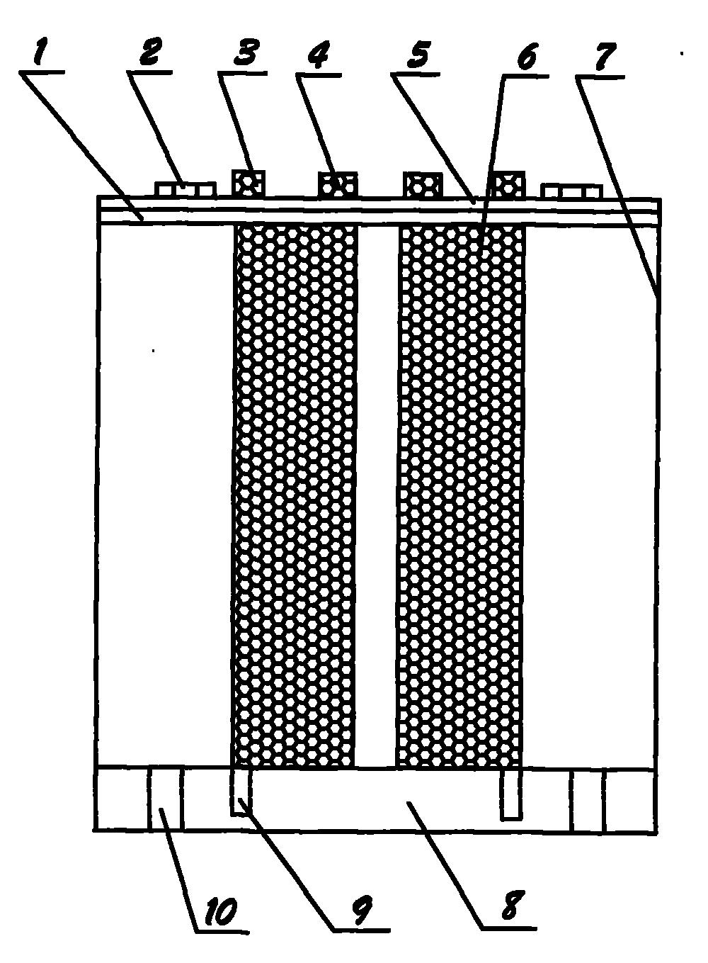
图1为本发明的结构示意图。Fig. 1 is a structural schematic diagram of the present invention.
图2为图1的俯视图。FIG. 2 is a top view of FIG. 1 .
具体实施方式 Detailed ways
下面结合附图说明本发明的具体实施方式。The specific implementation manner of the present invention will be described below in conjunction with the accompanying drawings.
如图1、图2所示,本发明的一种设在矿浆取样器入口的流量控制装置,其特征在于包括两端分别设有轴孔的底座8,与此底座8相连接的框架7,与此框架7的上部相连接的调整板1,与此调整板1相靠接的锁定板5,一端分别与所述的底座8相连接的一组控制板,此组控制板的另一端分别与所述的调整板1和锁定板5相连接,所述的调整板1上设有Y形槽,此Y形槽的上部为V形滑槽11,下部为调整板溢流槽12,在此调整板溢流槽12的两侧分别对称设有定位滑槽14,在此定位滑槽14的下方分别对称设有锁紧槽17,所述的锁定板5上设有与所述调整板溢流槽12相对应的锁定板溢流槽15,在此锁定板溢流槽15的两侧分别设有与所述定位滑槽14相对应的定位孔13,在此定位孔13的下方设有与所述锁紧槽17相对应的锁紧孔16,所述的调整板溢流槽12与所述的锁定板溢流槽15重合形成完整的溢流槽,所述的框架7通过螺栓10与矿浆取样器相连接。As shown in Fig. 1 and Fig. 2, a kind of flow control device located at the inlet of the pulp sampler of the present invention is characterized in that it includes a
所述控制板6的一侧的顶部设有上定位轴3,其底部设有下定位轴9,所述控制板6的另一侧的顶部设有调整轴4,所述的上定位轴3与所述的定位滑槽14和所述的定位孔13相连接,所述的下定位轴9与所述底座8的轴孔相连接,所述的调整轴4与所述的V形滑槽11做滑动连接。The top of one side of the
所述的一组控制板为二个对称的控制板。The set of control boards is two symmetrical control boards.
所述的一组控制板的外表面设有一层耐磨层。A wear-resistant layer is provided on the outer surface of the set of control boards.
本发明的设在矿浆取样器入口的流量控制装置的工作原理是:The operating principle of the flow control device located at the inlet of the pulp sampler of the present invention is:
首先将一组控制板的下定位轴9分别插入底座8的轴孔内,然后将锁定板5置于调整板1的上面,使锁定板5上的锁定板溢流槽15、定位孔13和锁紧孔16分别与调整板1上的调整板溢流槽12、定位滑槽14和锁紧槽17一一对应,将此组控制板的上定位轴3分别插入定位滑槽14和定位孔13内,将此组控制板的调整轴4分别插入V形滑槽11内,这时通过推拉调整轴4来调整取样口的大小。当沿V形滑槽11向上方推时,取样口扩大。当沿V形滑槽11向下拉时,取样口缩小。按照生产要求调整好取样口的大小后,将螺栓插入锁紧槽17和锁紧孔16,用螺母将其锁紧,完成一次取样口大小的调整。以此控制矿浆取样器入口的流量。First, the
由于控制板6的外表面设有一层耐磨层,提高了控制板6的耐磨性,延长了其使用寿命。同时控制板6磨损时,可更换控制板,达到延长矿浆取样器的使用寿命的目的。Since the outer surface of the
Claims (3)
Priority Applications (1)
| Application Number | Priority Date | Filing Date | Title |
|---|---|---|---|
| CN2009101874365A CN102023104B (en) | 2009-09-18 | 2009-09-18 | Flow control device arranged at entrance of ore pulp sampler |
Applications Claiming Priority (1)
| Application Number | Priority Date | Filing Date | Title |
|---|---|---|---|
| CN2009101874365A CN102023104B (en) | 2009-09-18 | 2009-09-18 | Flow control device arranged at entrance of ore pulp sampler |
Publications (2)
| Publication Number | Publication Date |
|---|---|
| CN102023104A CN102023104A (en) | 2011-04-20 |
| CN102023104B true CN102023104B (en) | 2012-06-06 |
Family
ID=43864667
Family Applications (1)
| Application Number | Title | Priority Date | Filing Date |
|---|---|---|---|
| CN2009101874365A Active CN102023104B (en) | 2009-09-18 | 2009-09-18 | Flow control device arranged at entrance of ore pulp sampler |
Country Status (1)
| Country | Link |
|---|---|
| CN (1) | CN102023104B (en) |
Families Citing this family (1)
| Publication number | Priority date | Publication date | Assignee | Title |
|---|---|---|---|---|
| CN113009094B (en) * | 2021-02-03 | 2023-07-07 | 禄根仪器(镇江)有限公司 | A New Type of High Efficiency Drug Dissolution Apparatus |
Citations (4)
| Publication number | Priority date | Publication date | Assignee | Title |
|---|---|---|---|---|
| SU1583784A1 (en) * | 1988-10-10 | 1990-08-07 | Криворожский горнорудный институт | Reducer of pulp samples |
| CN101347765A (en) * | 2008-09-01 | 2009-01-21 | 武汉理工大学 | Liquid level control device at side discharge end of trough flotation machine |
| CN201233537Y (en) * | 2008-07-23 | 2009-05-06 | 江西铜业集团公司 | Sand pump pipe entry amount regulation control device |
| CN201508497U (en) * | 2009-09-18 | 2010-06-16 | 鞍钢集团矿业公司 | Flow control device installed at the inlet of the slurry sampler |
-
2009
- 2009-09-18 CN CN2009101874365A patent/CN102023104B/en active Active
Patent Citations (4)
| Publication number | Priority date | Publication date | Assignee | Title |
|---|---|---|---|---|
| SU1583784A1 (en) * | 1988-10-10 | 1990-08-07 | Криворожский горнорудный институт | Reducer of pulp samples |
| CN201233537Y (en) * | 2008-07-23 | 2009-05-06 | 江西铜业集团公司 | Sand pump pipe entry amount regulation control device |
| CN101347765A (en) * | 2008-09-01 | 2009-01-21 | 武汉理工大学 | Liquid level control device at side discharge end of trough flotation machine |
| CN201508497U (en) * | 2009-09-18 | 2010-06-16 | 鞍钢集团矿业公司 | Flow control device installed at the inlet of the slurry sampler |
Also Published As
| Publication number | Publication date |
|---|---|
| CN102023104A (en) | 2011-04-20 |
Similar Documents
| Publication | Publication Date | Title |
|---|---|---|
| AU2018274955B2 (en) | Magnetic microfluidic concentrator, intelligent magnetic microfluidic concentrator, and complete set of beneficiation equipment using the same | |
| WO2008154184A3 (en) | Removable injection or production flow equalization valve | |
| CN103712870A (en) | Jet flow type mortar erosive wearing testing device with precise and controllable sand percentage | |
| CN201508497U (en) | Flow control device installed at the inlet of the slurry sampler | |
| CN201510933U (en) | Permanent magnet wet magnetic separator | |
| CN209465183U (en) | A kind of floating magnetic separation column device | |
| CN103175710A (en) | Continuous grit chamber sampler | |
| CN110538700A (en) | Discharging device capable of improving ore grinding medium filling rate of overflow type ball mill | |
| CN102023104A (en) | Flow control device arranged at entrance of ore pulp sampler | |
| CN208828773U (en) | A kind of threeway elephant trunk | |
| CN215673819U (en) | Valve gate | |
| CN218743219U (en) | Wear-resisting sieve plate for mining equipment | |
| CN204602332U (en) | A kind of discharge grid plate for screen analysis material | |
| CN107233997B (en) | Magnetic micro-fluidic concentrator with intelligent regulation and control function and complete set of magnetic separation equipment thereof | |
| CN201889230U (en) | Tail shaft device of spiral classifier | |
| CN209271661U (en) | A flotation machine coarse sand discharge device | |
| CN204638329U (en) | That smooth and easyly can give ore deposit reelects ore grinding device | |
| CN204602331U (en) | A kind of novel partition panel structure | |
| CN201295636Y (en) | Novel magnetic force washing type dewatering tank | |
| CN204220269U (en) | A kind of full-automatic cleaning table | |
| CN201287069Y (en) | Turbulent current plate of mineral concentration classer | |
| CN202962645U (en) | Internally-installed type ore slurry hydraulic controller | |
| CN206454795U (en) | A kind of ore pulp part flow arrangement | |
| CN205495815U (en) | An adjustable sorting baffle for a dry magnetic separator | |
| CN204564322U (en) | There is half countercurrent magnetic separator cell of magnetic liner plate protection |
Legal Events
| Date | Code | Title | Description |
|---|---|---|---|
| C06 | Publication | ||
| PB01 | Publication | ||
| C10 | Entry into substantive examination | ||
| SE01 | Entry into force of request for substantive examination | ||
| C14 | Grant of patent or utility model | ||
| GR01 | Patent grant | ||
| C56 | Change in the name or address of the patentee | ||
| CP01 | Change in the name or title of a patent holder |
Address after: 114001 Anshan District, Liaoning, No. 219 Road, No. 39, Tiedong Patentee after: Anshan Iron and Steel Group Mining Co., Ltd. Address before: 114001 Anshan District, Liaoning, No. 219 Road, No. 39, Tiedong Patentee before: Angang Group Mine Company |