CN102009576A - Single trailing arm suspension deceleration type wheel electric drive system - Google Patents
Single trailing arm suspension deceleration type wheel electric drive system Download PDFInfo
- Publication number
- CN102009576A CN102009576A CN 201010567793 CN201010567793A CN102009576A CN 102009576 A CN102009576 A CN 102009576A CN 201010567793 CN201010567793 CN 201010567793 CN 201010567793 A CN201010567793 A CN 201010567793A CN 102009576 A CN102009576 A CN 102009576A
- Authority
- CN
- China
- Prior art keywords
- wheel
- arm suspension
- motor
- drive system
- hub
- Prior art date
- Legal status (The legal status is an assumption and is not a legal conclusion. Google has not performed a legal analysis and makes no representation as to the accuracy of the status listed.)
- Granted
Links
Images

Abstract
The invention discloses a single trailing arm suspension deceleration type wheel electric drive system. An A-shaped single trailing arm suspension swing arm is supported at two ends of a motor shaft through a sliding bearing and a sliding bearing cover and is connected with one end of an axle; the other end of the axle is connected with a hub through a hub bearing; the hub, a rim and a brake drum are fixedly connected through a bolt; a pinion wheel is arranged on an output shaft of a motor through a flat key; and a gear wheel is arranged on the brake drum through a plurality of bolts and is engaged with the pinion wheel. The invention has the advantages that: the single trailing arm suspension deceleration type wheel electric drive system is compact and has high transmission efficiency; the driving force of each wheel is independent and controllable to facilitate the operation stability and comfort of vehicles.
Description
Technical field
The present invention relates to the drive system of electronlmobil, particularly a kind of single longitudenal arm suspension slowdown type wheel limit power drive system.
Background technology
Electronlmobil can be divided into concentrated type motor-driven and electric drive wheel drive form according to the different modes of power wheel mode.Concentrate the type motor-driven transmission of power generally to pass through retarder, diff, transmission shaft, mechanicals device such as universal-joint are passed to drive wheel.This drive form complex structure, driving efficiency is low, can't realize the independent control of wheel.
The electric drive wheel drive form then with the motor direct mount in drive wheel, drive system and complete vehicle structure are succinct, driving efficiency is high, the drive torque of each electric drive wheel also can independently be controlled, and helps improving the rideability under the abominable pavement conditions.Electric drive wheel drives used motor and mainly is divided into high speed inner rotor motor and low speed external rotor electric machine.High speed inner rotor motor volume is little, light weight, cost low power density height, but generally must be after the deceleration of the epicyclic reduction gear in being installed on wheel with transmission of power to wheel; External rotor electric machine can provide higher torque direct drive wheel, and mechanism is simple, but it self volume is big, and quality is big, and power density is low.Therefore no matter be the high speed internal rotor or the electric drive wheel of low speed outer rotor motor driven, their nonspring carried mass is all bigger, and motor size and quality are very limited.
The electric drive wheel transmission is compared with concentrated drive of motor and is had greater advantage, but deficiency also clearly.
Summary of the invention
Technical matters to be solved by this invention is that a kind of nonspring carried mass that reduces will be provided, and compact conformation is succinct, the single longitudenal arm suspension slowdown type wheel limit power drive system that driving efficiency is high.The present invention utilizes single longitudenal arm to be suspended in swing in the automobile side angle plane, with wheel rolling central axis and motor output shaft line parallel be arranged in this single longitudenal arm suspension two ends, so that in the suspension swing process, wheel rolling central axis and motor output shaft line parallel and distance are constant.Transmission of power between motor and the wheel can be a pair of gear, a pair of belt wheel or pair of sprocket transmission like this.By ratio of number of teeth is set, can also play slows down increases the effect of turning round in addition.The slowdown type wheel limit that the present invention can be used for non-wheel flutter drives, when two back-wheel drives, about respectively use a cover native system.
In order to solve above technical matters, the invention provides a kind of single longitudenal arm suspension slowdown type wheel limit power drive system, A font single longitudenal arm suspension swing arm is bearing on the motor shaft two ends by plain bearing and plain bearing lid, the single longitudenal arm suspension swing arm is connected with an end of axletree, the other end of axletree connects with wheel hub by hub bearing, and wheel hub, wheel rim and brake wheel are fixed together by bolt; Miniature gears is installed on the motor output shaft by flat key, and big gear wheel is installed in it on brake wheel by several bolts, and and pinion, make wheel rolling central axis and motor output shaft parallel axes and distance constant.
The motor housing place of plain bearing is provided with a convex shoulder respectively, and the two ends of plain bearing also are provided with convex shoulder, has limited the single longitudenal arm suspension swing arm and has moved along its axis, and has promptly limited the side force that the shifted laterally of wheel is transmitted.
Single longitudenal arm suspension swing arm of the present invention is connected with an end of axletree, plain bearing by the motor two ends is installed on the shell of motor, it also is the center of oscillation dead in line of the output shaft axis and the single longitudenal arm suspension of motor, wheel rim is supported on the axletree by hub bearing, and promptly the wheel rolling central axis overlaps with axle axis.Therefore, when wheel bounce, the motor output shaft axis remain parallel with the wheel rolling central axis and the distance constant.
The single longitudenal arm suspension swing arm passes through the sliding supported condition at motor two ends in the rear and front end of motor casing, because of motor shaft has the dimensions to tool, thereby make the swing arm part of single longitudenal arm suspension swing arm, also be that A type arm portion has certain span, when plain bearing and axle have under the certain interval situation, the axletree that bigger span causes-single longitudenal arm suspension swing arm is less in the rotation of vehicle level face, and the structure of A type arm improves the rigidity that suspension bears side force.More than two factors will reduce because of being suspended in the horizontal surface little commentaries on classics and side direction deformation the interference of driving system.This frame mode compact conformation simultaneously, avoided and motor shaft between constructive interference.
Brake system of the present invention can be used disc type brake or drum brake.
Superior effect of the present invention is: adopt slowdown type wheel limit power drive system, can use the high speed inner rotor motor that possesses high-specific-power.Motor and part deceleration transmission parts belong to spring carried mass, have reduced nonspring carried mass significantly compared to electric drive wheel, have also kept its plurality of advantages simultaneously.This system architecture is compact succinctly, driving efficiency is high, and propulsive effort of each wheel is independent controlled, helps improving handling stability, the traveling comfort of vehicle.
Description of drawings
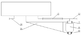
Fig. 1 is a structural representation of the present invention;
Fig. 2 is gear-driven principle schematic for the present invention adopts;
Fig. 3 adopts band/chain-drive principle schematic for the present invention;
The number in the figure explanation
1-brake wheel; 2-wheel rim;
3-hub bearing; 4-wheel hub;
5-miniature gears; 6-plain bearing lid C;
7-plain bearing A; 8-motor;
9-plain bearing lid D; 10-plain bearing B;
11-single longitudenal arm suspension swing arm; 12-big gear wheel;
13-small pulley/minor sprocket; 14-big belt wheel/hinge wheel;
15-driving band/messenger chain; 16-axletree.
The specific embodiment
See also shown in the accompanying drawing, the invention will be further described.
As shown in Figure 1, the present invention is illustrated adopting gear transmission mode and being equipped with drum brake mechanism, and the system of other type of drive and outfit plate disc brake only needs make an amendment slightly on this basis, is not specifically addressed here.
As shown in Figure 1, miniature gears 5 is installed on motor output shaft by flat key, and big gear wheel 12 is by obtaining power with miniature gears 5 engagements.Big gear wheel 12 is installed on it on brake wheel 1 by several bolts, and brake wheel 1, wheel hub 4 and wheel rim 2 are in the same place by bolt, but just drive wheels of big gear wheel 12 like this.The inner ring of wheel hub 4 is supported on the outer ring of hub bearing 3, and the inner ring of hub bearing 3 is supported on the axletree part of axletree 16 and single longitudenal arm suspension swing arm 11.Hub bearing 3 is by the convex shoulder on retaining nut, axletree 16 and the single longitudenal arm suspension swing arm 11, the convex shoulder and the circlip for bore location and installation of wheel hub 4.
Motor 8 is hinged by elastic caoutchouc and is connected to vehicle frame.The shell at motor 8 two ends is made cylindrical and its line of centers and motor 8 output shaft deads in line.The swing arm part and the bearing cap shim 6C of axletree 16 and single longitudenal arm suspension swing arm 11,9D passes through bolted connection, form an interior ring bearing in plain bearing 7A, the outer ring of 10B, plain bearing 7A, the 10B inner ring is supported on the cylindrical position, front and back of motor casing, because of motor shaft has the dimensions to tool, so the swing arm of axletree 16 and single longitudenal arm suspension swing arm 11 partly forms the A font, A font bottom has certain span, little commentaries on classics that this span is suspended in the horizontal surface when making and to have certain interval because of bearing with axle reduces, increased the rigidity that suspension bears side force simultaneously, reduced be suspended in rotate in the horizontal surface and deformation to miniature gears 5, the interference effect that big gear wheel 12 transmissions produce, compact conformation simultaneously, avoided and motor shaft between constructive interference.The motor housing place that is used to install plain bearing 7A, 10B is provided with a convex shoulder respectively, the two ends of plain bearing 7A, 10B also are provided with convex shoulder, thereby limited axletree 16 and single longitudenal arm suspension swing arm 11 moves along its axis, limit the shifted laterally of wheel in this way, born the side force that wheel passes over.
In addition in axletree 16 and the single longitudenal arm suspension swing arm 11, axle axis and swing arm centre of gration parallel axes have guaranteed that in the wheel bounce process wheel rolling central axis is parallel all the time with the motor output shaft axis and distance is constant.Like this, miniature gears 5 just can mesh all the time with big gear wheel 12.As shown in Figure 2, motor 8 is given miniature gears 5 with transmission of power, and big gear wheel 12 meshes with acquisition power with miniature gears 5, and then drive wheels.
In the present embodiment, motor 8, miniature gears 5 all belong to spring carried mass.
In the present embodiment, spring can be selected torsion bar spring or coil spring.
As shown in Figure 3, transmission adopted band of the present invention/chain-driving mode, the motor 8 that is fixed on the vehicle frame is given small pulley/minor sprocket 13 with transmission of power, and this small pulley/minor sprocket 13 drives big belt wheel/hinge wheel 14 by driving band/messenger chain 15 and rotates, and then drive wheels.
Claims (2)
1. a single longitudenal arm suspension slowdown type is taken turns the limit power drive system, it is characterized in that: A font single longitudenal arm suspension swing arm is bearing on the motor shaft two ends by plain bearing and plain bearing lid, the single longitudenal arm suspension swing arm is connected with an end of axletree, the other end of axletree connects with wheel hub by hub bearing, and wheel hub, wheel rim and brake wheel are fixed together by bolt; Miniature gears is installed on the motor output shaft by flat key, and big gear wheel is installed in it on brake wheel by several bolts, and and pinion, make wheel rolling central axis and motor output shaft parallel axes and distance constant.
2. single longitudenal arm suspension slowdown type wheel according to claim 1 limit power drive system, it is characterized in that: the motor housing place of plain bearing is provided with a convex shoulder respectively, the two ends of plain bearing also are provided with convex shoulder, limit the single longitudenal arm suspension swing arm and moved along its axis, promptly limited the side force that the shifted laterally of wheel is transmitted.
Priority Applications (1)
| Application Number | Priority Date | Filing Date | Title |
|---|---|---|---|
| CN 201010567793 CN102009576B (en) | 2010-12-01 | 2010-12-01 | Single trailing arm suspension deceleration type wheel electric drive system |
Applications Claiming Priority (1)
| Application Number | Priority Date | Filing Date | Title |
|---|---|---|---|
| CN 201010567793 CN102009576B (en) | 2010-12-01 | 2010-12-01 | Single trailing arm suspension deceleration type wheel electric drive system |
Publications (2)
| Publication Number | Publication Date |
|---|---|
| CN102009576A true CN102009576A (en) | 2011-04-13 |
| CN102009576B CN102009576B (en) | 2013-04-17 |
Family
ID=43839984
Family Applications (1)
| Application Number | Title | Priority Date | Filing Date |
|---|---|---|---|
| CN 201010567793 Active CN102009576B (en) | 2010-12-01 | 2010-12-01 | Single trailing arm suspension deceleration type wheel electric drive system |
Country Status (1)
| Country | Link |
|---|---|
| CN (1) | CN102009576B (en) |
Cited By (9)
| Publication number | Priority date | Publication date | Assignee | Title |
|---|---|---|---|---|
| CN102673365A (en) * | 2012-06-01 | 2012-09-19 | 同济大学 | Hybrid power electric automobile driving system by utilizing synchronous belt transmission |
| CN104890504A (en) * | 2015-06-03 | 2015-09-09 | 同济大学 | Integral speed reduction type electric wheel driving system for trapezoidal linkage type independent suspension |
| CN110001381A (en) * | 2019-04-16 | 2019-07-12 | 智导灵(苏州)智能科技有限公司 | A kind of new-energy automobile wheel side separated type drive assembly |
| CN111038248A (en) * | 2019-12-24 | 2020-04-21 | 武汉理工大学 | Electric wheel for vehicle and electric vehicle |
| CN111873783A (en) * | 2019-10-24 | 2020-11-03 | 中国北方车辆研究所 | Strengthen heat dissipation type in-wheel motor trailing arm suspension |
| CN111923721A (en) * | 2019-10-24 | 2020-11-13 | 中国北方车辆研究所 | Single trailing arm in-wheel motor drive module |
| CN113844214A (en) * | 2021-10-21 | 2021-12-28 | 合肥正浩机械科技有限公司 | Tire cooling structure |
| CN114312263A (en) * | 2020-09-30 | 2022-04-12 | 比亚迪股份有限公司 | Motor drive structure and car |
| RU213826U1 (en) * | 2021-07-12 | 2022-09-29 | Леонид Анатольевич Анистратенко | TANGENTIAL ELECTROMECHANICAL DRIVE OF ELECTRIC TRANSPORT |
Citations (8)
| Publication number | Priority date | Publication date | Assignee | Title |
|---|---|---|---|---|
| US4529223A (en) * | 1982-07-15 | 1985-07-16 | Mazda Motor Corporation | Vehicle rear-suspension mechanism |
| JPH0277327A (en) * | 1988-05-31 | 1990-03-16 | Jean-Claude Andruet | Electric motor car |
| WO2005000621A1 (en) * | 2003-06-25 | 2005-01-06 | Toyota Jidosha Kabushiki Kaisha | Suspension system for suspending a wheel having a motor therein |
| JP2005170150A (en) * | 2003-12-09 | 2005-06-30 | Nissan Motor Co Ltd | Wheel motor supporting structure |
| CN2719716Y (en) * | 2004-07-15 | 2005-08-24 | 北京嘉捷源技术开发有限公司 | Driving rear axle for superlow flooring airport ferry vehicle |
| CN1760067A (en) * | 2005-07-29 | 2006-04-19 | 上海燃料电池汽车动力系统有限公司 | Coupling structure between indendent suspension of single longitudinal swing arm, disc brake and electric drive wheel of external rotor |
| CN2832575Y (en) * | 2005-07-29 | 2006-11-01 | 上海燃料电池汽车动力系统有限公司 | Connecting structure of single longitudinal swing arm, independent suspension, disc type brake and internal rotor electric wheel |
| CN101342848A (en) * | 2008-08-15 | 2009-01-14 | 同济大学 | Double trailing arm type suspension fork wheel edge drive structure of new-type electric car |
-
2010
- 2010-12-01 CN CN 201010567793 patent/CN102009576B/en active Active
Patent Citations (8)
| Publication number | Priority date | Publication date | Assignee | Title |
|---|---|---|---|---|
| US4529223A (en) * | 1982-07-15 | 1985-07-16 | Mazda Motor Corporation | Vehicle rear-suspension mechanism |
| JPH0277327A (en) * | 1988-05-31 | 1990-03-16 | Jean-Claude Andruet | Electric motor car |
| WO2005000621A1 (en) * | 2003-06-25 | 2005-01-06 | Toyota Jidosha Kabushiki Kaisha | Suspension system for suspending a wheel having a motor therein |
| JP2005170150A (en) * | 2003-12-09 | 2005-06-30 | Nissan Motor Co Ltd | Wheel motor supporting structure |
| CN2719716Y (en) * | 2004-07-15 | 2005-08-24 | 北京嘉捷源技术开发有限公司 | Driving rear axle for superlow flooring airport ferry vehicle |
| CN1760067A (en) * | 2005-07-29 | 2006-04-19 | 上海燃料电池汽车动力系统有限公司 | Coupling structure between indendent suspension of single longitudinal swing arm, disc brake and electric drive wheel of external rotor |
| CN2832575Y (en) * | 2005-07-29 | 2006-11-01 | 上海燃料电池汽车动力系统有限公司 | Connecting structure of single longitudinal swing arm, independent suspension, disc type brake and internal rotor electric wheel |
| CN101342848A (en) * | 2008-08-15 | 2009-01-14 | 同济大学 | Double trailing arm type suspension fork wheel edge drive structure of new-type electric car |
Cited By (11)
| Publication number | Priority date | Publication date | Assignee | Title |
|---|---|---|---|---|
| CN102673365A (en) * | 2012-06-01 | 2012-09-19 | 同济大学 | Hybrid power electric automobile driving system by utilizing synchronous belt transmission |
| CN104890504A (en) * | 2015-06-03 | 2015-09-09 | 同济大学 | Integral speed reduction type electric wheel driving system for trapezoidal linkage type independent suspension |
| CN104890504B (en) * | 2015-06-03 | 2017-04-05 | 同济大学 | A kind of integrated trapezoidal link-type independent suspension speed-reducing type wheel power drive system |
| CN110001381A (en) * | 2019-04-16 | 2019-07-12 | 智导灵(苏州)智能科技有限公司 | A kind of new-energy automobile wheel side separated type drive assembly |
| CN111873783A (en) * | 2019-10-24 | 2020-11-03 | 中国北方车辆研究所 | Strengthen heat dissipation type in-wheel motor trailing arm suspension |
| CN111923721A (en) * | 2019-10-24 | 2020-11-13 | 中国北方车辆研究所 | Single trailing arm in-wheel motor drive module |
| CN111923721B (en) * | 2019-10-24 | 2022-04-29 | 中国北方车辆研究所 | Single trailing arm in-wheel motor drive module |
| CN111038248A (en) * | 2019-12-24 | 2020-04-21 | 武汉理工大学 | Electric wheel for vehicle and electric vehicle |
| CN114312263A (en) * | 2020-09-30 | 2022-04-12 | 比亚迪股份有限公司 | Motor drive structure and car |
| RU213826U1 (en) * | 2021-07-12 | 2022-09-29 | Леонид Анатольевич Анистратенко | TANGENTIAL ELECTROMECHANICAL DRIVE OF ELECTRIC TRANSPORT |
| CN113844214A (en) * | 2021-10-21 | 2021-12-28 | 合肥正浩机械科技有限公司 | Tire cooling structure |
Also Published As
| Publication number | Publication date |
|---|---|
| CN102009576B (en) | 2013-04-17 |
Similar Documents
| Publication | Publication Date | Title |
|---|---|---|
| CN102009576B (en) | Single trailing arm suspension deceleration type wheel electric drive system | |
| US6199651B1 (en) | Vehicle drive wheel assembly | |
| CN102555770B (en) | Speed-reducing wheel-rim driving system using mass of motor as mass of power vibration absorber | |
| CN201872602U (en) | Wheel reduction electric wheel having drum brake | |
| CN202294238U (en) | Synchronous belt speed-reducing type wheel rim electric driving system of integrated single-swinging-arm torsion beam suspension | |
| CN107458221A (en) | A kind of double reduction formula Direct wheel drives system | |
| CN102745073B (en) | Integrated single swinging arm suspension synchronous belt reduction type hub electric-drive system with tension device | |
| CN101985278B (en) | Reduction type wheel electric drive and vertical jitter type suspension system of electric vehicle | |
| CN108128141B (en) | Force transmission method of electric wheel and vehicle using same | |
| CN201129428Y (en) | Differential transmission apparatus of electric vehicle | |
| CN202174932U (en) | Integrated hub reduction type electric driving system with single-trailing-arm suspension | |
| CN204845388U (en) | Two motor drive bridge constructions | |
| CN102555772A (en) | Speed reduction type hub driving system with function of power shock absorption | |
| CN209814176U (en) | Motor tricycle with novel differential mechanism | |
| CN103707749B (en) | A kind of integration single longitudenal arm gear speed-reducing type wheel power drive system | |
| CN201440626U (en) | Back shaft motor mechanism of brushless differential electric motorcar | |
| CN203766513U (en) | Single trailing arm suspension synchronous belt deceleration type electric wheel drive system with tension device | |
| CN200953507Y (en) | External side disc type brake planetary frame outputting external rotor integrated motor-driven wheel structure | |
| CN203543558U (en) | Integrated single-longitudinal-arm suspension wheel side electric-driving system with tensioning mechanism | |
| CN113291151A (en) | Drive axle of integrated input shaft position variable reduction gearbox for snow sweeper | |
| CN201261391Y (en) | Rear axle differential mechanism assembly of four-wheel motorcycle | |
| CN2441774Y (en) | Walking mechanism for material stacking and taking device | |
| CN203832218U (en) | Synchronous belt speed-reduction wheel electric driving system with tensioning Macpherson suspension | |
| CN201784789U (en) | Electric vehicle speed reducing integral rear axle assembly | |
| CN101780832B (en) | Speed-reducing and rear axle integrated assembly of electric vehicle |
Legal Events
| Date | Code | Title | Description |
|---|---|---|---|
| C06 | Publication | ||
| PB01 | Publication | ||
| C10 | Entry into substantive examination | ||
| SE01 | Entry into force of request for substantive examination | ||
| C14 | Grant of patent or utility model | ||
| GR01 | Patent grant |