CN102009373A - Steel tube abrader - Google Patents
Steel tube abrader Download PDFInfo
- Publication number
- CN102009373A CN102009373A CN 201010562348 CN201010562348A CN102009373A CN 102009373 A CN102009373 A CN 102009373A CN 201010562348 CN201010562348 CN 201010562348 CN 201010562348 A CN201010562348 A CN 201010562348A CN 102009373 A CN102009373 A CN 102009373A
- Authority
- CN
- China
- Prior art keywords
- belt pulley
- contained
- conveying roller
- frame
- swing arm
- Prior art date
- Legal status (The legal status is an assumption and is not a legal conclusion. Google has not performed a legal analysis and makes no representation as to the accuracy of the status listed.)
- Pending
Links
Images

Abstract
The invention discloses a steel tube abrader comprising a rack and a grinding head arranged on the rack. The steel tube abrader is characterized by being provided with at least one pair of convey rollers driving a steel tube to move axially. The grinding head is provided with a rolling element equipped with a through hole which just faces to the axial convey pipeline of the steel tube; and at least one end surface of the rolling element is movably provided with at least one centrifugal swing arm by a hinge pin, and one surface of the centrifugal swing arm, which just faces to the through hole of the rolling element, is provided with an abrading material. Compared with the existing steel tube abrader, the steel tube abrader has the advantage of solving the problems of low production efficiency, poor adaptability to different pipe diameters and unstable processing quality of the existing steel tube abrader which is difficult to process and operate.
Description
Technical field
The present invention relates to the metalworking machinery technical field, especially a kind of machinery that is used for the metal circular steel tube surface is polished processing.
Background technology
Some metal circular tubes needs the surface is polished after producing before use, and especially used stainless pipe in the decoration industry just need polish its outer surface in process of production.Existing this stainless steel tube sanding machine just has polytype.One type steel pipe sanding machine wherein, its bistrique is the sanding machine that rotates around the steel pipe axis for the grinding position of steel pipe, this sanding machine is because the Grinding Contact line of bistrique can't be done oversizely, therefore can only process short tubing, production efficiency is low, to engage in production efficient and can polish long steel pipe in order to carry, such steel pipe sanding machine also has the sanding machine of a plurality of grinding wheel head structures, this sanding machine just adopts a plurality of bistriques simultaneously the multistage of a long tube to be carried out polishing operation simultaneously along the arrangement of steel pipe length direction, this machine cost is very high, uses uneconomical; Its bistrique of tubing sanding machine of another type is with respect to the steel pipe sanding machine, its bistrique is the sanding machine that moves along the steel pipe axis direction for the grinding position of steel pipe, the bistrique of this sanding machine will have the groove shape that the pipe cylindrical with required polishing matches, and the groove on this bistrique generally can only coat 1/4 outer girth of steel pipe, therefore, at least to carry out four athleticisms back and forth to steel pipe and grind a steel pipe, not only production efficiency is not high, but also there is following point: the one, the bistrique of requirement sanding machine will coincide with the machined steel tube-surface, different steel pipes are needed different bistriques, the bistrique bad adaptability; The 2nd, there is the overlapping or situation of leaking mill between polishing scratch in the trade union that adds several times back and forth; The 3rd, the time cutter amount of bistrique need be adjusted often according to wear extent, and operating technology requires high, the crudy instability.
Summary of the invention
Task of the present invention provides a kind of steel pipe sanding machine, it can solve existing steel pipe sanding machine production efficiency low, to the bad adaptability and the crudy problem of unstable of different tube diameters.
In order to realize above-mentioned task, this steel pipe sanding machine includes frame and the bistrique that is contained on the frame, has a secondary conveying roller that drives the steel pipe axially-movable at least, described bistrique has a rotor, this rotor has one over against the through hole of steel shaft to transfer passage, by bearing pin at least one centrifugal swing arm is housed versatilely at least one end face of described rotor, described centrifugal swing arm is equipped with removing material over against the one side of the through hole of described rotor.
As one of preferred version of above-mentioned steel pipe sanding machine can be: described rotor be to be contained in belt pulley on the described frame by bearing and bearing block, each end face of this belt pulley all is equipped with two described centrifugal swing arms, and this belt pulley is connected with the belt pulley of engine on being contained in frame by driving belt; Described conveying roller has two pairs, they are connected with engine on being contained in described frame by mechanical driving device, the roll shaft axis horizontal of this two secondary conveying roller is provided with, this two secondary conveying roller is contained in the both sides of described belt pulley central through hole respectively, at least therein between a secondary described conveying roller and the described bistrique, a secondary roll shaft axis is housed erects the guide roller that is provided with.
As two of the preferred version of above-mentioned steel pipe sanding machine can be: described rotor be to be contained in belt pulley on the described frame by bearing and bearing block, each end face of this belt pulley all is equipped with two described centrifugal swing arms, described removing material has two parts, this two parts removing material passes the central through hole of described belt pulley, the two ends of the described removing material of each part are installed in respectively in the centrifugal swing arm of these belt pulley both ends of the surface, and described belt pulley is connected with the belt pulley of engine on being contained in frame by driving belt; Described conveying roller has two pairs, they are connected with engine on being contained in described frame by mechanical driving device, the roll shaft axis horizontal of this two secondary conveying roller is provided with, this two secondary conveying roller is contained in the both sides of described belt pulley central through hole respectively, at least therein between a secondary described conveying roller and the described bistrique, the guide roller that a secondary roll shaft axis vertically is provided with is housed; In this preferred version, the roll shaft axis of above-mentioned conveying roller also can be to erect to be provided with, and in this case, the roll shaft axis of corresponding described guide roller then adopts and is horizontally disposed with.
In the various technical schemes of above-mentioned steel pipe sanding machine, the removing material that is connected in the described centrifugal swing arm generally is an end that is contained in this centrifugal swing arm, the other end of this centrifugal swing arm is provided with the counterweight stone roller, and described bearing pin is installed in the upper pin shaft hole between described removing material and counterweight stone roller of described centrifugal swing arm; Driving conveying roller can be an identical power machine with the engine that drives rotor, also can be a plurality of power machines that separate, and described engine can be a motor, also can be internal combustion engine.
Adopted the steel pipe sanding machine of such scheme to compare and had following beneficial effect with existing steel pipe sanding machine:
1, the steel pipe that is ground can disposable grinding be finished whole steel pipe, does not need back and forth movement, so the production efficiency height.
2, because the abrasive material of contact steel pipe is to be contained in the centrifugal swing arm, when work is to be crimped on the outer surface of steel tube, its pressure to steel pipe is determined according to the rotating speed of rotor, all equally can grinding to the steel pipe of different tube diameters, the wearing and tearing of abrasive material are not needed to carry out yet the adjusting of the depth of cut as prior art, therefore, strong to the adaptability of processing caliber, low to the specification requirement of process operation.
3, can obtain the mill line of stable stock removal and uniformity by the slewing rate of control transfer rate of conveying roller and rotor, therefore, to the polishing quality height of steel pipe.
Description of drawings
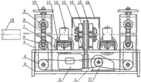
Fig. 1 is the front view of the embodiment of the invention;
Fig. 2 is the left view of the embodiment of the invention;
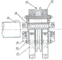
Fig. 3 is the grinding wheel head structure front view of the embodiment of the invention;
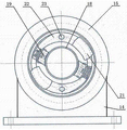
Fig. 4 is the grinding wheel head structure left view of the embodiment of the invention.
The specific embodiment
The invention will be further described below in conjunction with accompanying drawing embodiment:
Fig. 1, this steel pipe sanding machine shown in Figure 2 has a frame 3, two variable-speed motors 2 are housed under the table top of frame 3,17, on the table top of frame 3, the conveying roller that a secondary roll shaft axis horizontal is provided with respectively is equipped with at the two ends that are positioned at frame 3, every secondary conveying roller has the roll shaft of passing through, bearing is contained in a lower roller 6 and the upper roller 9 on the conveying roller support 5, the screw mandrel that connects handwheel 10 is housed on conveying roller support 5, screw mandrel is provided with two sections screw threads that rotation direction is opposite, these two sections screw threads are screwed in respectively on the bearing block of the bearing block of upper roller 9 and lower roller 6, the rotation that drives screw mandrels by handwheel 10 can be regulated the distance between upper roller 9 and 6 faces of lower roller, carry the steel pipe 18 of different tube diameters to adapt to crimping, the axle of lower roller 6 wherein is connected with the belt pulley of chain gearing 1 with variable-speed motor 17 by belt drive unit 4, wherein the driven pulley of belt drive unit 4 directly is connected on the axle of lower roller 6, and the bearing block of drive pulley is fixedlyed connected with the bearing block of lower roller 6 and is contained in the slideway of conveying roller support 5.On the table top of frame 3, be positioned at the central authorities of two secondary conveying rollers, by bearing block 14 pair being housed is the bistrique that main body constitutes with belt pulley 15, be provided with protective cover 16 in the bistrique outside, the belt pulley 15 of bistrique is connected with the belt pulley of a variable-speed motor 2 in being contained in frame 3 by driving belt 13, one secondary roll shaft axis all is housed between bistrique and each secondary conveying roller erects the guide roller that is provided with, each secondary guide roller is erect two rollers 12 that are provided with by axis and is constituted side by side, the inert roller that these two rollers 12 are not drives, each roller 12 all is contained on the support 7 of rack table by bearing and bearing block, the bearing block of these two rollers 12 is respectively by being threaded on the adjusting screw mandrel 8 on the opposite thread segment of two sections rotation directions, an end of regulating screw mandrel 8 is equipped with adjusting handle 11, can regulate in the same secondary guide roller distance between two rollers 12 by rotating adjusting handle 11, make it to adapt to the guiding needs of the steel pipe 18 of the different sizes of grinding.
Fig. 3, bistrique shown in Figure 4, its rotor is a belt pulley 15, belt pulley 15 supports by bearing blocks 14 that the bearing 20 that is contained on its both sides shaft shoulder is installed in outside these two bearings 20, and these two bearing blocks 14 are contained on the table top of frame 3 by bolt as depicted in figs. 1 and 2.The center of belt pulley 15 has one to be used for by being ground the through hole of steel pipe, the axis of this through hole is as shown in Figure 1 over against the axis of determined steel pipe 18 transfer passages of two secondary conveying rollers, two end faces of belt pulley 15 all are equipped with two centrifugal swing arms 22 that structure is identical by bearing pin 23 with above-mentioned through hole symmetrically, the centrifugal swing arm 22 of its middle belt pulley 15 both ends of the surface is symmetrical arranged, one end of two centrifugal swing arms 22 of same bearing pin 23 installations two ends of folding as the emery cloth 19 of removing material of passing belt pulley 15 central through holes by abrasive material support and the bolt clamping that is contained in the abrasive material support respectively, the other end of every centrifugal swing arm 22 is equipped with counterweight stone roller 21 by bolt, the bearing pin 23 that centrifugal swing arm 22 is installed is installed in the centrifugal swing arm through hole between abrasive material support and the counterweight stone roller 21, design speed according to bistrique, the weight of counterweight stone roller in the centrifugal swing arm 22, and the position that through holes are installed in centrifugal swing arm 22 is provided with, and can make this machine obtain needed emery cloth 19 crimping when work and be ground pressure on the steel pipe 18.
Claims (5)
1. steel pipe sanding machine, include frame (3) and be contained in bistrique on the frame (3), it is characterized in that: have a secondary conveying roller that drives the steel pipe axially-movable at least, described bistrique has a rotor, this rotor has one over against the through hole of steel shaft to transfer passage, by bearing pin (23) at least one centrifugal swing arm (22) is housed versatilely at least one end face of described rotor, described centrifugal swing arm (22) is equipped with removing material (19) over against the one side of the through hole of described rotor.
2. steel pipe sanding machine according to claim 1, it is characterized in that: described rotor is to be contained in belt pulley (15) on the described frame (3) by bearing (20) and bearing block (14), each end face of this belt pulley (15) all is equipped with two described centrifugal swing arms (22), and this belt pulley (15) is connected with the belt pulley of engine (2) on being contained in frame (3) by driving belt (13); Described conveying roller has two pairs, they are connected with engine (17) on being contained in described frame (3) by mechanical driving device, the roll shaft axis horizontal of this two secondary conveying roller is provided with, this two secondary conveying roller is contained in the both sides of described belt pulley (15) central through hole respectively, at least therein between a secondary described conveying roller and the described bistrique, a secondary roll shaft axis is housed erects the guide roller that is provided with.
3. steel pipe sanding machine according to claim 1, it is characterized in that: described rotor is to be contained in belt pulley (15) on the described frame by bearing and bearing block, each end face of this belt pulley (15) all is equipped with two described centrifugal swing arms (22), described removing material (19) has two parts, this two parts removing material (19) passes the central through hole of described belt pulley (15), the two ends of the described removing material of each part (19) are installed in respectively in the centrifugal swing arm (22) of this belt pulley (15) both ends of the surface, and described belt pulley (15) is connected with the belt pulley of engine (2) on being contained in frame (3) by driving belt (13); Described conveying roller has two pairs, they are connected with engine (17) on being contained in described frame (3) by mechanical driving device, the roll shaft axis of this two secondary conveying roller is erect and is provided with, this two secondary conveying roller is contained in the both sides of described belt pulley (15) central through hole respectively, at least therein between a secondary described conveying roller and the described bistrique, the guide roller that a secondary roll shaft axis horizontal is provided with is housed.
4. steel pipe sanding machine according to claim 1, it is characterized in that: described rotor is to be contained in belt pulley (15) on the described frame by bearing and bearing block, each end face of this belt pulley (15) all is equipped with two described centrifugal swing arms (22), described removing material (19) has two parts, this two parts removing material (19) passes the central through hole of described belt pulley (15), the two ends of the described removing material of each part (19) are installed in respectively in the centrifugal swing arm (22) of this belt pulley (15) both ends of the surface, and described belt pulley (15) is connected with the belt pulley of engine (2) on being contained in frame (3) by driving belt (13); Described conveying roller has two pairs, they are connected with engine (17) on being contained in described frame (3) by mechanical driving device, the roll shaft axis horizontal of this two secondary conveying roller is provided with, this two secondary conveying roller is contained in the both sides of described belt pulley central through hole respectively, at least therein between a secondary described conveying roller and the described bistrique, a secondary roll shaft axis is housed erects the guide roller that is provided with.
5. according to claim 1,2,3 or 4 described steel pipe sanding machines, it is characterized in that: be connected the end that removing material (19) in the described centrifugal swing arm (22) is contained in this centrifugal swing arm (22), the other end of this centrifugal swing arm (22) is provided with counterweight stone roller (21), and described bearing pin (23) is installed on the pin shaft hole that is positioned in the described centrifugal swing arm (22) between described removing material (19) and the counterweight stone roller (21).
Priority Applications (1)
| Application Number | Priority Date | Filing Date | Title |
|---|---|---|---|
| CN 201010562348 CN102009373A (en) | 2010-11-29 | 2010-11-29 | Steel tube abrader |
Applications Claiming Priority (1)
| Application Number | Priority Date | Filing Date | Title |
|---|---|---|---|
| CN 201010562348 CN102009373A (en) | 2010-11-29 | 2010-11-29 | Steel tube abrader |
Publications (1)
| Publication Number | Publication Date |
|---|---|
| CN102009373A true CN102009373A (en) | 2011-04-13 |
Family
ID=43839800
Family Applications (1)
| Application Number | Title | Priority Date | Filing Date |
|---|---|---|---|
| CN 201010562348 Pending CN102009373A (en) | 2010-11-29 | 2010-11-29 | Steel tube abrader |
Country Status (1)
| Country | Link |
|---|---|
| CN (1) | CN102009373A (en) |
Cited By (7)
| Publication number | Priority date | Publication date | Assignee | Title |
|---|---|---|---|---|
| CN104608013A (en) * | 2015-01-26 | 2015-05-13 | 江苏海事职业技术学院 | Cylinder surface polishing device |
| CN107553233A (en) * | 2017-10-27 | 2018-01-09 | 孙冲 | A kind of spring raw material grinding apparatus |
| CN107649880A (en) * | 2016-07-26 | 2018-02-02 | 万象设计江苏有限责任公司 | A kind of pipe outer surface polishing tool of fixed length cutting |
| CN107869512A (en) * | 2016-09-27 | 2018-04-03 | Ntn株式会社 | Hydrodynamic bearing device shaft component and its manufacture method and Hydrodynamic bearing device |
| CN110052952A (en) * | 2019-06-05 | 2019-07-26 | 广州立奔杯业有限公司 | A kind of device of polishing and CuO surface |
| CN112571249A (en) * | 2021-01-04 | 2021-03-30 | 南京皓政科技有限公司 | Steel pipe rust cleaning device that polishes |
| CN115890370A (en) * | 2022-11-25 | 2023-04-04 | 普拉思工业技术(江苏)有限公司 | Polyurethane is manufacturing installation for submarine cable protector |
Citations (5)
| Publication number | Priority date | Publication date | Assignee | Title |
|---|---|---|---|---|
| CN2079101U (en) * | 1990-11-28 | 1991-06-19 | 吕森林 | Pipe grinding machine |
| CN2140807Y (en) * | 1992-11-23 | 1993-08-25 | 郑州锅炉厂 | Sealed rust-removing machine for external wall of steel tube |
| CN201030508Y (en) * | 2007-04-11 | 2008-03-05 | 华北石油管理局第一机械厂 | Steel pipe derusting apparatus |
| CN201164967Y (en) * | 2008-01-16 | 2008-12-17 | 蔡尚喜 | Propulsion unit of steel pipe rust cleaning machine |
| CN201863060U (en) * | 2010-11-29 | 2011-06-15 | 梁庆琨 | Steel tube burnish machine |
-
2010
- 2010-11-29 CN CN 201010562348 patent/CN102009373A/en active Pending
Patent Citations (5)
| Publication number | Priority date | Publication date | Assignee | Title |
|---|---|---|---|---|
| CN2079101U (en) * | 1990-11-28 | 1991-06-19 | 吕森林 | Pipe grinding machine |
| CN2140807Y (en) * | 1992-11-23 | 1993-08-25 | 郑州锅炉厂 | Sealed rust-removing machine for external wall of steel tube |
| CN201030508Y (en) * | 2007-04-11 | 2008-03-05 | 华北石油管理局第一机械厂 | Steel pipe derusting apparatus |
| CN201164967Y (en) * | 2008-01-16 | 2008-12-17 | 蔡尚喜 | Propulsion unit of steel pipe rust cleaning machine |
| CN201863060U (en) * | 2010-11-29 | 2011-06-15 | 梁庆琨 | Steel tube burnish machine |
Cited By (10)
| Publication number | Priority date | Publication date | Assignee | Title |
|---|---|---|---|---|
| CN104608013A (en) * | 2015-01-26 | 2015-05-13 | 江苏海事职业技术学院 | Cylinder surface polishing device |
| CN107649880A (en) * | 2016-07-26 | 2018-02-02 | 万象设计江苏有限责任公司 | A kind of pipe outer surface polishing tool of fixed length cutting |
| CN107869512A (en) * | 2016-09-27 | 2018-04-03 | Ntn株式会社 | Hydrodynamic bearing device shaft component and its manufacture method and Hydrodynamic bearing device |
| CN107869512B (en) * | 2016-09-27 | 2022-02-01 | Ntn株式会社 | Shaft member for fluid bearing device, method for manufacturing same, and fluid bearing device |
| CN107553233A (en) * | 2017-10-27 | 2018-01-09 | 孙冲 | A kind of spring raw material grinding apparatus |
| CN110052952A (en) * | 2019-06-05 | 2019-07-26 | 广州立奔杯业有限公司 | A kind of device of polishing and CuO surface |
| CN110052952B (en) * | 2019-06-05 | 2020-06-23 | 宝应县增厚铜业有限公司 | Device for polishing and oxidizing copper surface |
| CN112571249A (en) * | 2021-01-04 | 2021-03-30 | 南京皓政科技有限公司 | Steel pipe rust cleaning device that polishes |
| CN115890370A (en) * | 2022-11-25 | 2023-04-04 | 普拉思工业技术(江苏)有限公司 | Polyurethane is manufacturing installation for submarine cable protector |
| CN115890370B (en) * | 2022-11-25 | 2023-10-13 | 普拉思工业技术(江苏)有限公司 | Manufacturing device for polyurethane submarine cable protector |
Similar Documents
| Publication | Publication Date | Title |
|---|---|---|
| CN201863060U (en) | Steel tube burnish machine | |
| CN102009373A (en) | Steel tube abrader | |
| CN100553880C (en) | Thick/the fine machining integrated processing device of abrasive band centerless grinding and polishing | |
| CN2792703Y (en) | Conical roller spherical grinding machine with end face | |
| CN203221397U (en) | Novel steel tube polisher | |
| CN105058192B (en) | Chamfer machining mechanism inside and outside a kind of materials in the tube two | |
| CN203495704U (en) | Deburring device for steel plate | |
| CN106514455A (en) | Numerical control grinding machine for processing super large bearing spherical rollers | |
| CN106695530A (en) | Bearing roller spherical surface superfinishing mechanism | |
| CN206200688U (en) | A kind of New Abrasive Belt sharpening machine for steel tube surface | |
| CN102303279A (en) | Outer-diameter superfinishing machine tool for spherical roller | |
| CN115922483A (en) | Quick grinding device of inner wall for pipeline processing | |
| CN201023204Y (en) | Small diameter tube and thread polishing and burnishing machine | |
| CN201136118Y (en) | Abrasive band polisher for steel tubes | |
| CN204935343U (en) | Roller sphere mill overcharge is put | |
| CN203973341U (en) | A kind of Large Sand band polishing machine of processing deflector roll | |
| CN206405437U (en) | A kind of seamless pipe inside and outside wall processing unit (plant) | |
| CN202271260U (en) | Numerical control grinding machine for machining center hole and seat surface | |
| CN104959906A (en) | Cylindrical super-fine machine processing bearing ring | |
| CN103100940A (en) | Grinding mechanism for spherical end surface of bearing roller | |
| CN109531376B (en) | Compound machining device and method for grinding centerless excircle abrasive belt and inner hole magnetic force of pipe fitting | |
| CN101683717B (en) | Grinding machine equipment for grinding internal surface of column | |
| CN216327510U (en) | Stainless steel pipe surface finish device | |
| CN206677710U (en) | A kind of numerically control grinder for processing oversize bearing spherical surface roller | |
| CN108908035A (en) | A kind of magnesium-alloy tube bar outer surface arrangement for grinding |
Legal Events
| Date | Code | Title | Description |
|---|---|---|---|
| C06 | Publication | ||
| PB01 | Publication | ||
| C10 | Entry into substantive examination | ||
| SE01 | Entry into force of request for substantive examination | ||
| C02 | Deemed withdrawal of patent application after publication (patent law 2001) | ||
| WD01 | Invention patent application deemed withdrawn after publication |
Application publication date: 20110413 |