CN102004897B - Apparatus and method for processing image - Google Patents
Apparatus and method for processing image Download PDFInfo
- Publication number
- CN102004897B CN102004897B CN2010102420292A CN201010242029A CN102004897B CN 102004897 B CN102004897 B CN 102004897B CN 2010102420292 A CN2010102420292 A CN 2010102420292A CN 201010242029 A CN201010242029 A CN 201010242029A CN 102004897 B CN102004897 B CN 102004897B
- Authority
- CN
- China
- Prior art keywords
- face
- parameter
- image
- user
- model
- Prior art date
- Legal status (The legal status is an assumption and is not a legal conclusion. Google has not performed a legal analysis and makes no representation as to the accuracy of the status listed.)
- Expired - Fee Related
Links
Images


Classifications
-
- G—PHYSICS
- G06—COMPUTING; CALCULATING OR COUNTING
- G06T—IMAGE DATA PROCESSING OR GENERATION, IN GENERAL
- G06T11/00—2D [Two Dimensional] image generation
-
- G—PHYSICS
- G06—COMPUTING; CALCULATING OR COUNTING
- G06V—IMAGE OR VIDEO RECOGNITION OR UNDERSTANDING
- G06V40/00—Recognition of biometric, human-related or animal-related patterns in image or video data
- G06V40/10—Human or animal bodies, e.g. vehicle occupants or pedestrians; Body parts, e.g. hands
- G06V40/16—Human faces, e.g. facial parts, sketches or expressions
- G06V40/168—Feature extraction; Face representation
-
- G—PHYSICS
- G06—COMPUTING; CALCULATING OR COUNTING
- G06T—IMAGE DATA PROCESSING OR GENERATION, IN GENERAL
- G06T11/00—2D [Two Dimensional] image generation
- G06T11/60—Editing figures and text; Combining figures or text
-
- G—PHYSICS
- G06—COMPUTING; CALCULATING OR COUNTING
- G06V—IMAGE OR VIDEO RECOGNITION OR UNDERSTANDING
- G06V40/00—Recognition of biometric, human-related or animal-related patterns in image or video data
- G06V40/10—Human or animal bodies, e.g. vehicle occupants or pedestrians; Body parts, e.g. hands
- G06V40/16—Human faces, e.g. facial parts, sketches or expressions
- G06V40/174—Facial expression recognition
- G06V40/175—Static expression
Abstract
The invention relates to an apparatus, a method, and a program for processing image. The image processing apparatus includes a face detector for detecting a face region from an image including a face of a user, a part detector for detecting a positional layout of a part of the face included in the face region detected by the face detector, a determiner for determining an attribute of the face on the basis of the positional layout of the part detected by the part detector and calculating a score indicating attribute determination results, a model selector for selecting, on the basis of the score calculated by the determiner, a model that is to be displayed in place of the face of the user in the image, and an image generator for generating an image of a face of the model selected by the model selector and synthesizing the image of the face of the model with the face of the user within the face region.
Description
Technical field
The present invention relates to image processing apparatus, image processing method and image processing program, particularly, relate to be used to presenting user more image processing apparatus, image processing method and the image processing program of the image of susceptible to (amenable).
Background technology
A kind of typical image processing apparatus of prior art image processing apparatus face of user in detected image on real-time basis, and by the image section ground of face or entirely replace with another image of synchronizeing with the user's who detects face.
For example, the Patent Application Publication No.2005-157679 of Japanese unexamined discloses the technology of distinguishing the face image of any size of Performance Detection with height.The Patent Application Publication No.2005-284348 of Japanese unexamined discloses the technology of fast detecting face image.The Patent Application Publication No.2002-232783 of Japanese unexamined discloses the technology according to orientation bonding (gluing) face image of the pre-user who takes on multiple directions of the face image from detecting image.
The pre-face image of taking and can be replaced by the incarnation generated through computer graphics from the face image detected image by this way.The change of the countenance by detecting the user on real-time basis, the expression of replacing incarnation can be synchronizeed with the change of user's countenance.For example, the eyes of incarnation open or the opening of face of incarnation can change according to user's countenance.The smile degree of incarnation can change according to user's smile degree.
The Patent Application Publication No.2007-156650 of Japanese unexamined discloses the technology that produces the countenance of nature.The Patent Application Publication No.7-44727 of Japanese unexamined discloses the technology that changes mouth shape with voice synchronous ground.
Summary of the invention
By the face by user in image, replace with incarnation, the user can be subject to the impact of (in game or Virtual Space) image.User's this image of hopefully shifting one's love.
Thus, be desirable to provide the more susceptible image of user.
In one embodiment of the invention, a kind of image processing apparatus comprises: the face detection apparatus, for the image detection face area of the face from comprising the user; The part detector means, for detection of the location layout of the part that is included in this face in this face area detected by this face detection apparatus; The determiner device, determine that for the location layout of this part according to being detected by this part detector means the attribute of this face calculating show that attribute determines the mark of result; The Model Selection apparatus, select to replace this user's of image face and the model that shows for the mark according to being calculated by this determiner device; With the image generator device, for generation of the image of the face of the image of the face of this model of being selected by this Model Selection apparatus this user's in synthetic this face area face and this model.
In another embodiment of the present invention, in image processing method and image processing program comprises the steps: from the image detection face area of the face that comprises the user; Detection is included in the location layout of the part of this face in this face area; According to the location layout of this part, determine the attribute of this face and calculate and show that attribute determines the mark of result; According to this mark, selection will be replaced the face of this user in this image and the model that shows; Image with the face of the face of this user in the image of the face that produces selected model synthetic this face area and this model.
In yet another embodiment of the present invention, from comprising the image detection face area of user face, detection is included in the location layout of the part of the face in face area, according to the location layout of part, determines the attribute of face and calculate to show that attribute determines the mark of result.According to mark, select to replace user face in image and the model that shows.Produce selecteed model face image and with the image of the face of face's synthetic model of facial regions intra domain user.
In another embodiment of the present invention, provide thus the user susceptible image.
The accompanying drawing explanation
Fig. 1 is the block diagram of image processing apparatus according to an embodiment of the invention;
Fig. 2 A and 2B show the image processing process of image processing apparatus;
Fig. 3 shows the face detection object information;
Fig. 4 shows face location information;
Fig. 5 A and 5B show partial results information;
Fig. 6 shows the angle rotation that is included in the face area in the face detection object information and the attitude (posture) that is included in the face area in face location information;
Fig. 7 A and 7B show the filtration treatment of filtering treater;
Fig. 8 A-8C shows the parameter of the face orientation that shows incarnation;
Fig. 9 A-9C shows the parameter of the face location that shows incarnation;
Figure 10 A and 10B show the right eye that shows incarnation and the parameter of closing ratio of left eye;
Figure 11 A-11C shows the parameter that the face that shows incarnation opens ratio;
Figure 12 A and 12B show the parameter of the smile ratio that shows incarnation;
It is synthetic that Figure 13 shows expression;
Figure 14 is the process flow diagram by the image processing process of image processing apparatus execution;
Figure 15 is the process flow diagram that Model Selection is processed;
Figure 16 is the process flow diagram of face orientation correcting process;
Figure 17 shows and is used in the parameter of expressing one's feelings in synthesizing;
Figure 18 A and 18B show the synthetic processing of mouth shape;
Figure 19 is the block diagram of mouth shape compositor;
Figure 20 shows the example of parameter;
Figure 21 shows the key concept of the filtration treatment of parameter generator;
Figure 22 A-22C shows the variances sigma that error distributes
f 2Change and the output valve u of filtrator
pChange between relation;
Figure 23 A and 23B show the distribution of the speed component of the distribution of component of acceleration of state estimation end value and state estimation end value;
Figure 24 is the block diagram of filtering treater;
Figure 25 is the process flow diagram of the filtration treatment of filtering treater; With
Figure 26 shows the block diagram of computing machine according to an embodiment of the invention.
Embodiment
Describe with reference to the accompanying drawings embodiments of the invention in detail.
Fig. 1 is the block diagram of the image processing apparatus of one embodiment of the present of invention.
With reference to Fig. 1, image processing apparatus 11 is connected to camera 12 and display 13.
With reference to Fig. 2 A and 2B, the image processing process of Description Image treating apparatus 11 usually.Fig. 2 A shows by camera 12 and takes the image that then is input to image processing apparatus 11.Fig. 2 B shows by image processing apparatus 11 and process the image then shown on display 13.
As shown in fig. 1, image processing apparatus 11 comprises Camiera input unit 14, face recognition device 15, Model Selection device 16, parameter generator 17 and image generator 18.
The image that is input to Camiera input unit 14 from camera 12 is raw data (not being the data after image is processed when exporting from imaging device).Demoder 22 is the image of RGB+Y data (data of the three primary colours of expression red, green and blue and the image of brightness signal Y) by the image transitions of raw data, then image is fed to face recognition device 15.
Each element in 31 pairs of face recognition devices 15 of face recognition controller is carried out to control and is processed.For example, face recognition controller 31 is carried out to control and is processed, so that the output of attribute determiner 34 starts for example,, until the frame (15 frames) of predetermined quantity is supplied to Model Selection device 16, then after the frame of predetermined quantity, to be supplied to parameter generator 17 from the frame that new face detected.
If user's face is present in the image from Camiera input unit 14, the face detection object information of the face area of (identify) face is differentiated in 32 outputs of face detection processor so.If the new face of front in not being presented on image in general retrieval, detected, face detection processor 32 starts to export the face detection object information of new face so.When face was presented in image continuously, face detection processor 32 was followed the trail of face in the retrieval of part, and exports continuously the face detection object information of face.The face detection object information comprises reference point, horizontal width, vertical length and the anglec of rotation (X of face, the Y of face, the W of face, the H of face, face rotate (roll) and face's deflection (yaw)) of face area.
Below with reference to Fig. 3, the face detection object information is described.As shown in Figure 3, the reference point of face area (X of face, the Y of face) is carried out normalization as the upper left corner of whole image and (1,1) as the lower right corner of whole image with (0,0), and then the XY coordinate with the upper left corner of face area means.Reference point as face area, the horizontal width of face area and vertical length (W of face, the H of face) mean by line parallel, vertical with horizontal line, the normalized value in one side that serve as perpendicular line that serve as horizontal one side and face area with being connected two with face area.The anglec of rotation of face area (face's rotation, face's deflection) is indicated in the right-hand coordinate system that in Fig. 6, back will be discussed.
Part detecting device 33 (Fig. 1) detects right eye, left eye, nose and the face of the face part as user face in the face area detected by face detection processor 32, and output is as the partial information of the information of the coordinate of the central point that shows every part.In partial information, mean that each the coordinate of central point in right eye, left eye, nose and face is by with (0,0) expression is as the reference point (X of face, the Y of face) in the upper left corner of face area and the lower right corner normalization of (1,1) expression face area.
Part detecting device 33 is determined position and the attitude of face based on the geometric relationship of detected part, and output shows the position of face and the face location information of attitude.Face location information comprise the coordinate at four angles of face area and the attitude of face (regional X[0]-[3], regional Y[0]-[3], posture rotation, posture pitching (pitch), posture deflection).
Below with reference to Fig. 4, face location information is described.As shown in Figure 4, face area (regional X[0]-[3] and regional Y[0]-[3]) the coordinate at four angles by the upper left corner and (1,1) that means whole image with (0,0), mean that the normalized value in the lower right corner of whole image means.The attitude of face area (posture rotation, posture pitching, posture deflection) is indicated on as shown in Figure 6 in the left-handed coordinate system system.
Attribute determiner 34 (Fig. 1) determines based on the partial information by 33 outputs of part detecting device the attribute that is presented on the face in image, and the output attribute information relevant to the attribute of face.Attribute information comprises that smile mark (smile), right eye open mark (the R eye opens), left eye opens mark (the L eye opens), male sex's mark (male sex), adult mark (growing up), baby's mark (baby), old mark (old age) and glasses mark (glasses).
The smile degree of smile fraction representation user's face, right eye opens the degree that the fraction representation right eye opens, and left eye opens the degree that the fraction representation left eye opens.Male sex's mark means the numerical value of male sex's degree of user's face.Face's degree of ripeness of adult fraction representation user, baby's similarity degree of baby's fraction representation user's face.The old degree of old fraction representation user's face, the degree that glasses fraction representation user wears glasses.Attribute determiner 34 pre-determines for the position of each part based on user face and by study, calculates the data of mark, and stores this data.With reference to these data, each mark that attribute determiner 34 is determined from user's face.
Part details determiner 35 detects the point of differentiating in detail every part, such as position and the shape (profile, eyebrow, eyes, nose, face etc.) of each part that is presented on the face in image.Then, 35 outputs of part detail detector show partial results information a little.
With reference to Fig. 5 A and 5B, partial results information is described.But part detail detector 35 operative norms process to detect the point from each part of whole face, and carry out the light work amount and process to detect the point as the profile of face.
In standard is processed, 55 points of the profile of the profile of the profile of part detail detector 35 detection and identifications face as shown in Figure 5 A, the shape of eyebrow, eyes, the shape of nose and face.In the light work amount is processed, 14 points of the profile of part detail detector 35 detection and identifications face as shown in Figure 5 B.The XY coordinate of each point is by meaning with (1,1) value as the Unitary coordinate in the lower right corner of face area with (0,0) coordinate as the upper left corner of face area.In partial results information, differentiate that the part ID (part ID[0]-[55]) of each point is mapped to the XY coordinate (part X, part Y) of corresponding point.
The his or her face of user's tiltable, make the point of each part of face about whole image rotation (skew).The XY coordinate of each point means by normalized value in face area.The position of each point remains unchanged with respect to the upper left corner (initial point) of face area.The coordinate axis of each point responds the inclination of face area and rotates.If determined the position of each point about whole image, will carry out the tilt correction of face of reverse direction in the inclination with face area and operate.
Model Selection device 16 (Fig. 1) is receiving male sex's mark and the adult mark in the attribute information of attribute determiner 34 outputs under the control of face recognition controller 31.Face recognition controller 31 is carried out to control and is processed, (15 frames are supplied to Model Selection device 16 by male sex's mark and the adult mark of attribute determiner 34 outputs between for example) so that start until the frame of predetermined quantity at the frame that new face detected from face detection processor 32.
Face orientation correction processor 41 receives the anglec of rotation (face's rotation, face's deflection) that is included in the face area in the face detection object information of face detection processor 32 outputs, and is included in the attitude (posture rotation, posture pitching, posture deflection) of the face area in the face location information of part detecting device 33 outputs.
With reference to Fig. 6, set the sensing range of the anglec of rotation that is included in the face area in the face detection object information, and set the sensing range of the attitude that is included in the face area in face location information.In right-hand coordinate system, mean the face detection object information, and in coordinate system, mean face location information leftward.In the face detection object information, the sensing range that face detection processor 32 is set to the rotational action of face is about ± 20 degree.In the pitching action of face, do not carry out detection.The sensing range that face detection processor 32 is set to the deflection action of face is about ± 35 degree.In face location information, it is approximately that part detail detector 35 is set to sensing range to the rotational action of face ± 35 degree, to the sensing range of the pitching action of face be approximately ± 20 degree, to the sensing range of the deflection action of face be approximately ± 40 degree.
In order to control face's angle of the incarnation produced by image generator 18, only use the attitude of face area to seem enough.Edge in the sensing range of the attitude of face area, may produce the noise that makes the value detected change (fluctuation) aperiodically.If produced noise in the value of testing result, even user's face keeps static incarnation also may shake.
If the orientation of user face is near the edge of the sensing range of the attitude of face area, face orientation correction processor 41 changes based on time of the attitude of face area and the time of the anglec of rotation of face area changes to carry out the face orientation that correcting process will be exported with correction.
More particularly, the anglec of rotation of face area is insensitive near the time variation (stable) at the edge of sensing range, and the attitude of face area changes in time sharp due near the noise component the edge in sensing range.When the attitude of face area changes and the anglec of rotation of face area while keeping stablize in time sharp, in order to control the output of noise component, face orientation correction processor 41 is exported the testing result of the attitude of face area at the frame of putting forward former frame.Then, face's angle of the such user who revises of face orientation correction processor 41 output.
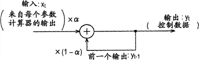
For steadiness parameter, filtering treater 42 (Fig. 1) is carried out filtration treatment to the parameter of the parameter calculator from parameter generator 17 (face orientation parameter calculator 43, face location parameter calculator 44, eyes closed ratio parameter counter 45, face open ratio parameter counter 46 and smile facial parameter counter 47) output.
The filtration treatment of filtering treater 42 is described below with reference to Fig. 7 A and 7B.
y
t=αxx
t+(1-α)xy
t-1 …(1)
In equation (1), α means parameter x
tWith parameter y
T-1Between additional rate (addition ratio), and parameter y
T-1It is previous (immediately preceding) parameter by filtering treater 42 outputs.
The function meaned according to the maximal value max by as shown in Fig. 7 B and two threshold value thresA and thresB come from variable diff (=| curr-prev|) calculate additional rate α, variable diff is the absolute value of the difference of current input value and previous input value.The function of determining additional rate α is increasing with constant gradient to the variable diff of threshold value thresA from zero, in the variable diff from threshold value thresA to threshold value thresB, flatten with maximal value max, and descend from threshold value thresB with the opposite constant gradient of the gradient with from zero to the variable diff of threshold value thresA.If threshold value thresA and threshold value thresB are equal to each other, determine that the function of additional rate α has if incited somebody to action described chevron in the back.
In filtering treater 42, set maximal value max, threshold value thresA and threshold value thresB.Filtering treater 42 is according to from variable diff and the definite additional rate α of aforesaid equation (1), the parameter from the parameter calculator input being carried out to filtration treatment.Then, the parameter of filtering treater 42 after processing after filtration is fed to image generator 18.
Face orientation parameter calculator 43 (Fig. 1) calculates the parameter of face's angle of controlling the incarnation produced by image generator 18 according to face's angle of the user who is revised by face orientation correction processor 41.
Face orientation correction processor 41 is carried out correcting process in right-hand coordinate system, and image generator 18 is carried out its processing in coordinate system leftward.With reference to Fig. 8 A, unify left-handed coordinate system system of right-handed coordinate system is opposite mutually on rotational action and deflection action.Therefore, the symbol of the direction of 43 pairs of rotational action by face's angle of the user of face orientation correction processor 41 corrections of face orientation parameter calculator and deflection action reverses.
According to the function as shown in Fig. 8 B, face orientation parameter calculator 43 calculates y=x-p, and x means user's input face angle, and y means the output face angle of incarnation.Here, p means the off-set value for the initial value of face orientation.In standard state, the default value of p is zero (def=0.0).
Parameter by face's angle of the incarnation of face orientation parameter calculator 43 output is supplied to filtering treater 42.42 pairs of parameters as shown in Figure 7A of filtering treater are carried out filtration treatment.By the function that the maximal value max=1.0 by as shown in Fig. 8 C, threshold value thresA=0.1 π and threshold value thresB=0.2 π mean, determine the additional rate α in the filtration treatment that is used in filtering treater 42.
According to reference point, horizontal width and the vertical length (X of face, the Y of face, the W of face, the H of face) that are included in the face detection object information of filtering treater 42 outputs, face location parameter calculator 44 (Fig. 1) calculates the parameter of the face location of controlling the incarnation produced by image generator 18.
As shown in Figure 3, the upper left corner of face area is set to the reference point in the face detection object information of face detection processor 32 outputs, and shown in Fig. 9 A, the center of face area is set as reference point (the alphabetical x indication in Fig. 9 A) by image generator 18.Face recognition controller 31 serves as its processing of the middle execution of coordinate system (Fig. 3) of initial point (0,0) in the upper left corner with whole image.Image generator 18 is usingd the center of whole image and is carried out its processing as initial point (0,0), as shown in Fig. 9 A.
Face location parameter calculator 44 calculates the function as shown in Fig. 9 B, that is, following equation (2), thus will as the coordinate of the central point of the face area in the coordinate system of initial point, be defined as the parameter of face location usining the center of whole image.
In equation (2), x
InAnd y
InExpression is input to the reference point of the face area of face location parameter calculator 44,, is included in the XY coordinate (X of face, the Y of face) of the reference point of the face area in the face detection object information of face detection processor 32 outputs that is.In addition, w
InAnd h
InExpression is input to horizontal width and the vertical length (W of face, the H of face) of the face area of face location parameter calculator 44 respectively.In addition, x
outAnd y
outExpression is by the parameter (the XY coordinate of the point that the alphabetical x in Fig. 9 A means) of the face area of face location parameter calculator 44 outputs.Here, x
In, y
In, w
InAnd h
InBe to using the upper left corner of whole image as the value in the normalized coordinate system of initial point (0,0), and fall in from 0.0 to 0.1 scope x
outAnd y
outBe to using the center of whole image as the value in the normalized coordinate system of initial point (0,0), and fall in from-0.1 to 0.1 scope.
Parameter by the face location of face location parameter calculator 44 output is supplied to filtering treater 42.Then, 42 pairs of parameters as shown in Figure 7A of filtering treater are carried out filtration treatment.According to the function that the maximal value max=0.8 by as shown in Figure 9 C and threshold value thresA=threshold value thresB=0.8 mean, determine the additional rate α in the filtration treatment that is used in filtering treater 42.Because threshold value thresA equals threshold value thresB, determine that the function of additional rate α has the class chevron.Note, the class mountain function is more stable than trapezoidal function.
Based on the user's who is determined by attribute determiner 34 right eye, open mark and left eye opens mark, eyes closed ratio parameter counter 45 (Fig. 1) calculates the parameter of the closed ratio of the right eye of controlling the incarnation produced by image generator 18 and the closed ratio of left eye.
Eyes closed ratio parameter counter 45 is calculated as follows equation (3) based on sigmoid function (sigmoid function).Thus, eyes closed ratio parameter counter 45 calculates the closed ratio of right eye of incarnation and the parameter of the closed ratio of left eye from user's right eye and the mark that opens of left eye.
In equation (3), y is closed ratio, and x opens mark, and ofs is the value that departs from the initial value that opens mark, and grad is the value of setting the gentle degree (mildness) of sigmoid function.The value span of being calculated by sigmoid function, from 0.0 to 1.0, gain being amplification factor, is amplified this value according to amplification factor about central value (0.5).
Figure 10 A show by use a plurality of grad values (0.2-0.6) with and 1.4 amplification factor gain calculate the closed ratio y that sigmoid function determines and open the relation between mark x.Here, p is the peaked value of opening mark that can be set to for user's right eye and left eye.In standard state, 6.75 maximum default value (def=6.75) is set for for opening mark, and the maximum default value is set as to 6.75 (def=6.75).In addition, 0.4 default value is set for the value grad for standard state, and default value is set as to 0.4.Maximal value and minimum value can be set for the parameter for closed ratio, can set maximal value and minimum value.With reference to Figure 10 A, 1.0 are set for maximal value and are set for minimum value 0.0 1.0.
Use sigmoid function, the user's who is determined by attribute determiner 34 right eye and left eye open the parameter that mark is converted into the closed ratio of the right eye of the incarnation that will be produced by image generator 18 and left eye.In this mode, in the situation that the independent variation of eyes in all opening the size of eyes be reduced, face orientation is controlled the closed ratio of eyes and the impact of opening ratio.For example, the people of blink (narrow-eyed) trends towards having the low mark that opens, and the people has the low mark that opens when looking down.If use sigmoid function to determine the parameter of closed ratio, this trend is controlled.
The use of sigmoid function not only allow to present eyes at open configuration and the another eyes at closure state (nictation), also allow naturally to present the eyes of semi-closure.The opening and closing of eyes can be presented, the action that makes eyelid eyes open or eyes closed to start be gentle.Substitute sigmoid function, make the parameter of closed ratio changes linearly between maximal value and minimum value function can be used for presenting blink.Yet the use of sigmoid function is more near the lose face opening and closing of eyeball of people's actual act earth's surface.
Parameter by the closed ratio of the right eye of eyes closed ratio parameter counter 45 output and left eye is supplied to filtering treater 42.42 pairs of parameters as shown in Figure 7A of filtering treater are carried out filtration treatment.By the function that the maximal value max=0.8 by as shown in Figure 10 B and threshold value thresA=threshold value thresB=0.8 mean, determine the additional rate α in the filtration treatment that is used in filtering treater 42.
Face opens 14 points of ratio parameter counter 46 (Fig. 1) based on the profile of the discriminating user's who is detected by part detail detector 35 face, calculates the parameter of opening ratio of the face of the incarnation that control will produce by image generator 18.
Before calculating parameter, face opens ratio parameter counter 46 to be carried out two evaluation process and with each of the profile of the face according to differentiating the user, puts to determine whether the testing result of profile of face is correct.
In the first evaluation process, use the distance on vertical direction between predetermined point.For example, face opens ratio parameter counter 46 and determines the vertical range (R1, R2 and R3) between any two neighbor points of four points in the right except rightmost point in 14 points of profile of face of the discriminating users as shown in the left half of Figure 11 A.Similarly, face opens ratio parameter counter 46 and determines the vertical range (C1, C2 and C3) between any two neighbor points of vertical range (L1, L2 and L3) between any two neighbor points of four points in the left side except Far Left point and four points in center.If all vertical ranges of determining like this be on the occasion of, face opens ratio parameter counter 46 and determines that the testing result of the profile of faces is correct.
In the second evaluation process, make the shape of two predetermined points as the rectangular area at diagonal angle.For example, face opens ratio parameter counter 46 and determines and using any two neighbor points of lower three points in 14 points of the profile of the user of definition as shown in the right half of Figure 11 A face, in upper lip as the shape of De De rectangular area, diagonal angle (T1 and T2).Similarly, face open ratio parameter counter 46 determine using in 14 points of profile of the face that defines the user, in any two neighbor points of upper three points of lower lip shape as De De rectangular area, diagonal angle (T3 and T4).If all rectangular areas of determining thus are horizontally extending, face opens ratio parameter counter 46 and determines that the testing result of face profiles is correct.
The testing result of face profile is correct if determine in the first and second evaluation process, and face opens ratio parameter counter 46 and based on 14 points of the face profile of differentiating the user who is detected by part detail detector 35, calculates the parameter of opening ratio of the incarnation that will be produced by image generator 18.If the testing result of face profile is correct, user's face opens in the face that is reflected in incarnation.
(distance C 2: the function (y=(1/p) x-0.1) that ratio parameter counter 46 calculates is as shown in Figure 11 B opened in the input height in Figure 11 A), face in response to the distance between the central point of the upside of the central point of the downside of upper lip and lower lip.Face opens the face that ratio parameter counter 46 calculates thus as parameter and opens ratio.In equation (y=(1/p) x-0.1), x is the vertical range (highly) as input value, and y opens the parameter of ratio as face, and p is the value of setting as the maximum normal distance (highly) of input value.In standard state, 0.09 is set the default value (def=0.09) as p, and the maximal value of p is 0.19.Show that the parameter that face opens ratio is set and is mapped to linearly height in the standard state that face all opens.
For calculating, show that the distance that face opens the parameter of ratio can determine according to the distance between the center of the center of face and nose.In this case, by the distance between the center of the center by face and nose, be multiplied by 0.4 resulting value and be used as above-mentioned input value (highly).
The parameter that face opens ratio that shows of being opened ratio parameter counter 46 output by face is supplied to filtering treater 42, then to the filtration treatment shown in parameter execution graph 7A.According to the function that the maximal value max=0.8 by shown in Figure 11 C and threshold value thresA=threshold value thresB=0.8 mean, determine the additional rate α in the filtration treatment that is used in filtering treater 42.
Smile facial parameter counter 47 (Fig. 1) calculates the parameter of control by the smile ratio of the incarnation of image generator 18 generations based on the smile mark be included in the attribute information of attribute determiner 34 outputs.
The smile mark detected by attribute determiner 34 is that span is from 0 to 70 value.Smile facial parameter counter 47 calculates by the function (y=(1/50) x-0.4) calculated as shown in Figure 12 A the parameter that shows the smile mark.In the equation of function, x means the smile mark as input value, and y means as the parameter that shows the output valve of smile ratio.
The parameter that shows the smile ratio of being exported by smile facial parameter counter 47 is supplied to filtering treater 42.The filtration treatment that filtering treater 42 is carried out as shown in Figure 7A.According to the function that the maximal value max=0.8 by shown in Figure 12 B and threshold value thresA=threshold value thresB=0.8 mean, determine the additional rate α in the filtration treatment that is used in filtering treater 42.
The parameter that parameter calculator in parameter generator 17 produces is supplied to image generator 18 (Fig. 1) and image generator 18 produces incarnation based on parameter.
Image generator 18 comprises three-dimensional (3D) data management system 51, tinter (shader) manager 52, renderer (renderer) 53 and synthesis processor 54.
The 3D data of 3D data management system 51 management incarnation, that is, and the database (not shown) of the 3D data of the managed storage male sex, women and children's incarnation.3D data management system 51 receives model informations (showing about the face image it is the information of the male sex, the women's or children's definite result) from Model Selection device 16.In response to the model information from database, 3D data management system 51 reads the 3D data of incarnation, and the 3D data that then will read are fed to renderer 53.
The various data of 3D data management system 51 management, these data be take the coordinate conversion of 3D model as output (two dimension) image and carry out texture processing with for texture being given to the bonding texture in surface of (impart) 3D model for carrying out geometric manipulations.Then, 3D data management system 51 is fed to renderer 53 by various data.
When renderer 53 is played up the 3D data, the painted processing of tinter manager 52 management.In painted processing, tinter manager 52 is carried out calculating operation and is carried out painted 3D data with the light source (illumination) with predetermined.Tinter manager 52 is fed to renderer 53 by the result of calculation of painted processing.
Renderer 53 (shows the parameter that the right eye of incarnation and each the eyes in left eye open ratio according to the expression parameter of the output of the parameter calculator in parameter generator 17, show the parameter of the smile ratio of incarnation, and show that the face of incarnation opens the parameter of ratio) come by carrying out and play up processing by the 3D transformation of data (morph) of 3D data management system 51 supplies.
3D data management system 51 will be fed to renderer 53 for the 3D data of a plurality of basic facial expressions of single model.For example, 3D data management system 51 to renderer 53 for each expressionless 3D data, the 3D data of right eye closure, the 3D data of left eye closure, the 3D data of smile face, the 3D data that face opens that are applied to male sex's model, Female Model and children's model, as shown in Figure 13.
Renderer 53 is weighted summation with corresponding parameter by the summit of basic facial expression 3D data, thereby determines each summit of the 3D data that will play up.The predetermined summit P of the 3D data that more particularly, play up
Synth(x, y, z) is P
Synth(x, y, z)=P
Reye_close(x, y, z) W
Reye_close+ P
Leye_close(x, y, z) W
Leye_close+ P
Mouth_open(x, y, z) W
Mouth_open+ P
Smile(x, y, z) W
Smile+ P
Normal(x, y, z) (1-W
Reye_close-W
Leye_close-W
Smile-W
Mouth_open).In this equation, P
Reye_close(x, y, z) means the predetermined summit of the 3D data of right eye closure, W
Reye_closeThe parameter that shows the eyes closed ratio of right eye, P
Leye_close(x, y, z) means the predetermined summit of the 3D data of left eye closure, W
Leye_closeThe parameter that shows the eyes closed ratio of left eye, P
Mouth_open(x, y, z) means the predetermined summit of the 3D data that face opens, W
Mouth_openShow that the face of incarnation opens the parameter of ratio, P
Smile(x, y, z) means the predetermined summit of the 3D data of smiling, W
SmileThe parameter that shows the smile ratio of incarnation, and P
Normal(x, y, z) means the predetermined summit of expressionless 3D data.
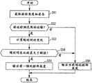
Figure 14 shows the process flow diagram of the image processing process of being carried out by the image processing apparatus 11 shown in Fig. 1.
In step S12, face detection processor 32 is carried out face detection and is processed the face area with the face of the image detection user from being supplied in step S11 by Camiera input unit 14.Once face area being detected, face detection processor 32 output face detection object informations.
Processing advances to step S13 from step S12.Face recognition controller 31 determines whether face detection processor 32 detects face area in step S12,, determine whether face detection processor 32 has exported the face detection object information that is.
If face recognition controller 31 determines that in step S13 face detection processor 32 does not detect face area, processes and turns back to step S11.Repeating step S11 and step S12.If face recognition controller 31 determines that in step S13 face detection processor 32 has detected face area, processes and advances to step S14.
In step S14, part detecting device 33 detects the part of face from the face area shown by the face detection object information, and this face detection object information is exported in step S12 by face detection processor 32.Part detecting device 33 output shows each the partial information of coordinate at center in the part that comprises right eye, left eye, nose and face, and shows from the position of the face that this part is determined and the face location information of attitude.Processing advances to step S15.
In step S15, attribute determiner 34 is determined the attribute of the face of the user in face area based on the partial information of being exported in step S14 by part detecting device 33, and output shows the attribute information of determining result.As previously described, attribute information comprises male sex's mark and adult mark.
Processing advances to step S16 from step S15.Face recognition controller 31 determines whether the face area as current processing target is new face area.Image processing apparatus 11 is processed from the image of camera 12 inputs on the basis of each frame.If the frame detected for the first time from the face area as current processing target is 15 or still less, face recognition controller 31 determines that the face area as current processing target is fresh target to the quantity of the frame of former frame detected among step S12.If the quantity of frame is more than 15, face recognition controller 31 determines that the face area as current processing target is not fresh target so.
If face recognition controller 31 determines that in step S16 the face area as current processing target is fresh target, processes and advances to step S17.
In step S17, face recognition controller 31 is included in male sex's mark and the adult mark in the attribute information of being exported in step S15 by attribute determiner 34 to 16 supplies of Model Selection device.Processing advances to step S18.
In step S18, Model Selection device 16 comes execution model to select to process based on male sex's mark of being supplied in step S17 by face recognition controller 31 and adult mark.In Model Selection was processed, the data of the 3D as incarnation in Model Selection device 16 selection male sex models, Female Model and children's model were to replace the face of user in face area.Back is selected to process with reference to Figure 15 descriptive model.After Model Selection in step S18 is processed, process and turn back to step S11.Then, next frame is repeated to same treatment as above.
If face recognition controller 31 determines that in step S16 the face area as current processing target is not fresh target, processes and advances to step S19 so.
In step S19, part detail detector 35 detects the point (seeing Fig. 5 A and 5B) of the part of differentiating in detail user's face in face area.Part detail detector 35 output object informations.Processing advances to step S20.
In step S20, face orientation correction processor 41 is carried out the orientation of face orientation correcting process with the face of the user in the correction face area.The face orientation correcting process is described with reference to Figure 16 in back.After the face orientation correcting process, process and advance to step S21.
In step S21, each parameter calculator in parameter generator 17 calculates corresponding parameter.More particularly, face orientation parameter calculator 43 calculates the parameter of the face's angle that shows incarnation from face's angle of the user that exported in step S20 by face orientation correction processor 41.Face location parameter calculator 44 calculates the parameter of the face location that shows incarnation from the face detection object information of being exported in step S12 by face recognition controller 31.
In addition, eyes closed ratio parameter counter 45 opens mark from the eyes of the user's that determined in step S15 by attribute determiner 34 right eye and left eye and calculates the right eye of incarnation and the eyes closed ratio of left eye.Face opens ratio parameter counter 46 and calculates from 14 points of the profile of the face of differentiating the user who is detected by part detail detector 35 in step S19 the parameter that the face that shows incarnation opens ratio.The smile mark of smile facial parameter counter 47 from be included in the attribute information of being exported by attribute determiner 34 in step S15 calculates the parameter of the smile ratio that shows incarnation.
In step S22, filtering treater 42 is carried out filtration treatment so that parameter stability to the parameter of being opened ratio parameter counter 46 and 47 outputs of smile facial parameter counter by face orientation parameter calculator 43, face location parameter calculator 44, eyes closed ratio parameter counter 45, face respectively.Then, filtering treater 42 will be outputed to image generator 18 by stable parameter through filtration treatment.
In step S23, image generator 18 carries out image produce processes the image that will show on display 13 to produce.
More particularly, the 3D data management system in image generator 18 51 is supplied to the 3D data of five expressions of incarnation the face of renderer 53 with the user in replacing face area according to the model information by Model Selection device 16 output in the Model Selection of step S18 is processed.In response to the parameter by filtering treater 42 supplies, renderer 53 produces the image of incarnation by the 3D data of being out of shape five expressions.The image of the incarnation that the position synthesis of the user of synthesis processor 54 in the image of being taken by camera 12 face is played up by renderer 53.Thus, synthesis processor 54 produces the image that users' face is replaced by incarnation.After image produces processing, process and advance to step S24.
In step S24, image generator 18 is fed to display 13 by the image produced in step S23, and display 13 shows image.Processing turns back to step S11.Next frame is repeated to same treatment as above.
Because the incarnation of the attributes match with the user is automatically shown, so image processing apparatus 11 has been saved user's the time that is used to specify incarnation.In the prior art, in order to show the incarnation of replacing user face, the incarnation of user's appointment and user's attributes match.By comparison, image processing apparatus 11 has been saved such time, and when basically with user's image, being taken by camera 12, makes to be presented on display 13 with the incarnation of user's attributes match.Thus, the user can feel the one sense with incarnation.For example, when image processing apparatus 11 is used in Virtual Space, for example play games or chatroom in, the user finds more easily to be shifted one's love in Virtual Space.
Because each parameter is filtered processing, it is level and smooth that the action of incarnation becomes.The user feels and incarnation one more.For example, the error of several pixels is allowed in the face detection of the face for detection of in image is processed.If face keeps motionless (or slowly mobile), due to error, incarnation is (or fluctuation at high speed in slight the swing) vibration in position.In this case, filtration treatment prevents the incarnation vibration, and exempts user (people who watches image or play games in Virtual Space) is caused by such vibration when there is no filtration treatment sense of discomfort.
As described in reference Fig. 7 A to 7B, dynamically determine additional rate α based on the variable diff between current input value and previous input value.Be suitable for keeping the filtration treatment of the face of the face of motionless (or slowly mobile) and fast moving to be performed.More particularly, when face keeps motionless, in order to stablize the position of face, the value of additional rate α is set to little (that is, previous output valve (parameter y
T-1) weight be set to large and input value (parameter x
t) weight be set to little).When face's fast moving, in order to increase the trace performance of the movement that responds face, the value of additional rate α is set to greatly.Thus, incarnation is displayed on position more accurately.If face moves rapidly, the error related in face detection is processed is with respect to the travel distance of the face less that becomes.The vibration of above-mentioned incarnation more can not noted.Thus, filtration treatment provides visual effect intuitively to the user.
Because expression is synthesized in order to play up based on the expression parameter produced by parameter generator 17, incarnation can have than more expressive face in the past.The image processing apparatus 11 of carries out image processing process provides the new experience of virtual communication in Virtual Space and abundant in content communication aspects to the user.
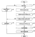
Figure 15 shows the process flow diagram that the Model Selection in the step S18 of Figure 14 is processed.
In step S31,16 initialization of Model Selection device are used in the count value in the Model Selection processing.Be used in Model Selection in processing be the frame count value that shows the quantity of processed frame, show that face is confirmed as children's count value of children's number of times, shows that face is confirmed as male sex's count value of the male sex's number of times, shows that face is confirmed as women's count value of women's number of times.These count values of Model Selection device 16 initialization are (for example), to zero.Processing advances to step S32.
In step S32, Model Selection device 16 determines based on the adult mark of being supplied in the step S17 of Figure 14 by face recognition controller 31 whether the face of user in face area is children.For example, if the mark of growing up for example, lower than predetermined threshold (, the grow up maximal value of mark and the intermediate value between minimum value), Model Selection device 16 determines that users' face is children.Mark is equal to or higher than predetermined threshold if grow up, and Model Selection device 16 determines that the face of user in face area grows up.
If Model Selection device 16 determines that in step S32 the face of user in face area is children, process and advance to step S33.Model Selection device 16 adds 1 by children's count value.
On the other hand, if Model Selection device 16 determines that in step S32 the face of user in face area is not children, process and advance to step S34.
In step S34, Model Selection device 16 determines based on the male sex's mark by 31 supplies of face recognition controller whether the face of user in face area is the male sex.For example, for example, if male sex's mark is equal to or higher than predetermined threshold (, the grow up maximal value of mark and the intermediate value between minimum value), Model Selection device 16 determines that user's face is the male sex.If male sex's mark is lower than predetermined threshold, Model Selection device 16 determines that the face of user in face area is not the male sex so.
If Model Selection device 16 determines that in step S34 the face of user in face area is the male sex, process and advance to step S35 so.Model Selection device 16 adds 1 by male sex's count value.On the other hand, if Model Selection device 16 determines that in step S34 the face of user in face area is not the male sex, process and advance to step S36 so.Model Selection device 16 adds 1 by women's count value.
After one of them of step S33, S35 and S36, process and advance to step S37.Model Selection device 16 determines whether frame count value is equal to or higher than the preset count (for example, 15) of setting for Model Selection.
If Model Selection device 16 is determined frame count value in step S37 be not to be equal to or higher than the preset count (lower than preset count) of setting for Model Selection, process and advance to step S38.In step S38, Model Selection device 16 adds 1 by frame count value.Processing turns back to step S32.Next frame is repeated to same treatment as above.
If Model Selection device 16 determines that in step S37 frame count value is equal to or higher than the preset count of setting for Model Selection, process and advance to step S39 so.
In step S39, Model Selection device 16 with reference to children's count value, male sex's count value and women's count value in order to select in children, masculinity and femininity to have the highest model of the data of the 3D as incarnation of fixed number (the highest count value) really.
Processing advances to step S40 from step S39.Model Selection device 16 will show that the information supply of the selection result in step S39 is to image generator 18.Thus, processing finishes.
Figure 16 is the process flow diagram of face orientation correcting process in the step S20 of Figure 14.
In step S51, when detected in the step S12 of face area at Figure 14, face orientation correction processor 41 is obtained the anglec of rotation (face's rotation, face's deflection) that is included in the face area in the face detection object information of face detection processor 32 outputs, and obtains the attitude (posture rotation, posture deflection) that is included in the face area in the face location information of being exported by part detecting device 33 in step S14.
Processing advances to step S52 from step S51.Whether the orientation that face orientation correction processor 41 is determined user face in face area is near the edge of sensing range.
The edge of sensing range neighbouring by with the face detection object information in the ratio of sensing range define.Near the ratio at the edge of definition sensing range is predefined in face orientation correction processor 41.For example, near the ratio at the edge of sensing range can be set to 87.5%.If the anglec of rotation of face area (face rotate, face's deflection) is greater than 87.5% of sensing range in the face detection object information, the orientation of determining user's face is near the edge of sensing range.
In the face detection object information, the sensing range of the rotational action of face can be that approximately ± 20 are spent as shown in Figure 6.If the anglec of rotation of face area (face's rotation) is greater than approximately ± 17.5, face orientation correction processor 41 determines that the orientation of users' face is near the edge of sensing range.Similarly, in the face detection object information, the sensing range of the deflection action of face can be about ± 35 degree.If the anglec of rotation of face area (face's deflection) is greater than approximately ± 30.6 degree, face orientation correction processor 41 determines that the orientation of users' face is near the edge of sensing range.In this mode, face orientation correction processor 41 determine the orientation of users' face be whether the sensing range in each of the deflection action of face and rotational action edge near.If the face detection object information for pitching action is also available, face orientation correction processor 41 determines that in similar processing whether the orientation of user's face is near the edge of sensing range.
In this mode, near the of the edge of sensing range defines by the ratio with sensing range.Alternatively, near the edge of sensing range can be directly by angle define (for example, can be defined by edge 3 degree of distance sensing range sensing range edge near).The sensing range of the orientation of user's face is not limited to scope listed in Fig. 6, and can be depending on the performance of detecting device (or the face detection dictionary used by detecting device) of use and different.For example, detecting device can have for rotational action for ± 40 degree, for pitching action for ± 20 degree with for the sensing ranges of deflection action for ± 45 degree, and other detecting device can have for rotational action for ± 90 degree, for the pitching action for ± 45 degree with for the sensing ranges of deflection action for ± 45 degree.
If it is near the edge of sensing range that face orientation correction processor 41 is determined the orientation of user's face in face area, processes and advance to step S53.Face orientation correction processor 41 is calculated the anglec of rotation of face area and the time of attitude changes.
Face orientation correction processor 41 is stored in the anglec of rotation of the face area of exporting in the processing of former frame and the attitude of face area, and the time of calculating between former frame and present frame changes.More particularly, the time of the anglec of rotation of face area changes diff
tgt(=| tgtIn
t-tgtIn
T-1|) be determined tgtIn wherein
tMean current face angle, and tgtIn
T-1The face's angle that means former frame.In addition, the time of the attitude of current face area changes diff
pos(=| posIn
t-posIn
T-1|) be determined posIn wherein
tMean current face angle, and posIn
T-1The face's angle that means former frame.
Processing advances to step S54 from step S53.Between time of calculating in face orientation correction processor 41 determining step S54 changes poor (=| diff
tgt-diff
pos|) whether be greater than predetermined threshold.
If face orientation correction processor 41 is determined the poor predetermined threshold that is greater than in step S54, process and advance to step S55.Angle (the posIn of face of face orientation correction processor 41 output former frame
T-1), and finish thus the face orientation correcting process.Because causing the large time, noise changes, so in order to control the vibration of incarnation, the angle (posIn of face of face orientation correction processor 41 output former frame
T-1) replace the current angle (posIn of face suffer this large variation
t).
Face orientation correction processor 41 can be determined user's face in face area in step S52 orientation not near the edge of sensing range (for example, sensing range as above 87.5% in), or face orientation correction processor 41 can determine in step S54 that the difference of time between changing is not more than predetermined threshold (time change be less than predetermined threshold).In this case, process and advance to step S56.
In step S56, the angle (posIn of face of face orientation correction processor 41 output present frames
t).Thus, finish the face orientation correcting process.In this case, the orientation of user's face, not near the edge of sensing range, and is determined and face's angle accurately detected.The time variation is little, and does not have noise to produce.Angle (the posIn of face of face orientation correction processor 41 output present frames
t).
Even during near the edge that is oriented in sensing range of user's face, the face orientation correcting process also can stop testing result to change brokenly.The face of incarnation is avoided near the factitious vibration edge of sensing range.Thus, incarnation can be followed the movement of user's face exactly.
According to the present embodiment, use the expression parameter of discussing with reference to Figure 13 to synthesize the expression of incarnation.Except those expression parameters, more multiparameter can be used as for the synthetic parameter of the expression of incarnation.
Figure 17 shows the example that can be used on the parameter in synthesizing of expressing one's feelings.With reference to Figure 17, available parameter type comprises emotion parameter, partial parameters and lip (viseme) parameter in expression is synthetic.
Except the smile parameter that the smile mark from being included in the attribute information of attribute determiner 34 outputs is determined, the emotion parameter also comprises the determined sad parameter of use attribute determiner 34 and angry parameter.
Partial parameters comprises from definite parameter nictation of 55 points (seeing Fig. 5 A) by 35 outputs of part detail detector, eyebrow parameter, eyeball parameter and face closure and opens parameter.
The lip parameter comprises from the vowel of vowel lip determiner 62 outputs of Figure 18 A that will be discussed by back and 18B determines the definite lip of mark/a/ parameter, lip/i/ parameter, lip/u/ parameter, lip/e/ parameter, lip/o/ parameter and lip/n/ parameter.By based on these lip parameters, synthesizing the mouth shape of incarnation, the action of user's face verily is reflected in incarnation.
The synthetic processing of mouth shape of synthesizing the mouth shape of incarnation based on the lip parameter described below with reference to Figure 18 A and 18B.
The basic mouth shape of image processing apparatus 11 each vowel of storage is to synthesize mouth shape.More particularly, for the basic mouth shape of sending out vowel/a/, vowel/i/, vowel/u/, vowel/e/, vowel/o/ and vowel/n/, be stored, as shown in Figure 18 A.Here, pronunciation/n/ comprises pronunciation/p/.
Lip parameter W based on the vowel/a/ of the weight as each basic configuration
a, vowel/i/ lip parameter W
i, vowel/u/ lip parameter W
u, vowel/e/ lip parameter W
e, vowel/o/ lip parameter W
oAnd the lip parameter W of vowel/n/
nSynthesize mouth shape.The action of user's face more verily is reflected in incarnation.
With reference to Figure 18 B, produce for sending out the basic configuration of vowel/e/ by synthetic basic configuration for vowel/i/ with for the basic configuration of sending out vowel/a/.By synthetic basic configuration for vowel/u/ with for the basic configuration of sending out vowel/a/, produce for sending out the basic configuration of vowel/o/.
Lip parameter W with the vowel/a/ of the weight of serving as basic configuration
a, vowel/i/ lip parameter W
i, vowel/u/ lip parameter W
uAnd the lip parameter W of vowel/n/
nSynthesize mouth shape.With the same way as with as shown in Figure 18 A, the action of user's face verily is reflected in incarnation.Through these, process, the quantity that is used in the parameter in mouth shape synthetic is reduced, and processing itself is simplified.The quantity of the basic configuration of the vowel of storing also is reduced.
From discriminating, determine the lip parameter by the point of the profile of the face of part detail detector 35 detections.Also can determine the lip parameter through speech recognition.
Figure 19 shows the block diagram of mouth shape synthesis processor 61 that synthesizes the mouth shape of incarnation according to the lip parameter.
Mouth shape synthesis processor 61 shown in Figure 19 comprises vowel lip determiner 62, speech recognition vowel determiner 63, lip parameter determiner 64, mouth shape model database 65 and mouth shape compositor 66.
The voice that speech recognition vowel determiner 63 receives by the input of the voice-input device (not shown) such as microphone.Voice recognition processing carried out in 63 pairs of voice of speech recognition vowel determiner, thereby determine the vowel sent by the user, and vowel is determined to mark is fed to lip parameter determiner 64.
As described as reference Figure 18 A and 18B, 65 storages of mouth shape model database are for the 3D data of the basic mouth shape of each vowel.Mouth shape compositor 66 is weighted summation with each lip parameter of vowel to the summit of the 3D data for basic mouth shape, thus synthetic mouth shape.
The mouth shape of mouth shape synthesis processor 61 synthetic incarnation, renderer 53 is played up the 3D data of mouth shape.Thus, the shape of the face of incarnation is closer to the shape of user's face.The incarnation produced can be spoken with more being similar to the speak attitude of attitude of user.Due to the mouth shape of the incarnation mouth shape close to the user, so the user feels the one sense with incarnation.The user feels the image be presented on display 13 is more easily shifted one's love.
The Model Selection parameter comprises age parameter, sex parameter and plants family parameter.Other parameters comprise the glasses parameter.Based on the attribute of being determined by attribute determiner 34, determine parameter.
The age parameter has shown that the parameter with the age bracket that is presented at the face in image is (by the age bracket of age description, tens, twenties, thirties age group for example, or the rough age group of describing, for example children (0-tens), adult (twenties-fifties), old (sixties or older)).Attribute determiner 34 is determined the attribute of the face shown in image, and output means the mark of the numerical value evaluation (numerical rating) of the degree of growing up, children's degree and old degree.Rely on this mark, determine the age parameter.3D data management system 51 will be fed to renderer 53 based on the 3D data of the incarnation of age parameter.Than simple classification for grow up or children more shown near the incarnation at age of user.
The sex parameter list obviously is shown in the sex (sex) of the face in image.
Race's parameter shows the race (such as white race, black race or the yellow race) of the face shown in image.Attribute determiner 34 is determined the attribute of the face shown in image, and output means the mark of the numerical value evaluation of each ethnic degree.Based on mark, determine kind of a family parameter.Ethnic texture and 3D data that 3D data management system 51 will be planted family parameter are fed to renderer 53.Thus, more shown as the incarnation of user's face.
The glasses parameter shows in the face of shown image whether wear glasses.34 outputs of attribute determiner mean the mark of the numerical value evaluation of the degree of whether wearing glasses in the face of the image shown.According to mark, determine the glasses parameter.If the glasses parameter shows, wear glasses, 3D data management system 41 is fed to renderer 53 by the 3D data of glasses.The incarnation of wearing glasses is automatically shown.
According to the present embodiment, carry out automatically preference pattern according to user's attribute (children, the male sex, women).If identify the user by the user is accurately carried out to face recognition, user's face can be replaced by the incarnation by user's pre-registration.If the user is passed through face recognition and differentiated individually, the user can avoid the incarnation of designated user oneself.Thus, the user will enjoy real space and Virtual Space (being presented at the space of the image on display 13) in seamless mode.
Attribute by the definite user of image processing apparatus 11 is not to comprise all above-mentioned parameters.If it is also enough that attribute comprises one of above-mentioned parameter.
Error and the parameter of being exported by parameter calculator suffer variation sharply even occur in the calculating of hope parameter calculator in parameter generator 17, and filtration treatment also can be eliminated the impact of error and make the behavior of incarnation avoid postponing.
Key concept with reference to the filtration treatment of the hope of Figure 21 characterising parameter generator 17.The parameter of parameter calculator in parameter generator 17 (that is, face orientation parameter calculator 43, face location parameter calculator 44, eyes closed ratio parameter counter 45, face open ratio parameter counter 46 and smile facial parameter counter 47) output is based on user's the estimated result (orientation of face, the position of face, eyes closed and open the closed of ratio, face and open the degree of ratio and smile) of state of face of the testing result of face recognition device 15.In discussion subsequently, the parameter as processing target in filtration treatment also is known as the state estimation end value.
Figure 21 shows the three types of normal distribution.In Figure 21, horizontal ordinate means the state estimation end value, and ordinate means probability.
Normal distribution curve f (x) is the state estimation end value u of center in the target as filtration treatment
fOn the error of past state estimated result value distribute.Normal distribution curve r (x) is that center is at prediction output valve u
rOn prediction output valve u
rLikelihood distribute (likelihooddistribution).From the filtration treatment result obtained before, predict with state estimation end value u
fPrediction output valve u as the filtration treatment of processing target
r.In equation below (4), use the standard deviation sigma of normal distribution curve f (x)
fStandard deviation sigma with normal distribution curve r (x)
rMean normal distribution curve f (x) and normal distribution curve r (x):
Normal distribution curve p (x) is by normal distribution curve f (x) and normal distribution curve r (x) being multiplied each other to resulting normal distribution being indicated in following equation (5):
If the state estimation end value x of usining reorganizes equation (5) as variable, normal distribution curve p (x) means by following equation (6):
In equation (6), u
pThe expectation value of normal distribution curve p (x) and the output valve of exporting in filtration treatment, σ
pThe standard deviation of normal distribution curve p (x), constant K
oIt is the standardization item (constant) of normal distribution curve p (x).Output valve u
pAnd standard deviation sigma
pBy following equation (7), mean:
In equation (7), the output valve u of filtration treatment
pVariance (=σ by the error distribution by normal distribution curve f (x) expression
f 2) with the variance (=σ of the likelihood meaned by normal distribution curve r (x)
r 2) ratio mean.
State estimation end value u as the processing target of filtration treatment
fReliability evaluated, and the reliability of assessment is reflected in the variances sigma that error distributes
f 2Variances sigma with the likelihood distribution
r 2In.Thus, filtration treatment is performed, and this filtration treatment is in response to state estimation end value u
fReliability export adaptively and state estimation end value u
fWith prediction output valve u
rRelevant value.
The variances sigma that error distributes
f 2Variances sigma with the likelihood distribution
r 2Ratio be relative value.If evaluated state estimation end value u
fReliability be reflected in variances sigma
f 2And variances sigma
r 2One of in, be also enough.According to the present embodiment, the variances sigma that error distributes
f 2Response is as the state estimation end value u of filtration treatment target
fReliability and change and the variances sigma that likelihood distributes
r 2Fixing (using predetermined fixed value).This processing is described below.
Figure 22 A-22C shows the variances sigma that error distributes
f 2In change and the output valve u of filtrator
pChange between relation.
Figure 22 A-22C shows the variances sigma distributed in error
f 2Change (σ
f=0.20,0.40 and 0.50) and the variances sigma that likelihood distributes
r 2(σ
r=0.20) normal distribution curve f (x), the normal distribution curve r (x) and the normal distribution curve p (x) that obtain fixedly the time.With reference to Figure 22 A-22C, if the variances sigma that error distributes
f 2When larger, output valve u
pMore approaching prediction output valve u becomes
rIf, the variances sigma that error distributes
f 2Output valve u hour,
pBecome more near state outcome value u
f.Variances sigma in distributing by variation error by this way
f 2, output valve u that can the adaptively modifying filtrator
p.
The variances sigma of determining that error distributes is described below
f 2Method.
By the error distribution that normal distribution curve f (x) means, serve as the state estimation end value u meaned as the filtration treatment target
fThe designator of reliability.The variances sigma distributed by error
f 2Variances sigma with the likelihood distribution
r 2Ratio determine output valve u
p.Consider this operation, if state estimation end value u
fReliability be low, by the variances sigma that error is distributed
f 2Be set as large value, if state estimation end value u
fReliability be high, by the variances sigma that error is distributed
f 2Be set as little value, it is effective that filtration treatment becomes.Thus, carry out effective filtration treatment.
For in response to state estimation end value u
fReliability and variances sigma that variation error distributes
f 2, evaluation status estimated result value u
fReliability.To evaluation status estimated result value u
fReliability can be the technology that the sampling of using history from the past output valve of filtration treatment to be used as sample changes.In this technology, use for the long-time section value with little variation, namely for long-time section, keep constant value.
The component of acceleration of state estimation end value (second differential) can be used as has the value that keeps constant character for long-time section.If consider the local time period, the goal pace component is used as having the value that keeps constant character for long-time section.The speed component of state estimation end value trends towards gradually changing in long-time section.
With reference to Figure 23 A and 23B, the relatively distribution of the speed component of the distribution of the component of acceleration of state estimation end value and state estimation end value.With reference to Figure 23 A and 23B, the component of acceleration of calculating and speed component are meaned by the sky circle, and its distribution is meaned by curve.
With reference to Figure 23 A, the component of acceleration of state estimation end value has the distribution about the variation of 0.0 symmetry, and trends towards having steady state value in long-time section.With reference to Figure 23 B, the speed component of state estimation end value does not have the distribution of the variation as symmetrical about occurrence, and does not have if in long-time section, kept the character so constant.Use for the component of acceleration of the state estimation end value of the assessment of reliability provides stable result.
According to following equation (8) from the output valve u at time t-1
p(t-1) with at the output valve u of time t-2
p(t-2) the state estimation end value u calculated at time t
f(t) component of acceleration acc (t):
acc(t)=(u
f(t)+u
p(t-2))-(2.0xu
p(t-1))…(8)
According to following equation (9) from until the state estimation end value u that the component of acceleration acc (t) of time t-1 calculates at time t
f(t) the variance var (t) of component of acceleration acc (t):
From equation (8) and (9), with the past output valve of filtrator, carry out the variance var (t) of the component of acceleration of update mode estimated result value.
The variance var (t) of the component of acceleration of the state estimation end value of upgrading based on the past output valve with filtrator and calculate mahalanobis distance (Mahalanobis ' s distance) at the component of acceleration acc (t) of the state estimation end value of time t, and mahalanobis distance square be set to the variances sigma that the error at time t distributes
f 2.More particularly, according to following equation (10), calculate the variances sigma in the error distribution of time t
f 2:
Calculate by this way at the state estimation end value u of time t as processing target
f(t) variances sigma that the error in filtration treatment distributes
f 2(t).As previously mentioned, the variances sigma of error distribution
f 2Variances sigma with the likelihood distribution
r 2Ratio be relative value, Fixed value (fixed value) is for variances sigma
r 2.
Calculate prediction output valve u
rTo determine the output valve u of the filtrator of being discussed as cf. equation (7)
p.The following describes and calculate prediction output valve u
rMethod.
From the filtration treatment result obtained so far, predict with state estimation end value u
fPrediction output valve u as the filtration treatment of processing target
r.In order to predict output valve u
r, action model is supposed.According to the present embodiment, the constant speed action model is used.The constant speed action model is based on the variation of face continuous character typically.Depend on state estimation end value u
f, that is, depend on the type of the parameter of being calculated by parameter generator 17, can use constant accelerated motion (meaning the change of the speed of face orientation).For determining state estimation end value u
fAction model can be any one in these models.
In the prediction of constant velocity model, predict current output valve based on the previous output valve in filtration treatment and previous accekeration.The prediction output valve u calculated at time t according to following equation (11)
r:
U
r(t)=u
p(t-1)+(U
p(t-1)-u
p(t-2))…(11)
From equation (11), filtrator is at time t-1 with at the past of time t-2 output valve u
p(t-1) and u
p(t-2) be used to the prediction output valve u calculated at time t
r(t).
The value of determining thus is the variance (σ distributed by the error that normal distribution curve f (x) means
f 2), the variance (σ of the likelihood that meaned by normal distribution curve r (x)
r 2) and from the prediction output valve u of the prediction of result of the filtration treatment that obtains so far
r.By calculation equation (7), the expectation value of normal distribution curve p (x), that is, and the output valve u of filtrator
pCalculated.
Figure 24 is the block diagram of filtering treater 71.
Filtering treater 71 shown in Figure 24 comprises controller 72, acceleration counter 73, acceleration variance renovator 74, mahalanobis distance counter 75, storer 76, fallout predictor 77, retainer 78 and filters counter 79.Filtering treater 71 can be used for replacing the filtering treater 42 of Fig. 1.
Controller 72 receives the parameter that each parameter calculator in parameter generator 17 calculates, that is, and and state estimation end value u
f.Each element in controller 72 controlled filter processors 71, for example, state of a control estimated result value u
fTo acceleration counter 73 and filter counter 79 supply.The state estimation end value u the following describes at time t
f(t) filtration treatment.
When acceleration counter 73 from controller 72 accepting state estimated result value u
f(t) time, acceleration counter 73 is also received in the output valve u of time t-1
p(t-1) with at the output valve u of time t-2
p(t-2).By calculation equation (8), acceleration counter 73 computing mode estimated result value u
f(t) component of acceleration acc (t), the component of acceleration acc (t) that then will calculate is fed to acceleration variance renovator 74 and mahalanobis distance counter 75.
Once from acceleration counter 73 accepting state estimated result value u
f(t) component of acceleration acc (t), acceleration variance renovator 74 calculation equations (9).Thus, the variance var (t) of the component of acceleration of acceleration variance renovator 74 computing mode estimated result values, the variance var that then will calculate (t) is fed to mahalanobis distance counter 75.
According to from the component of acceleration acc (t) of acceleration counter 73 with from the variance var (t) of the component of acceleration of acceleration variance renovator 74, the variances sigma that mahalanobis distance counter 75 (according to equation (the 10)) error of calculation distributes
f 2, the variances sigma that then will calculate
f 2Be fed to and filter counter 79.
Storer 76 storages are as the variances sigma of the likelihood distribution of fixed value
r 2, filter counter 79 and receive from storer 76 variances sigma that likelihood distributes
r 2.
Fallout predictor 77 receives output valve u from filtering treater 71
p.According to the output valve u at time t-1
p(t-1) with at the output valve u of time t-2
p(t-2), fallout predictor 77 calculation equations (11), thus calculate prediction output valve u
r(t).Then, fallout predictor 77 will be predicted output valve u
r(t) be fed to and filter counter 79.
Retainer 78 receives output valve u from filtering treater 71
p.Retainer 78 keeps output valve u
p, and by output valve u
p(t-1) and output valve u
p(t-2) be fed to acceleration counter 73.
Filter counter 79 based on the state estimation end value u by controller 72 supplies
f(t), the variances sigma that the error of being supplied by mahalanobis distance counter 75 distributes
f 2(t), the variances sigma that the likelihood of reading from storer 76 distributes
r 2(t) with by the prediction output valve u of fallout predictor 77 supply
r(t) carry out calculation equation (7).Thus, filtering counter 79 determines and exports output valve u
p(t).
Filtering treater 71 only just can evaluation status estimated result value u after the component of acceleration acc of a certain quantity (sample) is stored
fReliability.After the component of acceleration acc of predetermined quantity was stored, controller 72 was carried out to control and is processed, and made and filtered counter 79 output result of calculations.
Filtration treatment below with reference to the flow chart description filtering treater 71 of Figure 25.The filtration treatment of filtering treater 71 is performed in the step S22 of Figure 14.In the step S22 of Figure 14, as parameter (that is, state estimation end value u
f(t)) when each parameter calculator parameter generator 17 outputs to filtering treater 71, filtration treatment starts.
In step S71, controller 72 is determined the state estimation end value u of supply
f(t) whether be the new processing target of filtration treatment.
If controller 72 is determined the state estimation end value u of supply in step S71
f(t) be the new processing target of filtration treatment, process and advance to step S72.Each element in controller 72 initialization filtering treaters 71.For example, controller 72 is the built-in variable used by acceleration variance renovator 74, fallout predictor 77 and filtration counter 79 (variance var, prediction output valve u
rWith output valve u
p) be set as zero as initial value.
If controller 72 is determined the state estimation end value u of supply in step S71
f(t) not the new processing target of filtration treatment, process and advance to step S73.Controller 72 is by state estimation end value u
f(t) be fed to acceleration counter 73.Acceleration counter 73 is also from the output valve u of retainer 78 time of receptions at t-1
p(t-1) with at the output valve u of time t-2
p(t-2).Acceleration counter 73 state-based estimated result value u
f(t), output valve u
p(t-1) and output valve u
p(t-2) carry out calculation equation (8).Thus, acceleration counter 73 is determined state estimation end value u
f(t) component of acceleration acc (t) degree of will speed up component acc (t) are fed to acceleration variance renovator 74.
Processing advances to step S74 from step S73.Acceleration variance renovator 74 carrys out calculation equation (9) based on the component of acceleration acc (t) supplied in step S73 by acceleration counter 73.Thus, acceleration variance renovator 74 is determined the variance var (t) of the component of acceleration of state estimation end value.Processing advances to step S75.
In step S75, controller 72 determines whether to store the component of acceleration acc (t) of sufficient amount.Whether the quantity of the variance var (t) in other words, calculated in controller 72 determining step S74 is even as big as evaluation status estimated result value u
fReliability, this variance var (t) is according to state estimation end value u
fQuantity determine.More particularly, from the definite variance var (t) of the component of acceleration acc (t) of a certain quantity, be used to evaluation status estimated result value u
fReliability.It is threshold value (for example, 20) that controller 72 is set a certain quantity.If acceleration variance renovator 74 uses to calculate the quantity of the component of acceleration acc (t) of variance var (t) and is equal to or greater than threshold value, controller 72 determines that the component of acceleration acc (t) of sufficient amounts is stored.On the other hand, be less than threshold value if acceleration variance renovator 74 uses to calculate the quantity of the component of acceleration acc (t) of variance var (t), controller 72 is determined the component of acceleration acc (t) that does not store sufficient amount.
Due to the output valve u supplied at time t-2 by retainer 78 in step S73
p(t-2) be used, so the state estimation end value u supplied is determined in contrast in step S73-S75
f(output valve u while (t) being new processing target
pWhile (t-2) being output) image of late two frames carries out and processes.Owing in step S71, determining state estimation end value u
f(t) be fresh target, thus skips steps S73 and S75 execution step S76, until two frames are output.
After step S72, or controller 72 determines do not have the component of acceleration acc (t) of sufficient amount to be stored in step S75, processes and advances to step S76.In step S76, the state estimation end value u of controller 72 output supplies
f(t) as the output valve u to fallout predictor 77 and retainer 78
p(t).Due to state estimation end value u
f(t) reliability is not assessed exactly, so filtering treater 71 does not calculate output valve u
p.After step S76, filtration treatment finishes thus.Then, next frame is processed.
If controller 72 is determined the component of acceleration acc (t) of sufficient amount and is stored, processes and advance to step S77 in step S75.In step S77, controller 72 is controlled acceleration counter 73 and acceleration variance renovator 74, makes the component of acceleration acc (t) calculated in step S73 and the variance var (t) calculated in step S74 be output to mahalanobis distance counter 75.Mahalanobis distance counter 75 carrys out the variances sigma of error of calculation distribution from component of acceleration acc (t) and variance var (t)
f 2, and by the variances sigma of error distribution
f 2Be fed to and filter counter 79.Processing advances to step S78.
In step S78, fallout predictor 77 is based on the output valve u at time t-1
p(t-1) with at the output valve u of time t-2
p(t-2) carry out calculation equation (11), thereby determine prediction output valve u
r.Then, fallout predictor 77 will be predicted output valve u
rBe fed to and filter counter 79.
Processing advances to step S79 from step S78.Controller 72 is by state estimation end value u
f(t) be fed to and filter counter 79.Filter counter 79 and read from storer 76 variances sigma that likelihood distributes
r 2.Filter counter 79 state-based estimated result value u
f(t), the variances sigma of likelihood distribution
r 2, the variances sigma that distributes of the error of supplying in step S77
f 2With the prediction output valve u supplied in step S78
rCarry out calculation equation (7).Thus, filtering counter 79 determines and exports output valve u
p(t).Filtration treatment finishes thus.
Even it is sharply during with large variation that the calculating neutralization that error occurs in each parameter calculator in parameter generator 17 suffers from the parameter (state estimation end value) of parameter calculator output, filtering treater 71 also reduces this variation.Because this fluctuation parameters has low reliability (variances sigma
f 2), so filtering treater 71 prediction of output output valves.Thus, the variation caused by the error of calculation is reduced.Thus, filtration treatment stable and robust is performed.If this arrangement also makes contingent delay in the time of can not occurring to use the filtering treater consisted of multistage filter.
Image generator 18 use produce incarnation by the parameter of filtering treater 71 filtration treatment.Thus, image generator 18 produces the incarnation of high followability matter of change of the state of the face with response user, and this incarnation is in order to avoid the mode nature of the vibration caused by the error of calculation (the irregular variation of parameter) of parameter and moving smoothly.
Single parameter is carried out to above-mentioned filtration treatment.State vector and the covariance matrix (covariancematrix) of a plurality of parameters of the parameter calculator calculating by use in parameter generator 17 carry out synthetically operation parameter.The use of state vector causes the repercussion effect between state (parameter), and thus, more the filtration treatment of robust is performed.
Can use hardware or software to carry out above-mentioned series of processing steps.If use software to carry out treatment step, the program that forms software is installed on computers from program recorded medium.Computing machine comprises the computing machine in dedicated hardware systems and has various installations to carry out the general purpose personal computer of various functions thereon.
Figure 26 shows the block diagram of the hardware structure of computer of carrying out above-mentioned treatment step.
In computing machine, CPU101, ROM (read-only memory) (ROM) 102 and random access storage device (RAM) 103 are connected to each other via bus 104.
Bus 104 is connected to IO interface 105.What be also connected to IO interface 105 is input block 106, output unit 107, storage unit 108, communication unit 109 and driver 110.Input block 106 comprises keyboard, mouse, microphone etc.Output unit 107 comprises display, loudspeaker etc.Storage unit 108 comprises hard disk, nonvolatile memory etc.Communication unit 109 comprises network interface etc.The removable medium 111 that driver 110 drives such as disk, CD or semiconductor memory.
CPU 101 in the computing machine formed thus is by being loaded into program on RAM 104 from storage unit 108 via IO interface 105 and bus 104, and then executive routine is carried out the treatment step of above-mentioned series.
Be provided on the removable medium 111 as encapsulation medium by the program that CPU 101 carries out, removable medium 111 is for example disk (floppy disk), CD (compact disk ROM (read-only memory) (CD-ROM), digital versatile disc (DVD)), magneto-optic disk or semiconductor memory.For example LAN (Local Area Network) (LAN), the Internet or digital broadcast satellite carry out the supply program also can to use wired or wireless transmission medium.
Can be through IO interface 105 by removable medium 111 being loaded on driver 110 installation on the storage unit 108 in computing machine.Program can be received via wired or wireless transmission medium by communication unit 109, then is installed on storage unit 108.Program also can be installed on ROM 102 or storage unit 108 in advance.
With aforementioned seasonal effect in time series order or with several treatment steps of walking abreast or calling the appropriate timing of making, pass through executive program.Can carry out executive routine by single cpu or a plurality of CPU.
The application comprises and relates on August 31st, 2009 at Japan that Japan Office is submitted to disclosed theme in patented claim JP 2009-201028 formerly, with on Dec 16th, 2009, at Japan that Japan Office is submitted to disclosed theme in patented claim JP 2009-284807 formerly, by reference its integral body is incorporated at this.
Those skilled in that art should be appreciated that, can make various modifications, combination, sub-portfolio and change according to designing requirement and other factors, as long as they are in the scope of claims or its equivalent.
Claims (8)
1. image processing apparatus comprises:
The face detection apparatus, for the image detection face area of the face from comprising the user;
The part detector means, for detection of the location layout of the part that is included in this face in this face area detected by this face detection apparatus;
The determiner device, determine that for the location layout of this part according to being detected by this part detector means the attribute of this face calculating show that attribute determines the mark of result;
The Model Selection apparatus, select to replace this user's of image face and the model that shows for the mark according to being calculated by this determiner device; With
The image generator device, for generation of the image of the face of the image of the face of this model of being selected by this Model Selection apparatus synthetic this model and the face of this user in this face area,
Wherein this face detection apparatus is exported the first face orientation information of the orientation of the face that shows this user,
Wherein this part detector means is exported the second face orientation information of the orientation of the face that shows this user according to the location layout of this part, and
Wherein this image processing apparatus further comprises face orientation parameter selector device, if near the edge of the sensing range that is oriented in this face detection apparatus of the face of this user in this face area that this face detection apparatus detects, this face orientation parameter selector device changes according to time of this first face orientation information and the time of this second face orientation information changes, and selects to control the parameter of orientation of the face of this model produced by this image generator device.
2. image processing apparatus according to claim 1, the attribute of this face wherein determined by this determiner device comprises age and/or sex.
3. image processing apparatus according to claim 1 further comprises:
Mouth shape detector means, for detection of a plurality of points of the mouth shape of the face that differentiates this user;
Vowel determiner device, determine this user's mouth shape for the plurality of point from being detected by this mouth shape detector means, and export the vowel parameter that shows the ratio of each vowel when the vowel by predetermined quantity means by this mouth shape; With
Mouth shape synthesizer, be weighted to synthesize this model for the vowel parameter by with corresponding to model to this model, and this model serves as the basis of mouth shape of the vowel of this predetermined quantity.
4. image processing apparatus according to claim 1 further comprises:
The parameter output unit, be used to calculating the parameter of estimating the state of this user's face in this face area detected by this face detection apparatus; With
The filtration treatment device, carry out filter operation for the parameter to from this parameter output unit output,
Wherein this filtration treatment device comprises:
The Calculation of Reliability apparatus, this Calculation of Reliability apparatus is for calculating the reliability by the parameter as processing target of this parameter output unit output;
Predictor device, determine the prediction output valve for the past output valve according to this filtration treatment device, and this prediction output valve is the predicted value of the output valve exported during to the parameter as processing target execution filter operation; With
The filter calculations apparatus, for the reliability according to being calculated by this Calculation of Reliability apparatus, by the parameter to as processing target with by the definite prediction output valve of this predictor device, be weighted summation, calculate the output valve as the result output of this filter operation.
5. image processing apparatus according to claim 4, wherein this Calculation of Reliability apparatus based on the component of acceleration of the parameter as processing target and before this parameter as processing target the variance of the component of acceleration of calculated in the past parameter, carry out computed reliability.
6. image processing apparatus according to claim 4, wherein a plurality of parameters of a plurality of states of this user's face are estimated respectively in this parameter output unit output, and
Wherein this filtration treatment device is synthetically used from a plurality of parameters of this parameter output unit output and is carried out filter operation.
7. an image processing method, comprise the steps:
The face detection step, from the image detection face area of the face that comprises the user;
The part detecting step, detection is included in the location layout of the part of this face in this face area;
Determining step, determine the attribute of this face and calculate according to the location layout of this part to show that attribute determines the mark of result;
The Model Selection step, according to this mark, selection will be replaced the face of this user in this image and the model that shows; With
Image produces step, this user's face in the image of the image of the face of the selected model of generation the face of synthetic this model and this face area,
Wherein this face detection step is exported the first face orientation information of the orientation of the face that shows this user,
Wherein this part detecting step is exported the second face orientation information of the orientation of the face that shows this user according to the location layout of this part, and
Wherein this image processing method further comprises face orientation parameter selection step, if near the edge of the sensing range that is oriented in this face detection step of the face of this user in this face area that this face detection step detects, this face orientation parameter selects step to change according to time of this first face orientation information and the time of this second face orientation information changes, and selects to control the parameter of orientation that is produced the face of this model that step produces by this image.
8. image processing method according to claim 7, further comprise the steps:
The parameter of the state of this user's face in this face area of output estimation; With
This parameter is carried out to filter operation,
The step of wherein carrying out this filter operation comprises:
Calculating is as the reliability of the parameter of processing target output;
According to output valve in the past, determine the prediction output valve, this prediction output valve is the predicted value of the output valve exported during to the execution of the parameter as processing target filtration treatment; With
According to this reliability, by the parameter to as processing target and prediction output valve, be weighted summation and calculate the output valve as the result output of filter operation.
Applications Claiming Priority (4)
| Application Number | Priority Date | Filing Date | Title |
|---|---|---|---|
| JP2009201028 | 2009-08-31 | ||
| JP2009-201028 | 2009-08-31 | ||
| JP2009284807A JP5423379B2 (en) | 2009-08-31 | 2009-12-16 | Image processing apparatus, image processing method, and program |
| JP2009-284807 | 2009-12-16 |
Publications (2)
| Publication Number | Publication Date |
|---|---|
| CN102004897A CN102004897A (en) | 2011-04-06 |
| CN102004897B true CN102004897B (en) | 2013-11-27 |
Family
ID=43304648
Family Applications (1)
| Application Number | Title | Priority Date | Filing Date |
|---|---|---|---|
| CN2010102420292A Expired - Fee Related CN102004897B (en) | 2009-08-31 | 2010-07-29 | Apparatus and method for processing image |
Country Status (4)
| Country | Link |
|---|---|
| US (1) | US8634658B2 (en) |
| EP (1) | EP2293221B1 (en) |
| JP (1) | JP5423379B2 (en) |
| CN (1) | CN102004897B (en) |
Families Citing this family (63)
| Publication number | Priority date | Publication date | Assignee | Title |
|---|---|---|---|---|
| US8359642B1 (en) * | 2010-06-25 | 2013-01-22 | Sprint Communications Company L.P. | Restricting mature content |
| US20110316697A1 (en) * | 2010-06-29 | 2011-12-29 | General Electric Company | System and method for monitoring an entity within an area |
| KR20120011920A (en) * | 2010-07-27 | 2012-02-09 | 삼성전자주식회사 | Digital image signal processing apparatus, digital image signal processing method and medium for recording the method |
| JP2012244526A (en) * | 2011-05-23 | 2012-12-10 | Sony Corp | Information processing device, information processing method, and computer program |
| US9088426B2 (en) | 2011-12-13 | 2015-07-21 | Google Inc. | Processing media streams during a multi-user video conference |
| CN106961621A (en) * | 2011-12-29 | 2017-07-18 | 英特尔公司 | Use the communication of incarnation |
| US9888171B2 (en) * | 2012-02-13 | 2018-02-06 | Htc Corporation | Mobile camera device capable of improving facial patterns of a captured image |
| CN110677613A (en) | 2012-03-14 | 2020-01-10 | 谷歌有限责任公司 | Modifying the appearance of participants during a video conference |
| JP5880182B2 (en) * | 2012-03-19 | 2016-03-08 | カシオ計算機株式会社 | Image generating apparatus, image generating method, and program |
| US9595298B2 (en) | 2012-07-18 | 2017-03-14 | Microsoft Technology Licensing, Llc | Transforming data to create layouts |
| JP2014068107A (en) * | 2012-09-25 | 2014-04-17 | Zenrin Datacom Co Ltd | Image processing apparatus, image processing system, image processing method, and computer program |
| JP6102939B2 (en) * | 2012-11-22 | 2017-03-29 | ソニー株式会社 | Information processing apparatus, system, information processing method, and program |
| CN103903292B (en) * | 2012-12-27 | 2017-04-19 | 北京新媒传信科技有限公司 | Method and system for realizing head portrait editing interface |
| JP6268722B2 (en) * | 2013-03-06 | 2018-01-31 | 日本電気株式会社 | Display device, display method, and program |
| AU2014270403B2 (en) * | 2013-05-23 | 2018-07-05 | bioMérieux | Method, system and computer program product for improving the quality of an image |
| US9202119B2 (en) * | 2013-10-18 | 2015-12-01 | Daon Holdings Limited | Methods and systems for determining user liveness |
| US20150317511A1 (en) * | 2013-11-07 | 2015-11-05 | Orbeus, Inc. | System, method and apparatus for performing facial recognition |
| CN104657974A (en) * | 2013-11-25 | 2015-05-27 | 腾讯科技(上海)有限公司 | Image processing method and device |
| US9614724B2 (en) | 2014-04-21 | 2017-04-04 | Microsoft Technology Licensing, Llc | Session-based device configuration |
| US9639742B2 (en) | 2014-04-28 | 2017-05-02 | Microsoft Technology Licensing, Llc | Creation of representative content based on facial analysis |
| US9773156B2 (en) * | 2014-04-29 | 2017-09-26 | Microsoft Technology Licensing, Llc | Grouping and ranking images based on facial recognition data |
| US10111099B2 (en) | 2014-05-12 | 2018-10-23 | Microsoft Technology Licensing, Llc | Distributing content in managed wireless distribution networks |
| US9874914B2 (en) | 2014-05-19 | 2018-01-23 | Microsoft Technology Licensing, Llc | Power management contracts for accessory devices |
| US10037202B2 (en) | 2014-06-03 | 2018-07-31 | Microsoft Technology Licensing, Llc | Techniques to isolating a portion of an online computing service |
| US9460493B2 (en) | 2014-06-14 | 2016-10-04 | Microsoft Technology Licensing, Llc | Automatic video quality enhancement with temporal smoothing and user override |
| US9373179B2 (en) | 2014-06-23 | 2016-06-21 | Microsoft Technology Licensing, Llc | Saliency-preserving distinctive low-footprint photograph aging effect |
| US9717006B2 (en) | 2014-06-23 | 2017-07-25 | Microsoft Technology Licensing, Llc | Device quarantine in a wireless network |
| JP6476608B2 (en) * | 2014-06-30 | 2019-03-06 | カシオ計算機株式会社 | Operation processing apparatus, operation processing method, and program |
| US9444999B2 (en) * | 2014-08-05 | 2016-09-13 | Omnivision Technologies, Inc. | Feature detection in image capture |
| US9626768B2 (en) * | 2014-09-30 | 2017-04-18 | Microsoft Technology Licensing, Llc | Optimizing a visual perspective of media |
| US10282069B2 (en) | 2014-09-30 | 2019-05-07 | Microsoft Technology Licensing, Llc | Dynamic presentation of suggested content |
| JP6493417B2 (en) | 2015-01-15 | 2019-04-03 | 日本電気株式会社 | Information output device, camera, information output system, information output method and program |
| DE102015223175A1 (en) * | 2015-11-24 | 2017-05-24 | Conti Temic Microelectronic Gmbh | Driver assistance system with adaptive environment image data processing |
| WO2017137952A1 (en) * | 2016-02-10 | 2017-08-17 | Vats Nitin | Intelligent chatting on digital communication network |
| JP6794144B2 (en) * | 2016-06-03 | 2020-12-02 | 東芝テック株式会社 | Operation input device, sales data processing device and program |
| US10452896B1 (en) * | 2016-09-06 | 2019-10-22 | Apple Inc. | Technique for creating avatar from image data |
| JP2018055619A (en) * | 2016-09-30 | 2018-04-05 | 株式会社ブイシンク | Image display device |
| JP6266736B1 (en) * | 2016-12-07 | 2018-01-24 | 株式会社コロプラ | Method for communicating via virtual space, program for causing computer to execute the method, and information processing apparatus for executing the program |
| CN108268227B (en) * | 2017-01-04 | 2020-12-01 | 京东方科技集团股份有限公司 | Display device |
| EP3557865A4 (en) | 2017-01-23 | 2020-01-08 | NTT DoCoMo, Inc. | Information processing system and information processing device |
| US10380228B2 (en) | 2017-02-10 | 2019-08-13 | Microsoft Technology Licensing, Llc | Output generation based on semantic expressions |
| KR20230144661A (en) * | 2017-05-16 | 2023-10-16 | 애플 인크. | Emoji recording and sending |
| KR101966384B1 (en) * | 2017-06-29 | 2019-08-13 | 라인 가부시키가이샤 | Method and system for image processing |
| US10870056B2 (en) * | 2017-11-01 | 2020-12-22 | Sony Interactive Entertainment Inc. | Emoji-based communications derived from facial features during game play |
| US11068141B1 (en) * | 2018-02-02 | 2021-07-20 | Snap Inc. | Device-based image modification of depicted objects |
| EP3751422A4 (en) * | 2018-02-07 | 2021-04-21 | Sony Corporation | Information processing device, information processing method, and program |
| KR20190101835A (en) * | 2018-02-23 | 2019-09-02 | 삼성전자주식회사 | Electronic device providing image including 3d avatar in which motion of face is reflected by using 3d avatar corresponding to face and method for operating thefeof |
| JP2019164614A (en) * | 2018-03-20 | 2019-09-26 | 株式会社ViRD | Avatar control program |
| WO2019193781A1 (en) | 2018-04-04 | 2019-10-10 | パナソニックIpマネジメント株式会社 | Emotion inference device, emotion inference method, and program |
| DK180078B1 (en) | 2018-05-07 | 2020-03-31 | Apple Inc. | USER INTERFACE FOR AVATAR CREATION |
| KR102530264B1 (en) * | 2018-08-08 | 2023-05-09 | 삼성전자 주식회사 | Apparatus and method for providing item according to attribute of avatar |
| CN109447894A (en) * | 2018-08-20 | 2019-03-08 | 广州市久邦数码科技有限公司 | A kind of image processing method and its system based on data analysis |
| CN111079479A (en) | 2018-10-19 | 2020-04-28 | 北京市商汤科技开发有限公司 | Child state analysis method and device, vehicle, electronic device and storage medium |
| US11107261B2 (en) | 2019-01-18 | 2021-08-31 | Apple Inc. | Virtual avatar animation based on facial feature movement |
| KR20200101206A (en) * | 2019-02-19 | 2020-08-27 | 삼성전자주식회사 | Method for providing shoot mode based on virtual character and electronic device performing thereof |
| JP7295388B2 (en) * | 2019-03-08 | 2023-06-21 | フリュー株式会社 | Image processing device, image processing method and image processing program |
| CN110674765A (en) * | 2019-09-27 | 2020-01-10 | 上海依图网络科技有限公司 | Imaging system and video processing method |
| CN111698552A (en) * | 2020-05-15 | 2020-09-22 | 完美世界(北京)软件科技发展有限公司 | Video resource generation method and device |
| WO2021252160A1 (en) | 2020-06-08 | 2021-12-16 | Apple Inc. | Presenting avatars in three-dimensional environments |
| CN111833418B (en) * | 2020-07-14 | 2024-03-29 | 北京百度网讯科技有限公司 | Animation interaction method, device, equipment and storage medium |
| CN112001932B (en) * | 2020-09-01 | 2023-10-31 | 腾讯科技(深圳)有限公司 | Face recognition method, device, computer equipment and storage medium |
| US11438551B2 (en) * | 2020-09-15 | 2022-09-06 | At&T Intellectual Property I, L.P. | Virtual audience using low bitrate avatars and laughter detection |
| WO2022064581A1 (en) * | 2020-09-24 | 2022-03-31 | 三菱電機株式会社 | Opening-degree calculation device and opening-degree calculation method |
Citations (2)
| Publication number | Priority date | Publication date | Assignee | Title |
|---|---|---|---|---|
| US7257239B2 (en) * | 2001-09-28 | 2007-08-14 | Canon Kabushiki Kaisha | Method and apparatus for generating models of individuals |
| US7433490B2 (en) * | 2002-12-21 | 2008-10-07 | Microsoft Corp | System and method for real time lip synchronization |
Family Cites Families (24)
| Publication number | Priority date | Publication date | Assignee | Title |
|---|---|---|---|---|
| US6332123B1 (en) * | 1989-03-08 | 2001-12-18 | Kokusai Denshin Denwa Kabushiki Kaisha | Mouth shape synthesizing |
| JPH0744727A (en) | 1993-07-27 | 1995-02-14 | Sony Corp | Method and device for generating picture |
| JP2000306095A (en) * | 1999-04-16 | 2000-11-02 | Fujitsu Ltd | Image collation/retrieval system |
| IT1320002B1 (en) * | 2000-03-31 | 2003-11-12 | Cselt Centro Studi Lab Telecom | PROCEDURE FOR THE ANIMATION OF A SYNTHESIZED VOLTOHUMAN MODEL DRIVEN BY AN AUDIO SIGNAL. |
| JP2002108382A (en) * | 2000-09-27 | 2002-04-10 | Sony Corp | Animation method and device for performing lip sinchronization |
| JP2002232783A (en) | 2001-02-06 | 2002-08-16 | Sony Corp | Image processor, method therefor and record medium for program |
| US20030007700A1 (en) * | 2001-07-03 | 2003-01-09 | Koninklijke Philips Electronics N.V. | Method and apparatus for interleaving a user image in an original image sequence |
| JP3822828B2 (en) * | 2002-03-20 | 2006-09-20 | 沖電気工業株式会社 | Three-dimensional image generation apparatus, image generation method thereof, and computer-readable recording medium recording the image generation program |
| JP2003308533A (en) * | 2002-04-17 | 2003-10-31 | Mitsubishi Electric Corp | Driver's face image processor |
| US7711155B1 (en) * | 2003-04-14 | 2010-05-04 | Videomining Corporation | Method and system for enhancing three dimensional face modeling using demographic classification |
| KR100839772B1 (en) * | 2003-07-15 | 2008-06-20 | 오므론 가부시키가이샤 | Object decision device and imaging device |
| JP4517633B2 (en) | 2003-11-25 | 2010-08-04 | ソニー株式会社 | Object detection apparatus and method |
| JP4482796B2 (en) | 2004-03-26 | 2010-06-16 | ソニー株式会社 | Information processing apparatus and method, recording medium, and program |
| JP2006064973A (en) * | 2004-08-26 | 2006-03-09 | Crimson Technology Inc | Control system |
| US7634106B2 (en) * | 2004-09-22 | 2009-12-15 | Fujifilm Corporation | Synthesized image generation method, synthesized image generation apparatus, and synthesized image generation program |
| DE602006009191D1 (en) * | 2005-07-26 | 2009-10-29 | Canon Kk | Imaging device and method |
| US20070080967A1 (en) * | 2005-10-11 | 2007-04-12 | Animetrics Inc. | Generation of normalized 2D imagery and ID systems via 2D to 3D lifting of multifeatured objects |
| US7728866B2 (en) * | 2005-11-03 | 2010-06-01 | Broadcom Corp. | Video telephony image processing |
| JP2007156650A (en) | 2005-12-01 | 2007-06-21 | Sony Corp | Image processing unit |
| JP2007213182A (en) * | 2006-02-08 | 2007-08-23 | Fujifilm Corp | Object status recognition method, device, and program |
| JP4093273B2 (en) * | 2006-03-13 | 2008-06-04 | オムロン株式会社 | Feature point detection apparatus, feature point detection method, and feature point detection program |
| JP2008021266A (en) * | 2006-07-14 | 2008-01-31 | Matsushita Electric Ind Co Ltd | Face orientation detection device, face orientation detecting method and face orientation detection program |
| JP4424364B2 (en) * | 2007-03-19 | 2010-03-03 | ソニー株式会社 | Image processing apparatus and image processing method |
| JP4569670B2 (en) * | 2008-06-11 | 2010-10-27 | ソニー株式会社 | Image processing apparatus, image processing method, and program |
-
2009
- 2009-12-16 JP JP2009284807A patent/JP5423379B2/en not_active Expired - Fee Related
-
2010
- 2010-07-02 US US12/829,870 patent/US8634658B2/en active Active
- 2010-07-29 CN CN2010102420292A patent/CN102004897B/en not_active Expired - Fee Related
- 2010-08-23 EP EP10173731.0A patent/EP2293221B1/en not_active Not-in-force
Patent Citations (2)
| Publication number | Priority date | Publication date | Assignee | Title |
|---|---|---|---|---|
| US7257239B2 (en) * | 2001-09-28 | 2007-08-14 | Canon Kabushiki Kaisha | Method and apparatus for generating models of individuals |
| US7433490B2 (en) * | 2002-12-21 | 2008-10-07 | Microsoft Corp | System and method for real time lip synchronization |
Also Published As
| Publication number | Publication date |
|---|---|
| CN102004897A (en) | 2011-04-06 |
| US8634658B2 (en) | 2014-01-21 |
| US20110052081A1 (en) | 2011-03-03 |
| EP2293221B1 (en) | 2018-11-28 |
| JP2011070623A (en) | 2011-04-07 |
| EP2293221A3 (en) | 2014-04-23 |
| JP5423379B2 (en) | 2014-02-19 |
| EP2293221A2 (en) | 2011-03-09 |
Similar Documents
| Publication | Publication Date | Title |
|---|---|---|
| CN102004897B (en) | Apparatus and method for processing image | |
| US10559111B2 (en) | Systems and methods for generating computer ready animation models of a human head from captured data images | |
| US10169905B2 (en) | Systems and methods for animating models from audio data | |
| CN111243626B (en) | Method and system for generating speaking video | |
| US10198845B1 (en) | Methods and systems for animating facial expressions | |
| US20210073953A1 (en) | Method for applying bokeh effect to image and recording medium | |
| US10810409B2 (en) | Identifying facial expressions in acquired digital images | |
| Laine et al. | Production-level facial performance capture using deep convolutional neural networks | |
| CN101055647B (en) | Method and device for processing image | |
| US9449256B1 (en) | Providing image candidates based on diverse adjustments to an image | |
| US20140242560A1 (en) | Facial expression training using feedback from automatic facial expression recognition | |
| Wimmer et al. | Low-level fusion of audio and video feature for multi-modal emotion recognition | |
| US10650564B1 (en) | Method of generating 3D facial model for an avatar and related device | |
| WO2022143645A1 (en) | Three-dimensional face reconstruction method and apparatus, device, and storage medium | |
| Liu et al. | The path of film and television animation creation using virtual reality technology under the artificial intelligence | |
| JP7278307B2 (en) | Computer program, server device, terminal device and display method | |
| US11648477B2 (en) | Systems and methods for generating a model of a character from one or more images | |
| Sinha et al. | Identity-preserving realistic talking face generation | |
| CN114863533A (en) | Digital human generation method and device and storage medium | |
| KR101913811B1 (en) | A method for analysing face information, and an appratus for analysing face information to present faces, identify mental status or compensate it | |
| WO2022024274A1 (en) | Image processing device, image processing method, and recording medium | |
| JP2016012253A (en) | Motion processing device, motion processing method, and program | |
| Zeno et al. | CtrlFaceNet: Framework for geometric-driven face image synthesis | |
| Wang et al. | Flow2Flow: Audio-visual cross-modality generation for talking face videos with rhythmic head | |
| US20240015259A1 (en) | Automatic cinematography system using reinforcement learning |
Legal Events
| Date | Code | Title | Description |
|---|---|---|---|
| C06 | Publication | ||
| PB01 | Publication | ||
| C10 | Entry into substantive examination | ||
| SE01 | Entry into force of request for substantive examination | ||
| C14 | Grant of patent or utility model | ||
| GR01 | Patent grant | ||
| CF01 | Termination of patent right due to non-payment of annual fee |
Granted publication date: 20131127 Termination date: 20150729 |
|
| EXPY | Termination of patent right or utility model |