CN101972808A - Independent digital flame following and heating device of hot spinning machine - Google Patents
Independent digital flame following and heating device of hot spinning machine Download PDFInfo
- Publication number
- CN101972808A CN101972808A CN201010509659.1A CN201010509659A CN101972808A CN 101972808 A CN101972808 A CN 101972808A CN 201010509659 A CN201010509659 A CN 201010509659A CN 101972808 A CN101972808 A CN 101972808A
- Authority
- CN
- China
- Prior art keywords
- vertical
- screw
- bearing
- longitudinal
- ball
- Prior art date
- Legal status (The legal status is an assumption and is not a legal conclusion. Google has not performed a legal analysis and makes no representation as to the accuracy of the status listed.)
- Granted
Links
Images


Landscapes
- Forging (AREA)
Abstract
热旋压机独立数控跟随火焰加热装置,它涉及一种热旋压工件加热装置。本发明为解决现有现有热旋压生产采用人工手持或固定在旋轮座上进行火焰加热,无法对工件进行精确控温、无法达到公差要求、无法对火焰的加热区域进行柔性控制、工件的温度场不均匀、火焰越界易烧损设备的问题。纵向滑动机构上的壳体通过连接元件与固定座连接,竖向滑动机构上的滑架通过连接元件与纵向滑动机构上的纵向丝母连接,连接板通过连接元件与竖向丝母连接,每个调整机构由支撑柱和调整架组成,调整架固装在支撑柱上,两个调整机构沿固定座的纵向设置,且调整机构上的支撑柱固装在调整平板上,每个调整架上装配有一个烧炬。本发明用于热旋压工件进行精确加热的装置。
The utility model relates to an independent numerical control following flame heating device of a hot spinning machine, which relates to a heating device for a hot spinning workpiece. The present invention solves the problem that the existing hot spinning production adopts hand-held or fixed on the wheel base for flame heating, which cannot precisely control the temperature of the workpiece, fail to meet the tolerance requirements, and cannot flexibly control the heating area of the flame. The temperature field is uneven, and the flame crosses the boundary and is easy to burn the equipment. The housing on the longitudinal sliding mechanism is connected with the fixed seat through the connecting element, the carriage on the vertical sliding mechanism is connected with the longitudinal nut on the longitudinal sliding mechanism through the connecting element, and the connecting plate is connected with the vertical nut through the connecting element. The first adjustment mechanism is composed of a support column and an adjustment frame. The adjustment frame is fixed on the support column. The two adjustment mechanisms are arranged along the longitudinal direction of the fixing seat. Equipped with a torch. The invention is a device for precise heating of hot spinning workpieces.
Description
技术领域technical field
本发明涉及一种热旋压工件加热装置。The invention relates to a heating device for hot spinning workpieces.
背景技术Background technique
旋压工艺是具有悠久历史的空心回转体零件塑性加工工艺,它综合了锻造、挤压、拉深、弯曲、环轧、横轧和滚压等工艺的特点。它借助旋轮的进给运动,加压于随芯模旋转的金属毛坯,使其产生连续的局部塑性变形而成形为空心回转体零件。现代旋压技术已被广泛地应用于机械、化工、电器、汽车及轻工等民用行业,尤其在航空、航天及兵器工业等尖端领域也得到了广泛的应用。在航空航天及军事工业部门,各种回转体类零件的加工在生产中占有很大的比重。这些零件包括喷气发动机的支承锥体、涡轮轴、尾喷口、机匣以及火箭发动机的鼻锥、储油箱封头、环状壳体以及拉瓦尔喷管等零件。目前,针对大型薄壁回转体类零件,主要还是采用钛合金板卷焊结构,由于钛合金价格昂贵,机械加工困难,卷制后零件上有一条纵向焊缝,导致切向强度下降了20%左右。因此作为一种无切削的先进塑性成形方法,旋压成为公认的首选工艺。The spinning process is a plastic processing process for hollow rotary parts with a long history. It combines the characteristics of forging, extrusion, deep drawing, bending, ring rolling, cross rolling and rolling. With the help of the feed motion of the rotary wheel, it pressurizes the metal blank rotating with the mandrel, so that it produces continuous local plastic deformation and is formed into a hollow rotary part. Modern spinning technology has been widely used in civil industries such as machinery, chemical industry, electrical appliances, automobiles and light industry, especially in cutting-edge fields such as aviation, aerospace and weapon industry. In the aerospace and military industry sectors, the processing of various rotary parts occupies a large proportion in production. These parts include jet engine support cones, turbine shafts, tail nozzles, casings, and rocket engine nose cones, fuel storage tank heads, annular shells, and Laval nozzles. At present, for large thin-walled rotary parts, titanium alloy plate roll welding structure is mainly used. Due to the high price of titanium alloy and the difficulty of machining, there is a longitudinal weld on the rolled parts, resulting in a 20% drop in tangential strength. about. Therefore, as a non-cutting advanced plastic forming method, spinning has become a recognized preferred process.
随着航空航天飞行器及军事武器系统的不断发展进步,产品为了获得更高的性能及可靠性要求,其构件要具备高强度、耐高温或耐低温,且重量轻精度高。因此对构件的材料及其加工工艺提出了更高的要求。现代航空航天飞行器及军事武器系统中大量采用了钛合金、高温合金和铌合金等耐热材料。而这些先进材料在室温状态下往往塑性较差无法成形,因此需要进行加热旋压。目前热旋压生产过程中通常采用火焰加热方式,该加热方式利用加热烧炬,通过人工手持或者固定在旋轮座上进行火焰加热。人工手持方式固然可以更多的利用熟练工人的加热技能,但有如下弊端:(1)、由于烧炬的沉重以及近距高温工况,温度在2000℃以上,工人需穿着防护服及面具,造成工人的劳动强度极大,工作环境恶劣;(2)、对工人的加热技能要求较高,必须经过较长时间的培训才能上岗;(3)、加热过程中随意性较强,无法对工件进行精确控温;(4)、由于加热工况的随意性造成制品的重复性较差,无法达到公差要求。而固定在旋轮座上的方式也有如下弊端:(1)、加热过程无法对火焰的加热区域进行柔性控制,无法针对加工过程中工件的具体轮廓进行跟随,造成零件上的温度场不均匀产生废品;(2)、由于工件与旋轮的运动同步,很容易造成火焰的越界烧损设备;(3)、在工件的预加热及保温阶段旋轮滑架也需参与运动,造成能源浪费以及不必要的设备磨损。With the continuous development and progress of aerospace vehicles and military weapon systems, in order to obtain higher performance and reliability requirements, its components must have high strength, high temperature or low temperature resistance, and light weight and high precision. Therefore, higher requirements are put forward for the material of the component and its processing technology. Heat-resistant materials such as titanium alloys, high-temperature alloys and niobium alloys are widely used in modern aerospace vehicles and military weapon systems. However, these advanced materials often have poor plasticity and cannot be formed at room temperature, so heating and spinning are required. At present, the flame heating method is usually used in the hot spinning production process. This heating method uses a heating torch to be manually held or fixed on the wheel seat for flame heating. Although the manual hand-held method can make more use of the heating skills of skilled workers, it has the following disadvantages: (1) Due to the heavy torch and short-distance high-temperature conditions, the temperature is above 2000 ° C, workers need to wear protective clothing and masks, The labor intensity of the workers is extremely high and the working environment is bad; (2), the heating skills of the workers are high, and they must go through a long period of training before they can work; (3), the heating process is very random, and the workpiece cannot be Carry out precise temperature control; (4), due to the arbitrariness of heating conditions, the repeatability of the product is poor, and the tolerance requirements cannot be met. The method of fixing on the rotary wheel seat also has the following disadvantages: (1), the heating process cannot flexibly control the heating area of the flame, and cannot follow the specific contour of the workpiece during the processing process, resulting in uneven temperature field on the part. Waste; (2), due to the synchronous movement of the workpiece and the rotary wheel, it is easy to cause the flame to burn out of the boundary; (3), the rotary wheel carriage also needs to participate in the movement during the preheating and heat preservation stages of the workpiece, resulting in energy waste and unnecessary Necessary equipment wear and tear.
发明内容Contents of the invention
本发明的目的是为解决现有热旋压生产采用人工手持或固定在旋轮座上进行火焰加热,无法对工件进行精确控温、无法达到公差要求、无法对火焰的加热区域进行柔性控制、工件的温度场不均匀、火焰越界易烧损设备的问题,提供一种热旋压机独立数控跟随火焰加热装置。The purpose of the present invention is to solve the problem that the existing hot spinning production uses manual hand-held or fixed on the wheel base for flame heating, which cannot accurately control the temperature of the workpiece, cannot meet the tolerance requirements, and cannot flexibly control the heating area of the flame. The temperature field of the workpiece is uneven, and the flame crosses the boundary and is easy to burn the equipment. An independent numerical control follow-up flame heating device for the hot spinning machine is provided.
本发明装置包括竖向滑动机构、纵向滑动机构、调整架、固定座、两个烧炬和两个调整机构,纵向滑动机构由壳体、纵向伺服电机、纵向联轴器、纵向滚珠丝杠、纵向丝母、前支撑轴承、前轴承座、后支撑轴承和后轴承座组成,前轴承座和后轴承座分别固装在壳体内的前端和后端,前支撑轴承安装在前轴承座中,后支撑轴承安装在后轴承座中,纵向滚珠丝杠的两端分别设置在前支撑轴承和后支撑轴承的内孔中,纵向丝母与纵向滚珠丝杠螺纹连接,纵向滚珠丝杠的输入端通过纵向联轴器与纵向伺服电机的输出端连接,纵向伺服电机固装在壳体上,竖向滑动机构由滑架、竖向伺服电机、竖向联轴器、竖向滚珠丝杠、竖向丝母、上支撑轴承、上轴承座、下支撑轴承和下轴承座组成,上轴承座和下轴承座分别固装在滑架内的上端和下端,上支撑轴承安装在上轴承座中,下支撑轴承安装在下轴承座中,竖向滚珠丝杠的两端分别设置在上支撑轴承和下支撑轴承的内孔中,竖向丝母与竖向滚珠丝杠螺纹连接,竖向滚珠丝杠的输入端通过竖向联轴器与竖向伺服电机的输出端连接,竖向伺服电机固装在滑架上,纵向滑动机构上的壳体通过连接元件与固定座连接,竖向滑动机构上的滑架通过连接元件与纵向滑动机构上的纵向丝母连接,调整架由调整平板随动板和连接板组成,调整平板垂直设置在随动板的一端,且二者制成一体,连接板与随动板固接,且连接板位于调整平板一侧,连接板通过连接元件与竖向丝母连接,每个调整机构由支撑柱和调整架组成,调整架固装在支撑柱上,两个调整机构沿固定座的纵向设置,且调整机构上的支撑柱固装在调整平板上,每个调整架上装配有一个烧炬。The device of the present invention includes a vertical sliding mechanism, a longitudinal sliding mechanism, an adjustment frame, a fixed seat, two torches and two adjustment mechanisms, and the longitudinal sliding mechanism consists of a housing, a longitudinal servo motor, a longitudinal coupling, a longitudinal ball screw, The longitudinal nut, the front support bearing, the front bearing seat, the rear support bearing and the rear bearing seat are composed. The front bearing seat and the rear bearing seat are respectively fixed at the front end and the rear end of the shell, and the front support bearing is installed in the front bearing seat. The rear support bearing is installed in the rear bearing seat, and the two ends of the longitudinal ball screw are respectively arranged in the inner holes of the front support bearing and the rear support bearing. The longitudinal nut is screwed with the longitudinal ball screw, and the input end of the longitudinal ball screw The output end of the longitudinal servo motor is connected through the longitudinal coupling, and the longitudinal servo motor is fixed on the housing. The vertical sliding mechanism consists of a carriage, a vertical servo motor, a vertical coupling, a vertical ball screw, a vertical It is composed of screw nut, upper support bearing, upper bearing seat, lower support bearing and lower bearing seat. The upper bearing seat and the lower bearing seat are respectively fixed at the upper end and the lower end of the carriage, and the upper support bearing is installed in the upper bearing seat. The lower support bearing is installed in the lower bearing seat, and the two ends of the vertical ball screw are respectively arranged in the inner holes of the upper support bearing and the lower support bearing, and the vertical nut is screwed with the vertical ball screw, and the vertical ball screw The input end of the vertical shaft coupling is connected with the output end of the vertical servo motor. The vertical servo motor is fixed on the carriage. The housing on the longitudinal sliding mechanism is connected to the fixed seat through the connecting element. The sliding frame of the sliding frame is connected with the longitudinal screw nut on the longitudinal sliding mechanism through the connecting element. The adjusting frame is composed of an adjusting plate follower plate and a connecting plate. It is fixedly connected with the follower plate, and the connecting plate is located on one side of the adjusting plate. The connecting plate is connected with the vertical nut through connecting elements. Each adjusting mechanism is composed of a supporting column and an adjusting frame. The adjusting frame is fixed on the supporting column. The two adjustment mechanisms are arranged longitudinally along the fixed seat, and the support column on the adjustment mechanism is fixed on the adjustment plate, and each adjustment frame is equipped with a torch.
本发明具有以下优点:一、本发明通过数控竖向滑动机构和纵向滑动机构,使被夹持的烧炬可实现加工过程中对工件的具体轮廓进行跟随,在零件上形成均匀稳定的温度场,提高产品的合格率;同时,被夹持的烧炬还可在工件的预加热及保温阶段单独对工件进行编程加热,节省了能源并避免了不必要的设备磨损;二、本发明通过数控竖向滑动机构和纵向滑动机构,使被夹持得烧炬的能够完成独立运动,避免了加热火焰的越界烧损设备,解决了手持控制工人需防护、操作技能高的问题。The present invention has the following advantages: 1. Through the numerical control vertical sliding mechanism and longitudinal sliding mechanism, the present invention enables the clamped torch to follow the specific contour of the workpiece during the processing process, forming a uniform and stable temperature field on the part , improve the pass rate of the product; at the same time, the clamped torch can also program and heat the workpiece separately during the preheating and heat preservation stages of the workpiece, saving energy and avoiding unnecessary equipment wear; The vertical sliding mechanism and the longitudinal sliding mechanism enable the clamped torch to complete independent movement, avoiding the burning of equipment beyond the boundaries of the heating flame, and solving the problems of hand-held control workers needing protection and high operating skills.
附图说明Description of drawings
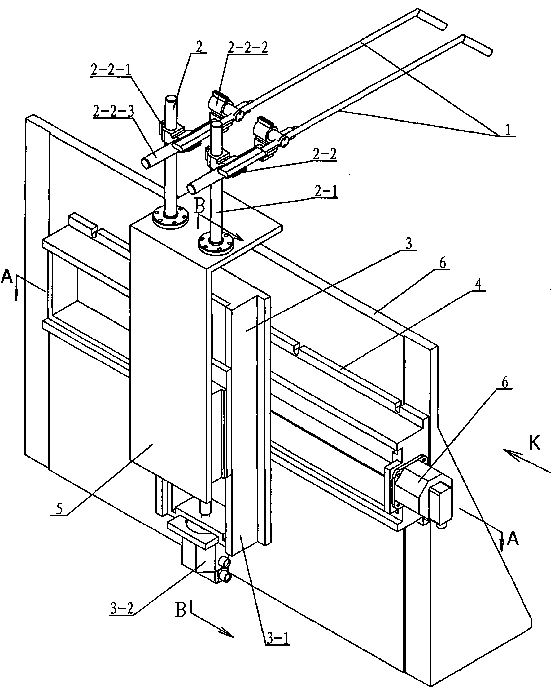
图1是本发明装置的立体结构示意图,图2是图1的K向视图,图3是图1的A-A剖视图,图4是图1的B-B剖视图。Fig. 1 is a three-dimensional structure schematic diagram of the device of the present invention, Fig. 2 is a K-direction view of Fig. 1 , Fig. 3 is a sectional view of A-A of Fig. 1 , and Fig. 4 is a sectional view of B-B of Fig. 1 .
具体实施方式Detailed ways
具体实施方式一:结合图1~图4说明本实施方式,本实施方式包括竖向滑动机构3、纵向滑动机构4、调整架5、固定座6、两个烧炬1和两个调整机构2,纵向滑动机构4由壳体4-1、纵向伺服电机4-2、纵向联轴器4-3、纵向滚珠丝杠4-4、纵向丝母4-5、前支撑轴承4-6、前轴承座4-7、后支撑轴承4-8和后轴承座4-9组成,前轴承座4-7和后轴承座4-9分别固装在壳体4-1内的前端和后端,前支撑轴承4-6安装在前轴承座4-7中,后支撑轴承4-8安装在后轴承座4-9中,纵向滚珠丝杠4-4的两端分别设置在前支撑轴承4-6和后支撑轴承4-8的内孔中,纵向丝母4-5与纵向滚珠丝杠4-4螺纹连接,纵向滚珠丝杠4-4的输入端通过纵向联轴器4-3与纵向伺服电机4-2的输出端连接,纵向伺服电机4-2固装在壳体4-1上,竖向滑动机构3由滑架3-1、竖向伺服电机3-2、竖向联轴器3-3、竖向滚珠丝杠3-4、竖向丝母3-5、上支撑轴承3-6、上轴承座3-7、下支撑轴承3-8和下轴承座3-9组成,上轴承座3-7和下轴承座3-9分别固装在滑架3-1内的上端和下端,上支撑轴承3-6安装在上轴承座3-7中,下支撑轴承3-8安装在下轴承座3-9中,竖向滚珠丝杠3-4的两端分别设置在上支撑轴承3-6和下支撑轴承3-8的内孔中,竖向丝母3-5与竖向滚珠丝杠3-4螺纹连接,竖向滚珠丝杠3-4的输入端通过竖向联轴器3-3与竖向伺服电机3-2的输出端连接,竖向伺服电机3-2固装在滑架3-1上,纵向滑动机构4上的壳体4-1通过连接元件与固定座6连接,竖向滑动机构3上的滑架3-1通过连接元件与纵向滑动机构4上的纵向丝母4-5连接,调整架5由调整平板5-1随动板5-2和连接板5-3组成,调整平板5-1垂直设置在随动板5-2的一端,且二者制成一体,连接板5-3与随动板5-2固接,且连接板5-3位于调整平板5-1一侧,连接板5-3通过连接元件与竖向丝母3-5连接,每个调整机构2由支撑柱2-1和调整架2-2组成,调整架2-2固装在支撑柱2-1上,两个调整机构2沿固定座6的纵向设置,且调整机构2上的支撑柱2-1固装在调整平板5-1上,每个调整架2-2上装配有一个烧炬1。使用时,固定座6安装在旋压机旋轮座上;纵向滑动机构4采用纵向伺服电机4-2、纵向滚珠丝杠4-4和纵向丝母4-5传动结构,竖向滑动机构3采用竖向伺服电机3-2、竖向滚珠丝杠3-4和竖向丝母3-5传动结构,可以精确的控制纵向滑动和竖向滑动位置,并可以使烧炬1按照任意轨迹进行。纵向伺服电机4-2和竖向伺服电机3-2分别通过导线与旋压机数控系统相连;两个烧炬1分别通过导线与数控系统相连,可以进行圆弧、样条等任意曲线,以配合加热部分工艺需要,并可以在加热过程中通过调整竖向滑动机构3和纵向滑动机构4的位置来调整加热火焰的位置,从而调整加热的温度。竖向滑动机构3的上下运动可实现对烧炬1与工件之间距离的精确控制,从而精确控制工件的实际温度,提高了零件的一致性。降低了工人的劳动强度。Specific Embodiment 1: This embodiment is described with reference to Figures 1 to 4. This embodiment includes a vertical sliding mechanism 3, a longitudinal sliding mechanism 4, an
加热过程有两个加热程序:(1)、预热程序:在旋压加工开始之前编程控制纵向滑动机构4、竖向滑动机构3和加热工件上需加工的区域;(2)、加工程序:在旋压加工过程中,通过对纵向滑动机构4和竖向滑动机构3数控控制,实现火焰加热轨迹针对工件实际轮廓的跟随加热,保证工件温度场的均匀稳定。There are two heating procedures in the heating process: (1), preheating procedure: program control the longitudinal sliding mechanism 4, vertical sliding mechanism 3 and the area to be processed on the heating workpiece before the spinning process starts; (2), processing procedure: During the spinning process, through the numerical control of the longitudinal sliding mechanism 4 and the vertical sliding mechanism 3, the flame heating track can follow the actual contour of the workpiece to ensure the uniform and stable temperature field of the workpiece.
具体实施方式二:结合图1和图2说明本实施方式,本实施方式的每个调整架2-2由第一万向节2-2-1、第二万向节2-2-2和连接杆2-2-3组成,连接杆2-2-3的一端与第一万向节2-2-1连接,连接杆2-2-3的另一端与第二万向节2-2-2连接。这样设计可以使烧炬1在任意方向进行调整。其它组成及连接关系与具体实施方式一相同。Specific embodiment two: This embodiment is described in conjunction with Fig. 1 and Fig. 2, and each adjustment frame 2-2 of this embodiment is composed of the first universal joint 2-2-1, the second universal joint 2-2-2 and The connecting rod 2-2-3 is composed of one end of the connecting rod 2-2-3 connected with the first universal joint 2-2-1, and the other end of the connecting rod 2-2-3 connected with the second universal joint 2-2 -2 connections. This design can make the torch 1 be adjusted in any direction. Other components and connections are the same as those in the first embodiment.
本发明的工作原理:当纵向伺服电机4-2转动时,带动纵向滚珠丝杠4-4转动,通过纵向丝母4-5带动竖向滑动机构3沿着纵向滚珠丝杠4-4的轴线方向运动,从而将旋转运动转化为纵向直线运动;当竖向伺服电机3-2转动时,带动竖向滚珠丝杠3-4转动,通过竖向丝母3-5带动连接板5-3沿着竖向滚珠丝杠3-4的轴线方向运动,从而将旋转运动转化为竖向直线运动;竖向滑动机构3和纵向滑动机构4一起带动调整机构2实现纵向和横向的联动。通过数控系统控制烧炬1的火焰加热范围及高度。Working principle of the present invention: when the longitudinal servo motor 4-2 rotates, it drives the longitudinal ball screw 4-4 to rotate, and the vertical sliding mechanism 3 is driven along the axis of the longitudinal ball screw 4-4 through the longitudinal nut 4-5 Direction movement, so as to convert the rotary motion into longitudinal linear motion; when the vertical servo motor 3-2 rotates, it drives the vertical ball screw 3-4 to rotate, and the vertical screw nut 3-5 drives the connecting plate 5-3 along the The vertical ball screw 3-4 moves in the axial direction, thereby converting the rotational motion into a vertical linear motion; the vertical sliding mechanism 3 and the longitudinal sliding mechanism 4 together drive the adjustment mechanism 2 to realize vertical and horizontal linkage. The flame heating range and height of the torch 1 are controlled by a numerical control system.
Claims (2)
Priority Applications (1)
| Application Number | Priority Date | Filing Date | Title |
|---|---|---|---|
| CN2010105096591A CN101972808B (en) | 2010-10-18 | 2010-10-18 | Independent digital flame following and heating device of hot spinning machine |
Applications Claiming Priority (1)
| Application Number | Priority Date | Filing Date | Title |
|---|---|---|---|
| CN2010105096591A CN101972808B (en) | 2010-10-18 | 2010-10-18 | Independent digital flame following and heating device of hot spinning machine |
Publications (2)
| Publication Number | Publication Date |
|---|---|
| CN101972808A true CN101972808A (en) | 2011-02-16 |
| CN101972808B CN101972808B (en) | 2012-02-22 |
Family
ID=43572731
Family Applications (1)
| Application Number | Title | Priority Date | Filing Date |
|---|---|---|---|
| CN2010105096591A Expired - Fee Related CN101972808B (en) | 2010-10-18 | 2010-10-18 | Independent digital flame following and heating device of hot spinning machine |
Country Status (1)
| Country | Link |
|---|---|
| CN (1) | CN101972808B (en) |
Cited By (18)
| Publication number | Priority date | Publication date | Assignee | Title |
|---|---|---|---|---|
| CN103272948A (en) * | 2013-05-06 | 2013-09-04 | 上海交通大学 | Spinning heating device |
| CN104525764A (en) * | 2014-12-30 | 2015-04-22 | 沈阳欧施盾新材料科技有限公司 | Automatic firing system for spinning hot necking machine |
| CN104624765A (en) * | 2014-12-03 | 2015-05-20 | 哈尔滨工业大学 | Rotary heating and temperature control device in combined spinning process of dissimilar metal |
| CN105478544A (en) * | 2015-12-24 | 2016-04-13 | 中铁宝桥集团有限公司 | Curved F-type steel rail hot-bending molding device and curved F-type steel rail hot-bending molding device method |
| CN106029247A (en) * | 2014-04-10 | 2016-10-12 | 川崎重工业株式会社 | Spinning forming device |
| CN106238518A (en) * | 2016-09-29 | 2016-12-21 | 华中科技大学 | A kind of multipurpose sensing Heating Experiment platform and using method thereof |
| CN107413893A (en) * | 2017-04-29 | 2017-12-01 | 镇江倍斯特曼新材料研究有限公司 | A kind of leveling apparatus of sheet metal |
| CN109500188A (en) * | 2018-12-26 | 2019-03-22 | 金堆城钼业股份有限公司 | A kind of molybdenum crucible two-wheel mistake is away from hot shear spinning forming device and method |
| CN110508658A (en) * | 2019-07-31 | 2019-11-29 | 上海航天精密机械研究所 | Steel pipe spinning temperature automatic control equipment and control method |
| CN111026050A (en) * | 2019-11-22 | 2020-04-17 | 北京航空航天大学 | Hot spinning processing intelligent control system based on Beifu industrial Ethernet |
| CN111922167A (en) * | 2020-08-19 | 2020-11-13 | 西安航天发动机有限公司 | Hot spinning forming method for variable-wall-thickness extension section of low-density niobium alloy |
| CN112404272A (en) * | 2020-11-10 | 2021-02-26 | 中南大学 | A kind of follow-up heating spinning device and spinning method of head piece |
| CN113333623A (en) * | 2021-05-26 | 2021-09-03 | 河北岳丰管件产业技术研究有限公司 | Spinning type end socket and end socket spinning equipment thereof |
| CN116274582A (en) * | 2022-12-29 | 2023-06-23 | 海鹰空天材料研究院(苏州)有限责任公司 | Spinning Preheating Mechanism and Spinning Forming Device for Super-Long Cylindrical Parts |
| CN116372003A (en) * | 2022-12-29 | 2023-07-04 | 海鹰空天材料研究院(苏州)有限责任公司 | A spinning forming device for super-long cylindrical parts |
| CN117019897A (en) * | 2023-08-16 | 2023-11-10 | 斯宾仪(上海)设备制造有限公司 | Flame heater for aluminum pipe hot rolling |
| CN119910073A (en) * | 2025-03-31 | 2025-05-02 | 台州市特创汽配科技有限公司 | A hot spinning processing device for air reducer piston |
| CN120133363A (en) * | 2025-03-25 | 2025-06-13 | 北京卫星制造厂有限公司 | A hot spinning forming manufacturing method for long-length titanium alloy cylindrical parts |
Citations (4)
| Publication number | Priority date | Publication date | Assignee | Title |
|---|---|---|---|---|
| GB462059A (en) * | 1935-10-14 | 1937-03-02 | Martin Pitt | Improvements in and relating to blow-pipe machines for cutting metal |
| EP0081700A1 (en) * | 1981-11-20 | 1983-06-22 | Air Products And Chemicals, Inc. | Spin forming |
| JPH07185681A (en) * | 1991-04-19 | 1995-07-25 | Compression Technol Inc | Equipment and method for producing both-end closed container |
| CN101391372A (en) * | 2008-10-22 | 2009-03-25 | 中材科技(苏州)有限公司 | Gas cylinder dished head shaping technique |
-
2010
- 2010-10-18 CN CN2010105096591A patent/CN101972808B/en not_active Expired - Fee Related
Patent Citations (4)
| Publication number | Priority date | Publication date | Assignee | Title |
|---|---|---|---|---|
| GB462059A (en) * | 1935-10-14 | 1937-03-02 | Martin Pitt | Improvements in and relating to blow-pipe machines for cutting metal |
| EP0081700A1 (en) * | 1981-11-20 | 1983-06-22 | Air Products And Chemicals, Inc. | Spin forming |
| JPH07185681A (en) * | 1991-04-19 | 1995-07-25 | Compression Technol Inc | Equipment and method for producing both-end closed container |
| CN101391372A (en) * | 2008-10-22 | 2009-03-25 | 中材科技(苏州)有限公司 | Gas cylinder dished head shaping technique |
Cited By (23)
| Publication number | Priority date | Publication date | Assignee | Title |
|---|---|---|---|---|
| CN103272948A (en) * | 2013-05-06 | 2013-09-04 | 上海交通大学 | Spinning heating device |
| CN103272948B (en) * | 2013-05-06 | 2015-04-01 | 上海交通大学 | Spinning heating device |
| CN106029247A (en) * | 2014-04-10 | 2016-10-12 | 川崎重工业株式会社 | Spinning forming device |
| CN104624765A (en) * | 2014-12-03 | 2015-05-20 | 哈尔滨工业大学 | Rotary heating and temperature control device in combined spinning process of dissimilar metal |
| CN104624765B (en) * | 2014-12-03 | 2016-08-24 | 哈尔滨工业大学 | The rotary heating of a kind of dissimilar metal composite spinning process and temperature regulating device |
| CN104525764A (en) * | 2014-12-30 | 2015-04-22 | 沈阳欧施盾新材料科技有限公司 | Automatic firing system for spinning hot necking machine |
| CN104525764B (en) * | 2014-12-30 | 2016-04-20 | 沈阳欧施盾新材料科技有限公司 | A kind of automatic baking ignition system for spinning heating charge machine |
| CN105478544A (en) * | 2015-12-24 | 2016-04-13 | 中铁宝桥集团有限公司 | Curved F-type steel rail hot-bending molding device and curved F-type steel rail hot-bending molding device method |
| CN106238518A (en) * | 2016-09-29 | 2016-12-21 | 华中科技大学 | A kind of multipurpose sensing Heating Experiment platform and using method thereof |
| CN107413893B (en) * | 2017-04-29 | 2018-11-16 | 扬州市三诚机械制造有限公司 | A kind of leveling apparatus of sheet metal |
| CN107413893A (en) * | 2017-04-29 | 2017-12-01 | 镇江倍斯特曼新材料研究有限公司 | A kind of leveling apparatus of sheet metal |
| CN109500188A (en) * | 2018-12-26 | 2019-03-22 | 金堆城钼业股份有限公司 | A kind of molybdenum crucible two-wheel mistake is away from hot shear spinning forming device and method |
| CN110508658A (en) * | 2019-07-31 | 2019-11-29 | 上海航天精密机械研究所 | Steel pipe spinning temperature automatic control equipment and control method |
| CN111026050A (en) * | 2019-11-22 | 2020-04-17 | 北京航空航天大学 | Hot spinning processing intelligent control system based on Beifu industrial Ethernet |
| CN111922167A (en) * | 2020-08-19 | 2020-11-13 | 西安航天发动机有限公司 | Hot spinning forming method for variable-wall-thickness extension section of low-density niobium alloy |
| CN112404272A (en) * | 2020-11-10 | 2021-02-26 | 中南大学 | A kind of follow-up heating spinning device and spinning method of head piece |
| CN113333623A (en) * | 2021-05-26 | 2021-09-03 | 河北岳丰管件产业技术研究有限公司 | Spinning type end socket and end socket spinning equipment thereof |
| CN113333623B (en) * | 2021-05-26 | 2022-09-06 | 河北岳丰管件产业技术研究有限公司 | Spinning type end socket and end socket spinning equipment thereof |
| CN116274582A (en) * | 2022-12-29 | 2023-06-23 | 海鹰空天材料研究院(苏州)有限责任公司 | Spinning Preheating Mechanism and Spinning Forming Device for Super-Long Cylindrical Parts |
| CN116372003A (en) * | 2022-12-29 | 2023-07-04 | 海鹰空天材料研究院(苏州)有限责任公司 | A spinning forming device for super-long cylindrical parts |
| CN117019897A (en) * | 2023-08-16 | 2023-11-10 | 斯宾仪(上海)设备制造有限公司 | Flame heater for aluminum pipe hot rolling |
| CN120133363A (en) * | 2025-03-25 | 2025-06-13 | 北京卫星制造厂有限公司 | A hot spinning forming manufacturing method for long-length titanium alloy cylindrical parts |
| CN119910073A (en) * | 2025-03-31 | 2025-05-02 | 台州市特创汽配科技有限公司 | A hot spinning processing device for air reducer piston |
Also Published As
| Publication number | Publication date |
|---|---|
| CN101972808B (en) | 2012-02-22 |
Similar Documents
| Publication | Publication Date | Title |
|---|---|---|
| CN101972808B (en) | Independent digital flame following and heating device of hot spinning machine | |
| CN106493463B (en) | A kind of machining equipment being able to achieve any angle cutting | |
| CN105082530B (en) | A kind of sweating welder of corrugated pipe connector | |
| US3988913A (en) | Isothermal metal forming apparatus | |
| CN201350542Y (en) | Automatic welding machine special for hydrocylinder girth welding | |
| Najafabady et al. | An experimental study on dimensional accuracy, surface quality, and hardness of Ti-6Al-4 V titanium alloy sheet in hot incremental forming | |
| CN108673051B (en) | Numerical control rolling machine tool for rolling outer circle of torsion shaft | |
| CN104117547B (en) | A kind of Warm Extrusion gear stick continuous extrusion die and processing method thereof | |
| CN202377448U (en) | Multifunctional horizontal ring rolling machine | |
| CN102527890A (en) | Multifunctional horizontal ring rolling machine | |
| CA2935846A1 (en) | System for superplastic forming of a component from a blank | |
| CN103341690B (en) | Numerical-control adjustable hard alloy double-light-beam welding device and welding method thereof | |
| CN106738062A (en) | The die cutter roller and its blade forming method of a kind of two-dimensional gradient | |
| CN111151696A (en) | Forging method of frustum-shaped flange forging | |
| US20200114409A1 (en) | Friction forming | |
| CN101185952A (en) | Two-sided roll milling forming method and two-sided roll milling forming equipment | |
| CN105013939B (en) | Stirring friction forming device and technology based on self heating | |
| CN116351942A (en) | A multi-pass heating spinning method for high-strength titanium alloy sheet | |
| CN201172095Y (en) | Double ended rolling forming device | |
| CN205732288U (en) | A kind of point of three-roller Y shaped milling train of transmission direct-drive type | |
| CN102152070A (en) | Method for manufacturing ring-shaped piece | |
| CN112548360A (en) | Pipe laser cutting machine | |
| CN208005150U (en) | More metal arc formula band milling cutter 3D printing devices | |
| CN206966853U (en) | A kind of efficient cutting processing equipment | |
| CN111872289B (en) | A large multi-station radial and axial automatic ring rolling machine |
Legal Events
| Date | Code | Title | Description |
|---|---|---|---|
| C06 | Publication | ||
| PB01 | Publication | ||
| C10 | Entry into substantive examination | ||
| SE01 | Entry into force of request for substantive examination | ||
| C14 | Grant of patent or utility model | ||
| GR01 | Patent grant | ||
| CF01 | Termination of patent right due to non-payment of annual fee |
Granted publication date: 20120222 Termination date: 20211018 |
|
| CF01 | Termination of patent right due to non-payment of annual fee |