CN101938493B - Generating and implementing a signal protocol and interface for higher data rates - Google Patents
Generating and implementing a signal protocol and interface for higher data rates Download PDFInfo
- Publication number
- CN101938493B CN101938493B CN2010102874789A CN201010287478A CN101938493B CN 101938493 B CN101938493 B CN 101938493B CN 2010102874789 A CN2010102874789 A CN 2010102874789A CN 201010287478 A CN201010287478 A CN 201010287478A CN 101938493 B CN101938493 B CN 101938493B
- Authority
- CN
- China
- Prior art keywords
- data
- package
- main frame
- mddi
- link
- Prior art date
- Legal status (The legal status is an assumption and is not a legal conclusion. Google has not performed a legal analysis and makes no representation as to the accuracy of the status listed.)
- Expired - Fee Related
Links
- 238000004891 communication Methods 0.000 claims abstract description 107
- 230000005540 biological transmission Effects 0.000 claims description 90
- 238000000034 method Methods 0.000 claims description 86
- 230000004087 circulation Effects 0.000 claims description 60
- 230000015572 biosynthetic process Effects 0.000 claims description 6
- 230000002045 lasting effect Effects 0.000 claims description 4
- 238000012546 transfer Methods 0.000 abstract description 58
- 230000007246 mechanism Effects 0.000 abstract description 22
- 230000002441 reversible effect Effects 0.000 description 210
- 230000008569 process Effects 0.000 description 52
- 238000012545 processing Methods 0.000 description 38
- 238000005538 encapsulation Methods 0.000 description 29
- 230000001360 synchronised effect Effects 0.000 description 27
- 238000005516 engineering process Methods 0.000 description 26
- 238000005259 measurement Methods 0.000 description 25
- 230000008859 change Effects 0.000 description 23
- 238000005070 sampling Methods 0.000 description 22
- 239000000945 filler Substances 0.000 description 20
- 230000006870 function Effects 0.000 description 20
- 239000004020 conductor Substances 0.000 description 19
- 238000012795 verification Methods 0.000 description 19
- 238000006243 chemical reaction Methods 0.000 description 18
- 230000000630 rising effect Effects 0.000 description 17
- 238000011282 treatment Methods 0.000 description 15
- 230000033228 biological regulation Effects 0.000 description 14
- 230000005059 dormancy Effects 0.000 description 13
- 238000012937 correction Methods 0.000 description 12
- 230000007958 sleep Effects 0.000 description 12
- 230000000284 resting effect Effects 0.000 description 11
- 230000008901 benefit Effects 0.000 description 10
- 230000004044 response Effects 0.000 description 10
- 230000000295 complement effect Effects 0.000 description 8
- 230000000694 effects Effects 0.000 description 8
- 230000033001 locomotion Effects 0.000 description 8
- 230000002633 protecting effect Effects 0.000 description 8
- 230000011664 signaling Effects 0.000 description 8
- GOLXNESZZPUPJE-UHFFFAOYSA-N spiromesifen Chemical compound CC1=CC(C)=CC(C)=C1C(C(O1)=O)=C(OC(=O)CC(C)(C)C)C11CCCC1 GOLXNESZZPUPJE-UHFFFAOYSA-N 0.000 description 8
- 230000009471 action Effects 0.000 description 7
- 238000007906 compression Methods 0.000 description 7
- 230000006835 compression Effects 0.000 description 7
- 125000004122 cyclic group Chemical group 0.000 description 7
- 238000010586 diagram Methods 0.000 description 7
- 230000003068 static effect Effects 0.000 description 7
- 241001269238 Data Species 0.000 description 6
- 238000013461 design Methods 0.000 description 6
- 230000001965 increasing effect Effects 0.000 description 6
- 230000002349 favourable effect Effects 0.000 description 5
- 230000002452 interceptive effect Effects 0.000 description 5
- 238000010276 construction Methods 0.000 description 4
- 230000001276 controlling effect Effects 0.000 description 4
- 230000003111 delayed effect Effects 0.000 description 4
- 239000011521 glass Substances 0.000 description 4
- 238000002360 preparation method Methods 0.000 description 4
- 238000011084 recovery Methods 0.000 description 4
- 230000002829 reductive effect Effects 0.000 description 4
- 238000003860 storage Methods 0.000 description 4
- 238000013459 approach Methods 0.000 description 3
- 230000002457 bidirectional effect Effects 0.000 description 3
- 230000003139 buffering effect Effects 0.000 description 3
- 238000004364 calculation method Methods 0.000 description 3
- 238000001514 detection method Methods 0.000 description 3
- 238000009432 framing Methods 0.000 description 3
- 238000011221 initial treatment Methods 0.000 description 3
- 238000007689 inspection Methods 0.000 description 3
- 230000014759 maintenance of location Effects 0.000 description 3
- 238000010295 mobile communication Methods 0.000 description 3
- 238000006467 substitution reaction Methods 0.000 description 3
- 230000000007 visual effect Effects 0.000 description 3
- 230000002618 waking effect Effects 0.000 description 3
- ZLHLYESIHSHXGM-UHFFFAOYSA-N 4,6-dimethyl-1h-imidazo[1,2-a]purin-9-one Chemical compound N=1C(C)=CN(C2=O)C=1N(C)C1=C2NC=N1 ZLHLYESIHSHXGM-UHFFFAOYSA-N 0.000 description 2
- 238000002266 amputation Methods 0.000 description 2
- 230000000712 assembly Effects 0.000 description 2
- 238000000429 assembly Methods 0.000 description 2
- 239000003990 capacitor Substances 0.000 description 2
- 230000007423 decrease Effects 0.000 description 2
- 230000002950 deficient Effects 0.000 description 2
- 230000001934 delay Effects 0.000 description 2
- 230000001976 improved effect Effects 0.000 description 2
- 230000000977 initiatory effect Effects 0.000 description 2
- 238000004519 manufacturing process Methods 0.000 description 2
- 239000000463 material Substances 0.000 description 2
- 238000012986 modification Methods 0.000 description 2
- 230000004048 modification Effects 0.000 description 2
- 238000012544 monitoring process Methods 0.000 description 2
- 230000003287 optical effect Effects 0.000 description 2
- 230000000644 propagated effect Effects 0.000 description 2
- 238000009877 rendering Methods 0.000 description 2
- 230000008093 supporting effect Effects 0.000 description 2
- 230000009897 systematic effect Effects 0.000 description 2
- 238000012731 temporal analysis Methods 0.000 description 2
- 238000000700 time series analysis Methods 0.000 description 2
- 230000009466 transformation Effects 0.000 description 2
- HBBGRARXTFLTSG-UHFFFAOYSA-N Lithium ion Chemical compound [Li+] HBBGRARXTFLTSG-UHFFFAOYSA-N 0.000 description 1
- 208000032369 Primary transmission Diseases 0.000 description 1
- 230000001133 acceleration Effects 0.000 description 1
- 230000002411 adverse Effects 0.000 description 1
- 230000003321 amplification Effects 0.000 description 1
- 238000004458 analytical method Methods 0.000 description 1
- 230000004888 barrier function Effects 0.000 description 1
- 230000000739 chaotic effect Effects 0.000 description 1
- 239000011248 coating agent Substances 0.000 description 1
- 238000000576 coating method Methods 0.000 description 1
- 239000003086 colorant Substances 0.000 description 1
- 238000004883 computer application Methods 0.000 description 1
- 239000012141 concentrate Substances 0.000 description 1
- 230000001143 conditioned effect Effects 0.000 description 1
- 238000012790 confirmation Methods 0.000 description 1
- 238000007796 conventional method Methods 0.000 description 1
- 230000008878 coupling Effects 0.000 description 1
- 238000010168 coupling process Methods 0.000 description 1
- 238000005859 coupling reaction Methods 0.000 description 1
- 238000013144 data compression Methods 0.000 description 1
- 230000007547 defect Effects 0.000 description 1
- 230000007812 deficiency Effects 0.000 description 1
- 238000011161 development Methods 0.000 description 1
- 238000009826 distribution Methods 0.000 description 1
- 230000002708 enhancing effect Effects 0.000 description 1
- 210000000887 face Anatomy 0.000 description 1
- 210000003746 feather Anatomy 0.000 description 1
- 239000011888 foil Substances 0.000 description 1
- 210000003128 head Anatomy 0.000 description 1
- 238000003384 imaging method Methods 0.000 description 1
- 230000006698 induction Effects 0.000 description 1
- 238000009434 installation Methods 0.000 description 1
- 230000003993 interaction Effects 0.000 description 1
- 238000011835 investigation Methods 0.000 description 1
- 210000003127 knee Anatomy 0.000 description 1
- 229910001416 lithium ion Inorganic materials 0.000 description 1
- 230000007774 longterm Effects 0.000 description 1
- 238000012423 maintenance Methods 0.000 description 1
- 238000007726 management method Methods 0.000 description 1
- 238000013507 mapping Methods 0.000 description 1
- 230000005055 memory storage Effects 0.000 description 1
- 238000003199 nucleic acid amplification method Methods 0.000 description 1
- 239000013307 optical fiber Substances 0.000 description 1
- 238000005457 optimization Methods 0.000 description 1
- 238000012856 packing Methods 0.000 description 1
- 230000037361 pathway Effects 0.000 description 1
- 230000000737 periodic effect Effects 0.000 description 1
- 230000002093 peripheral effect Effects 0.000 description 1
- 230000000750 progressive effect Effects 0.000 description 1
- 230000001915 proofreading effect Effects 0.000 description 1
- 230000001105 regulatory effect Effects 0.000 description 1
- 229920006395 saturated elastomer Polymers 0.000 description 1
- 230000008054 signal transmission Effects 0.000 description 1
- 230000005236 sound signal Effects 0.000 description 1
- 230000006641 stabilisation Effects 0.000 description 1
- 230000002123 temporal effect Effects 0.000 description 1
- 238000012360 testing method Methods 0.000 description 1
- 230000007723 transport mechanism Effects 0.000 description 1
Images


Classifications
-
- G—PHYSICS
- G06—COMPUTING; CALCULATING OR COUNTING
- G06F—ELECTRIC DIGITAL DATA PROCESSING
- G06F3/00—Input arrangements for transferring data to be processed into a form capable of being handled by the computer; Output arrangements for transferring data from processing unit to output unit, e.g. interface arrangements
- G06F3/14—Digital output to display device ; Cooperation and interconnection of the display device with other functional units
-
- H—ELECTRICITY
- H04—ELECTRIC COMMUNICATION TECHNIQUE
- H04L—TRANSMISSION OF DIGITAL INFORMATION, e.g. TELEGRAPHIC COMMUNICATION
- H04L1/00—Arrangements for detecting or preventing errors in the information received
- H04L1/004—Arrangements for detecting or preventing errors in the information received by using forward error control
- H04L1/0056—Systems characterized by the type of code used
- H04L1/0061—Error detection codes
-
- H—ELECTRICITY
- H04—ELECTRIC COMMUNICATION TECHNIQUE
- H04L—TRANSMISSION OF DIGITAL INFORMATION, e.g. TELEGRAPHIC COMMUNICATION
- H04L65/00—Network arrangements, protocols or services for supporting real-time applications in data packet communication
- H04L65/60—Network streaming of media packets
- H04L65/70—Media network packetisation
-
- H—ELECTRICITY
- H04—ELECTRIC COMMUNICATION TECHNIQUE
- H04L—TRANSMISSION OF DIGITAL INFORMATION, e.g. TELEGRAPHIC COMMUNICATION
- H04L1/00—Arrangements for detecting or preventing errors in the information received
- H04L1/24—Testing correct operation
- H04L1/245—Testing correct operation by using the properties of transmission codes
-
- H—ELECTRICITY
- H04—ELECTRIC COMMUNICATION TECHNIQUE
- H04L—TRANSMISSION OF DIGITAL INFORMATION, e.g. TELEGRAPHIC COMMUNICATION
- H04L12/00—Data switching networks
- H04L12/64—Hybrid switching systems
-
- H—ELECTRICITY
- H04—ELECTRIC COMMUNICATION TECHNIQUE
- H04L—TRANSMISSION OF DIGITAL INFORMATION, e.g. TELEGRAPHIC COMMUNICATION
- H04L65/00—Network arrangements, protocols or services for supporting real-time applications in data packet communication
- H04L65/1066—Session management
- H04L65/1101—Session protocols
-
- H—ELECTRICITY
- H04—ELECTRIC COMMUNICATION TECHNIQUE
- H04L—TRANSMISSION OF DIGITAL INFORMATION, e.g. TELEGRAPHIC COMMUNICATION
- H04L69/00—Network arrangements, protocols or services independent of the application payload and not provided for in the other groups of this subclass
- H04L69/03—Protocol definition or specification
-
- H—ELECTRICITY
- H04—ELECTRIC COMMUNICATION TECHNIQUE
- H04L—TRANSMISSION OF DIGITAL INFORMATION, e.g. TELEGRAPHIC COMMUNICATION
- H04L69/00—Network arrangements, protocols or services independent of the application payload and not provided for in the other groups of this subclass
- H04L69/18—Multiprotocol handlers, e.g. single devices capable of handling multiple protocols
-
- H—ELECTRICITY
- H04—ELECTRIC COMMUNICATION TECHNIQUE
- H04L—TRANSMISSION OF DIGITAL INFORMATION, e.g. TELEGRAPHIC COMMUNICATION
- H04L69/00—Network arrangements, protocols or services independent of the application payload and not provided for in the other groups of this subclass
- H04L69/22—Parsing or analysis of headers
-
- H—ELECTRICITY
- H04—ELECTRIC COMMUNICATION TECHNIQUE
- H04L—TRANSMISSION OF DIGITAL INFORMATION, e.g. TELEGRAPHIC COMMUNICATION
- H04L69/00—Network arrangements, protocols or services independent of the application payload and not provided for in the other groups of this subclass
- H04L69/24—Negotiation of communication capabilities
-
- H—ELECTRICITY
- H04—ELECTRIC COMMUNICATION TECHNIQUE
- H04L—TRANSMISSION OF DIGITAL INFORMATION, e.g. TELEGRAPHIC COMMUNICATION
- H04L69/00—Network arrangements, protocols or services independent of the application payload and not provided for in the other groups of this subclass
- H04L69/30—Definitions, standards or architectural aspects of layered protocol stacks
- H04L69/32—Architecture of open systems interconnection [OSI] 7-layer type protocol stacks, e.g. the interfaces between the data link level and the physical level
- H04L69/322—Intralayer communication protocols among peer entities or protocol data unit [PDU] definitions
- H04L69/324—Intralayer communication protocols among peer entities or protocol data unit [PDU] definitions in the data link layer [OSI layer 2], e.g. HDLC
-
- H—ELECTRICITY
- H04—ELECTRIC COMMUNICATION TECHNIQUE
- H04L—TRANSMISSION OF DIGITAL INFORMATION, e.g. TELEGRAPHIC COMMUNICATION
- H04L7/00—Arrangements for synchronising receiver with transmitter
- H04L7/04—Speed or phase control by synchronisation signals
- H04L7/10—Arrangements for initial synchronisation
-
- H—ELECTRICITY
- H04—ELECTRIC COMMUNICATION TECHNIQUE
- H04L—TRANSMISSION OF DIGITAL INFORMATION, e.g. TELEGRAPHIC COMMUNICATION
- H04L9/00—Cryptographic mechanisms or cryptographic arrangements for secret or secure communications; Network security protocols
- H04L9/40—Network security protocols
-
- H—ELECTRICITY
- H04—ELECTRIC COMMUNICATION TECHNIQUE
- H04N—PICTORIAL COMMUNICATION, e.g. TELEVISION
- H04N21/00—Selective content distribution, e.g. interactive television or video on demand [VOD]
- H04N21/40—Client devices specifically adapted for the reception of or interaction with content, e.g. set-top-box [STB]; Operations thereof
- H04N21/41—Structure of client; Structure of client peripherals
- H04N21/4104—Peripherals receiving signals from specially adapted client devices
- H04N21/4122—Peripherals receiving signals from specially adapted client devices additional display device, e.g. video projector
-
- H—ELECTRICITY
- H04—ELECTRIC COMMUNICATION TECHNIQUE
- H04N—PICTORIAL COMMUNICATION, e.g. TELEVISION
- H04N21/00—Selective content distribution, e.g. interactive television or video on demand [VOD]
- H04N21/40—Client devices specifically adapted for the reception of or interaction with content, e.g. set-top-box [STB]; Operations thereof
- H04N21/41—Structure of client; Structure of client peripherals
- H04N21/414—Specialised client platforms, e.g. receiver in car or embedded in a mobile appliance
- H04N21/41407—Specialised client platforms, e.g. receiver in car or embedded in a mobile appliance embedded in a portable device, e.g. video client on a mobile phone, PDA, laptop
-
- H—ELECTRICITY
- H04—ELECTRIC COMMUNICATION TECHNIQUE
- H04N—PICTORIAL COMMUNICATION, e.g. TELEVISION
- H04N21/00—Selective content distribution, e.g. interactive television or video on demand [VOD]
- H04N21/40—Client devices specifically adapted for the reception of or interaction with content, e.g. set-top-box [STB]; Operations thereof
- H04N21/43—Processing of content or additional data, e.g. demultiplexing additional data from a digital video stream; Elementary client operations, e.g. monitoring of home network or synchronising decoder's clock; Client middleware
- H04N21/436—Interfacing a local distribution network, e.g. communicating with another STB or one or more peripheral devices inside the home
- H04N21/4363—Adapting the video or multiplex stream to a specific local network, e.g. a IEEE 1394 or Bluetooth® network
- H04N21/43632—Adapting the video or multiplex stream to a specific local network, e.g. a IEEE 1394 or Bluetooth® network involving a wired protocol, e.g. IEEE 1394
-
- H—ELECTRICITY
- H04—ELECTRIC COMMUNICATION TECHNIQUE
- H04L—TRANSMISSION OF DIGITAL INFORMATION, e.g. TELEGRAPHIC COMMUNICATION
- H04L7/00—Arrangements for synchronising receiver with transmitter
- H04L7/0008—Synchronisation information channels, e.g. clock distribution lines
-
- H—ELECTRICITY
- H04—ELECTRIC COMMUNICATION TECHNIQUE
- H04L—TRANSMISSION OF DIGITAL INFORMATION, e.g. TELEGRAPHIC COMMUNICATION
- H04L7/00—Arrangements for synchronising receiver with transmitter
- H04L7/04—Speed or phase control by synchronisation signals
- H04L7/048—Speed or phase control by synchronisation signals using the properties of error detecting or error correcting codes, e.g. parity as synchronisation signal
-
- H—ELECTRICITY
- H04—ELECTRIC COMMUNICATION TECHNIQUE
- H04M—TELEPHONIC COMMUNICATION
- H04M1/00—Substation equipment, e.g. for use by subscribers
- H04M1/72—Mobile telephones; Cordless telephones, i.e. devices for establishing wireless links to base stations without route selection
- H04M1/724—User interfaces specially adapted for cordless or mobile telephones
- H04M1/72403—User interfaces specially adapted for cordless or mobile telephones with means for local support of applications that increase the functionality
- H04M1/72409—User interfaces specially adapted for cordless or mobile telephones with means for local support of applications that increase the functionality by interfacing with external accessories
- H04M1/72412—User interfaces specially adapted for cordless or mobile telephones with means for local support of applications that increase the functionality by interfacing with external accessories using two-way short-range wireless interfaces
-
- Y—GENERAL TAGGING OF NEW TECHNOLOGICAL DEVELOPMENTS; GENERAL TAGGING OF CROSS-SECTIONAL TECHNOLOGIES SPANNING OVER SEVERAL SECTIONS OF THE IPC; TECHNICAL SUBJECTS COVERED BY FORMER USPC CROSS-REFERENCE ART COLLECTIONS [XRACs] AND DIGESTS
- Y02—TECHNOLOGIES OR APPLICATIONS FOR MITIGATION OR ADAPTATION AGAINST CLIMATE CHANGE
- Y02D—CLIMATE CHANGE MITIGATION TECHNOLOGIES IN INFORMATION AND COMMUNICATION TECHNOLOGIES [ICT], I.E. INFORMATION AND COMMUNICATION TECHNOLOGIES AIMING AT THE REDUCTION OF THEIR OWN ENERGY USE
- Y02D30/00—Reducing energy consumption in communication networks
- Y02D30/70—Reducing energy consumption in communication networks in wireless communication networks
Abstract
A data Interface for transferring digital data between a host and a client over a communication path using packet structures linked together to form a communication protocol for communicating a pre-selected set of digital control and presentation data. The signal protocol is used by link controllers configured to generate, transmit, and receive packets forming the communications protocol, and to form digital data into one or more types of data packets, with at least one residing in the host device and being coupled to the client through the communications path. The interface provides a cost-effective, low power, bi-directional, high-speed data transfer mechanism over a short-range 'serial' type data link, which lends itself to implementation with miniature connectors and thin flexible cables which are especially useful in connecting display elements such as wearable micro-displays to portable computers and wireless communication devices.
Description
The application is that application number is PCT/US2004/017579, the applying date is on June 2nd, 2004, priority date is on June 2nd, 2003, denomination of invention for the PCT application of " generate and implement be used for more signal protocol and the interface of High Data Rate " enter country's stage after application number be dividing an application of 200480021021.1 Chinese invention patent application.
Present application for patent advocates that the name to application on June 2nd, 2003 is called the provisional application case the 60/475th of " Generating and Implementing aSignal Protocol and Interface for Higher Data Rates ", No. 459 priority, described provisional application case is amortized to this assignee and perspicuously is incorporated herein by reference.
Technical field
The present invention about a kind of for presenting communication between the device or transmit digital signal agreement and the process of signal at host apparatus and client audio/visual with High Data Rate.More particularly, the present invention is sent to miniature display unit or other present the technology of device with the digital signal of multimedia and other type from wireless device about a kind of transfer mechanism for using the low-power High Data Rate.
Background technology
Computer, electronic game Related product and various video technique (for example DVD and high definition VCR) develop rapidly in the past few decades, so that static, video that can resolution is more and more higher, video request program and figure and picture (even when comprising the text of some type) are presented to the end user of this kind equipment.These progressive requirements are again used more high-resolution electronics finder, such as high definition video monitor, HDTV monitor or special image projecting element.With the combination of these vision imagings and high definition or high quality audio data (such as when using CD class sound reproduction, DVD and other also to have the device of related audio signal output) be used for as the end user create one more true to nature, content is abundanter or more real multimedia experiences.In addition, high quality sound system and music transport mechanisms that the height such as the MP3 player moves have been developed, to the end user only there to be presenting of audio frequency.
Present in the environment in exemplary video, usually use prior art to transmit video data can the most relevantly be called slow or general speed (being about per second one to tens kilobit).Follow this data and be buffered or be stored in of short duration or the long-term storage apparatus, play at wanted finder to delay (after a while).For example, can utilize the program that resides on the computer with modulator-demodulator or the Internet jockey to come " leap " or use the Internet to transmit image, to receive or to transmit the existing useful data of an image in digital earth's surface.Similarly transmission can be carried out with wireless device, such as the portable computer of being furnished with radio modem or wireless personal digital assistant (Personal Data Assistant) (PDA) or radio telephone.
In case be received, data are stored in memory component, circuit or device (such as RAM or flash memory) and are comprised in the external memory in this locality, for broadcast.Depend on data volume and image resolution, broadcast may begin ground comparatively fast or have the delay of long period.Meaning namely, in some instances, image presents the real-time broadcast to a certain degree that allows not need to be permitted multidata very little or low resolution image, or allows to use certain type buffer memory, so that after short delay, when transmitting more materials, present some material.In a single day do not interrupt if transmit link, then present process and begin, described transmission is quite transparent to the end user of finder.
Usually know one of technology and compress data for establishment static images or dynamic video with the transmission of expedited data via communication link with some, described technology can such as by JPEG (joint photographic experts group) (Joint Photographic Experts Group) (JPEG), Motion Picture Experts Group (Motion Picture Experts Group) (MPEG) and other the well-known normal structures in media, computer and the communication industry or the technology of company's defined.This sends quantitative information to by the position with lesser amt and allows to transmit quickly image or data.
In case data are sent to " this locality " device such as computer or other receiving system, gained information is with regard to decompressed (or using special decoding player plays), and (if need) is decoded, and is prepared to present resolution and controlling element based on correspondence available and suitably presents.For example, take advantage of according to X the Y pixel screen resolution typical computer video resolution usually from be low to moderate the 480x640 pixel, to 600x800 again in the scope of 1024x1024, although under hope or the condition that needs, generally may use multiple other resolution.
Image presents the impact that also is subject to following factor: presentation content, and given Video Controller reaches employed any extra overhead digit (overhead bit) in the ability of controlling image aspect the colored grade of specific predefine or color depth (for generation of every pixel position of colour) and the tone intensity.For example, but expect typical computer present can with from every pixel about 8 to 32 or the more any color depth the multidigit show various colors (depth and tone), although also can use other value.
According to above value, can find out on the scope from minimum to the highest typical resolution and color depth the arbitrary data volume given screen image will require to transmit from 2.45 megabits (Mb) data to about 33.55Mb data.When watching video or dynamic image with the speed of per second 30 frames, required data volume is about per second 73.7 to 1,006 megabit (Mbps) data, or about per second 9.21 to 125.75 Mbytes (MBps).In addition, may wish to provide in conjunction with image voice data (such as being used for multimedia presentation), or provide voice data to present (such as the music of CD Quality) as independent high definition audio.Also can adopt the extra signal of processing interactive order, control or signal.In these options each all can increase even more data to be transmitted.In a word, when hope sends high-quality or high resolution image data and high quality audio information or data signals to end user when creating a kind of abundant in content experience, will present element and be configured to provide the source of these categorical datas or the high rate of data signalling link between the host apparatus.
The data transfer rate of about per second 115 kilobytes (KBps) or per second 920 kilobits (Kbps) can be processed by the modulator-demodulator serial line interface routinely.Can adapt to speed such as other interface of USB serial line interface and transmit up to the data of 12MBps, and such as use IEEE (Institute of Electrical and Electronics Engineers) (IEEE) the special high speed that disposes of 1394 standards transmit and can about speed of 100 to 400MBps carry out.Unfortunately, these rates are conceived to for the wireless data device in future and the desirable High Data Rate of service less than discussed above, and described wireless data device and service are used for providing high-resolution, abundant in content output signal to drive portable video display or audio devices.In addition, these interface requirements use a large amount of main frames (or system) and client software to operate.Its software protocol storehouse also can produce a large amount of expenses, especially in the situation of considering portable radio or phone application.These devices have strict memory and power-consumption limitations, and the computing capability that can't bear the heavy load.In addition, some in these interfaces adopted for mobile application of highly pursuing aesthetic feeling and Yan Taichong and nonconforming heavy cable have adopted the complicated connector that increases cost, or just power consumption is too many.
There is other interface of knowing, such as (VGA) (DVI) (GVIF) interface of interface or kilomegabit video interface (Gigabit Video Interface) of interface, digital video interactive (Digital Video Interactive) of analog video graphics adapter (Analog Video Graphics Adapter).First two interface is the interface of parallel type, and it is with higher transfer rate deal with data, but also adopts heavy cable and consume a large amount of power (being about several watts).These characteristics all can not satisfy the needs that cooperate the portable consumer type electronic apparatus to use together.Even the third interface also consumes too much power and uses expensive or heavy connector.
There are another major defect in some high speed data system/agreement or the transfer mechanism relevant with the data transmission that is used for the fixed installation computer equipment with other in the above-mentioned interface.Also require a large amount of power and/or the operation under high current level for adapting to the rate of data signalling of wanting.This has greatly reduced the applicability of these technology in the product of highly mobile consumption-orientation guiding.
Generally speaking, use such as optical-fiber type to connect and the substitute of conveying element adapts to these rates of data signalling and also can require to use some extra adapter and the element that causes larger complexity and cost, the product that leads for real commercial consumption-orientation is undesirable.Optical system is except generally the costliness so far, and its power requirement and complexity have also stoped its generally use in light weight, low-power, portable use.
Lacking in the portable or mobile application industry a kind ofly provides the high-quality technology that presents experiences (regardless of being based on audio frequency, video or multimedia) for highly mobile end user.In other words, when using portable computer, radio telephone, PDA or other highly mobile communication device or equipment, the Audio and Video of current use presents system or device can't provide output with desirable high quality level.Usually, the quality shortcoming of perceiving is to obtain to transmit the result that high-quality presents the required High Data Rate of data.Therefore, the host apparatus that needs a kind of new transfer mechanism to be increased in to provide data and present the client display device of an output or the data throughout between the element to the end user.
The applicant is in U.S. patent application case the 10/020th, No. 520 and the 10/236th, these new transfer mechanisms are proposed in No. 657, two case titles are " Generating And Implementing A Communication Protocol And InterfaceFor High Data Rate Signal Transfer ", and these cases are amortized to assignee of the present invention and are incorporated herein by reference.The technology of discussing in those application cases can greatly improve the transfer rate of the mass data in the high-speed data signal.Yet, especially aspect video presentation, the demand of the data transfer rate of continuous increase is also being increased.Even other ongoing development in the data signals technology has been arranged, still need to strive for to obtain even transfer rate faster.Therefore develop that a kind of to increase the required new or improved transfer mechanism of data throughout between main frame and the client terminal device be lasting needs.
Summary of the invention
The above-mentioned shortcoming and other problems that are present in the technique are solved by embodiments of the invention, have developed in the present invention a kind of new agreement and data transfer mechanism, to transmit data with High Data Rate between the client terminal device of host apparatus and reception.
The present invention's embodiment is for the Mobile data digital interface (Mobile Data Digital Interface) that is used for transmitting numerical data with two-forty via a communication path between host apparatus and client terminal device (MDDI), and it adopts a plurality of or a series of packet structure of linking together to form a communications protocol that is used between main frame and the client terminal device previously selected set of number control of communication and presents data.Described signal communications protocol or link layer are used by the physical layer of main frame or client link controller.At least one link controller of position in host apparatus is coupled to client terminal device via described communication path or link, and be configured to generate, transmit, and receive the package that forms described communications protocol, and numeral is presented data formation is one or the multi-class data package.Described interface provides the bidirectional information between main frame and the client to transmit.
In other aspect of embodiments of the invention, at least one client link controller (or client device) is positioned in the client terminal device and via communication path or link and be coupled to host apparatus.The client link controller also is configured to generate, transmits, and receive the package that forms communications protocol, and numeral is presented data formation is one or the multi-class data package.In general, main frame or link controller adopt a state machine to process for the signal preparation of order or some type and the data packet of query processing, but can control some in the employed simpler package in data and the communications protocol with a slower general processor.Console controller comprises one or more differential lines drivers; And the client device comprises one or more differential lines receivers that are coupled to communication path.
Package is grouped to concentrate on to have predefined regular length and gives between main frame and client terminal device in the media frame of communication, and described media frame has the package with different variable-lengths of predetermined number.Package respectively comprises a package length territory, one or more packet data territories and a cyclic redundancy check (CRC) territory.Transmitting beginning transmission or locating a sub-frame header package (Sub-frame Header Packet) of other package from the host link controller.Communications protocol uses respectively one or more video flowings (Video Stream) type packets and audio stream (Audio Stream) type packets that video type data and audio type data are sent to client from main frame via a forward link, to present to the client terminal device user.Described communications protocol uses one or more reverse link encapsulation (Reverse Link Encapsulation) type packets that data are sent to the host link controller from client terminal device.
Host link controller generation filler (Filler) type packets occupies the cycle that does not have data in the forward link transmission.Communications protocol transmits video information with a plurality of other packages.These packages comprise that color map (Color Map), blit (Bit Block Transfer), bitmap region are filled (Bitmap Area Fill), bitmap pattern fills (BitmapPattern Fill) and transparent color is enabled (Transparent Color Enable) type packets.Communications protocol user defines stream (User-Defined Stream) type packets and transmits the interface user and define data.Communications protocol uses keyboard data (Keyboard Data) and indicator device data (Pointing Device Data) type packets data to be sent to or to transmit from the user input apparatus relevant with described client terminal device.Communications protocol uses link-down (Link Shutdown) type packets to stop transmitting via the data on either direction of described communication path.
Described communication path generally comprises or adopts the cable with a series of four or more conductors and a screen.In certain embodiments, link controller comprises a usb data interface and cable use USB type interface and other conductor.In addition, can use printed circuit cable or elastic conductor on demand.
The host link controller is from client terminal device request display capabilities information, in order to determine that described client can adapt to which kind of data and data transfer rate via described interface.The client link controller uses at least one display capabilities (DisplayCapability) type packets will show or present ability and is communicated to the host link controller.Communications protocol is used a plurality of transfer modes, and each pattern allows the data bit of the different maximum numbers of parallel convey in cycle preset time, and each pattern can be selected by holding consultation between main frame and client link controller simultaneously.These transfer modes are dynamically adjustable during data transmit, and not necessarily will be used on the reverse link in employed same pattern on the forward link.
In other aspect of some embodiment of the present invention, host apparatus comprises a wireless communication apparatus, such as radio telephone, wireless PDA or wherein be provided with the portable computer of radio modem.Portable video display and/or portable audio that typical client terminal device comprises such as microform display device present system.In addition, main frame can be stored with means of storage or element and wait to transmit to present to presenting or multi-medium data of client terminal device user.
Description of drawings
Be described in detail with reference to the attached drawings structure and the operation of other features and advantages of the present invention and various embodiment of the present invention.In the drawings, that same reference numbers is generally indicated is identical, function class like and/or the similar element of structure or treatment step, and the figure at element place when occurring for the first time is by the numerical digit indication of leftmost in the reference number.
Figure 1A illustrates that embodiments of the invention can in the Essential Environment that wherein operates, comprise the microform display device that uses with the combined type portable computer.
Figure 1B illustrates that embodiments of the invention can in the Essential Environment that wherein operates, comprise the microform display device and the audio rendering element that use with the combining wireless transceiver.
Fig. 2 illustrates the general conception of mobile digital data-interface, has the interconnection of a main frame and client.
Fig. 3 explanation is applicable to realize the packet structure of the data transmission from the client terminal device to the host apparatus.
Fig. 4 illustrates the use of MDDI link controller and via the signal kind that transmits of the physical data conductor that is used for I type and U-shaped interface between main frame and client.
Fig. 5 illustrates the use of MDDI link controller and via the signal kind that transmits of the physical data conductor that is used for II type, III type and IV type interface between main frame and client.
Fig. 6 explanation is used for implementing the frame of interface protocol and the structure of subframe.
Fig. 7 explanation is used for the general structure of the package of enforcement interface protocol.
Fig. 8 illustrates the form of sub-frame header package.
Fig. 9 illustrates the format and content of filler package.
Figure 10 illustrates the form of video flowing package.
Figure 11 illustrates the format and content of the video data format descriptor symbol of Figure 10.
Figure 12 illustrates the use of data compression form and uncompressed form.
Figure 13 illustrates the form of audio stream package.
Figure 14 illustrates the use of the PCM form of the byte alignment of data and compression.
Figure 15 illustrates that the user defines the form of stream package.
Figure 16 illustrates the form of color map package.
Figure 17 illustrates the form of reverse link encapsulation package.
Figure 18 illustrates the form of display capabilities package.
Figure 19 illustrates the form of keyboard data package.
Figure 20 illustrates the form of indicator device data packet.
Figure 21 illustrates the form of link-down package.
Figure 22 illustrates the form of display request and state package.
The form of Figure 23 detail bit block movement package.
Figure 24 detail bit graph region is filled the form of package.
Figure 25 illustrates the form of bitmap pattern fills package.
Figure 26 illustrates the form of communication link data channel package.
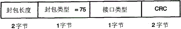
The form of Figure 27 specification interface type transmission Request Packet.
Figure 28 specification interface type is confirmed the form of package.
Figure 29 illustrates the form of carrying out type transmission package.
Figure 30 illustrates that the forward voice-grade channel enables the form of package.
Figure 31 illustrates the form of reverse audio sample rate package.
Figure 32 illustrates the form of digital content protection expense package.
Figure 33 illustrates that transparent color enables the form of package.
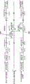
Figure 34 illustrates the form of round trip delay measurements package.
The sequential of the event of Figure 35 explanation during round trip delay measurements package.
Figure 36 explanation is applicable to implement the sample enforcement of CRC generator of the present invention and checker.
Figure 37 A illustrates the sequential of the CRC signal of the equipment that is used for Figure 36 when sending data packet.
Figure 37 B illustrates the sequential of the CRC signal of the equipment that is used for Figure 36 when the receive data package.
Figure 38 explanation is at the treatment step without the exemplary service request in the contention situation.
Figure 39 explanation is at the treatment step of establishing after link restarts sequence and begun that begins (link start) with link and have the exemplary service request in the situation of contention.
How Figure 40 explanation encodes to transmit a data sequence with DATA-STB.
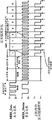
Figure 41 explanation is applicable to generate DATA and STB signal and follow the circuit that recovers data in client from the input data at the main frame place.
Figure 42 explanation is applicable to implement driver and the terminating resistor of an embodiment.
Figure 43 illustrates that client obtains step and the signal level that adopts when when service and main frame provide this kind service from main frame.
The relative spacing of Figure 44 explanation between the transformation on Data0, other data wire (DataX) and the select lines (Stb).
The existence of the operating lag that Figure 45 explanation can occur when forbidding host driver after main frame is transmitting a package.
Figure 46 explanation is enabled existing of operating lag that host driver can occur when transmitting a package when main frame.
Figure 47 illustrates at main frame receiver input, the relation between the sequential of the data that are transmitted and the frontier and rear of strobe pulse.
Figure 48 illustrates switching characteristic and by the corresponding client output delay of reverse data timing sequence generating.
Figure 49 illustrates and uses state machine to implement synchronously used signal treatment step and the high-level diagram of condition.
Figure 50 explanation forward and the reverse path in the system that adopts MDDI carries out the typical delay amount that can run into when signal is processed.
Figure 51 illustrates marginal round trip delay measurements.
Figure 52 illustrates that reverse link data rate changes.
Figure 53 illustrates that the reverse rate divisor is than the diagrammatic representation of the value of forward link data rate.
The step that Figure 54 A and 54B explanation are taked in interface operation.
Figure 55 has illustrated the general survey of interface equipment processing package.
Figure 56 has illustrated the form of forward link package.
Figure 57 has illustrated propagation delay in the I type LI(link interface) and the representative value of deflection.
Figure 58 has illustrated Data, Stb and the clock recovery sequential of exemplary signal processing on I type link via interface.
Figure 59 has illustrated propagation delay in II type, III type or the IV type LI(link interface) and the representative value of deflection.
Figure 60 A, 60B and 60C have illustrated the different possibilities of two data signals and MDDI_Stb sequential relative to each other, are respectively desirable, early and slow.
Figure 61 illustrates and cooperates the I interface pin that type/II type interface uses to dispose exemplary connector.
Figure 62 A and 62B illustrate respectively possible MDDI_Data and the MDDI_Stb waveform for I type and II type interface.
Figure 63 has illustrated and has used state machine to implement synchronously used substituting signal treatment step and the high-level diagram of condition.
Figure 64 has illustrated the exemplary relative timing between the sequential of the circulation of a series of clocks and various reverse link package position and divider value.
Figure 65 has illustrated that exemplary error code transmits processing.
Figure 66 has illustrated that being applicable to error code transmits the equipment of processing.
Figure 67 A has illustrated that the error code that is used for heavily loaded code transmits processing.
Figure 67 B has illustrated the error code transmission processing that is used for receiving code.
Figure 68 A has illustrated that being used for main frame opens the treatment step that wakes up of beginning.
Figure 68 B has illustrated that being used for client opens the treatment step that wakes up of beginning.
Figure 68 C has illustrated is having in the situation of contention the main frame of being used for and client open the treatment step that wakes up of beginning.
Embodiment
I. general introduction
Cardinal principle purpose of the present invention provides a kind of mobile display digital interface (Mobile Display DigitalInterface) as discussed below (MDDI), and it causes or provides data link or the passage of a kind of permission by using " serial " type to carry out the saving cost of high speed or the transmission of hypervelocity data, the transfer mechanism of low-power consumption via the short distance communication link between host apparatus and display unit.This mechanism is applicable to be engaged in when being connected to portable computer, wireless communication apparatus or entertainment device such as the display element of wearable minisize display (glasses or projecting apparatus) or device useful especially micro connector and soft Thin cable and implements together.
An advantage of embodiments of the invention provided a kind of low complex degree, low cost, high reliability, with environment for use no-float and very firm while data transferring technique very flexibly still.
The present invention can be used for the various situations mass data that will generally be used for audio frequency, video or multimedia application with two-forty of getting off and passes on or be sent to the client display or present device from the main frame or the source apparatus that generate or store these data.It is that data are sent to such as miniature video screen or the wearable minisize display unit visual display unit of (such as being the glasses that contain lenses for compact projection and screen or the form of the helmet) from portable computer or radio telephone or modulator-demodulator that a typical case who hereinafter discusses uses, or data are sent to client terminal device in these assemblies from main frame.The meaning namely, from the processor to the inner screen or other present element.
The feature of MDDI or characteristic are so that it is independent of concrete Display Technique.This is the high-speed data transfer mechanism of the high flexible of a kind of internal structure that can not consider data function aspects of also not considering the data of its enforcement or order.This allows to adjust the sequential of the data packet that transmits with the characteristic that is adapted to particular display device or the Voice ﹠ Video requirement that is adapted to unique display requirement of some device or satisfies the combination of some A-V system.As long as can follow selected agreement, described interface is display element or client terminal device irrelevant (agnostic).In addition, total serial link data or data transfer rate can change at several orders of magnitude, thereby allow communication system or host apparatus designer optimized cost, power requirement, client terminal device complexity and display unit renewal rate.
The data-interface that provides mainly is for transmitting a large amount of high data rates via " wired " signal link or mini-cable.Yet, some is used and also can utilize Radio Link (comprising the link based on optics), keeps practicality as long as it is configured to use the same packet that is used for described interface protocol developed and data structure and can enough keeps desirable transmission level under the low condition in power consumption or complexity.
II. environment
In Figure 1A and 1B, can see typical an application, wherein show respectively and display unit 104 and 106 and portable or kneetop computer 100 and radio telephone or the PDA device 102 of audio reproduction system 108 and 112 communication datas.In addition, Figure 1A showed to the potential connection of larger display or screen 114 or projecting apparatus 116, and for purpose clearly, it only is showed among the figure, but can be connected to wireless device 102 equally.Described wireless device can be just watched for the end user who presents to subsequently wireless device and/or is listened in receive data or previous multimedia type data of having stored specified quantitative in memory component or device.Because typical wireless device is for voice and plain text communication in the time of majority, it conveys to information with quite little display screen and simple audio system (loud speaker) user of device 102.
This makes and presents data more complicated or " enriching " and become a kind of so useful or not happy experience.Therefore, industry is being developed other mechanism and device and is come to end user's presentation information and the joyful or positive experience of the minimum degree of expectation is provided.
Such as before hereinbefore discussion, the display unit of developing some types is with the end user's presentation information to device 100.For example, one or more companies have developed many covers with image projection auto levelizer user's the wearable glasses that provide vision to show at the moment.When this kind device was properly oriented, it is " projection " amplitude ratio virtual image of providing the much bigger eyes by the user of element of vision output to see effectively.That is to say that a very little projection element allows user's eyes " to see " than the much bigger image of ratio in the situation of typical lcd screen and analog.Use larger virtual screen image also to allow to use than the much higher image of resolution in the situation of more limited lcd screen display.Other display unit can include, but is not limited to small LCD screen or various flat panel displaying element, be used for image projection to lip-deep projecting lens and display driver, etc.
Also can there be the additional element that is connected to wireless device 102 or computer 100 or is associated with its use, output offered another user or to offer another signal be transferred to again other local or stored device.For example, data can be stored in the flash memory, with optical form storage (for example, use can be write the CD media) or be stored in the magnetic medium (such as in tape recorder and similar device) for using subsequently.
In addition, present many wireless devices and computer have built-in MP3 music decoding capability and other senior sound equipment decoder and system.Portable computer all has CD and DVD ability to play usually, and some also has the small, dedicated flash memory reader to receive pre-recorded audio file.Following the problem that has these abilities and come is the potential rich experience that provides characteristic greatly to increase of digital music file, but this only could realize in the enough fast situation of decoding and playing process.Also be the same for digital video file.
Showed the external loudspeaker 114 that is used for assisting sound reproduction among Figure 1A, it also can be accompanied with extra element, such as assisting woofer or being used for " surround sound " loud speaker that front and rear sound throws.Simultaneously, be built in loud speaker or earphone 108 are shown as in the support frame or mechanism of microform display device 106 of Figure 1B.As will be understood, other audio frequency or sound reproduction element be can use, power amplification or sound building mortion comprised.
In a word, discuss as mentioned, when hope sends high-quality or high resolution image data and high quality audio information or data signals to end user from a data source via one or more communication links 110, need High Data Rate.That is to say, transmit link 110 and obviously be a potential bottleneck of data communication as discussed above, and limited systematic function, because existing transfer mechanism does not reach common desired High Data Rate.Discuss for example as mentioned, with regard to such as the 1024 higher image resolutions of taking advantage of 1024 pixels, when every pixel color depth is 24-32 position and data transfer rate when being 30fps, data transfer rate can reach above 755Mbps or higher speed.In addition, these images may be that the part as multimedia presentation provides, described multimedia presentation comprises voice data and relates to potential extra signal or various command, control or the signal of interactive game or communication, thereby further increased data volume and data transfer rate.
Be that requirement is set up data link with still less cable or interconnection equally significantly, this means that the mobile device that is associated with display can be easier to use, and more likely adopted by more people.This uses a plurality of devices particularly correct when setting up a kind of complete audio frequency-visual experience common, and all the more so when the quality level of display and audio output device increases.
Unfortunately, described higher data transfer rate has surmounted the prior art level that can be used for transmitting data.Need a kind of technology for transmitting link or communication path in the data that present between element and the data source to transmit data with two-forty, it should contain following characteristics: stably () low-power, light weight and the simple and cheap as far as possible construction of cable.The applicant has developed a kind of innovative techniques, or method and apparatus, realize these and other target with allow a series of movements, portable or or even fixed position device with high data transfer rate data are sent to desired display, miniscope or audio frequency conveying element, still keep simultaneously desirable low-power consumption and complexity.
III. two-forty digital data interface system configuration
In order to create and effectively utilize a kind of device interface of novelty, designed a kind of signal protocol and system configuration of using the low-power signal that high rate of data signalling is provided.Described agreement is based on a package and shared frame the structure structure of agreement (or link together to form), the order or the operating structure that are used for communication previously selected one group of data or data type and are applied to described interface.
A. general introduction
Be called main frame and client by the MDDI link connection or via the device of MDDI link communication, client is certain type display unit normally.Data forward from the main frame to the display is advanced (being called forward traffic or link), and is advanced (oppositely traffic or link) by the data back from the display to the main frame that main frame is enabled.This is illustrated in the basic configuration shown in Figure 2.In Fig. 2, main frame 202 uses a both-way communication passage 206 to be connected to client 204, and described communication channel 206 is illustrated as and comprises a forward link 208 and a reverse link 210.Yet these passages are to be formed by the one group of conductor that shares, and its data transmit effectively to be switched between forward link operation or reverse link operations.
Discuss such as this paper other parts, main frame comprises one of some types of devices that can benefit from use the present invention.For example, main frame 202 can be and is hand-held computer, kneetop computer or the similar portable computer of the form of mobile computing device, and it can be PDA, paging equipment, perhaps one of multi radio words or modulator-demodulator.Perhaps, main frame 202 can be portable entertainment or presents device, such as portable DVD player or CD Player or game device.Simultaneously, client 204 can comprise various being applicable to the device of end user's presentation information.For example, be incorporated into glasses miniscope, in be built in projection arrangement in cap or the helmet, in be built in small screen or or even holographic element (such as in vehicle window or windshield) or various loud speaker, head-telephone or be used for presenting the sound system of high-quality sound equipment or music in the vehicle.Yet, the those skilled in the art will be easy to understand and the invention is not restricted to these devices, exist many being expected to provide other device high-quality image and sound equipment and that suggestion is used to the end user aspect storage and transportation aspect or presenting when playing on the market.The present invention is applicable to be increased in the data throughout between the various devices, experiences required High Data Rate to adapt to the user who realizes ideal.
B. interface type
The MDD interface is envisioned for five kinds or the more significantly different actual interface type of processing in communication and computer industry.Simply be denoted as I type, II type, III type, IV type and U-shaped with these actual interface types this moment.
The I class interface is configured to 6 lines (6-wire) (conductor) interface, and this makes it be applicable to movement or radio telephone, PDA, e-book (e-Book), electronic game, reach portable electronic device (such as CD Player or MP3 player), reach the device based on the E-consumer technology of similar type.The U class interface is configured to 8 lines (8-wire) (conductor) interface, and it more is applicable to kneetop computer, notebook computer or the desktop personal computer and similar device or the application that do not need quick update displayed and do not have built-in MDDI link controller.This interface type also can be identified by employed extra two-wire USB (USB) interface, and it is extremely helpful for the existing operating system or the software support that adapt on most PC.U-shaped interface also can be used in a kind of only USB (USB-only) pattern, wherein display only has one and (for example is connected to computer or similar device, the consumer electronic device of standard USB port is equipped with, such as digital camera or video player) on the USB connector of standard USB port.
II type, III type and IV type interface are applicable to Performance Monitor or device, and come to transmit for data signals provides adequate shielding and low-loss with the larger more complicated wiring with extra twisted-pair feeder type wire.
The transmission of I type interface can comprise demonstration, video, control and limited news makes the signal of information, and is generally used for not requiring the device of high-resolution full rate video data.This class interface is mainly used in the device such as portable radio, wherein usually is not used for connecting and transmitting the usb host (USB host) of signal.In this configuration, mobile device is MDDI master's device and serves as " master control (master) " that control is derived from the communication link of main frame that its general transmission shows that data are to client (forward traffic or link).
In this interface, main frame is enabled at described main frame place from client communication data (oppositely traffic or link) by a special command or packet type being sent to client (allowing it to send to main frame in regulation duration inner connecting tube bus (link) and with data as reverse package).This is illustrated among Fig. 3, and the package that wherein a class is called encapsulation package (hereinafter discuss) is used for adapting to transmitting link to be uploaded and send reverse package, thereby creates reverse link.For the host computer polls display predetermined by main frame with the time interval that obtains data and distributed, and based on the requirement of each application-specific.These class half-duplex bidirectional data are transmitted in and can't transmit in the situation of information or data especially favourable from client with USB port.
U-shaped interface transmits the signal that is very suitable in the on knee and desk-top application, and in these were used, USB interface was subject to the extensive support of a large amount of mainboards or other hardware and operating system software.The use of newly-increased USB interface has allowed use " plug and play " characteristic and easy application deployment.Comprise the general two-way flow that USB has also allowed order, state, voice data etc., the while can be used twisted-pair feeder with low-power and be transmitted with the Audio and Video data of client terminal device as target at a high speed.As discussed below, can come delivering power with other wire.Use the embodiment of the invention of USB interface to allow to transmit via the high speed of one group of conductor, mainly connect to implement news order and control via USB simultaneously, it can close and consume little power when not using.
USB interface is very widely used standard in the modern personal computer equipment, and the details of USB interface and its operate in the technique and know therefore no longer explanation herein.With regard to USB interface, the communication garment between main frame and the display is from universal serial bus specification, revised edition 2.0 (Universal Serial Bus Specification, Revision 2.0).USB is that main news make passage and may is that main frame comes opinion to ask client via MDDI serial data signal alternatively in the application of the U-shaped interface of use of voice backward channel therein.
Having the ability to carry out Performance Monitor that HDTV type or similar high-resolution show, to require speed be the data flow of about 1.5Gbps, so that support full-motion video (full-motion video).II type interface is supported High Data Rate by 2 of parallel transmissions, and III type interface is supported High Data Rate by 4 of parallel transmissions, and IV type interface is supported High Data Rate by 8 of parallel conveys.The employed agreement of MDDI allow each I type, II type, III type or IV type main frame usually with arbitrary I type, II type, III type or IV type client or display through consultation the highest spendable possible data rate come communication.The ability of the most incompetent device or the performance that available characteristic is used for setting link will be can be described as.Usually, even can both use the system of II type, III type or IV type interface for main frame and client, main frame and client still begin operation with I type interface.Main frame is then determined the ability of destination client or display, and so that the suitable mode of application-specific is consulted the transmission (hand-off) of one to II type, III type or IV pattern formula or reconfigured operation.
Main frame generally may use suitable link layer protocol (hereinafter further discussing), and may slow down at any time (stepdown) or again operation be reconfigured to a slow speed mode and save power or acceleration (step up) and support the transmission of more speed to one than fast mode, such as being used for more high-resolution displaying contents.For example, when display system from such as the electrical source exchange of battery during to AC power or switch to lower or during the high-resolution form when the source of display media, main frame can change display mode, can consider that perhaps these or other being combined of conditioned disjunction event changes demonstration or data transfer mode based on this.
System also may use a kind of mode communication data in one direction, and uses another kind of mode communication data at other direction.For example, IV type interface modes can be used for two-forty data being sent to display, and when using I type or U-shaped pattern when transferring data to host apparatus from ancillary equipment (such as keyboard or indicator device).
C. actual interface structure
Showed the substantially layout for device or the link controller of between main frame and client terminal device, setting up communication in the Figure 4 and 5.In Figure 4 and 5, MDDI link controller 402 and 502 is shown as and is installed in the host apparatus 202, and MDDI link controller 404 and 504 is shown as and is installed in the client terminal device 204.As previously mentioned, main frame 202 is connected to client 204 by the both-way communication passage 406 that comprises a series of conductors.Such as hereinafter discussion, main frame and client link controller all can be used as with the integrated circuit of single circuit design and make, wherein said circuit design can through set, adjust or programming to respond as console controller (driver) or client controller (receiver).This provides the low cost of being brought by fairly large manufacturing single circuit device.
In Fig. 4, also showed usb host device 408 and the USB client terminal device 410 of the U-shaped interface version that is used for enforcement MDDI.Be used for implementing the circuit of these functions and installing and know at technique, and no longer describe in detail herein.
In Fig. 5, MDDI link controller 502 be shown as be installed in host apparatus 202 ' in and MDDI link controller 504 be shown as be installed in client terminal device 204 ' in.As previously mentioned, main frame 202 ' by the both-way communication passage 506 that comprises a series of conductors be connected to client 204 '.Discuss as mentioned, host link controller and client link controller all can be made with single circuit design.
Also illustrated in the Figure 4 and 5 via MDDI link or employed practical conductor and the signal that between main frame and client (such as display unit), transmits.As shown in Figures 4 and 5, be used for via MDDI transmit the main path of data or mechanism used be denoted as MDDI_Data0+/-and MDDI_Stb+/-data signals.Each low-voltage data signals that transmits via the differential pair wire in the cable naturally of these signals.For send via interface each, MDDI_Data0 to or MDDI_Stb on only have a transformation.This be based on voltage transfer mechanism but not based on electric current, so quiescent current consumption approaches zero.Main frame is driven into the client display with the MDDI_Stb signal.
Although data can be via MDDI_Data to flowing (anticipate namely, it is two-way transfer path) at forward and inverse direction, main frame is main controller or the controller of data link.MDDI_Data0 and MDDI-Stb signal path are operated under the difference modes with the maximization vulnerability to jamming.The data transfer rate of the signal on these circuits determined by the speed of the clock pulse that main frame sends, and at about 1kbps until variable in 400Mbps or the larger scope.
II type interface except the data of I type externally also comprise extra data to or conductor or path, be called MDDI_Data1+/-.III type interface except the data of II type interface externally also comprise two extra data to or the signal path, be called MDDI_Data2+/-and MDDI_Data3+/-.IV type interface except the data of III type interface externally also comprise four extra data to or the signal path, be called: MDDI_data4+/-, MDDI_Data5+/-, MDDI_Data6+/-and MDDI_Data7+/-.In each configuration in above-mentioned interface configuration, main frame can use the line of being appointed as MDDI_Pwr and MDDI_Gnd to or signal power is sent to client or display.
The general a kind of transmission type that only can be used for U-shaped configuration is that MDDI USB connects or the signal path.MDDI USB connects the secondary path that comprises for communication between main frame and client display.In some applications, sending some information with lower data rate between main frame and client may be more favourable.Use USB transmission link allows not have the MDDI link controller but has usb host or the device of limited master capability and the compatible client of the MDDI that is equipped with U-shaped interface or display communication.Can have via the information instances that USB interface is sent to display effectively: static bitmap, digital audio stream, indicator device data, keyboard data and control and state information.Also can implement with main MDDI high-speed serial data path via the function that USB interface is supported.Although data defined above (package that vide infra) can send via the USB style interface, but the requirement that and then serial data is unified into the package form of (back-to-back) is not suitable for this kind USB interface, uses the requirement of the package of supporting the transmission of MDDI type not to be suitable for this kind USB interface yet.
The summary of the signal that transmits between main frame and client (display) via the MDDI link hereinafter, has been described in Table I according to interface type.
Table I

The general wiring nominal length that is used for implementing above structure and operation is about 1.5 meters and comprise three twisted pair conductor, and each root is again multiply 30AWG wire.Reel or otherwise form a paillon foil shielding coating at described three twisted-pair feeders, as extra drain wire.Twisted-pair feeder and shielding row disturb conductor and end in the Display connector, and described screen is connected to the screen of display (client) simultaneously, and as knowing in this technology, have an insulating barrier that covers whole cable.Described wire is paired into: MDDI_Gnd and MDDI_Pwr; MDDI_Stb+ and MDDL_Stb-; MDDI_Data0+ and MDDI_Data0-; MDDI_Data1+ and MDDI_Data1-; Etc..The nominal cable size is about 3.0 millimeters, and nominal impedance is 85 ohm ± 10%, and nominal DC resistance is per 1000 feet 110 ohm.The signal propagation velocity answers nominal ground to be 0.66c, should be less than about 8.0 nanoseconds via the maximum delay of cable.
D. data type and data transfer rate
Whole users experience and the interface of range of application in order to realize being applicable to, and mobile digital data-interface (MDDI) provides various displays and demonstration information, Audio-Frequency Transformer, keyboard, indicator device and many other can be integrated into mobile display device or with the input unit of mobile display device collaborative work, together with control information and the support of making up thereof.The various potential traffic types that the MDD interface is transmitting between main frame and client on forward link direction or the reverse link direction through being designed to be able to adapt to the cable that uses minimal amount or conductor.Stream and asynchronous flow (renewal) are all supported synchronously.As long as the data transfer rate that amounts to is less than or equal to the maximum MDDI link rate of wanting, just may use many combination of data types.These can include, but is not limited to those projects of listing in the hereinafter Table II and Table III.
Table II

Table III

Described interface is not changeless but extendible, so that it can support various information " type " transmission of (comprising that the user defines data), to realize the flexibility of system in future.The instantiation of the data that will comprise is: full-motion video, form are full frame or part of screen bitmap field (bitmap field) or compressed video; The static bitmap of low rate is with saving power and reduce implementation cost; The audio compressed data of various resolution or speed or PCM; Indicator device position and selection, and be used for still user's definable data of undefined ability.Also these data can be transmitted with arrangement for detecting ability or setting operation parameter together with control or state information.
The present invention has advanced and has been used for the technology that data transmit, and includes, but is not limited to: watch film (video shows and audio frequency); Use has the PC that limited individual inspects (personal viewing) (graphic alphanumeric display is sometimes with the Audio and Video combination); Operate video games at PC, game machine or personal device (moving picture shows or artificial Audio and Video); View Internet; Type of service is visual telephone (two-way low rate video and audio frequency), be used for to take the camera of static number photo or be used for the device of the camcorder of picked-up digital video image; And the productivity ratio that is used for mobile phone, smart phone or PDA strengthens or recreational use.
The Mobile data interface of hereinafter discussing is with regard to via the communication that generally is configured to Wireline or cable class link or transmit link and a large amount of A-V categorical datas aspect is provided.But, it is evident that described structure signal, agreement, sequential or transfer mechanism can be through adjusting so that the link of form as optics or wireless medium (if it can keep desirable data transmission level) to be provided.
MDD interface signal will be called common frame (Common Frame) concept (CF) and be used for basic signal protocol or structure.Use common frame institute based on thought be that synchronous data flow for the while provides lock-out pulse.Display unit can use this common frame speed as time reference.Low CF speed increases channel efficiency by reducing in order to the expense of transmitting sub-frame header.On the other hand, high CF speed has reduced the stand-by period, and it is less to be allowed for the elastic data buffering area of audio sample.The CF speed of property interface of the present invention is the capable of dynamic programming, and the synchronous stream that can be set in being used for application-specific is a value place in suitable many values.That is to say that on demand, the CF value is through selecting to adapt to most particular display device and host configuration.
Showed the most possible general required byte number (it is capable of regulating or programmable) of every common frame that is used for the synchronous data flow of certain application (such as the wear-type miniscope) in the Table IV.
Table IV

By using simple M/N counter structure able to programme, be easy to obtain the mark count value of every common frame byte.For example, be the frame of 26 bytes behind the frame by transmitting two 27 bytes and each frame, can realize the count value of every CF 26-2/3 byte.Can select less CF speed to produce every CF integral words joint.Yet, in general, within being used for implementation section or all integrated circuit (IC) chip of the present invention or electronic module, can be less than the required zone of larger audio sample fifo buffer with the zone that the simple M/N counter of hardware implementation is required.
The illustrative application that the impact of different pieces of information transfer rate and data type is described is karaoke OK system.In Karaoke, system user attends by the music video program and sings.The lyrics of song are presented at the bottom of screen, the user are known the lyrics that will sing and the general opportunity of singing.This application requirements figure upgrades not frequently video demonstration, and user's voice are mixed with stereo audio stream.
If supposition common frame speed is 300Hz, so each CF will by via forward link to 92 of display unit, the audio content of the video content of 160 bytes and 588 bytes is (based on 147 16 samples, stereo) form, and the voice of average 29.67 (26-2/3) byte are sent back to mobile karaoke machine from microphone.Between main frame and display, send asynchronous package.(some) bytes that are used for miscellaneous control and status command that this comprises the graph data (1/4th screen heights) of maximum 768 bytes and is less than about 200 bytes.
Table V has been showed how in the common frame distribute data that is used for the Karaoke example.Employed total speed is selected as about 225Mbps.The speed of slightly high 226Mbps allows to transmit other about 400 byte datas of every subframe, and it allows to use non-frequent control and status message.
Table V
| Key element speed | Byte/CF |
| Music video under 640x480 pixel and the 30fps | 92160 |
| Lyric characters under 640x120 pixel and the 1fps | 768 |
| 44,100sps, stereo, the CD audio frequency under 16 | 588 |
| 8,000sps, monophony, the voice under 8 | 26.67 |
| Sub-frame header | 19 |
| The reverse link expense | 26.67+2*9+20 |
| Total byte/CF | 93626.33 |
| Total speed (Mbps) | 224.7032 |
III. two-forty digital data interface system infrastructure
E. link layer
The data that use MDD interface high-speed serial data signal transmits are comprised of the package stream of the time division multiplexing that links each other.Even the countless certificates of transmitting device will send, the MDDI link controller generally also sends the filler package automatically, therefore, has kept package stream.To the use of simple packet structure so that Audio and Video signal or data flow have reliable synchronous sequence.
Package in groups is comprised in the signal key element or structure that is called subframe, and subframe in groups is comprised in the signal key element or structure that is called media frame.The size out of the ordinary and the data that depend on package transmit purposes, and subframe comprises one or more packages, and media frame comprises one or more subframes.The subframe of the maximum that the agreement of being used by the present invention provides is about 232-1 or 4,294,967,295 bytes, and maximum media frame size just becomes about 216-1 or 65,535 subframes.
As discussed below, a kind of special header package comprises a unique identifier that appears at the beginning of each subframe.Described identifier also is used for when opening the communication of having begun between main frame and the client obtaining at the client terminal device place frame sequential (frametiming).Hereinafter discussed in more detail the link timing acquisition.
In general, when when showing full-motion video, upgrade a display screen for every media frame.Frame rate of display is identical with media frame speed.Depend on desired application, link protocol be supported on the whole display full-motion video or just surrounded by static image than the full-motion video content in the zonule.In some low power mobile application, such as watching webpage or Email, display screen may only need to be upgraded once in a while.In those situations, transmit single subframe and then close or cancel link that to come minimizing power dissipation be favourable.Described interface is also supported the effect such as stereoscopic vision, and processing graphics primitive (graphics primitive).
Adopting the purpose of subframe is so that can transmit periodically the high priority package.This allows the data buffering of synchronous stream simultaneously and minimum and deposits.This is that the present invention is the advantage that procedure for displaying provides, and has allowed a plurality of data flow (high speed communications of video, voice, control, state, indicator device data etc.) to share in fact a shared pathway.It comes transmission information with less signal.It also allows to exist specific action for Display Technique, such as the horizontal synchronization pulse and blanking signal interval (the blanking interval) that are used for the CRT monitor.
F. link controller
MDDI link controller shown in the Figure 4 and 5 is manufactured or be assembled into a kind of enforcement of total digitalization, except being used for receiving the receiver of differential line of MDDI data and gating signal.Yet, or even differential line driver and receiver also can be implemented together in the same numbers integrated circuit with link controller.Do not need analog functuion or phase-locked loop (PLL) to implement hardware for link controller.Except comprising the display interface device for the state machine of link synchronization, host link controller and client link controller have closely similar function.Therefore, the invention provides following real advantage, namely can create a kind of main frame or the design of the Single Controller of client or circuit of can be configured to, this can reduce the manufacturing cost of link controller on the whole.
IV. interface link agreement
A. frame structure
Signal protocol or the frame structure of the forward link communication that is used for the transmission of enforcement package have been described among Fig. 6.As shown in Figure 6, information or numerical data are grouped into the key element that is called package.A plurality of packages are grouped into again together and form the key element that is called " subframe ", and a plurality of subframe is grouped into again and forms together " media " frame.Be the formation of control frame and the transmission of subframe, each subframe begins with a special predefine package that is called sub-frame header package (SHP).
Host apparatus selects to be ready to use in the data transfer rate of specific transmission.This speed can dynamically be changed by the maximum capacity that the Host Based maximum transfer capability of host apparatus or main frame extract other devices that the ability of data and display or data be sent to from data source.
Be designed for (or can) and cooperate the reception client terminal device that MDDI or property signal protocol of the present invention work together can be by host query determining the rate of data signalling (perhaps can use default slower minimum-rate) of its spendable maximum (or current maximum), and available data types and the characteristic supported.This information can use display capabilities package (DCP) to transmit, as further discussed below.Client display device can use described interface to transmit data or communication with previously selected minimum data rates or in a minimum data rates scope with other device, and main frame will use a data transfer rate in this scope to carry out inquiry to determine whole abilities of client terminal device.
Other state informations that can will define the video frame rate ability of the character of bitmap and display in the state package are sent to main frame, so that main frame can get interface configuration is effective or optimum as much as possible, or are desirable under any system constraint.
When in current subframe, not having (more) data packets to be transmitted or when the transfer rate of main frame was not enough to catch up with into the selected rate of data signalling of forward link, main frame sent the filler package.Because each subframe begins with a sub-frame header package, so the end of previous subframe comprises a package (most possibly being a filler package) of just in time filling previous subframe.In situation about lacking for the space of Deta bearer package itself, the filler package will most possibly be last package in the subframe, or at the terminal of the last subframe of the next one and before the sub-frame header package.Guarantee that the remaining space that enough is used for each package that will transmit in described subframe is the task of the control operation in the host apparatus in a subframe.Simultaneously, in case host apparatus opens the transmission of the data packet that begun, main frame must successfully be finished the package of described size in a frame, and does not cause data deficiencies (data under-run) situation.
Aspect of embodiment, the subframe transmission has two patterns.A pattern is for the periodicity subframe pattern of transmitting live video and audio stream.In this pattern, subframe lengths is defined as non-zero.The second pattern is asynchronous or the aperiodicity pattern, but wherein only in the fresh information time spent frame is used for data bitmap is offered display unit.Define this pattern by in the sub-frame header package, subframe lengths being set as zero.When the life cycle pattern, when display has been synchronized with the forward link frame structure, can begin the subframe package and receive.This is corresponding to " synchronously " state that defines according to the state diagram of hereinafter discussing referring to Figure 49 or 63.In asynchronous aperiodicity subframe pattern, after receiving first sub-frame header package, begin to receive.
B. whole packet structure
Be used for systematically discussing the news that the present invention implements and make the form of the packet structure of agreement be set out in hereinafter, please note that described interface is extendible and can adds extra packet structure on demand.According to the function (in other words, the order of its transmission or data) of package in interface, described package is denoted as (or being divided into) different " packet type ".Therefore, each packet type represents the predefine packet structure for a particular packet, and it is used for controlling package and the data that transmit.As will be apparently, package can have previously selected length or have and depends on its function out of the ordinary and length variable or that capable of dynamic changes.Although still can realize identical function, described package also can be with different names, as be accepted in agreement in the standard during can occur in the situation about being changed.The byte or the byte value that are used for various packages are configured to multidigit (8 or 16) signless integer.The summary of having showed the package that used of listing with type sequence in the Table VI with and " type " label.Direction when the transmission of also having indicated package is considered to effective, with and whether be used for U-shaped interface.
Table VI


Package has a common basic structure or minimum one group of territory generally, comprises package length territory, packet type territory, data byte territory and CRC territory, and it illustrates in Fig. 7.As shown in Figure 7, the package length territory comprises the information that form is multidigit or multibyte value, described information specifies the total bit in the package, or its length between package length territory and CRC territory.In one embodiment, 16 or the signless integer of 2 byte wides having stipulated package length contained in the package length territory.The packet type territory is another multidigit territory, and it has indicated contained information type in the package.In an exemplary embodiments, it is the value of 8 or 1 byte wide, and form is 8 signless integers, and stipulated such as display capabilities, transmission, video or audio stream, state, etc. data type.
The third territory is the data byte territory, and it comprises the position or the data that transmit or send as the part of described package between main frame and client terminal device.Specifically define data format according to the specific type of data that transmits for each packet type, and data format can be divided into a series of extra territories, each territory has its oneself call format.That is to say that each packet type will have the defined form for this part or territory.Last territory is the CRC territory, and it comprises 16 cyclic redundancy check (CRC) results that data byte field, packet type territory and package length territory calculated gained, and it is used for confirming the information integrity of package.In other words, the whole package except CRC territory itself is calculated.The general total count value of preserving the crc error that detects of client, and in display request and state package (vide infra), this count value is repaid to main frame.
During transmitting package, take the least significant bit (LSB) of original transmission for beginning and take the highest significant position (MSB) of last transmission as ending up domain transmission.The mode that length is transmitted by least significant byte at first greater than the parameter of a byte is transmitted, this caused the position transmission mode at first transmitted with the wherein LSB that is used for shorter parameter identical for the position transmission mode of length greater than 8 parameter.The position ' 0 ' of the byte of transmitting on the interface under the arbitrary patterns in the data on the MDDI_Data0 signal path and I type, II type, III type or the IV pattern formula is aimed at.
When in the data of controlling for display, transmit data for pel array by the mode of Row Column, as being accustomed in the electronic technology.In other words, appear in the bitmap and at first to be transmitted with the high order end pixel with all pixels in the delegation and the mode of the last transmission of low order end pixel is transmitted in order.After the low order end pixel of delegation was transmitted, the next pixel in the sequence was the high order end pixel of next line.For most displays, the row of pixel is generally with the sequential delivery from the top end of to, although also can comprise other configuration on demand.In addition, when processing bitmap, conventional method (herein also following) is to define a reference point by the upper left corner of bitmap being denoted as position or skew " 0,0 ".Along with the position in the bitmap levels off to respectively right-hand member and the bottom of bitmap, be used for definition or determine that the X of described position and Building Y target value increase.The first row and first row are with exponential quantity zero beginning.
C. package definition
1. sub-frame header package
The sub-frame header package is the first package of each subframe, and has basic structure as shown in Figure 8.As shown in Figure 8, the package of this type is configured to have package length territory, packet type territory, unique word territory, subframe lengths territory, protocol version territory, sub-frame count territory and media frame counting territory, and it is generally by listed order.The package of this type generally is identified as 255 types (0xff hexadecimal) package, and uses the regular length of previously selected 17 bytes.
A byte value is used in the packet type territory, and 3 byte values are used in the unique word territory.One of the common formation of 4 combination of bytes in these two territories has good autocorrelative 32 unique words.In an exemplary embodiments, actual unique word is 0x005a3bff, wherein lower 8 at first as the packet type transmission, and the highest effective 24 transmitted subsequently.
The subframe lengths territory comprises 4 byte information of the byte number of stipulating every subframe.Can be zero with the length setting in this territory, only can transmit a subframe with indication main frame before link is closed to idle condition.Value in this territory can immediately dynamically changed when a subframe is transitioned into next subframe.This ability is applicable to carry out small sequential adjustment in lock-out pulse, to adapt to synchronous data flow.If the CRC of sub-frame header package is invalid, link controller should be estimated with the subframe lengths of the last sub-frame header package that is known as the length of current subframe so.
The protocol version territory comprises 2 bytes of the employed protocol version of regulation main frame.The protocol version territory is set as ' 0 ' to be come first or current version of agreement be defined as and is using.Along with time lapse when having produced redaction, this value will change.The sub-frame count territory comprises 2 bytes, and it has stipulated a sequence number, the number of sub frames that the indication of described sequence number has been transmitted from the beginning of media frame.It is zero sub-frame count that the first subframe of media frame has.Last subframe of media frame has the value for n-1, and wherein n is the number of sub frames of every media frame.Note that sub-frame count must also be set as zero so if subframe lengths is set as zero (indication aperiodicity subframe).
Media frame counting territory comprises 3 bytes, and it has stipulated a sequence number, the number of the media frame that described sequence number indication has been transmitted from transmitting the beginning of current media project or data.It is zero media frame counting that the first media frame of media item has.Before the first subframe of each media frame, the media frame counting adds 1, and after having used maximum media frame counting (for example, media frame number 224-1=16,777,215), the media frame counting turns back to zero.The media frame count value generally can be at any time by host reset to adapt to the needs of final application.
2. filler package
The filler package is when the package that is sent to or transmits when forward or reverse link do not have out of Memory to send from client terminal device.Suggestion filler package has a minimum length, in order to have maximum flexibility when sending when needed other package.At the place, end of subframe or reverse link encapsulation package (vide infra), link controller is set the size of filler package to fill up remaining space, in order to keep the package integrality.
The format and content of filler package is showed among Fig. 9.As shown in Figure 9, the package of this type is configured to have package length territory, packet type territory, filler byte field and CRC territory.The package of this type generally is identified as the O type, and is instructed in the 1 byte type field.The full zero value that position in the filler byte field or byte comprise variable number is to allow the filler package by being wanted length.Minimum filler package does not comprise byte in this territory.That is to say that described package only is comprised of package length, packet type and CRC, and use previously selected 3 byte regular lengths.
3. video flowing package
Video flowing package carrying video data is with the zone that is generally rectangle of update displayed device.The size in this zone can be as small as single pixel or large to whole display.The stream that may have simultaneously the almost infinite number that shows, it is by system resource constraints because show a required institute of stream have powerful connections (context) all be contained in the video flowing package.The form of video flowing package (video data format descriptor symbol) is illustrated among Figure 10.As shown in Figure 10, the package of this type (2 byte) territory that is configured to have package length, packet type territory, video data descriptor field, display properties territory, X left side marginal area, Y top margin marginal area, X the right marginal area, Y base marginal area, X and Y domain, pixel counts territory, parameters C RC territory, pixel data field and CRC territory.This type of package generally is identified as 1 type, and is instructed in the 1 byte type field.
The common frame concept of above discussing is a kind of effective means that minimizes the audio buffer size and reduce the stand-by period.But, for video data, may be necessary that pixel with a frame of video is dispersed in a plurality of video flowing packages in the media frame.Same very possible pixel in single video flowing package is not just corresponding to a perfect rectangular window on the display.For the exemplary video frame rate of per second 30 frames, per second has 300 subframes, thereby causes 10 subframes of every media frame.If 480 row pixels are arranged in each frame, each the video flowing package in each subframe will comprise 48 row pixels.In other cases, the video flowing package not necessarily comprises the capable pixel of integer.This for the number of sub frames of every media frame wherein can not be equably except other frame of video size of row (the being also referred to as video line) number of every frame of video be correct.Although the video flowing package not necessarily comprises the capable pixel of integer, each video flowing package generally must comprise an integer pixel.This respectively has an above byte or its in pixel is important when being in as shown in figure 12 the compressed format.
Showed the format and content that adopts for the operation that realizes exemplary video data descriptor field as indicated above among Figure 11 a-11d.In Figure 11 a-11d, video data format descriptor symbol territory comprises 2 bytes that form is 16 signless integers, and described integer has been stipulated the form of each pixel in the pixel data (Pixel Data) in the current stream in the current package.Different video stream package may use the different pixels data format, that is to say in the video data format descriptor symbol and use different values, and similarly, a stream (zone of display) can change its data format immediately.The video data format descriptor symbol has only defined the pixel format that is used for current package, and it does not also mean that certain constant form will continue the whole presence for particular video stream.
How Figure 11 a to 11d has illustrated the coding video frequency data format descriptor.As used in these figure, and in this embodiment, when position [15:13] is when equaling ' 000 ' shown in Figure 11 a, video data just is comprised of the array of include monochrome pixels, and wherein the figure place of every pixel is accorded with 3 to 0 definition of word by video data format descriptor.11 to 4 are set as zero in the case.As position [15:13] when equaling ' 001 ', shown in Figure 11 b, then video data is comprised of colorful array of pixels, and described pixel is respectively stipulated a kind of color by a color map.In this case, video data format descriptor accords with the bits number of 5 to 0 every pixels of definition of word, and 11 to 6 are set to zero.As position [15:13] when equaling ' 010 ', shown in Figure 11 c, then video data is comprised of colorful array of pixels, and wherein the bits number of every pixel redness is by 11 to 8 definition, the bits number of every pixel green is by 7 to 4 definition, and the bits number of every pixel blueness is by 3 to 0 definition.In the case, the sum of the position in each pixel is the summation of number for the position of red, green, blue.
But, as position [15:13] when equaling ' 011 ', shown in Figure 11 d, then video data is by having forming for the video data array of 4:2:2 form of brightness and chrominance information, wherein the bits number of every pixel intensity (Y) is by 11 to 8 definition, the bits number of Cr component is by 7 to 4 definition, and the bits number of Cb component is by 3 to 0 definition.The sum of the position in each pixel is the summation for the number of the position of red, green and blue.Half speed with the speed that sends Y sends Cr and Cb component.In addition, video sample in the pixel data of this package part is organized as follows: Yn, Crn, Cbn, Yn+1, Yn+2, Crn+2, Cbn+2, Yn+3 ..., wherein Crn and Cbn are associated with Yn and Yn+1, and Crn+2 and Cbn+2 be associated with Yn+2 and Yn+3, etc.If there is odd number of pixels (X right hand edge-X left hand edge+1) in the delegation in current stream, will be the Y value of first pixel of next line after the Cb value corresponding to last pixel in every delegation then.
For four forms of all shown in the figure, stipulated whether compress or the byte-aligned pixel data of pixel data sample for 12 that are denoted as " P ".Value ' 0 ' indication each pixel in described pixel data field in this territory is byte-aligned with a MDD interface byte boundary (byte boundary) with each color in each pixel.Each pixel in value ' 1 ' the indication pixel data field and each color in each pixel are that the color in last pixel or a pixel is compressed to, thereby eliminate untapped position.
The first pixel of the first video flowing package that is used for the media frame of particular display window will be gone to the upper left corner by X left hand edge and the definition of Y top edge of described stream window, and the next pixel that receives is placed in the next location of pixels among the colleague mutually, etc.In this first package of media frame, the X initial value will equal the X left hand edge usually, and the Y initial value will equal the Y top edge usually.In the subsequently package corresponding to the same screen window, X and Y initial value will be set to the location of pixels of a upper pixel that sends in the video flowing package that usually and then transmits in the screen window usually in last subframe.
4. audio stream package
The audio stream package has carried and will broadcast or be used for the independently voice data of audio rendering device by the audio system of display.Different audio data streams can be allocated for the voice-grade channel that separates in the sound system, for example: depend on the type of employed audio system, be left front, right front, central, left back and right back passage.The head-telephone of processing for the space acoustics signal that contains enhancing provides a whole set of voice-grade channel.The form of audio stream package has been described among Figure 13.As shown in Figure 13, the package of this type is configured to have package length territory, packet type territory, voice-grade channel ID territory, audio sample counting territory, every sample position and compression domain, audio sample rate territory, parameters C RC territory, digital audio-frequency data territory and voice data CRC territory.In one embodiment, this type package generally is identified as 2 type packages.
Every sample position and compression domain comprise 1 byte that form is 8 signless integers, and it has stipulated the compressed format of voice data.The general form that adopts is the bits number of 4 to 0 every pcm audio samples of definition.Then whether stipulate the compression digital audio frequency data sample for 5.The audio samples of compression and the difference between the byte-aligned audio samples have been described among Figure 14.Each pcm audio sample and a MDDI interface byte boundary byte alignment in value ' 0 ' the designation number voice data territory, and value ' 1 ' indicates each continuous pcm audio sample to be compressed with respect to last audio samples.This is effective when only value (bits number of every pcm audio sample) of definition is not eight multiple in 4 to 0.7 to 6 are preserved for following purposes and generally are set as null value.
5. keep the stream package
In one embodiment, kept packet type 3 to 55, be defined for the future version of packetizing protocol or the stream package of variant with the needs of the various application that are used for to run into by meeting.Again, this is that technology and the system that faces continuous variation makes the more flexible and more useful aspect of described MDD interface with other technologies are compared.
6. the user defines the stream package
Eight data stream types that are called 56 to 63 types are preserved for being defined to cooperate by equipment manufacturers the proprietary application of MDDI link use.These data stream type are called the user and define the stream package.Video flowing package carrying video data is to upgrade a rectangular area of (or not upgrading) display.Being used for the stream parameter of these packet type and data will leave the particular device manufacturer of seeking with them for and define.Illustrated among Figure 15 that the user defines the form of stream package.As shown in Figure 15, this class package is configured to have package length territory (2 byte), packet type territory, stream ID territory, stream parameter field, parameters C RC territory, flow data territory and flow data CRC territory.
7. color map package
The color map package has been stipulated in order to present the content for the color map look-up table of the color of display.Some application may require the color map larger than the data volume that can transmit in single package.In these cases, can transmit a plurality of color map packages, by using skew and length field hereinafter described, each package has different subsets of color map.The form of color map package has been described among Figure 16.As shown in Figure 16, the package of this type is configured to have package length territory, packet type territory, color map size of data territory, color map offset domain, parameters C RC territory, color map data field and data CRC territory.This type of package generally is identified as 64 type packages.
8. reverse link encapsulates package
In an exemplary embodiments, use reverse link encapsulation package oppositely transmitting data.Send a forward link package, and in the change midway of this package or reverse MDDI link operation (direction of transfer), so that can oppositely send package.The form of reverse link encapsulation package has been described among Figure 17.As shown in Figure 17, the package of this type is configured to have package length territory, packet type territory, reverse link flag territory, reverse length field, parameters C RC territory, reverses 1 territory, reverse data packet domain, reaches and reverse 2 territories.The package of this type generally is identified as 65 type packages.
The MDDI link controller moves with a kind of particular form when sending reverse link encapsulation package.The MDD interface has one always by the gating signal of host driven.As if main frame is so that it moves for the reverse of reverse link encapsulation package and zero mode of each transmission of reverse data package.Main frame described two reverse time durations and the time durations that minute is used in the reverse data package in each boundary (bit boundary) locate bifurcation trigger a MDDI_Strobe signal (this be with the full remainder of its transmission according to the time identical action).Main frame is forbidden its MDDI data signals line drive during by the 1 territory official hour cycle of reverse, and client its line drive of reenable during by the driver reenable time domain after the 2 territory official hour cycles of reverse.Display drives data signals to main frame after reading and reversing length parameter and last position in reversing 1 territory at once.Display with package length and reverse that length parameter knows that it has in order to package is sent to the time span of main frame.When client did not have to send to the data of main frame, client can send the filler package or data wire is driven into nought state.If data wire is driven to nought state, main frame just is interpreted as this situation distance of zero mark degree (not being effective length) package, and main frame is not accepted any more package from client in the duration of current reverse link encapsulation package.
The client display is driven into zero level with the MDDI data wire at least one reverse link in the clock cycle before reverse 2 territories begin.This remains on described data wire during reversing for 2 time cycles determines in the state.If client does not have more packages that will send, itself in addition can after data wire is driven into zero level, forbid described data wire (in the text other local discussions) can remain on zero level with data wire in the remainder of reverse data packet domain because the dormancy bias resistor.
The reverse link request domain of display request and state package can be used for notifying main frame, and display need to be in order to send data back to the byte number of main frame in reverse link encapsulation package.Main frame is attempted by distributing at least the byte of this number to ratify described request in reverse link encapsulation package.Main frame can send the reverse link encapsulation package more than in a subframe.Whenever display can almost send display request and state package, and main frame will be interpreted as the total amount of byte of asking to the reverse link required parameter in a subframe.
9. display capabilities package
Main frame need to be known its just with it ability of the display of communication (client), so as with a kind of substantially optimum or desirable mode configure host to the display link.Suggestion just sends the display capabilities package to main frame at the synchronously rear display of acquisition forward link.It is essential to be regarded as after the reverse link flag of the transmission of this package in main frame use reverse link encapsulation package asked.The form of display capabilities package has been described among Figure 18.As shown in Figure 18, the package of this type is configured to have package length territory, packet type territory, protocol version territory, minimal protocol version field, bitmap width territory, bitmap height territory, monochromatic areas of capacity, color map areas of capacity, RGB areas of capacity, Y Cr Cb areas of capacity, display characteristic areas of capacity, data rate capacity territory, frame rate areas of capacity, audio frequency buffer depth territory, audio stream areas of capacity, audio rate areas of capacity, minimum subframe rate domain and CRC territory.In an exemplary embodiments, the package of this type generally is identified as 66 type packages.
10. keyboard data package
The keyboard data package is used for keyboard data is sent to main frame from client terminal device.Wireless (or wired) keyboard can use in conjunction with various displays or audio devices, includes, but is not limited to the head video display/audio and presents device.The keyboard data package will be relayed to main frame from the keyboard data that one of device of some known similar keyboards receives.This package also can be used on the forward link so that data are sent to keyboard.The form of keyboard data package is illustrated among Figure 19, and comprises from keyboard or be used for the variable information of byte number of keyboard.As shown in figure 19, the package of this type is configured to have package length territory, packet type territory, keyboard data territory and CRC territory.Herein, the package of this type generally is identified as 67 type packages.
11. indicator device data packet
The indicator device data packet is used for and will sends to main frame from the positional information on display of wireless mouse or other indicator devices.Also available this package sends to indicator device with data on forward link.The exemplary format of indicator device data packet is illustrated among Figure 20, and comprises from indicator device or be used for the variable information of byte number of indicator device.As shown in Figure 20, the package of this type is configured to have package length territory, packet type territory, indicator device data field and CRC territory.In an exemplary embodiments, this type package generally is identified as 68 type packages in 1 byte type field.
12. link-down package
The link-down package is sent to the client display from main frame will be closed and enter " dormancy " state of low-power consumption with indication MDDI data and strobe pulse.This package can after static bitmap is sent to display from device for mobile communication, perhaps be used for closing link and saving power when temporarily not having further information to be sent to client from main frame.Enabling when main frame sends package again.First package that sends after resting state is the sub-frame header package.The form of having showed the show state package among Figure 21.As shown in Figure 21, the package of this type is configured to have package length territory, packet type territory and CRC territory.In one embodiment, this type package generally is identified as 69 type packages in 1 byte type field, and uses previously selected 3 byte regular lengths.
In low power sleep state, the MDDI_Data driver is disabled and be in high impedance status, and moves the MDDI_Data signal to the logic zero state by using the high impedance bias network that can be overdrived by display.The gating signal that interface uses in resting state is set to the logical zero level, thus minimizing power dissipation.Such as other local institute descriptions of this paper, main frame or client all can be waken the MDDI link up from resting state, and this is that a key of the present invention improves and advantage.
13. display request and state package
Main frame need to be from a small amount of information of display so that can be with optimum substantially mode configure host to the display link.The suggestion display sends to main frame with a show state package in each subframe.Display should send this package as first package in the reverse link encapsulation package, be sent to reliably main frame to guarantee it.The form of having showed the show state package among Figure 22.As shown in figure 22, the package of this type is configured to have package length territory, packet type territory, reverse link request domain, crc error counting territory and CRC territory.This type package generally is identified as 70 type packages in 1 byte type field, and uses previously selected 8 byte regular lengths.
The reverse link request domain can be used for notifying main frame, and display need to be in order to send data back to the byte number of main frame in reverse link encapsulation package.Main frame should be attempted by distributing at least the byte of this number to ratify described request in reverse link encapsulation package.The reverse link that main frame can send in a subframe more than one encapsulates package in order to hold data.Client can at any time send display request and state package, and main frame will be interpreted as the total amount of byte of asking to the reverse link required parameter in a subframe.Hereinafter show the additional detail and the instantiation that how reverse link data are sent back to main frame.
14. blit package
The blit package provides a kind of means that go up the roll display zone in any direction.Have the display of this ability will be in 0 of the display characteristic capability indicator territory of display capabilities package this ability of record.The form of having showed the blit package among Figure 23.As shown in Figure 23, the package of this type is configured to have package length territory, packet type territory, upper left quarter X codomain, upper left quarter Y value territory, window width territory, window height territory, window X mobile domains, window Y mobile domains and CRC territory.This type package generally is identified as 71 type packages, and uses previously selected 15 byte regular lengths.
Described territory is respectively applied to stipulate X and Y value, the width of window to be moved and the pixel count of height and level and vertical moving window of coordinate in the upper left corner of window to be moved.Latter two territory on the occasion of causing respectively window and move down to the right, and negative value causes respectively left and moves up.
15. bitmap region is filled package
Bitmap region is filled package a kind of means that easily a zone of display are initialized as single color is provided.Have the display of this ability will be in 1 of the display characteristic capability indicator territory of display capabilities package this ability of record.The form of having showed bitmap region filling package among Figure 24.As shown in figure 24, the package of this type is configured to have package length territory, packet type territory, upper left quarter X codomain, upper left quarter Y value territory, window width territory, window height territory, data format descriptor symbol territory, pixel region filling codomain and CRC territory.This type package generally is identified as 72 type packages in 1 byte type field, and uses the regular length of previously selected 17 bytes.
16. bitmap pattern is filled package
Bitmap pattern is filled package a kind of means that easily a zone of display are initialized as a previously selected pattern is provided.Have the display of this ability will be in 2 of the display characteristic capability indicator territory of display capabilities package this ability of record.The upper left corner of filling pattern is aimed at the upper left corner of window to be filled.If window to be filled is wider or higher than filling pattern, then described pattern can by level or vertically repeated several times to fill up described window.The right-hand member of the pattern of on demand last repetition of amputation or bottom.If described window is less than filling pattern, but then the right of amputation filling pattern or bottom to cooperate described window.
The form of having showed bitmap pattern filling package among Figure 25.As shown in figure 25, the package of this type is configured to have package length territory, packet type territory, upper left quarter X codomain, upper left quarter Y value territory, window width territory, window height territory, pattern width territory, pattern height territory, data format descriptor symbol territory, parameters C RC territory, pattern pixel data field and pixel data CRC territory.This type package generally is identified as 73 type packages in 1 byte type field.
17. communication link data channel package
Communication link data channel package is that display (such as PDA) with high-level computing capability provides means a kind of and such as the wireless transceiver communication of mobile phone or wireless data communications port device.In this case, the MDDI link serves as between communication device and has easily high-speed interface between the calculation element of mobile display, and wherein this package is at the data link layer transmitting data of the operating system that is used for described device.For example, if web browser, email client or whole PDA are built-in in the mobile display, then can use this kind package.Have the display of this ability will be in 3 of the display characteristic capability indicator territory of display capabilities package this ability of record.
The form of having showed communication link data channel package among Figure 26.As shown in figure 26, the package of this type is configured to have package length territory, packet type territory, parameters C RC territory, communication link data field and communication data CRC territory.This type package generally is identified as 74 type packages in described type field.
18. interface type transmission Request Packet
Interface type transmission Request Packet is so that but main frame requesting client or display are transferred to I type (serial) pattern, II type (2 parallel-by-bit) pattern, III type (4 parallel-by-bit) pattern or IV type (8 parallel-by-bit) pattern from existing or present mode.Before AD HOC of host request, confirm that display can operate for 6 and 7 of the display characteristic capability indicator territory that it should be by checking the display capabilities package under want pattern.The form of having showed interface type transmission Request Packet among Figure 27.As shown in figure 27, the package of this type is configured to have package length territory, packet type territory, interface type territory and CRC territory.This type package generally is identified as 75 type packages, and uses the regular length of previously selected 4 bytes.
19. interface type is confirmed package
Interface type confirms that package sends to acknowledge receipt of interface type transmission package by display.The parameter that the pattern of asking (I type (serial) pattern, II type (2 parallel-by-bit) pattern, III type (4 parallel-by-bit) pattern or IV type (8 parallel-by-bit) pattern) is used as in this package returns to main frame.The form of having showed interface type affirmation package among Figure 28.As shown in figure 28, the package of this type is configured to have package length territory, packet type territory, interface type territory and CRC territory.This type package generally is identified as 76 type packages, and uses the regular length of previously selected 4 bytes.
20. carry out type transmission package
Carry out type transmission package and be the means in a kind of pattern that is relayed to defined in this package for the Host Command display.Described pattern will be before to confirm the model identical that package is asked and confirmed by interface type transmission Request Packet and interface type.After having sent this package, main frame and display should switch to the pattern of having reached an agreement.Link synchronization may be lost and recapture to display during pattern changes.Showed the form of carrying out type transmission package among Figure 29.As shown in figure 29, the package of this type is configured to have package length territory, packet type territory, packet type territory and CRC territory.This type package generally is identified as 77 type packages in 1 byte type field, and uses the regular length of previously selected 4 bytes.
21. the forward voice-grade channel is enabled package
The voice-grade channel in the display is enabled or forbidden to this package permission main frame.The purposes of this ability be when main frame not during output audio display (client) can close audio frequency amplifier or similar circuit element to save power.This impliedly more is difficult to implement only whether audio stream being existed to be used as in the situation of indicant.Default setting after display system powers up is that all voice-grade channels all are activated.Showed among Figure 30 that the forward voice-grade channel enables the form of package.As shown in figure 30, the package of this type is configured to have package length territory, packet type territory, voice-grade channel and enables shielding territory and CRC territory.This type package generally is identified as 78 type packages in 1 byte type field, and uses the regular length of previously selected 4 bytes.
22. reverse audio sample rate package
This package allows main frame to enable or forbid the reverse link voice-grade channel, and sets the audio data samples rate of this stream.One of Selection of chiller is defined as effective sample rate in the display capabilities package.If Selection of chiller invalid sample rate, display will can not send to main frame to audio stream so.Main frame can be forbidden the reverse link audio stream by sample rate being set as 255.The default setting of taking when display system powers up at first or connects is that the reverse link audio stream is disabled.The form of having showed reverse audio sample rate package among Figure 31.As shown in figure 31, the package of this type is configured to have package length territory, packet type territory, audio sample rate territory and CRC territory.This type package generally is identified as 79 type packages, and uses the regular length of previously selected 4 bytes.
23. digital content protection expense package
This package allows main frame to exchange the message relevant with employed digital content protection method with display.Two class content protectings have been imagined now; be DTCP (Digital Transmission Content Protection) (DTCP) or HDCP system (High-bandwidth Digital Content Protection System) (HDCP), kept the space for following substituting protection scheme sign simultaneously.Employed method is stipulated by the content protecting type parameter in this package.The form of having showed digital content protection expense package among Figure 32.Shown in figure 32, the package of this type is configured to have package length territory, packet type territory, content protecting type field, content protecting Overhead Message territory and CRC territory.This type package generally is identified as 80 type packages.
24. transparent color is enabled package
It is transparent for being defined in which color of display that transparent color is enabled package, and is used for enabling or forbidding transparent color is used for show image.Have the display of this ability will be in 4 of the display characteristic capability indicator territory of display capabilities package this ability of record.When the pixel of the value with transparent color was written into bitmap, color can not change from preceding value.Showed among Figure 33 that transparent color enables the form of package.As shown in figure 33, the package of this type is configured to have package length territory, packet type territory, transparent color and enables territory, data format descriptor symbol territory, transparent pixels codomain and CRC territory.This type package generally is identified as 81 type packages in 1 byte type field, and uses the regular length of previously selected 10 bytes.
25. round trip delay measurements package
Round trip delay measurements package is used for measuring the propagation delay and the summation of getting back to the delay of main frame from client (display) of from the main frame to the client (display).This measurement comprises the delay that is present in line drive and receiver and the interconnects subsystems inherently.This measures reverse delay and the reverse link rate divisor parameter of the reverse link encapsulation package that is used for the setting above-outlined.It is the most useful that this package operates in maximal rate lower time of wishing that an application-specific reaches at the MDDI link.The action of MDDI_Stb signal is as send full remainder certificate during following time domain: complete zero (All Zero), two guard times, and measuring period.This causes MDDI_Stb to trigger with half speed bifurcation of data transfer rate, so it can be used as cycle clock in display during measuring period.
The form of having showed round trip delay measurements package among Figure 34.As shown in figure 34, the package of this type is configured to have package length territory, packet type territory, parameters C RC territory, complete zero territory, guard time 1 territory, measuring period territory, guard time 2 territories and driver reenable territory.This type package generally is identified as 82 type packages, and uses previously selected 533 regular length.
Event sequential during round trip delay measurements package has been described among Figure 35.In Figure 35, main frame transmission round trip delay measurements package, it is to show quasi-field succeeded by parameters C RC territory and the gating in complete zero territory and guard time 1 territory.Before arriving client display device or treatment circuit, package occurs to postpone 3502.When display received described package, it began the place in the measuring period of being determined by display and as far as possible accurately transmits 0xff, 0xff, 0x0 pattern.From the viewpoint of main frame, the real time that display begins to transmit this sequence be postpone in measuring period begin locate.The amount of this delay is that package is propagated the time that process line drive and receiver and interconnects subsystems spend substantially.Described pattern is propagated back to the delay 3504 that similar quantity can occur main frame from display.
In order accurately to determine that signal is sent to and transmits the round trip delay time from client, host count after beginning measuring period until signal detects the number in the bit time cycle that the beginning of 0xff, 0xff, 0x0 sequence occurs when arriving.This information is used for determining that the round trip signal is delivered to client and returns used time quantum from main frame.Then, the only about half of of this amount transmitted the delay that produces owing to signal to the one way of client.
Display is forbidden its line drive substantially at once after having sent last position of 0xff, 0xff, 0x0 pattern.Guard time 2 provides the time that entered high impedance status before main frame transmits the package length of next package fully for the line drive of display.Dormancy pull-up resistor and dormancy pull down resistor (seeing Figure 42) have been guaranteed in main frame and display line drive in the disabled time interval, and the MDDI_Data signal remains on effective low level.
26. forward link skew correction package
Forward link skew correction package allows client or display for proofreading and correct client or display itself with respect to the difference of the propagation delay aspect of the MDDI_Data signal of MDDI_Stb signal.In the situation that does not postpone deflection compensation, maximum data rate generally is restricted to the potential worst condition deviation of taking into account in these delays.In general, only when being set up into about 50Mbps or lower speed, the forward link data rate just sends this package.After this package of transmission was proofreaied and correct display, data transfer rate can be thus lifted to more than the 50Mbps.If data transfer rate is set De Taigao during the skew correction process, display may be synchronized to the glitch (alias) of bit period, and it can cause postponing deflection compensation and set skew greater than the amount of a bit time, thus the data timing that leads to errors.Before sending forward link skew correction package, select the highest interface type of data transfer rate or the interface type of maximum possible, so that all existing data bit of recoverable.
The form of having showed forward link skew correction package among Figure 56.Shown in Figure 56, the package of this type is configured to have package length territory (2 byte), packet type territory, parameters C RC territory, correction data sequence territory and CRC territory.This type package generally is identified as 83 type packages in type field, and to have previously selected be 515 length.
D. package CRC
The CRC territory appears at the end of package, and sometimes appears at larger some of the possibility that may have sizable data field and therefore make a mistake in the package than after the key parameter during transmitting.In the package with two CRC territories, CRC generator (when only using) reinitializes behind first CRC, so that the CRC behind a long data territory calculates the effect of parameters that is not subjected to package to begin to locate.
In an exemplary embodiments, the multinomial that is used for CRC calculating is called CRC-16, or X16+X15+X2+X0.Showed the sample enforcement that is applicable to implement CRC generator of the present invention and checker 3600 among Figure 36.In Figure 36, before first an of package of transmission (inputting at the Tx_MDDI_Data_Before_CRC line), CRC register 3602 value of being initialized to 0x0001, then with the byte shift (beginning from LSB) of described package to register.The register figure place of attention in this figure is corresponding to employed polynomial number of times, rather than the position (bitposition), position of MDDI use.More efficient with the unidirectional CRC register that is shifted, and this cause CRC position 15 appear at MDDI CRC territory the position position 0 in, and CRC register-bit 14 appear at MDDI CRC territory the position position 1 in, and etc. until reach position, MDDI position 14.
For instance, if the package content of display request and state package is: 0x07,0x46,0x000400,0x00 (or be expressed as with byte sequence: 0x07,0x00,0x46,0x00,0x04,0x00,0x00), and with multiplexer 3604 and 3606 and the input of NAND gate 3608 (submit) is provided, then the CRC of gained is output as 0x0eal (or being expressed as sequence 0xal, 0x0e) on the Tx_MDDI_Data_With_CRC line.
When CRC generator and checker 3600 are configured to the CRC check device, the CRC that receives at the Rx_MDDI_Data line is imported into multiplexer 3604 and NAND gate 3608, and compares by turn with value in the CRC register by NOR gate 3610, XOR (XOR) door 3612 with door 3614.If have any mistake (as with 3614 outputs of door), the input that then is connected to register 3602 by the output with door 3614 to contain the package of crc error and CRC is added one for each.Should notice that the example circuit shown in Figure 36 can export an above crc error signal (seeing Figure 37 B) in given CHECK_CRC_NOW window.Therefore, the crc error counter is generally only counted effectively first interior crc error example of each time interval of CHECK_CRC_NOW.If be configured to the CRC generator, then in the moment consistent with the package end CRC is exported from CRC register clock.
Input and output signal and the sequential of enabling signal have been described in Figure 37 A and 37B figure.By Gen_Reset, Check_CRC_Now, Generate_CRC_Now and the Sending_MDDI_Data signal state (0 or 1) together with Tx_MDDI_Data_Before_CRC signal and Tx_MDDI_Data_With_CRC signal, the generation of CRC and the transmission of data packet have been showed among Figure 37 A.By Gen_Reset, Check_CRC_Now, Generate_CRC_Now and the Sending_MDDI_Data signal state together with Rx_MDDI_Data signal and crc error signal, the reception of data packet and the verification of crc value have been showed among Figure 37 B.
E. be used for the error code heavy duty of package CRC
When between main frame and client, only transmitting data packet and CRC, do not comprise error code.Unique error is synchronous loss.Otherwise, have to wait link overtime and then reset described link and continuation owing to lacking good data transfer path or pipeline.Unfortunately, this is quite consuming time and efficient is lower.
For being used for an embodiment, developed a kind of new technology, wherein the CRC of package partly is used to transmit error code information.This is showed among Figure 65 in general manner, and is showed in more detail in Figure 66 A, 66B and 67.That is to say that the device that processor or deal with data transmit produces one or more error codes, described error code has been indicated specific predefine mistake or the defective that may occur in Communication processing or link.When running into mistake, produce suitable error code and transmitting with the CRC of package.That is to say that come heavily loaded (or rewriting) described crc value to have mistake with expression with desired error code or certain other previously selected value, it can be detected at receiving terminal by error monitor or a checker that monitors the value in CRC territory.For the situation that makes for a certain reason error code and crc value coupling, transmit wrong complement code (compliment) and prevent from obscuring.
In one embodiment, for a kind of (robust) false alarm and detecting system of stalwartness are provided, can use at a series of (the being generally all) package that detects wrong rear transmission or send error code is transmitted several times.This situation continues until produce the condition of described mistake and remove from system, transmits conventional CRC position this moment and to can't help another value heavily loaded.
The technology of this heavily loaded crc value provides extra bits or the territory of the faster response of system mistake having been used simultaneously minimum.
Shown in Figure 66, showed that CRC rewrites mechanism or installs 6600, it uses an error detection device or detecting member 6602, and described error detection device or detecting member 6602 can form the part of other before described or known circuit, detect appearance or existence wrong in communication link or the process.Can form the part of other circuit or use and store the error code generator of previously selected error message or member 6604 such as the technology of look-up table and produce one or more error codes and indicate specific predefine mistake or the defective that has detected.Be understood that easily device 6602 and 6604 can form desired single circuit or device, or form the part for the step order of the programming of other well known processor and element.
Showed crc value comparator or comparison means 6606, whether it is identical with the crc value that transmits in order to one or more selected error codes of verification.If identical, then with the complement code generator or produce member or device is used for providing the complement code of error code, in order to can not be mistaken as original CRC pattern or value and make detecting mechanism chaotic or complicated.Error code selector or selected member element or install 6610 and then select its error code that need to insert or rewrite or value or its corresponding suitably complement code.Error code CRC rewrites device or rewrites mechanism or member 6612 is that a kind of receiving data stream, package and the institute that is inserted into want code, and rewriting correspondence or suitable crc value, in order to transmit desired error code to the device of receiving system.
As mentioned, can use a series of packages that error code is transmitted several times, can utilize memory storage element so rewrite device 6612, thereby the duplicate that during processing, keeps described code, or from previous element or can be used for storing on demand or ideally or keep other known as memory positions of the value of these yards to call again these codes.
Figure 67 A and 67B have showed the general processing that the rewriting mechanism of Figure 66 implements in more detail.In Figure 67 A, one or more mistakes in step 6702 in detecting communication data or the process, and in step 6704, select error code to indicate this situation.Simultaneously or at reasonable time, verification and is compared with it crc value that is replaced in step 6708 with desired error code in step 6706.Discuss as mentioned, this result relatively is the foundation of determining whether desired code or other representative value can be identical with existing crc value.If identical, process so and proceed to step 6712, in this step, select complement code or select on demand in some cases another kind of representative value as the code that is inserted into.In case in step 6710 and 6714, determined to insert which kind of error code or value, just selected suitable code to be used for inserting.For purpose clearly, these steps are illustrated separately, but they represent the single selection that is output as the basis with step 6708 decision-making substantially.At last, in step 6716, rewrite suitable value in the CRC position, with process therewith for package transmit together.
Shown in Figure 67 B, the package recipient, in step 6722, monitor the package crc value.In general, crc value is by intrasystem one or more process monitorings, determining whether to occur data transmission error, and asks again to transmit described package or forbids further operation etc., and wherein some above discussed.As the part of this monitoring process, also information can be used for being worth with known or previously selected error code or representative value and relatively also detect wrong existence.Perhaps, can implement independent error detection process and monitor.If appear to exist a code, just in step 6724, extract or obtain it in other mentioned mode and further process being used for.Can determine in step 6726 that it is actual code or complement code (in the situation of complement code, with an extra step 6728 described value being translated to desired code value).Under any situation, then in step 6730, extract code, complement code or other value of having recovered of gained is used for the code that detecting transmits what mistake has occured.
V. the link from resting state restarts
When main frame restarts forward link from resting state, it is driven into MDDI_Data the logical one state and keeps about 150 microseconds, then start MDDI_Stb and also simultaneously MDDI_Data is driven into the logical zero state and keeps 50 microseconds, and then begin the forward link traffic by sending the sub-frame header package.By enough setting times (settling time) are provided between signal, this allows to solve bus conflict (bus contention) substantially before sending the sub-frame header package.
When client (herein being display) need to be from the data of main frame or communication, it is driven into the logical one state with the MDDI_Data0 line and keeps about 70 microseconds (although can use on demand At All Other Times section), then by driver being placed high impedance status forbid described driver.This action causes main frame to begin or restarts data traffic on the forward link (208) and the state of poll client.Main frame must be detected the existence of request pulse in 50 microseconds, and then begins initiating sequence, that is, drive MDDI_Data0 to logical one and keep 150 microseconds, and drive MDDI_Data0 to logical zero and keep 50 microseconds.Be in the logical one state and surpass 50 microseconds if display detects MDDI_Data0, it should not send the service request pulse so.Hereinafter further discuss the time in the time interval relevant with initiating sequence with the dormancy processing and the selection principle of tolerance limit.
Figure 38 has illustrated the example without the treatment step of the exemplary service request event 3800 of contention, uses for simplicity alphabetical A, B, C, D, E, F and G with described event label in diagram.Process starts from A point place, and this moment, main frame sent to client terminal device to notify its link will be transformed into low power sleep state with the link-down package.Shown in a B, in next step, main frame enters low power sleep state by forbidding the MDDI_Data0 driver and the MDDI_Stb driver being set to logical zero.By a high impedance bias network MDDI_Data0 is driven into zero level.As shown in the C point, after certain period, client sends the service request pulse to main frame by MDDI_Data0 being driven into the logical one level.By using the high impedance bias network, main frame is still established zero level, but the driver in the client forces described line to become the logical one level.Shown in the D point, in 50 microseconds, main frame identifies described service request pulse, and establishes the logical one level by enabling its driver at MDDI_Data0.Shown in the E point, client then stops to attempt establishing the service request pulse, and client places high impedance status with its driver.Shown in the F point, host driven MDDI_Data0 is to the logical zero level and keep 50 microseconds, and also begins to produce MDDI_Stb in the mode consistent with the logical zero level on the MDDI_Data0.Shown in the G point, MDDI_Data0 is asserted zero level and drives MDDI_Stb reach 50 microseconds after, main frame begins at the forward link transmitting data by sending the sub-frame header package.
A similar example has been described among Figure 39, has wherein restarted at link and establish service request after sequence begins, and reused alphabetical A, B, C, D, E, F and G and come the event label.This has represented a kind of worst condition, wherein from the request pulse of client or signal close to destroying the sub-frame header package.Process starts from the A point, and this moment, main frame sent the link-down package again to client terminal device, will be transformed into low power sleep state to notify its link.Shown in a B, in next step, main frame enters low power sleep state by forbidding the MDDI_Data0 driver and the MDDI_Stb driver being set to logical zero.Above the same, by a high impedance bias network MDDI_Data0 is driven into zero level.As shown in the C point, after certain period, client restarts sequence by MDDI_Data0 being driven into the logical one level and keeping 150 microseconds to begin link.Shown in the D point, after link restarts sequence and begins through 50 microseconds before, display is also established MDDI_Data0 within the duration of 70 microseconds.The reason of doing like this is that display need to be from the host request service and can not identify main frame and begun link and restart sequence.Shown in an E, client then stops to attempt establishing the service request pulse, and client places high impedance status with its driver.Main frame continues MDDI_Data0 is driven into the logical one level.Shown in the F point, host driven MDDI_Data0 reaches 50 microseconds to the logical zero level, and also begins to produce MDDI_Stb in the mode consistent with the logical zero level on the MDDI_Data0.Shown in the G point, MDDI_Data0 is asserted zero level and drives MDDI_Stb reach 50 microseconds after, main frame begins at the forward link transmitting data by sending the sub-frame header package.
By above discussion, can understand related aforementioned solution and make the main frame experience as two states of the part of wake-up sequence.For first state, main frame is driven into the MDDI_Data0 signal high and continues 150 microseconds, and then the MDDI_Data0 signal is driven into low and lasting 50 microseconds starts the MDDI_Stb line simultaneously, and then begins to transmit the MDDI package.This process is advancing technique aspect use MDDI equipment and the accessible data transfer rate of method well.But, as indicated above, still need higher speed (as response time of condition is shortened or selecting quickly next step or process) or simplify and process or the ability of element.
The applicant has found a kind of invention method of the novelty for wake up process and sequential, and wherein main frame is used and carried out the signal bifurcation based on the sequential of clock circulation and switch.In this configuration, 0 to 10 microsecond is in the time after wake-up sequence begins to locate to drive the MDDI_Data0 signal to be height at main frame, and main frame begins bifurcation switching MDDI_Stb, and can not wait for until signal is driven to low.During wake-up sequence, main frame just as the MDDI_Data0 signal always the logical zero level bifurcation switch MDDI_Stb.This has eliminated the concept of time effectively from client-side, and 150 clocks circulations and 50 clocks that main frame changed to for these cycles from aforementioned 150 microseconds that are used for two states and 50 microsecond cycles circulate.
Main frame now is responsible for this data wire is driven into height, and is responsible for beginning to transmit gating signal (seeming that data wire is zero) in 10 clock circulations.After main frame had been driven into data wire up to 150 clock circulations, main frame was driven into low and lasting 50 clocks circulation with data wire, continued simultaneously transmission gating signal.After finishing all these processing, main frame can begin to transmit first sub-frame header package.
In client-side, client implementation can come the at first high number of following the low clock circulation of experiencing of calculated data line with the clock that produces now.The number that is driven to the clock circulation of required generation in the high state at data wire is 150, and is 50 at the number that data wire is driven to the clock circulation of required generation in the low state.This means that for correct wake-up sequence at least 150 continuous clocks circulations that client should be able to the enumeration data line when being high then are data wire at least 50 continuous clocks circulations when being low.In case satisfied this two conditions, client can begin to search for the unique word of first subframe.Based on the interruption in this pattern counter is turned back to initial condition, client 150 continuous clocks circulations when to seek once again data wire be high in described state.
The client implementation of the present invention that is used for Host Based dormancy awakening is very similar to initial startup case, and difference is that clock rate is not forced to start from 1Mbps, discusses as mentioned.On the contrary, clock rate can be set as when returning to communication link and entering dormancy effectively any previous speed.If main frame is as indicated above to begin to transmit the gating signal, at least 150 the continuous clocks circulations of client when the enumeration data line is high again then are at least 50 the continuous clocks circulations of data wire when being low.In case satisfied this two conditions, client can begin to search for described unique word.
The client implementation of the present invention that is used for client-based dormancy awakening is similar to Host Based waking up, and difference is that it is by beginning the client driving data lines.Client can be in unclocked situation asynchronously driving data lines with the wake-up master device.In case main frame identifies data wire and just is driven into height by client, it can begin its wake-up sequence.The client count enable is begun by main frame or the number of the clock that produces in its wakeup process circulation.In case client count 70 the continuous clocks circulations of data wire when being high, it can stop data wire being driven into height.At this moment, main frame also should be driven into height with data wire.Other 80 continuous clocks that client is followed the count enable data wire when being high circulate to reach data wire 150 clocks circulations when being high, and then can seek 50 the clocks circulations of data wire when low.In case satisfied this three conditions, client can begin to seek described unique word.
An advantage of the execution mode that this of wake up process is novel is that it has eliminated the necessity of time measure device.No matter be oscillator or capacitor discharge circuit or other this type of known devices, client no longer needs this type of external device (ED) to determine entry condition.This has saved money and circuit area when construction controller, counter etc. on the client terminal device circuit board.For main frame, also main frame has been simplified in the aspect to this technology potentially in the very high-density logic (very high density logic, VHDL) that is used for core circuit, although this is not necessarily favourable equally for client.Usage data line and select lines also can be lower as the power consumption of waking prompting and the source of measurement up, because external circuit does not need for waiting for that the Host Based core parts that wake up move.
The number of employed circulation or clock cycle is exemplary, and as to the those skilled in the art apparently, can use other cycle.
An advantage of the execution mode that this of wake up process is novel is that it has eliminated the necessity of time measure device.No matter be oscillator or capacitor discharge circuit or other this type of known devices, client no longer needs this type of external device (ED) to determine entry condition.This has saved money and circuit area when construction controller, counter etc. on the client terminal device circuit board.For main frame, also main frame has been simplified in the aspect to this technology potentially in the very high-density logic (very high density logic, VHDL) that is used for core circuit, although this is not necessarily favourable equally for client.Usage data line and select lines also can be lower as the power consumption of waking prompting and the source of measurement up, because external circuit does not need for waiting for that the Host Based core parts that wake up move.
For explaination and the operation of this new technology is described, showed the sequential of MDDI_Data0, MDDI_Stb and various operations relevant with the clock circulation among Figure 68 A, 68B and the 68C.
Example without the initial treatment step that wakes up of typical main frame of contention has been described among Figure 68 A, in explanation, has reused for simplicity alphabetical A, B, C, D, E, F and G and come the event label.Process starts from the A point, this moment main frame send a link-down package to client terminal device to notify its link will be transformed into low power sleep state.At the B point, in next step, the main frame needs of system (or press) bifurcation in about 64 circulations is switched MDDI_Stb, can finish in the processing that stops the MDDI_Stb bifurcation and switch (it stops the clock through recovering in the client terminal device) front client allowing.Main frame also is set to MDDI_Data0 at first (generally comprising output forbidding propagation delay) forbidding MDDI_Data0 output in the scope of logical zero level and then 16 to 48 circulations behind CRC.May need with the high-speed receiver that is used for MDDI_Data0 and MDDI_Stb in the client after 48 circulations behind the CRC and next stage (C) before certain constantly place low power state.
By forbidding MDDI_Data0 and MDDI_Stb driver and console controller being placed low power sleep state, at C point or step C place, main frame enters low power sleep state.On demand, also the MDDI_Stb driver can be set to logical zero level (using a high impedance bias network), or the MDDI_Stb driver is set as continuation bifurcation switching between rest period.Client also is in the resting state of lower power levels.
After certain period, at D point place, main frame begins link and restarts sequence by enabling the output of MDDI_Data0 and MDDI_Stb driver.Main frame is driven into MDDI_Data0 the logical one level and MDDI_Stb is driven into the logical zero level, until driver can be enabled its output out of the ordinary fully.These outputs arrive want logic level after, and before driving pulse on the MDDI_Stb, main frame is generally waited for about 200 nanoseconds.The time that this provides preparation to receive for client.
Shown in the E point, when host driver has been enabled and MDDI_Data0 when being driven to the logical one level, main frame begins in the duration of 150 MDDI_Stb circulations bifurcation and switches MDDI_Stb.Shown in the F point, main frame drives MDDI_Data0 to the logical zero level in 50 circulations, and client has continued to begin to seek the sub-frame header package after 40 MDDI_Stb circulations at the logical zero level at MDDI_Data0.Shown in the G point, main frame begins at the forward link transmitting data by sending the sub-frame header package.
Example without the initial treatment step that wakes up of the representative client of contention has been described among Figure 68 B, in explanation, has reused for simplicity alphabetical A, B, C, D, E, F, G, H and I and come the event label.As previously mentioned, process starts from the A point, and this moment, main frame sent a link-down package to notify client link will be transformed into low power state.
At the B point, the main frame bifurcation is switched MDDI_Stb and is continued about 64 circulations needs of system (or press), finishes before the processing that client is implemented with permission stopping MDDI_Stb bifurcation switching (it stops the clock of the recovery in the client terminal device).Main frame also is set to MDDI_Data0 at first (generally comprising output forbidding propagation delay) forbidding MDDI_Data0 output in the scope of logical zero level and then 16 to 48 circulations behind CRC.The high-speed receiver that may need to be used for MDDI_Data0 and MDDI_Stb in the client after 48 circulations behind the CRC and next stage (C) before certain constantly place low power state.
By forbidding MDDI_Data0 and MDDI_Stb driver and console controller being placed low power sleep state, at C point or step C place, main frame enters low power sleep state.On demand, also the MDDI_Stb driver can be set to logical zero level (using a high impedance bias network), or the MDDI_Stb driver is set as continuation bifurcation switching between rest period.Client also is in the resting state of lower power levels.
After certain period, at D point place, client begins link by following manner and restarts sequence: enable the MDDI_Stb receiver and also enable a skew in the MDDI_Stb receiver, to guarantee that enabling the MDDI_Stb version that is received before its MDDI_Stb driver at main frame is the logical zero level in client.Client may need to enable a little earlier skew than enabling receiver, receives an effective difference signal and forbids the mistake signal guaranteeing on demand.Client is enabled the MDDI_Data0 driver, simultaneously the MDDI_Data0 line is driven into the logical one level.
In about 1 millisecond, at E point place, main frame identification is from the service request pulse of client, and main frame begins link and restarts sequence by enabling the output of MDDI_Data0 and MDDI_Stb driver.Main frame is driven into MDDI_Data0 the logical one level and MDDI_Stb is driven into the logical zero level, until driver is enabled its output separately fully.These outputs reach want logic level after, and before driving pulse on the MDDI_Stb, main frame is generally waited for about 200 nanoseconds.The time that this provides preparation to receive for client.
Shown in the F point, to have enabled and MDDI_Data0 when being driven to the logical one level when host driver, main frame begins to reach in MDDI_Stb output pulse the duration of 150 MDDI_Stb circulations.When client identified first pulse on the MDDI_Stb, it forbade the skew in its MDDI_Stb receiver.Client continues to drive MDDI_Data0 and reaches 70 MDDI_Stb circulations to the logical one level, and forbids its MDDI_Data0 driver at G point place.
Shown in G and H point, main frame is driven into the logical zero level with MDDI_Data0 in 50 circulations, and client has continued to begin to seek the sub-frame header package after 40 MDDI_Stb circulations in the logical zero level at MDDI_Data0.Shown in the I point, main frame begins at the forward link transmitting data by sending the sub-frame header package.
Figure 68 C has showed the example of the initial treatment step that wakes up of typical main frame, and the contention that it has from client that is to say that client also wants to wake up described link.Reusing for simplicity alphabetical A, B, C, D, E, F, G, H and I in explanation comes the event label.As previously mentioned, process starts from the A point, and this moment, main frame sent a link-down package to notify client link will be transformed into low power state; Proceed to the B point, this moment, MDDI_Stb was switched about 64 circulations needs of system (or press) by bifurcation, to allow to finish the processing of client; And then to the C point, this moment, main frame entered low power sleep state by forbidding MDDI_Data0 and MDDI_Stb driver and console controller being placed low power sleep state.After certain period, at D point place, main frame begins link and restarts sequence by enabling the output of MDDI_Data0 and MDDI_Stb driver; And shown in the E point, main frame begins bifurcation switching MDDI_Stb in the duration of 150 MDDI_Stb circulations.
Nearly 70 MDDI_Stb circulations place (this paper is the F point) behind the E point, client does not identify yet main frame and just MDDI_Data0 is being driven into the logical one level, so client also is driven into MDDI_Data0 the logical one level.The reason that this thing happens is, the client wants request service, but unidentifiedly go out its main frame of attempting communication and begun link and restart sequence.At G point place, client stops to drive MDDI_Data0, and by the output of forbidding its driver its driver is placed high impedance status.Main frame continues MDDI_Data0 is driven into the logical one level in 80 other circulations.
Shown in the H point, main frame is driven into the logical zero level with MDDI_Data0 in 50 circulations, and client has continued to begin to seek the sub-frame header package after 40 MDDI_Stb circulations in the logical zero level at MDDI_Data0.Shown in the I point, main frame begins at the forward link transmitting data by sending the sub-frame header package.
VI. interface electrical specification
In exemplary embodiment, the encode data of non-return-to-zero (NRZ) form of usage data gating signal or DATA-STB form, this allows in clock information embedding data and the gating signal.Can be in without the situation of complicated phase-locked loop circuit recovered clock.Deliver data via the Bidirectional differential link (differential link) of generally implementing with wire cable, although as indicated abovely also can use other conductor, printed wire or conveying element.Only deliver gating signal (STB) by the one way link of host driven via one.No matter when have alternately adjacent (back-to-back) state of 0 or 1, the gating signal all will be worth (0 or 1) two-way switching, also be the same for data wire or signal.
Showed example how to use DATA-STB compiling method transmission such as the data sequence of a plurality of positions " 1110001011 " with graphic form among Figure 40.In Figure 40, DATA signal 4002 is showed on the line of top of signal sequential chart, and STB signal 4004 is showed on the second line, and its time is through suitably aiming at (common starting point).Along with the time process, when the upper generation of DATA line 4002 (signal) state variation, STB line 4004 (signal) keeps original state, and therefore, first one state of DATA signal is relevant to first " 0 " state (its initial value) of STB signal.Yet, if or when the state of DATA signal, when level does not change, the STB signal switches to inverse state or " 1 " with regard to bifurcation in this example, be such as DATA in Figure 40 in the situation of another " 1 " value.That is to say in DATA and STB, there is one and a conversion is only arranged in each circulation.Therefore, the STB signal is changed again, and the STB signal is transformed into " 0 " when the DATA signal remains on " 1 " specifically, and the STB signal keeps this level or value (" 0 ") when the DATA signal level changes to " 0 ".In this example, when the DATA signal remained on " 1 ", STB signal bifurcation switched to inverse state or " 1 ", and along with the DATA signal changes or maintenance level or value, the STB signal carries out suchlike variation.
When receiving these signals, DATA and STB signal are carried out XOR (XOR) computing to produce clock signal 4006, its bottom that is showed in sequential chart is to carry out relatively with wanted data and gating signal.Figure 41 has showed an example circuit, and it is applicable at the main frame place to produce DATA and STB output or signal from the input data, and then recovers or recapture described data from DATA and STB signal at the client place.
In Figure 41, produce and via the middle signal path 4102 original DATA of transmission and STB signals, receive described signal and recover data with receiving unit 4120 simultaneously with hop 4100.As shown in figure 41, for data are sent to client from main frame, the DATA signal is input to two D type circuits for triggering elements 4104 and 4106 together with the clock signal that is used for triggering described circuit.Then use two differential lines drivers 4108 and 4110 (voltage modes) respectively described two circuits for triggering outputs (Q) to be divided into differential signal to MDDI_Data0+, MDDI_Data0-and MDDI_Stb+, MDDI_Stb-.Connected one three input with the output with reception DATA and two triggers of (XNOR) door, circuit or logic element 4112, and produce the output as the data input of the second trigger, described the second trigger produces again MDDI_Stb+, MDDI_Stb-signal.For convenience's sake, the fellow disciple is marked with reverse circle to indicate it effectively the Q that produces the trigger of gating signal to be exported oppositely.
In the receiving unit 4120 of Figure 41, MDDI_Data0+, MDDI_Data0-and MDDI_Stb+, MDDI_Stb-are received separately by two differential lines receivers 4122 and 4124, and described differential lines receiver produces single output from differential signal.The output of amplifier then is input to each input of two input XOR (XOR) doors, circuit or the logic element 4126 that produce clock signal.Described clock signal is used to trigger each in two D type circuits for triggering 4128 and 4130, described circuits for triggering receive the delayed version of DATA signal via delay element 4132, one of described circuits for triggering (4128) produce data " 0 " value and another (4130) produce data " 1 " value.Clock also has the independence output from xor logic.Because clock information is distributed in DATA and the STB line, so the conversion of signal between state can be faster than half of clock rate.Because by the XOR of DATA and STB signal is processed the clock of having regenerated, so compared by situation about directly sending via single dedicated data line with clock signal wherein, described system can tolerate deflection between the input data of twice and clock effectively.
MDDI data pair, MDDI_Stb+ and MDDI_Stb-signal operate in the differential mode with the vulnerability to jamming of maximization to noise.Every part in differential signal path is met (source terminated) by source, wherein half characteristic impedance of cable or conductor is used to transmit signal.The MDDI data are to all being connect by source at main frame and client-side.Owing in these two drivers of certain given time, only there is one to be effectively, transmitting place, the source sustainable existence termination of link.MDDI_Stb+ and MDDI_Stb-signal are only by host driven.
Figure 42 has showed the exemplary arrangement of element of driver, receiver and termination that is used for transmitting signal that is applicable to realize as the part of invention MDD interface, the corresponding DC electrical specification of having showed MDDI_Data and MDDI_Stb in the Table VII simultaneously.This exemplary interface uses the low-voltage induction, is 200mV herein, has power hunting and low power drain less than 1 volt.
Table VII
| Parameter | Explanation | Minimum value | Representative value | Maximum | Unit |
| R Termination | Series termination | 41.3 | 42.2 | 43.0 | Ohm |
| R Dormancy | Resting state |
8 | 10 | 12 | K-ohm |
| V Dormancy | The resting state open circuit voltage | 0.5 | 2.8 | V | |
| V Output area | Driver output voltage permissible range with respect to |
0 | 2.8 | V | |
| V OD+ | Driver differential output high voltage | 0.5 | V | ||
| V OD- | Driver differential output low-voltage | -0.5 | V | ||
| V IT+ | The high threshold voltage of the differential input of |
10 | mV | ||
| V IT- | Threshold voltage is hanged down in the differential input of receiver | -10 | mV | ||
| V Input range | Receiver input voltage permissible range with respect to |
0 | 3.0 | V | |
| I Input | Input leakage current (not comprising the dormancy bias voltage) | -25 | 25 | μA |
Table VIII has been described electric parameter and the feature of differential lines driver and differential lines receiver.On function, described driver directly is sent to positive output end with the logic level on the input, and described input oppositely is sent to negative output terminal.Delay from input to output is matched with differential lines (it is driven differentially) well.In great majority were implemented, the voltage swing on the output was less than the swing on the input, with minimizing power dissipation and electromagnetic emission.Table VIII provides the minimum voltage that is about 0.5V to swing.But, known to the those skilled in the art, also can use other value, and the inventor has conceived less value according to the design restriction in certain embodiments.
The differential lines receiver has identical feature with high speed voltage comparator.In Figure 41, the input that does not have circle is positive input terminal, is negative input end and the input of circle is arranged.If (V input+)-(V input-) greater than zero, then is output as logical one.Another kind of mode is that it is described as having the greatly differential amplifier of (being actually unlimited) gain, and its output is limited in logical zero and 1 voltage level.
Should minimize differential between the delay deflection, with under the highest possible speed the operation described differential transmission system.
In Figure 42, the console controller 4202 and client or the display controller 4204 that transmit package via communication link 4206 have been showed.Console controller adopts a series of three drivers 4210,4212 and 4214 to receive main frame DATA to be transmitted and STB signal, and receives client data signal to be transmitted.The driver that be responsible for to transmit main frame DATA adopts one to enable signal input and allow general only startup communication link when the transmission wishing to occur from the main frame to the client.Because the STB signal is to form as the part that data transmit, so the extra signal of enabling is not used for that driver (4212).The output of each driver is connected respectively to termination impedance or resistor 4216a, 4216b, 4216c and 4216d in DATA and the STB driver.
Between termination resistor and earth terminal and termination resistor and voltage source 4220, be provided with two extra resistor 4218a and 4218b respectively, as the part of other local dormancy control of discussing of this paper.Described voltage source is used for conveyer line is driven into previously discussed high or low level, with management traffic.
Above driver and impedance can be used as discrete component or form as the part of circuit module, or form as the part of application-specific integrated circuit (ASIC) (ASIC) (it has served as a kind of more cost-effective encoder or decoder solution).
Can find easily that power is to utilize via the label of pair of conductors to be sent to client terminal device or display for the signal of MDDI_Pwr and MDDI_Gnd from host apparatus.The MDDI_Gnd of signal partly serves as reference ground level and is used for the power supply return path of the signal of display unit.The MDDI_Pwr signal serves as the display unit power supply, and it is driven by host apparatus.In an exemplary arrangement, for low power applications, allow display unit to draw the nearly electric current of 500mA.Can be from compact power, the type lithium ion battery or the battery pack that are positioned at the host apparatus place such as (but being not limited to) provide the MDDI_Pwr signal, and the MDDI_Pwr signal can be in 3.2 to 4.3 volts scope with respect to the voltage difference of MDDI_Gnd.
VII. temporal aspect
A. general survey
Figure 43 has illustrated by client and has been used for obtaining step and the signal level of serving and being used for providing these services by main frame from main frame.In Figure 43, the first of illustrated signal has showed the link-down package that is just transmitting from main frame, and then data wire is driven into the logical zero state with the high impedance bias circuit.Client display or main frame (its driver is disabled) do not transmit any data.Because MDDI_Stb is effectively during the link-down package, so can see a series of strobe pulses for the MDDI_Stb signal line in the bottom.In case this package finishes and logic level along with main frame changes to 0 with bias circuit and logical drive to 0, the MDDI_Stb signal line also changes to 0 level.This represents from the last signal transmission of main frame or the termination of service, and can occur any time in the past; It is included to show previous termination and the signal state before the service beginning of service.If necessary, can not require that this host apparatus has carried out only sending this signal for communication link being reset to correct status in the situation of previous communication of " known ".
As shown in figure 43, the signal from client output is set at the logical zero level at first.In other words, client is exported under high impedance, and driver is disabled.When having asked service, client is enabled its driver and service request is sent to main frame, and it is a time period that is labeled as the t service, and circuit is driven to the logical one level within this time period.Before main frame detected described service request, through the time (being called t main frame-detecting) that maybe can need specified quantitative, its aft engine responded with the link startup sequence by signal is driven into the logical one level.At this moment, client is cancelled request, and forbidding service request driver, again becomes the logical zero level so that be derived from the output line of client.During at this moment, the MDDI_Stb signal is in the logical zero level.
Main frame is being called t and restarting-in time period of Gao the host data output is driven into level"1", its aft engine is being called t and restarting-in low time period described logic level is driven into 0 and start MDDI_Stb, by sub-frame header package begin first forward traffic, and then transmit forward traffic package thereafter.The MDDI_Stb signal restarts at t-low time period and sub-frame header package subsequently during effectively.
Table VIII has been showed the representative time of each time period length discussed above, and with the relation of exemplary minimum and maximum data rate, wherein:
Table VIII
| Parameter | Explanation | Minimum value | Representative value | Maximum | Unit |
| t Service | The duration of display service request pulse | 60 | 70 | 80 | Second |
| t Restart-Gao | Host link restarts the duration of high impulse | 140 | 150 | 160 | Microsecond |
| t Restart-low | Host link restarts the duration of low pulse | 40 | 50 | 60 | Microsecond |
| t Display-detecting | Restart the time of sequence for |
1 | 50 | Microsecond | |
| t Main frame-detecting | For the time of main frame detecting |
1 | 50 | Microsecond | |
| l/t Position-minimum-performance | The link data rates of minimum performance device | 0.001 | 1 | Mbps | |
| l/t Position-maximum-performance | The maximum link data rate scope of device | 0.001 | 450 | Mbps | |
| Reverse link data rate | 0.0005 | 50 | Mbps | ||
| t bit | The cycle of a forward link data position | 2.2 | 10° | Nanosecond |
The function that the those skilled in the art will be easy to understand the individual elements of explanation in Figure 41 and 42 is well-known, and the function of the element among Figure 42 obtains the confirmation of the sequential chart among Figure 43.Omitted the details about series termination shown in Figure 42 and dormancy resistor among Figure 41, because this kind information is for how executing data-gating coding being described and from its recovered clock and inessential.
B. data-gating forward link regularly
Table I X has showed the characteristic of switch that transmits data on forward link from the host driver output.Table I X provides some signal conversion that the form of required minimum and maximum time and typical case's time occurs.For example, since a data value (being the output of " 0 " or " 1 ") (Data0 is to the conversion of Data0 to the conversion that finish to occur, be called ttdd-(main frame-output)) typical time span be ttbit, simultaneously minimum time is about ttbit-0.5 nanosecond and maximum time is about ttbit+0.5 nanosecond.Figure 44 has illustrated Data0, other data wire (DataX), and the relative spacing of the conversion on the select lines (Stb), showed that wherein Data0 is to gating, gating is to gating, gating is to Data0, Data0 is to non-Data0, non-Data0 is to non-Data0, non-Data0 is to gating, and the extremely conversion of non-Data0 of gating, described conversion is called ttds-(main frame-output), ttss-(main frame-output), ttsd-(main frame-output), ttddx-(main frame-output), ttdxdx-(main frame-output), ttdxs-(main frame-output), and ttsdx-(main frame-output).
Table I X
| Parameter | Explanation | Minimum value | Representative value | Maximum | Unit |
| t Tdd-(main frame-output) | Data0 to Data0 changes | t tbit-0.5 | t tbit | t tbit+0.5 | Nanosecond |
| t Tds-(main frame-output) | Data0 changes to gating | t tbit-0.8 | t tbit | t tbit+0.8 | Nanosecond |
| t Tss-(main frame-output) | Gating to gating is changed | t tbit-0.5 | t tbit | t tbit+0.5 | Nanosecond |
| t Tsd-(main frame-output) | Gating is changed to Data0 | t tbit-0.8 | t tbit | t tbit+0.8 | Nanosecond |
| t Tddx-(main frame-output) | Data0 is to non-Data0 conversion | t tbit | Nanosecond | ||
| t Tdxdx-(main frame-output) | Non-Data0 is to non-Data0 conversion | t tbit-0.5 | t tbit | t tbit+0.5 | Nanosecond |
| t Tdxs-(main frame-output) | Non-Data0 changes to gating | t tbit | Nanosecond | ||
| t Tsdx-(main frame-output) | Gating is to non-Data0 conversion | t tbit | Nanosecond |
Table X has been showed the typical MDDI sequential requirement in the client device input of the identical signal of forward link transmission data.Can understand such as the those skilled in the art, because what discuss is identical signal through time delay, so do not need new figure that signal feature or the meaning of label out of the ordinary are described.
Table X
| Parameter | Explanation | Minimum value | Representative value | Maximum | Unit |
| t Tdd-(display-input) | Data0 to Data0 changes | t tbit-1.0 | t tbit | t tbit+1.0 | Nanosecond |
| t Tds-(display-input) | Data0 changes to gating | t tbit-1.5 | t tbit | t tbit+1.5 | Nanosecond |
| t Tss-(display-input) | Gating to gating is changed | t tbit-1.0 | t tbit | t tbit+1.0 | Nanosecond |
| t Tsd-(display-input) | Gating is changed to Data0 | t tbit-1.5 | t tbit | t tbit+1.5 | Nanosecond |
| t Tddx-(main frame-output) | Data0 is to non-Data0 conversion | t tbit | Nanosecond | ||
| t Tdxdx-(main frame-output) | Non-Data0 is to non-Data0 conversion | t tbit | Nanosecond | ||
| t Tdxs-(main frame-output) | Non-Data0 changes to gating | t tbit | Nanosecond | ||
| t Tsdx-(main frame-output) | Gating is to non-Data0 conversion | t tbit | Nanosecond |
Figure 45 and 46 has illustrated respectively the existence of generable operating lag when main frame is forbidden or enabled host driver.Transmit at main frame in the situation of some package, such as reverse link encapsulation package or round trip delay measurements package, after transmitting desired package, all as shown in Figure 45 parameters C RC packages, gating are aimed at package and complete zero package (as what transmitted), main frame forbidden line driver.But, as shown in figure 45, the state of described circuit not necessarily switches to desired high value (although by existing some control or circuit element, this might realize) from " 0 " at once, responds but will spend a period of time that is called host driver forbidding delay period.This time segment length is 0 nanosecond (nsec.) although described switching can occur in fact at once, and it is easier to cross over certain longer period, and 10 nanoseconds were desirable maximum cycle length, and it occurs in guard time 1 or reverses during 1 package cycle.
Observe Figure 46, can find out when host driver is activated to transmit package such as reverse link encapsulation package or round trip delay measurements package and can experience the signal level change.Herein; at guard time 2 or reverse 2 packages weeks after date; host driver is activated and begins to drive a level (herein for " 0 "); after being called host driver through one to enable the time period of delay period, approaching or arrive described value; it occurs in driver and reactivates during the cycle, prior to sending first package.
Driver and signal for client terminal device (being display herein) send, and similar process can occur.Following table XI has showed the length in these cycles and the general standard that concerns separately thereof.
Table X I
| Explanation | Minimum value | Maximum | Unit |
| The host driver forbidding postpones | 0 | 10 | Nanosecond |
| Host driver is enabled |
0 | 2.0 | Nanosecond |
| The display driver forbidding postpones | 0 | 10 | Nanosecond |
| Display driver is enabled |
0 | 2.0 | Nanosecond |
C. data-gating reverse link regularly
Showed among Figure 47 and 48 and be used on reverse link, transmitting the data signals of data and characteristic of switch and the sequential relationship of gating signal from the client driver output.Hereinafter discuss the typical time of some signal conversion.Figure 47 has illustrated in the sequential of the data that transmit of main frame receiver input end and the leading edge of strobe pulse and the relation between the trailing edge.That is to say, the rising edge of gating signal or be called tsu-sr the settling time of leading edge, and be called tsu-sf the settling time of the trailing edge of gating signal or falling edge.These typical time spans of setting up the cycle are about minimum 8 nanoseconds.
Figure 48 has illustrated characteristic of switch and by the corresponding client output delay of reverse data timing sequence generating.In Figure 48, can see sequential and the leading edge of strobe pulse and the relation between the trailing edge (considering the delay of bringing out) of the data that transmit.That is to say that the propagation delay between the rising edge of gating signal or leading edge and the data (effectively) is called tpd-sr, and the trailing edge of data and gating signal or the propagation delay between the falling edge are called tpd-sf.Typical maximum time length in these propagation delay cycles was about for 8 nanoseconds.
VIII. the enforcement (link controller operation) of link control
A. state machine package processor
The dispensing rate of the package that transmits via the MDDI link is exceedingly fast, and speed is about 300Mbps or larger (such as 400Mbps) usually, although certainly can comprise lower speed on demand.This type of bus or transmission link excessive velocities are so that current general purpose microprocessor or the analog that can buy (economically) is uncontrollable.Therefore, for the execution mode of realizing the reality that this type of signal transmits is that the package that utilizes programmable state machine analysis to input flows to produce package, described package is transmitted or is redirected to the suitable audio-video subsystem of wishing its arrival.These devices are known, and have used high speed or the hypervelocity operation of circuit to realize ideal that generally is exclusively used in limited amount operation, function or state.
General purpose controller, processor or treatment element can be used to more suitably to have than the information operations of low velocity demand or handle described information by some, such as control or state package.The Voice ﹠ Video package is being sent to its suitable destination with when moving, when receiving these packages (control, state or other predefined packages), state machine should be with it via data buffer zone or similar treatment element and be delivered to general processor, in order to can provide desired result (effect) according to described package.If microprocessor or other general purpose controllers, processor or the treatment element made in future have reached higher data transfer rate disposal ability, the state machine of so hereinafter discussing also can be implemented with the software control to these devices, general program as being stored on memory element or the medium.
In certain embodiments, the general processor function can realize by utilizing disposal ability or the superfluous circulation that can use among microprocessor (CPU) in the computer applications or the controller in the wireless device, processor, Digital System Processor (DSP), special circuit or the ASIC, and its mode is utilized the disposal ability of the CPU in the computer to carry out some function with some modulator-demodulator or graphic process unit and reduced hardware complexity and cost is the same.But this circulation is shared or use can adversely affect processing speed, sequential or the overall operation of these elements, so in many application, preferably special circuit or element are used for this general processing.
In order to watch image data at display (miniscope), or receive reliably all packages that sent by host apparatus, display signal is processed and forward link passage timing synchronization.That is to say that process for carrying out suitable signal, the signal that arrives display and display circuit needs substantially synchronous in time.Figure 49 has illustrated so as to implementing the high-level diagram of the state that the synchronous a kind of method of this kind or a plurality of signal treatment step reach.In Figure 49, the possible forward link synchronous " state " of having showed state machine 4900, described state is divided into: 4904, two of async framing states (ASYNC FRAMES STATE) obtain synchronous regime (ACQUIRING SYNC STATE) 4902 and 4906, and three synchronous regimes (IN-SYNC STATE) 4908,4910 and 4912.
Shown in initial step or state 4902, start from previously selected " asynchronous " state such as display or a client that presents device, and in first sub-frame header package that detects, search unique word.Should notice that this asynchronous regime has represented minimum communication setting or " retreating (fall-back) " sets (selecting therein I type interface).When having found unique word in described search process, display is preserved this subframe lengths territory.For concerning the processing of this first frame, check (CRC) position not is perhaps until check (CRC) position just after realizing synchronously.If this subframe lengths is zero, then synchronous regime is processed the state 4904 that is designated as " async framing " state that correspondingly proceeds to herein, and its indication does not also realize synchronously.In Figure 49, this processes step and is denoted as cond 3 or the condition 3 of running into.Otherwise, if frame length greater than zero, then synchronous regime is processed and is proceeded to state 4906, wherein Interface status is set to " finding a synchronization frame ".In Figure 49, this processes step and is denoted as cond 5 or the condition 5 of running into.In addition, if state machine find frame header package and judge that the good and frame length of CRC greater than zero, then processes " finding a synchronization frame " state that proceeds to.In Figure 49, this is denoted as cond 6 or the condition 6 of running into.
Be in system in the various situations in " asynchronous " state in addition, when detecting unique word and judge that for the sub-frame header package CRC result is good, and subframe lengths is greater than zero, and then Interface status changes to " synchronously " state 4908.In Figure 49, this processes step and is denoted as cond 1 or the condition 1 of running into.On the other hand, if any one is incorrect among the unique word in the sub-frame header package or the CRC, then synchronous regime is processed continuation or is turned back to Interface status 4902, " Non-alignment Frame " state.In the state diagram of Figure 49, this processes part and is denoted as cond 2 or the condition 2 of running into.
B. obtain lock in time
Interface can be configured to admit " timing error " of given number before judgement is lost synchronously and turned back to " Non-alignment Frame " state.In Figure 49, in case state machine arrives " synchronous regime " and do not find mistake, then it continues to run into cond 1 result, and remains on " synchronously " state.Yet, in case detect cond 2 results, process " timing error " state 4910 that just state changed to.At this moment, cause detecting another cond 1 result if process, then state machine turns back to " synchronously " state, otherwise it runs into another cond 2 results, and moves to " two timing errors " state 4912.Again, if cond 1 occurs, then process and state machine turned back to " synchronously " state.Otherwise, run into another cond 2 and state machine and turn back to " asynchronous " state.Also apprehensiblely be, if interface runs into " link-down package ", then this can cause the link terminating number reportedly to send and turn back to " Non-alignment Frame " state, because there has not been synchronous object, in the state diagram of Figure 49, this is called as cond 4 or the condition 4 of running into.
Should be appreciated that " the false duplicate " of the repetition of the unique word that may have certain place, fixed position that can come across in the subframe.In the case, be very impossible with state machine and synchronizing sub-frame, because in order to make the MDD interface process " synchronously " state that proceeds to, the CRC on the sub-frame header package must be also effective when processing.
Subframe lengths in the sub-frame header package can be set as zero will only transmit a subframe with indication main frame before link-down, and the MDD interface is placed in or is configured to idle resting state.In the case, display must receive package via forward link at once after detecting the sub-frame header package, because only send single subframe before link is transformed into idle state.In normal or typical operation, subframe lengths is non-zero, and display only processes the forward link package, and interface is in those states that are shown as " synchronously " state with gathering among Figure 49 simultaneously.
Depend on subframe size and forward link data rate, the required time is variable synchronously for display and forward link signal.When subframe size was larger, the possibility as " the false duplicate " of the part of at random (or the more at random) data in the forward link that detects unique word was larger.Simultaneously, when the forward link data rate was lower, the ability of recovering from falseness detecting was lower, and it is longer to do like this institute's time spent.
C. initialization
As discussed previously, when " startup ", the host configuration forward link is with minimum (or required) data transfer rate place or the following operation of being required at 1Mbps, and suitably disposes subframe lengths and media frame speed with for given application.That is to say that forward link and reverse link all use I type interface to begin operation.These parameters generally only can temporarily be used when main frame is determined the ability of client display (or client terminal device of other types) or will be disposed.Main frame sends via forward link or transmits a sub-frame header package, then is a reverse link encapsulation package, and " 0 " position value of being set as 1 of its request flag is so that request display or client respond with a display capabilities package.In case display realized to (or with) forward link synchronously, it sends a display capabilities package and display request and state package via reverse link or passage.
Main frame checks the content of display capabilities package in order to determine how to reconfigure link to reach optimum or desirable performance level.Main frame inspection protocol version territory and minimal protocol version field have been used the each other protocol version of compatibility to confirm main frame and display.Protocol version generally remains two parameters of display capabilities package, so that even not necessarily compatible or determine when not necessarily being interpreted as compatibility fully compatible in other key element of agreement.
D.CRC processes
For all packet type, the package processor state machine guarantees that the CRC check device is subject to suitably or correctly control.It also causes detecting one or more in the CRC comparison procedure and the crc error counter is added one when wrong, and handled each subframe begin crc counter is resetted.
E. substituting synchronization loss inspection
Although above series of steps or state all can be done in order to producing higher data transfer rate or throughput speed, the applicant has found a kind ofly can be effectively used to realize even higher data transfer rate or throughput in order to declare to have lost with the substituting arrangement of the synchronous condition of main frame or to change to client.Described new invention embodiment has same principle construction, but has changed for the condition of change state.In addition, implemented a kind of new counter to help to check synchronizing sub-frame.Present these steps and condition with reference to Figure 63, this figure has illustrated a series of states and the condition of the operation that is applicable to set up described method or state machine.For the purpose of clear, only showed " obtaining synchronous regime " and " synchronous regime " part.In addition, because gained state and state machine itself is all substantially identical, so it uses identical numbering.Yet, the condition that is used for change state (and state machine operation) changes to some extent, the institute think clear for the purpose of all conditions all between two numerals (1,2,3,4,5 and 6 pair 61,62,63,64 and 65), renumber, to make things convenient for Recognition Different.Owing in this discusses, do not consider the async framing state, so do not re-use in the figure a state (4904) and a condition (6).
In Figure 63, system or client (being used for showing or presenting) are in previously selected " asynchronous " state 4902 (such as Figure 49) with state machine 5000 and begin.The state first time that changes state from asynchronous condition 4902 changes condition 64, and it is to find synchronous mode.Suppose CRC to the sub-frame header of this package also by (satisfying condition 61), the state of package processor state machine can change to synchronous regime 4908.A timing error (condition 62) can cause state machine to change to state 4910, and second timing error meeting causes state machine to change to state 4912.Yet, find that any CRC of MDDI package unsuccessfully will cause state machine to leave synchronous regime 4908, enter a timing error state 4910.Another CRC of any MDDI package unsuccessfully will cause moving to two synchronization failure states 4912.A package that has a correct crc value through decoding will cause state machine to return synchronous regime 4908.
What changed is crc value or the judgement that has utilized for " each " package.That is to say, make state machine check that the crc value of each package judges synchronization loss, rather than only observe the sub-frame header package.In this configuration or process, not only to judge synchronization loss with unique word and sub-frame header crc value.
This new interface execution mode allows the MDD interface link to identify quickly synchronization failure, and therefore, also recovers from failure quickly.
For making this system more healthy and stronger, a sub-frame counter should be added or utilize to client also.Client then checks in the time that the expection unique word will arrive or occur whether described unique word exists in signal.If unique word occurs in orthochronous, client can identify synchronization failure has occured, and this must wait for that than client some (being 3 herein) package times or cycle (it is greater than a subframe lengths) are a lot of soon.If indicate it not exist to the test of unique word, in other words, sequential is incorrect, and client can have been announced loss of link at once synchronously and enter asynchronous regime so.To state machine, it is incorrect to mean unique word to check the process adding conditional 65 (cond 65) that suitable unique word exists.Receive the subframe package on the client and the subframe package does not occur if be desirably in, client can enter asynchronous regime 4902 at once, waits for common extra time in a plurality of timing errors of passing state 4910 and ran at 4912 o'clock (condition 62) thereby saved.
This change has used extra counter or the tally function in the client core to count subframe lengths.In one embodiment, use the function that counts down, and the transmission of interrupting current arbitrary package of processing in the situation of counter expiration is to check the subframe unique word.Perhaps, but the counter positive number will count with desired maximum or specific will the value and compare, and check current package at this point.The package with long especially package length that this process makes client avoid decoding to receive mistakenly on described client.If the subframe lengths counter need to interrupt certain just decoded other package, then can judge synchronization loss, because the package that do not have is crossed over the subframe border.
IX. package is processed
The package of each type discussed above that receives with regard to state machine, it bears a special processing step or series of steps to implement the operation of interface.The forward link package is general to be processed according to listed exemplary processing among the Table X II hereinafter.
Table X II


X. reduce reverse link data rate
The inventor observed can the ad hoc fashion adjustment or configuration be used for some parameter of host link controller, in order to realize ideal maximum or more optimize the reverse link data rate of (ratio).For example, at the time durations of the reverse data packet domain that be used for to transmit reverse link encapsulation package, it is half cycle data clock of forward link data rate that the MDDI_Stb signal switches to create speed to bifurcation.The reason of this generation is that the host link controller is to produce the MDDI_Stb signal corresponding to the MDDI_Data0 signal as the mode transmission complete zero.The MDDI_Stb signal is sent to client from main frame, and it is used to produce a clock signal that is used for transmitting from display reverse link data at the client place, and by described clock signal, reverse data is sent back to main frame.Figure 50 has showed the explanation of the typical delay amount that forward in adopting the system of MDDI and the signal on the reverse path run in transmitting and processing.In Figure 50, respectively be used for Stb+/-generation stage, cable be sent to display stage, display receiver stage, clock generating stage, signal timing stage, Data0+/-generation stage, cable be sent to the vicinity, processing section in main frame stage and main frame receiver stage and showed a series of 1.5 nanoseconds of length of delay, 8.0 nanoseconds, 2.5 nanoseconds, 2.0 nanoseconds, 1.0 nanoseconds, 1.5 nanoseconds, 8.0 nanoseconds and 2.5 nanoseconds.
Depend on the forward link data rate and the signal processing delay that run into, this " round trip " effect or event sets may need the above time of a circulation on the MDDI_Stb signal to finish, thereby cause having consumed improperly time or internal circulating load.For anti-here problem occurs, reverse rate divisor (Reverse Rate Divisor) is so that a plurality of circulations that a bit time on the reverse link may be crossed over the MDDI_Stb signal.This means that reverse link data rate is lower than forward link speed.
The physical length that should note passing the signal delay of interface can be depending on the difference of employed each concrete main frame-FTP client FTP or hardware and difference.Although also inessential, generally can in order to being set to optimal value, the reverse rate divisor make each systematic function better by come the actual delay in the measuring system with round trip delay measurements package.
Measure the round trip delay by making main frame send a round trip delay measurements package to display.Display by in the previously selected measurement window that is called territory measuring period in described package or during send that a sequence 1 is got back to main frame and in response to this package.The detailed sequential of this measurement had before been described.Round trip is postponed to be used for the speed that definite reverse link data of sampling safely can reach.
The round trip delay measurements by determine, detecting or counting be at beginning and the forward link data clock interval number that occurs from the client to 0xff, between the beginning of time cycle of 0xff, 0x00 response sequence of main frame in territory measuring period.Should notice that sub-fraction forward link before measurement count begins to increase can receive the response from client during the clock cycle.If the value that this is unmodified is used for calculating the reverse rate divisor, it may cause bit-errors at reverse link owing to insecure data sampling.An example of this situation has been described among Figure 51, wherein with graphic form the MDDI_Stb at the MDDI_Data that represents the main frame place, main frame place, the forward link data clock in the main frame, and the signal of delay counter has been described.In Figure 51, the sub-fraction forward link receives response sequence from display during the clock cycle before delay counter will be increased to 7 from 6.If it is 6 that supposition postpones, then main frame is incited somebody to action after the just conversion in place or possibility conversion intermediate samples reverse data in place.The sampling that this can lead to errors at the main frame place.Owing to this reason, before being used for calculating the reverse rate divisor, measured delay generally described delay should be added one.
The reverse rate divisor is the MDDI_Stb period that main frame should be waited for before the sampling reverse link data.Because the cycle rate of MDDI_Stb is forward link speed half, so the round trip latency measurement through revising need to and then be rounded up to next integer divided by 2.With equation expression, this pass is:
For given example, this relation becomes:

If used round trip latency measurement is 7 rather than 6 in this example, the reverse rate divisor also can equal 4 so.
Main frame is in the rising edge sampling reverse link data of reverse link clock.A counter or similar known circuit or device are arranged to produce the reverse link clock in main frame and client (display).With the counter initialization so that first rising edge of reverse link clock occur in the reverse link packet domain of reverse link encapsulation package first begin the place.This is with regard to the example that hereinafter provides and be illustrated among Figure 52.Counter adds one at each rising edge of MDDI_Stb signal, and the reverse rate divisor setting parameter in the reverse link encapsulation package until the counts that counting wraparound (wrap around) occurs.Because the MDDI_Stb signal switches with half bifurcation of forward link speed, reverse link rate is exactly that half of forward link speed is divided by the reverse rate divisor.For example, if forward link speed is that 200Mbps and reverse rate divisor are 4, then reverse link data rate is expressed as:
Showed an example among Figure 52, it has showed MDDI_Data0 in the reverse link encapsulation package and the sequential of MDDI_Stb signal line, and the package parameter that wherein is used for explanation has following value:
1 length=1 is reversed in package length=1024 (0x0400)
2 length=1 is reversed in packet type=65 (0x41)
Reverse link flag=0 reverse rate divisor=2
Parameters C RC=0xdb4 3 complete zero is 0x00
Packet data between package length territory and parameters C RC territory is:
0x00、0x04、0x41、0x00、0x02、0x01、0x01、0x43、0xdb、0x00、...
First reverse link package that returns from display is display request and state package, its package length be 7 and packet type be 70.This package with byte value 0x07,0x00,0x46 ... etc. beginning.Yet, in Figure 52, only can see first byte (0x07).In the drawings, this first reverse link package time shift near a reverse link clock cycle, postpone so that actual reverse link to be described.Take dash lines show main frame to display round trip postpone to be zero ideal waveform.
Transmit first the packet type territory, the MS byte in the CRC territory of then passing a parameter then is complete zero territory.Change level along with the data from main frame and switch to 0 and switches back 1 from 1 from the strobe pulse of main frame, thus the wider pulse of formation.When data became 0, strobe pulse switched with higher rate, and only the variation of the data on data wire just causes in the variation that approaches the end of quasi-field.Because fixing 0 or 1 level of data signals in long-time, and the decline of the conversion on the pulse mode (edge), strobe pulse switches with higher rate in the remainder of this figure.
The reverse link clock that is used for main frame is zero until reverse the end in 1 cycle, and this moment, clock began to adapt to the reverse link package.When arrow in the part of figure middle and lower part has indicated sampled data, apprehensible such as the remainder from this disclosure.First byte of the packet domain that just is being transmitted (herein being 11000000) is shown as and starts from reversing after 1, and the line level is stable since disabled from host driver.Primary transmission delay (and for 3 findings) can be found out from the dotted line that is used for data signals.
In Figure 53, can be observed the representative value based on the reverse rate divisor of forward link data rate.Actual reverse rate divisor is defined as the result that the round trip link is measured, to guarantee suitable reverse link operations.First area 5302 is corresponding to an ESD protection area, and second area 5304 is corresponding to an edge performance zone, and the setting of impossible normal operation has been indicated in the 3rd zone 5306.
When at forward link or reverse link during with any interface type setting operation, it is identical that round trip delay measurements and reverse rate divisor are set because be according to the unit of actual clock cycle rather than the bits number transmitting or receive express it or by its operation.
XI. reverse and guard time
Discuss as mentioned, reverse 1 territory in the reverse link encapsulation package and guard time 1 territory in the round trip delay measurements package have been specified and allowed the disabled time span value of host interface driver before being enabled the display interface device driver.Reverse 2 territories and guard time 2 territories the disabled time value of permission display driver before enabling host driver is provided.Guard time 1 territory and guard time 2 territories generally are filled with pre-if previously selectedly do not wish the length value adjusted.Depend on employed interface hardware, but the use experience data are improved these values, and adjusted in some cases, to improve operation.
Some factors help to determine the length of reverse 1, and these are the maximum forbidding time of the MDDI_Daa driver in forward link data rate and the main frame.Maximum host driver forbidding time rule has showed in this table that driver spends the most about 10 nanoseconds to forbid and spend to enable about 2 nanoseconds in Table X I.The required minimum forward link clock number of forbidding host driver is expressed according to following relational expression:

The permissible value scope of reverse 1 is expressed according to following relational expression:

Wherein the interface type factor is 1, is 2 for the II type, is 4 for the III type and is 8 for the IV type for the I type.
Make up above two equatioies, can find that interface type factor item is eliminated, and reverse 1 and be defined as:

For example, the reverse 1 that will use of the III type forward link of 1500Mbps postpone be:

Along with round trip postpones to increase, the sequential tolerance limit is brought up to the time that display is activated from the disabled time point of main frame.The maximum of the MDDI_Data driver that definite factor that generally is used for the time span of reverse 2 is forward link data rate, display is forbidden the time, is reached the round trip delay of communication link.Calculating to forbidding display driver required time is basically identical with the calculating for host driver discussed above, and defines according to following relational expression:

And 2 the permissible value scope of reversing is expressed as:

For example, to postpone be that the normally used reverse 2 of III type forward link of 1500Mbps of 10 forward link clocks postpones to be about to round trip:
XII. substituting reverse link sequential
Although use sequential discussed above and protection interval (guard band) that the effect that realizes high rate of data signalling interface is arranged, the inventor has found a kind of technology of finding to allow the reverse bit length shorter than round trip cycle by changing reverse sequential.
As indicated above, regularly the last method of reverse link is configured so that from the number of last beginning counting clock circulation of the guard time 1 of reverse sequential package until first rising edge at the IO clock be sampled.That is exactly the clock signal for the input and output of timing MDD interface.The calculating of reverse rate divisor is provided by following formula:
This provides and has equaled the bit width that round trip postpones, thereby causes very reliably reverse link.Yet reverse link has demonstrated the operation ground of having the ability faster (or with higher rate of data signalling operation), this just the inventor want to be used.A kind of new invention technology allows to utilize the additional capabilities of interface to reach higher speed.
This is by making the host count clock cyclic number until sample one 1, but simultaneously main frame is that rising edge and falling edge up-sampling data wire during reverse sequential package realized.This allow main frame select the most useful in the reverse position or or even optimum sampled point to guarantee rheme as stable.That is to say, find the most useful or optimum rising edge of sampled data for reverse traffic reverse encapsulation package.The optional sampling point depends on that reverse link divisor and first 1 is detected on rising edge or at falling edge.It is the first edge of the 0xFF 0xFF 0x00 pattern that sends of reverse link sequential that new timing method allows a main frame searching client, to determine the sampling where in the reverse encapsulation package.
Illustrated among Figure 64 how the reverse position and the institute's rheme that arrive will seek the example of various reverse rate divisors, and the some clocks that occured since last beginning of guard time 1 circulate.In Figure 64, it is 1 optional sampling point for the reverse rate divisor, can find if the first edge appears between rising edge and the falling edge (being designated as rise/fall), the optional sampling point is the clock cyclic edge that is designated as " b ", because it is the unique rising edge that appears in cycle of reverse position.For the reverse rate divisor that is 2, the optional sampling point may be still clock circulation leading edge " b ", because cyclic edge " c " is than edge, " b " more approaching position.For the reverse rate divisor that is 4, the optional sampling point may be clock cyclic edge " d ", because it is more near the trailing edge (in this place's value stabilisation) of reverse position.
Return Figure 64, yet, if the first edge appears between falling edge and the rising edge (being designated as decline/rising), the reverse rate divisor is that 1 o'clock optional sampling point is sampled point clock cyclic edge " a " so, because it is reverse bit time unique rising edge in the cycle.For the reverse rate divisor that is 2, optional sampling point is edge " b ", and for the reverse rate divisor that is 4, optional sampling point is edge " c ".
Can find out that along with the reverse rate divisor becomes increasing the optional sampling point becomes and is easier to determine or selects, because it should be near the rising edge of centre.
Main frame can find before data wire is observed at the climb data edge of sequential packet data with this technology the number of rising clock edge.Its then can based on the edge appear between the rise and fall edge or appear at descend and rising edge between and the reverse rate divisor be what decides the clock circulation what are extra to add digit counter to, in order to reasonably guarantee always to approach as far as possible the institute's rheme of sampling medially.
In case the number of clock circulation has been selected or determined to main frame, its can with client " investigations " various reverse rate divisors, whether can work with definite particular inverse speed divisor.Main frame (and client) can divisor 1 beginning, and verification from the CRC of the reverse state package of client to determine whether this reverse rate can correctly work to transmit data.If CRC is bad, just may have sample error, and main frame can increase the reverse rate divisor and attempt again solicited status package.If second package of asking is bad, can again increases divisor and again send request.If this package is correctly decoded, just this reverse rate divisor can be used for the reverse package in all futures.
The method is effective and useful, because oppositely sequential should not change from initial round trip sequential estimated value.If forward link is stable, even there is the reverse link mistake, client must continue the forward link package of decoding.Certainly, main frame still has a responsibility for setting the reverse link divisor of link, because the method does not ensure perfect reverse link.In addition, divisor will depend primarily on the quality for generation of the clock of IO clock.If this clock has a large amount of unsteadiness, the possibility that sample error occurs is just larger.This wrong possibility is along with the amount of the clock circulation in the round trip delay increases and increases.
This enforcement shows preferably to I type reverse data effect, but because the deflection between the data wire is may be too large and can not be with to speed operation link that data are best to effect only, this enforcement can throw into question to IV type reverse data to the II type.But or even when the II type is used for operation to the IV type, data transfer rate may needn't reduce to the situation in the previous method.If repeat to select ideal or optimum clock sampling position at each data wire, the method also can play best effect.If they are being used for each data under the right identical sampling time, the method works continuing.If they under Different sampling period, can use two different ways.First way is to select the sampling location desirable or that more optimize of each data point, though its for each data to not identical.The main frame reconstruct data stream behind all positions of then can the set right from data, having sampled: during the II type two, during the III type four, during the IV type eight.Another option is, main frame increases the reverse rate divisor, so that can be in the identical clock edge right data bit of each data of sampling.
XIII. the impact of link delay and deflection
On the forward link MDDI_Data to and MDDI_Stb between the delay deflection can limit the data transfer rate of maximum possible, unless used the delay deflection compensation.The difference that causes the delay aspect of sequential deflection is owing to controller logic, line drive and receiver, reaches cable and connector, such as hereinafter general introduction.
A. be subjected to the link Time-Series analysis (MDDI I type) of deflection restriction
1.I the delay of type link and deflection example
Show the exemplary interface circuit that is similar to circuit shown in Figure 41 among Figure 57, be used for adapting to I type interface link.In Figure 57, showed the exemplary or representative value of propagation delay and deflection for some processing or each in the stage of interface of MDDI I type forward link.Deflection in the delay between MDDI_Stb and the MDDI_Data0 can cause duty cycle (duty-cycle) distortion of output clock.Must slight modification behind clock edge in the data of the D input end that uses trigger 5728,5732 receiver trigger (RXFF) level, in order to can sample reliably it.This figure has showed delay line 5732a and the 5732b of two cascades, and it is used to solve two the different problems relevant from setting up this sequential relationship.In reality was implemented, these delay lines can be combined to single delay element.
Data, Stb and clock recovery sequential that the exemplary signal for passing described interface on the I type link is processed have been described among Figure 58.
Sizable total delay deflection stems from the summation of following deflection at different levels substantially: have trigger 5704,5706 transmitter trigger (TXFF); Have driver 5708,5710 transmitter driver (TXDRVR); Cable 5702; Have receiver 5722,5724 receiver line receiver (RXRCVR); And receiver XOR (RXXOR).Delay 15732a should mate or surpass the delay of the XOR gate 5736 in the RXXOR level, and it is determined by following relational expression:
t
PD-min (postponing 1)〉=t
PD-max (XOR)
Need to satisfy this requirement, so that receiver trigger 5728,5732 D input did not change before its clock input.This retention time at RXFF be in zero the situation effectively.
The purpose of delay 2 or function are the retention times according to following relational expression compensation RXFF trigger:
t
PD-min (postponing 2)=t
H (RXFF)
This will be zero in many systems, because the retention time is zero, the maximum delay of delay 2 also can be zero certainly in the sort of situation.
On the worst case of the deflection in receiver XOR level impact (worst-case contribution) occur in data pulse late/strobe pulse is early in the situation of (data-late/strobe-early), wherein postpone 1 and be in maximum and the clock output from XOR gate arrives as early as possible according to following relational expression:
t
Deflection-max (RXXOR)=t
PD-max (postponing 1)-t
PD-min (XOR)
In the case, data can be at two bit periods, n and n+1, between change, be in close proximity to the n+1 position and processed the time that (clocked) enters the receiver trigger by clock.
The maximum data rate (minimum bit cycle) of MDDI I type link is that the maximum deflection that runs in All Drives, cable and the receiver in the MDDI link adds the function that the total data of RXFF level is set.Until the total delay deflection in the link of the output of RXRCVR level can be expressed as:
t
Deflection-max (link)=t
Deflection-max (TXFF)+ t
Deflection-max (TXDRVR)+ t
Deflection-max (cable)+ t
Deflection-max (RXRCVR)
And the minimum bit cycle is provided by following formula:
t
Position-min=t
Deflection-max (link)+ t
Deflection-max (RXXOR)+ t
PD-max (postponing 2)+ t
SU (RXFF)
In Figure 57 example illustrated, tSKEW-max (LINK)=1.4 nanosecond and minimum bit cycle can be expressed as:
t
Position-min=1.4+0.3+0.2+0.5=2.4nsec, or be set fourth as about 416Mbps.
The link Time-Series analysis of B.MDDI II type, III type and IV type
Figure 59 has showed the exemplary interface circuit that is similar to person shown in Figure 41 and 57, is used for adapting to II type, III type and IV type interface link.In TXFF (5904) level, TXDRVR (5908) level, RXRCVCR (5922) level and RXFF (5932,5928,5930) level, used additional element to process to adapt to extra signal.In Figure 59, showed the exemplary or representative value of propagation delay and deflection for some processing or each in the stage of interface of MDDIII type forward link.Except meeting affects deflection in the delay between MDDI_Stb and MDDI-Data0 of duty cycle of output clock, also has the deflection between these two signals and other MDDI_Data signals.The data of the D input end of the receiver trigger B (RXFFB) that formed by trigger 5928 and 5930 level behind clock edge by slight modification, in order to can sample reliably it.If MDDI-Data1 is more Zao than MDDI_Stb or MDDI-Data0 arrival point, then MDDI-Data1 should be delayed the amount of this delay deflection at least to be sampled.For realizing this, come delayed data with postponing 3 delay lines.If MDDI-Data1 is than MDDI_Stb and the MDDI-Data0 arrival point is more late and it is delayed again 3 delays, then the time point of MDDI-Data1 change shifts near next clock edge.This process has been determined the upper limit of the data transfer rate of II type, III type or IV type link.Among Figure 60 A, 60B and the 60C two document signals and MDDI_Stb sequential relative to each other or some different exemplary possibilities of skewed relationship have been described.
For when MDDI_DataX arrives as early as possible in RXFFB sampled data reliably, set according to following relational expression and to postpone 3:
t
PD-min (postponing 3)〉=t
Deflection-max (link)+ t
H (RXFFB)+ t
PD-max (XOR)
Maximum link speed is judged by the admissible bit period of minimum.What this was subject to when MDDI_DataX arrives as far as possible behindhand has the greatest impact.In the sort of situation, I allows circulation timei given by following formula:
t
Position-min=t
Deflection-max (link)+ t
PD-max (postponing 3)+ t
SU (PXFFB)+ t
PD-min (XOD)
The upper limit of link-speeds just is:
t
PD-max (postponing 3)=t
PD-min (postponing 3)
And supposition:
t
Position-min (lower-bound)=2t
SKEW-max (link)+ t
PD-max (XOR)+ t
SU (RXFFB)+ t
H (RXFFB)
In example provided above, the lower limit in minimum bit cycle is provided by following relational expression:
t
Position-min (lower-level)=21.4+1.5+0.5+0.1=4.8n sec, it is about 208Mbps.
This than spendable maximum data rate in the I type link slowly many.The automatically delaying deflection compensation ability of MDDI has significantly reduced the impact of delay deflection on maximum link speed.
XIV. physical layer interconnection is described
The physical connection that is applicable to implement the interface according to the present invention can realize with commercially available part, such as the Part No. 3260-8S2 (01) that uses Hirose Electric Company Ltd. to make at host computer side, and the Part No. 3240-8P-C that uses HiroseElectric Company Ltd. to make in display device side.Listed these among the Table X III and cooperated exemplary interface pin configuration or " lead-out wire " of the connector of I type/II type interface use, and it is illustrated among Figure 61.
Table X III
| The signal title | Number of pins | Color | The signal title | Number of | Color | |
| MDDI_Pwr | ||||||
| 1 | | MDDI_Gnd | 2 | Dark red paired | ||
| |
3 | Green | MDDI_Stb- | 4 | Black green paired | |
| |
5 | Blue | MDDDI_Data0- | 6 | Black in pairs | |
| MDDI_Data1+ | ||||||
| 7 | White | MDDI_Data1- | 8 | Black and white is paired | ||
| Screen |
Screen is connected to the MDDI_Gnd in the host interface, and the shielding drain wire in the cable is connected to the screen of Display connector.Yet screen and drain wire are free of attachment to the circuit ground end in the display.
Interconnection element or device do not seem lofty or not attractive in appearance through selecting or designing so that can be enough little of to cooperate mobile communication and calculation element (such as PDA and radio telephone) or portable type game device to use and can not compare with the relative size of device.Any connector and wiring are should be enough durable being used for typical consumer environment, and allow small size (especially wiring) and lower cost.Conveying element should adapt to data and gating signal, described signal be transfer rate in the situation of I type and II type up to about 450Mbps and under 8 bit parallel IV type patterns transfer rate up to the differential NRZ data of 3.6Gbps.
XV. operation
Showed the general introduction of the general steps of taking when operating period at the interface that uses embodiments of the invention is at deal with data and package among Figure 54 A and the 54B, and the general survey of having showed the interface equipment of processing described package among Figure 55.In these figure, process starts from the step 5402, determines wherein whether client uses a communication path (being a cable) to link to each other with main frame herein.This can use by main frame and can detect connector or cable or to come periodic polls to carry out to the software of the existence of the signal (such as seen in USB interface) of the input end of main frame or hardware or other known technologies.If there is not client to be connected to main frame, then main frame can just enter certain predetermined length wait state of (depending on application), enters park mode or stops action to wait for following use (can require the user to take action and reactivate main frame).For example, when main frame resided in the computer-shape device, the user may must click screen-icon or ask a program, thereby active host is processed with searching client.And, depend on ability and the configuration of main frame or resident host software, insert simply the USB type connect (such as being used for U-shaped interface person) but active host process.
Otherwise in case client be connected to main frame or or client be detected, in step 5404 and 5406, client or main frame send suitable package request service.In step 5404, client can send display service request or state package.It should be noted that as mentioned and discuss that link may formerly be closed or be in park mode, so this is not ensuing complete initialization to communication link.In case communication link is attempted and the client communication by synchronous and main frame, client also provides a display capabilities package to main frame, as in the step 5408.Main frame can begin to determine the type of the adaptable support of client now, comprises transfer rate.
Substantially, in step 5410, main frame and client are also consulted the type (speed/speed) of the service mode that will use, for example, and I type, U-shaped, II type etc.In step 5410, in case established COS, main frame can begin transmission information.In addition, main frame can come optimization and other signals to process the sequential of parallel communication link with round trip delay measurements package, shown in step 5411.
As indicated above, all transmission begin with the sub-frame header package, and it is transmitted in step 5412 as shown, then are data type (being Audio and Video stream package herein) and filler package, and it is transmitted in step 5414 as shown.The Voice ﹠ Video data should formerly be prepared or be mapped in the package, and maybe need to insert the filler package with the position of institute's number required of filling up media frame by necessity.Main frame can send the package of enabling package such as the forward voice-grade channel and start acoustics.In addition, main frame can transmit order or information with other packet type discussed above, is shown as herein and transmits color map package, blit package or other package in step 5416.In addition, main frame can exchange the data relevant with keyboard or indicator device with suitable package with client.
During operation, some meetings may occur causes main frame or client need adopt one of different event of different data rate or interface type pattern.For example, the device of computer or other communication data can run into the situation of packing in the deal with data process, thereby in preparation or present to cause in the process of package and slow down.The display of a receive data may become with more limited battery power from special-purpose AC power supplies, and under more limited power supply is set, can not be conveyed into data equally soon, equally fast processing command or can not use identical resolution or color depth.Perhaps, restrictive condition may relax or disappear, thereby allows arbitrary device to transmit data with higher rate.This expects that more the request of can sending is to change under the higher transfer rate pattern.
If the known conditions of these or other type occurs or changes, main frame or client can detect them and attempt to hold consultation with regard to interface modes.This is showed in the step 5420, wherein main frame transmission interface type transmission Request Packet is to client, the request transmission is to another pattern, and client transmission interface type confirms that package has found a change with affirmation, and the main frame transmission is carried out type transmission package to change to prescribed model.
Although do not require the particular procedure order, client and main frame be interchangeable package also, described package be about take indicator device, keyboard or mainly be associated with client other with house type input unit (although these elements also can be present in host computer side) as the data of destination or from the data of described device reception.These packages are processed (5502) with common treatment type element rather than state machine usually.In addition, some order discussed above also will be processed with general processor.(5504、5508)
After having exchanged data and order between main frame and the client, whether whether execution calmly will transmit extra data or main frame or client and will stop to provide service to transmission at a time.This is showed in the step 5422.If link will enter resting state or be fully closed, then main frame sends the link-down package to client, and two sides all terminating number reportedly give.
To be transmitted in the package that transmits in the operational processes above with the driver of before having discussed about main frame and client controller and receiver.These line drives and other logic element are connected to state machine discussed above and general processor, and be illustrated such as the general survey of Figure 55.In Figure 55, state machine 5502 and general processor 5504 and 5508 can further be connected to other not shown element, such as USB Interface Special, memory component or reside on described state machine and general processor so as to other assemblies of the link controller outside of interaction, include, but is not limited to data source, and the video control chip that is used for display unit.
Processor and state machine provide relevant with guard time etc. the control of enabling and forbidding to the driver discussed as mentioned, in order to guarantee to set up expeditiously or terminating communication link and transmit package.
XVI. appendix
Except above-mentioned form, structure and the content of the various packages of architecture that be used for to implement embodiments of the invention and agreement, perhaps operation in the more detailed territory of some packet type provided herein.Provided hereinly perhaps operate with further lock bright its purposes out of the ordinary or operation in these, in order to make the those skilled in the art more easily understand the present invention and use it in the various application.The minority territory that further discussion is herein not yet touched upon.In addition, use exemplary definition and the value relevant with embodiment provided above that these territories are provided.But it is limitation of the present invention that this equivalence should not be taken as, but has represented one or more embodiment that are applicable to implement described interface and agreement, and is not that all embodiment need together or simultaneously implementation.As be appreciated by one of skill in the art that, can use in other embodiments other to be worth to realize data or data transfer rate are transmitted will explaining of result.
A. for the video flowing package
In one embodiment, video attribute territory (1 byte) has a series of place values, and it is explained as follows.How 1 and 0 selection deliver the display picture element data.When place value is " 00 " or " 11 ", be that eyes show data, when place value be " 10 ", only with data delivery to left eye, and place value only arrives right eye with data delivery when being " 01 ".Whether 2 indication pixel datas provide with interlaced format, mean when being worth for " 0 " that pixel data is the one by one form of standard, and line number (pixel Building Y mark) add 1 when advancing to next line from delegation.When this value was " 1 ", pixel data was interlaced format, and line number adds 2 when advancing to next line from delegation.3 indication pixel datas are in the alternate picture dot form.This is similar to the interlaced mode by 2 standards of enabling, but the interlacing operation is vertical and non-level.When being 0 for 3, pixel data is the one by one form of standard, and along with each continuous pixel is received, row number (pixel Building X mark) add 1.When being 1 for 3, pixel data is the alternate picture dot form, and along with receiving each pixel, and row number add 2.7 to 4 are preserved for following purposes and generally are made as zero.
The X domain of 2 bytes and Y domain have been stipulated absolute X and the Building Y mark of the point (X is initial, Y is initial) of first pixel in the pixel data field.The X left side marginal area of 2 bytes and Y top margin marginal area have been stipulated the Building X mark of left hand edge of the screen window of being filled by pixel data field and the Building Y mark of top edge, and X the right marginal area and Y base marginal area have stipulated that the Building X mark of right hand edge of the window that just is being updated and the Building Y of feather edge mark.
The number of pixels in the following pixel data field has been stipulated in pixel counts territory (2 byte).
Parameters C RC territory (2 byte) comprises the CRC of all bytes from the package length territory to the pixel counts territory.If this CRC not by verification, then abandons whole package.
Pixel data field comprises shown original video information, and the mode that described information is described with video data format descriptor symbol territory is formatd.Such as other local discussion of this paper, data are transmitted by one time one " OK ".
Pixel data CRC territory (2 byte) only comprises 16 CRC of pixel data field.If the CRC authentication failed of this value then still can be used described pixel data field, but the crc error counting is added 1.
B. for the audio stream package
In one embodiment, voice-grade channel ID territory (1 byte) identified the special audio passage that voice data that client terminal device sends will go to.The physics voice-grade channel is defined as in this territory or by this territory value of being mapped as 0,1,2,3,4,5,6 or 7, and it indicates respectively left front, right front, left back, right back, center, sub-woofer speaker (sub-woofer), left, the right passage of surround sound of surround sound.Be that the single stream of digital audio samples of 254 voice-grade channel ID value indication is sent to left front and right front passage.This simplified with stereophone be used for speech communication application, productivity ratio strengthened application program (productivityenhancement apps) be used for wherein simple user interface application of producing alarm sound of application on the PDA or other.
The value in ID territory changes between 8 to 253, and currently is preserved for wherein new design with 255 and needs in the situation of extra sign.
The number of the audio samples in this package has been stipulated in audio sample counting territory (2 byte).
Every sample position and compression domain comprise 1 byte, and it has stipulated the compressed format of voice data.The general form that adopts is the figure place of 4 to 0 every pcm audio samples of definition.Stipulate then whether the digital audio-frequency data sample is compressed for 5.As indicated above, Figure 12 has illustrated the audio samples of compression and the difference between the byte-aligned audio samples.5 value is that " 0 " has indicated each pcm audio sample and the interface byte boundary byte alignment in the digital audio-frequency data territory, and value has indicated each continuous pcm audio sample to be compressed to last audio samples for " 1 ".This position is effective when only defined value (figure place of every pcm audio sample) is not 8 multiple in 4 to 0.7 to 6 are preserved for system wherein and need in the situation of extra sign, and generally are made as null value.
Audio frequency PCM sample rate has been stipulated in audio sample rate territory (1 byte).The form that adopts is, value is the speed of 0 indication 8,000 samples of per second (sps), and value is 1 indication 16,000sps, value is 2 indications, 24,000sps, value is 3 indications 32,000sps, value is 4 indications, 40,000sps, value is 5 indications, 48,000sps, and value is 6 indications 11,025sps, value is that 7 indication 22,050sps and value are 8 indications 44,100sps will be worth simultaneously 9 to 15 and be preserved for following purposes, so they currently are made as zero.
Parameters C RC territory (2 byte) comprises 16 CRC of all bytes from the package length territory to the audio sample rate territory.If this CRC then abandons whole package not correctly by verification.The digital audio-frequency data territory comprises the original audio sample that will play, and common form is the linear format such as signless integer.16 CRC of voice data are only contained in voice data CRC territory (2 byte).If this CRC not by verification, then still can use the voice data territory, but the crc error counting adds 1.
C. define the stream package for the user
In one embodiment, the stream ID territory with 2 bytes defines stream for identifying specific user.The content in stream parameter field and flow data territory is defined by MDDI equipment manufacturers usually.The stream parameters C RC territory of 2 bytes comprises 16 CRC that begin from the package length territory to all bytes of the stream parameter of audio coding byte.If this CRC not by verification, then abandons whole package.The CRC in flow data territory is only contained in the flow data CRC territory of 2 bytes.If this CRC then depends on the requirement of this application not correctly by verification, whether the use in this flow data territory is optional.Using the condition of flow data is that CRC is good, and General Requirements is stored in the buffering area flow data until confirm that CRC is good.If CRC is not by verification, then the crc error counting adds 1.
D. for the color map package
The sum of the color map table clause in the color map data field in this package has been stipulated to be present in color map size of data territory (2 byte).In this embodiment, the byte number in the color map data field is 3 times of color map size.The color map size is set equal to zero in order to do not send the color map data.If the color map size is zero, then generally still send the color map deviant, but its shown device is ignored.Color map offset domain (2 byte) has stipulated that color map data in this package are with respect to the skew of the beginning of the color map in the display unit.
The parameters C RC territory of 2 bytes comprises the CRC of all bytes from the package length territory to the audio coding byte.If this CRC not by verification, then abandons whole package.
For the color map data field, each color map position is 3 byte values, wherein the blue value of first byte regulation, the value of second byte regulation green and the 3rd the red value of byte regulation.The color map size field has stipulated to be present in the number of 3 byte color map list items in the color map data field.If single color map can not be packed into a video data format and color map package, then can stipulate whole color map by sending a plurality of packages that respectively have different color mapping (enum) data and color map skew.
The color map data CRC territory of 2 bytes only comprises the CRC of color map data.If this CRC is not by verification, then the color map data still can be used, but the crc error counting adds 1.
E. for reverse link encapsulation package
In one embodiment, reverse link flag territory (1 byte) comprises one group of flag so that from display request information.If a position (for example, 0) is set as 1, then main frame uses the display capabilities package from this provisioning information of display request.If institute's rheme is 0, then main frame does not need described information from display.Remaining position (herein being 1 to 7) is preserved for following purposes and is made as zero.But, can set flag for reverse link with more position on demand.
The number of the MDDI_Stb circulation that reverse rate has been stipulated to occur about the reverse link data clock except number field (1 byte).The reverse link data clock equals the forward link data clock divided by the twice of reverse rate divisor.Reverse link data rate is relevant with reverse link data clock and interface type on the reverse link.For I type interface, reverse data rate equals the reverse link data clock, and for II type, III type and IV type interface, reverse data rate equals respectively the twice of reverse link data clock, four times and octuple.
Reversing 1 length field (1 byte) has stipulated as reversing 1 total bytes that distributes.Reverse 1 length of recommending is the required byte number of MDDI_Data driver forbidding output in the main frame.This forbids time, forward link data rate, reaches selected forward link interface type based on above-mentioned output.The more complete description of setting reverse 1 above is provided.
Reversing 2 length field (1 byte) has stipulated as reversing the total bytes of (Turn-Around) distribution.Reverse 2 length of recommending are that the MDDI_Data driver in the display is forbidden the required byte number of its output and added that round trip postpones.The explanation of setting reverse 2 above is provided.
Parameters C RC territory (2 byte) comprises from the package length territory to 16 CRC of all bytes that reverse length field.If this CRC not by verification, then abandons whole package.
Complete zero territory (1 byte) is set equal to 0, and is used for guaranteeing that all MDDI_Data signals are in nought state before forbidden line driver during the first guard time cycle.
Reversing 1 territory is used for setting up for the first reverse cycle.This territory is distributed by the byte of the number that reverses the length parameter defined to allow to forbid before the line drive in enabling client (display) the MDDI_Data line drive in the main frame.Main frame is its MDDI_Data line drive of forbidding during 0 of reverse 1, and client (display) is enabled its line drive at once behind last position of reverse 1.The MDDI_Stb signal is to move as the mode in the of complete zero as the reverse cycle.
The reverse data packet domain comprises a series of data packets that are sent to main frame from client.As indicated above, send the filler package to fill the untapped remaining space of other packet type.
To reverse 2 territories is used for setting up for the second reverse cycle.The byte by the number that reverses the length parameter defined is distributed in this territory.
All MDDI_Data signals of reenable before the package length territory of next package are guaranteed with null 1 byte in driver reenable territory.
F. for the display capabilities package
In one embodiment, the protocol version of regulation client use is come in the protocol version territory with 2 bytes.Initial version is set as zero, and the minimal protocol version field comes the regulation client can use or the minimal protocol version of decipher with 2 bytes.Display data rate areas of capacity (2 byte) is stipulated display receivable maximum data rate on the forward link of interface, and stipulates with the form of megabit second (Mbps).Interface type areas of capacity (1 byte) is defined in supported interface type on forward and the reverse link.This indicates in the following manner current, selects 0,1 or 2 II type, III type or the IV pattern formula of selecting respectively on the forward link, and selects 3,4 or 5 II type, III type or the IV pattern formulas of selecting respectively on the reverse link; Keep simultaneously 6 and 7 and it is made as zero.Width and the height of bitmap stipulated in bitmap width and height territory (2 byte) take pixel as unit.
Monochromatic areas of capacity (1 byte) is used for the figure place of the resolution that regulation can monochrome format shows.If display can not use monochrome format, then this value is made as zero.7 to 4 are preserved for following purposes and therefore are made as zero.3 to 0 maximum number of digits that defined the gray scale that can exist for each pixel.These 4 positions are so that may stipulate 1 to 15 value of each pixel.If value is zero, then described display is not supported monochrome format.
Color map areas of capacity (3 byte) has stipulated to be present in the maximum number of the list item in the color map in the display.If display can not use the color map form, then this value is zero.
RGB areas of capacity (2 byte) has been stipulated the figure place of the resolution that can rgb format shows.If display can not use rgb format, then this value equals zero.RGB ability word independently consists of without value of symbol by three, wherein: in each pixel, 3 to 0 maximum number of digits that definition is blue, 7 to 4 maximum number of digits that definition is green, and 11 to 8 maximum number of digits that definition is red.Current, be preserved for following purposes with 15 to 12, and generally it be made as zero.
The figure place of the resolution that Y Cr Cb areas of capacity (2 byte) regulation can Y Cr Cb form shows.If display can not use Y Cr Cb form, then this value is made as zero.Y Cr Cb ability word independently consists of without value of symbol by three, wherein: 3 to 0 maximum number of digits that define in the Cb sample, 7 to 4 maximum number of digits that define in the Cr sample, 11 to 8 maximum number of digits that define in the Y sample, and currently be preserved for following purposes with 15 to 12, and generally it be made as zero.
4 bytes are used in display characteristic capability indicator territory, and it comprises the flag of the concrete property of supporting in one group of indication display.Position be set as 1 just indication support this ability, and position be set as 0 just indication do not support this ability.0 value indicates whether to support bitmap block movement package (packet type 71).1,2 and 3 s' value indicates whether respectively to support bitmap region to fill package (packet type 72), bitmap pattern is filled package (packet type 73) or communication link data channel package (packet type 74).Whether 4 value indication display has the ability to make a kind of color transparent, and 5 and 6 s' value respectively indication display whether can accept video data or the voice data of compressed format, and whether 7 value indication display can send the reverse link video flowing from a video camera.But when 11 and 12 s' value has indicated respectively client and indicator device communication and sending and receiving indicator device data packet, but and client and keyboard communication sending and receiving keyboard data package also when.Currently be preserved for following purposes or for the useful surrogate markers of system designer with 13 to 31, and generally it be made as zero.
Display video frame rate areas of capacity (1 byte) has been stipulated the maximum frame of video updating ability of the display take the frame per second as unit.Main frame can be selected to be lower than the speed of the value of stipulating in this territory and upgrade image.
The degree of depth of the elastic buffer zone that is exclusively used in each audio stream in the display has been stipulated in audio frequency buffer depth territory (2 byte).
Voice-grade channel areas of capacity (2 byte) comprises one group of flag, and which voice-grade channel it indicates be subject to the support of display (client).Be made as this passage of position indication of 1 and supported, and it is not supported to be made as position this passage of indication of 0.Institute rheme position is assigned to different passages, and for example, left front, right front, left back, right back, center, sub-woofer speaker, a surround sound left side and the right passage of surround sound have been indicated respectively in a position 0,1,2,3,4,5,6 and 7, position.Currently be preserved for following purposes with 8 to 15, and generally it be made as zero.
The audio sample rate areas of capacity that is used for 2 bytes of forward link comprises one group of flag, with the audio sample rate ability of indication client terminal device.Correspondingly with the position location assignment to different rates, such as being assigned to 8,000,16 with 0,1,2,3,4,5,6,7 and 8 respectively, 000,24,000,32,000,40,000,48,000,11,025,22,050 and 44,100 sample per seconds (SPS), simultaneously 9 to 15 are preserved for following purposes or are used on demand the substitution rate purposes, so current it is made as " 0 ".Place value one of in these is set as " 1 " has indicated this particular sample rate of support, and with institute's rheme be made as " 0 " just indication do not support described sample rate.
Minimum subframe rate domain (2 byte) has been stipulated the minimum subframe speed take the frame per second as unit.Described minimum subframe speed makes the display state renewal rate fully large and be enough to some inductor or indicator device in the reading displayed device.
The microphone sample rate areas of capacity that is used for 2 bytes of reverse link comprises one group of flag, the audio sample rate ability of the microphone in its indication client terminal device.When being used for the purpose of MDDI, the client terminal device microphone arrangement is become the speed of minimum support at least 8,000 sample per second.To different rates, its meta position 0,1,2,3,4,5,6,7 and 8 (for example) are respectively applied to represent 8,000,16 with the position location assignment in this territory, 000,24,000,32,000,40,000,48,000,11,025,22,050 and 44,100 sample per seconds (SPS), simultaneously 9 to 15 are preserved for following purposes or are used on demand the substitution rate purposes, so current it is made as " 0 ".Place value one of in these is set as " 1 " has indicated this particular sample rate of support, and with institute's rheme be made as " 0 " just indication do not support described sample rate.If do not connect microphone, then each microphone sample rate capabilities bits is made as zero.
Content protecting type field (2 byte) comprises one group of flag, the type of the digital content protection that its indication display is supported.Current, position, position 0 is used to indicate when DTCP is supported, and position, position 1 is used to indicate when HDCP is supported, position, position 2 to 15 is preserved for needing simultaneously or other available protection mechanisms, so current it is made as zero.
G. for display request and state package
Reverse link request domain (3 byte) has stipulated that display send information to the needed byte number of main frame in reverse link in next subframe.
How many crc errors crc error counting territory (1 byte) indication has begun to have occured since media frame.When to have sent sub-frame count be zero sub-frame header package with the CRC count resets.If the actual number of crc error surpasses 255, then this value is generally saturated 255.
Variation in the indication display ability is come with 1 byte in the capacity variation territory.This can occur under the user has connected such as the situation of the peripheral device of microphone, keyboard or display or because of certain other reasons.As position [7:0] when equaling 0, described ability has not changed since sending a upper display capabilities package.But when position [7:0] equaled 1 to 255, described ability changed.Inspection display capabilities package is determined new display characteristics.
H. for the blit package
Each stipulates X value and the Y value of coordinate in the upper left corner of window to be moved window upper left quarter coordinate X codomain and Y value territory with 2 bytes.Each stipulates width and the height of window to be moved window width territory and height territory with 2 bytes.Each pixel count that comes the regulation window will move in the horizontal and vertical directions respectively with 2 bytes of window X mobile domains and Y mobile domains.Usually, dispose these coordinates so that X on the occasion of window being moved right and negative value causes left movement, Y's on the occasion of window being moved down and negative value causes and moves up simultaneously.
I. fill package for bitmap region
Each stipulates X value and the Y value of coordinate in the upper left corner of window to be filled window upper left quarter coordinate X codomain and Y value territory with 2 bytes.Width and the height of the window that window width territory and height territory (respectively being 2 bytes) regulation are to be filled.The form of video data format descriptor symbol territory (2 byte) determined pixel area filling value.Described form is identical with described same form in the video flowing package.Pixel region is filled codomain (4 byte) and is comprised to be filled to by the pixel value in the window of territory discussed above defined.In video data format descriptor symbol territory, stipulated the form of this pixel.
J. fill package for bitmap pattern
Each stipulates X value and the Y value of coordinate in the upper left corner of window to be filled window upper left quarter coordinate X codomain and Y value territory with 2 bytes.Width and the height of the window that window width territory and height territory (respectively being 2 bytes) regulation are to be filled.The width of pattern width territory and pattern height territory (respectively being 2 bytes) separate provision filling pattern and height.The form of the video data format descriptor symbol territory determined pixel area filling value of 2 bytes.How Figure 11 illustrates the coding video frequency data format descriptor.Described form is identical with the same territory in the video flowing package.
Parameters C RC territory (2 byte) comprises the CRC of all bytes from the package length territory to the video format descriptor field.If this CRC not by verification, then abandons whole package.The pattern pixel data field comprises original video information, and it has been stipulated by the filling pattern in the form of video data format descriptor symbol defined.Data are compressed to byte, and first pixel of every delegation must be byte-aligned.Each delegation ground transmission filling pattern data.Pattern pixel data CRC territory (2 byte) only comprises the CRC of pattern pixel data.If this CRC not by verification, then still can use the pattern pixel data, but the crc error counting is added 1.
K. communication link data channel package
Parameters C RC territory (2 byte) comprises 16 CRC of all bytes from the package length territory to the packet type territory.If this CRC not by verification, then abandons whole package.
The communication link data field comprises the initial data from communication channel.These data are delivered to the calculation element in the display simply.
Communication link data CRC territory (2 byte) only comprises 16 CRC of communication link data.If this CRC is not by verification, then the communication link data still are used or are useful, but the crc error counting is added 1.
L. for interface type transmission Request Packet
The new interface type that to use has been stipulated in interface type territory (1 byte).Value in this territory has been stipulated interface type as follows.If the value in 7 equals " 0 ", then described type transmission request is for forward link, if it equals " 1 ", then type transmission request is for reverse link.Be preserved for following purposes with 6 to 3, and generally it be made as zero.2 to 0 are used for defining interface type to be used, and its intermediate value is 1 to mean the I pattern formula that is relayed to, and value is 2 to mean the II pattern formula that is relayed to, and value is 3 to mean and be relayed to III pattern formula, and value is 4 to mean the IV pattern formula that is relayed to.The value of " 0 " value and 5 to 7 is preserved for following alternating pattern or the sign of mode combinations.
M. confirm package for interface type
Interface type territory (1 byte) has a value, the new interface type that its affirmation will be used.Value in this territory has been stipulated interface type as follows.If 7 equal " 0 ", then type transmission request is for forward link, and perhaps, if it equals " 1 ", then type transmission request is for reverse link.Current position, position 6 to 3 is preserved for identifying on demand other transmission types, and generally it is made as zero.But, position, position 2 to 0 is used for defining the interface type with using, its intermediate value is worth the transmission that is indicated to respectively I type, II type, III type and IV pattern formula for " 1 ", " 2 ", " 3 " and " 4 " for " 0 " indication Negative Acknowledgement (transmission of perhaps asking can not be performed).To be worth 5 to 7 and keep, be used on demand the mode flags that substitutes.
N. for carrying out type transmission package
1 byte interface type field has been indicated the new interface type that will use.Value in this territory has been stipulated interface type in the following way, at first determines that with 7 value the type transmission is for forward link or is used for reverse link.Value is for forward link for " 0 " indication type transmission request, and value is for reverse link for " 1 " indication type transmission request.Be preserved for following purposes with 6 to 3, and thereby generally it be made as null value.Yet 2 to 0 are used for defining interface type to be used, and its intermediate value 1,2,3 and 4 separate provision use the transmission of I type, II type, III type and IV pattern formula.These 0 value and 5 to 7 value are preserved for following purposes.
O. enable package for the forward voice-grade channel
Voice-grade channel is enabled shielding territory (1 byte) and is comprised one group of flag, and which voice-grade channel its indication will enable in client.One is made as 1 position and enables corresponding passage, and one is made as 0 passage corresponding to position forbidding.0 to 5 indicates passage 0 to 5, and it is respectively for left front, right front, left back, right back, center, sub-woofer speaker (sub-woofer) passage.Be preserved for following purposes with 6 and 7, generally it be made as zero simultaneously.
P. for reverse audio sample rate package
The digitized audio samples rate has been stipulated in audio sample rate territory (1 byte).The value in this territory is assigned to different rates, wherein respectively 0,1,2,3,4,5,6,7 and 8 value is used for sign 8,000,16,000,24,000,32,000,40,000,48,000,11,025,22,050 and 44,100 sample per seconds (SPS), simultaneously 9 to 254 value is kept and be used on demand substitution rate, so current it is made as " 0 ".To be worth 255 and be used for forbidding reverse link audio stream.
The form of digital audio samples has been stipulated in sample format territory (1 byte).When position [1:0] equaled " 0 ", digital audio samples was linear format, and when it equaled 1, digital audio samples was μ-Law form, and when it equaled 2, digital audio samples was the A-Law form.Position [7:2] kept and be used on demand alternatively identifying audio format, and generally it is made as zero.
Q. for digital content protection expense package
Content protecting type field (1 byte) has been stipulated employed digital content protection method." 0 " value designation number transferring content protection (DTCP), and value is 1 indication HDCP system (HDCP).Currently 2 to 255 value scope is not made regulation, but the protection mechanism that it is kept and is used on demand substituting.Content protecting Overhead Message territory is a variable-length territory, and it is included in the content protecting message that sends between main frame and the client.
R. enable package for transparent color
Transparent color is enabled territory (1 byte) and has been stipulated when to enable or forbid transparent color mode.If 0 equals 0, then forbid transparent color mode, if it equals 1, then enable transparent color mode, and transparent color is by following two parameters regulation.1 to 7 with this byte is preserved for following purposes and usually it is made as zero.
Video data format descriptor symbol territory (2 byte) has stipulated that the pixel region filling is worth form.Figure 11 has illustrated how the video data format descriptor symbol is encoded.Described form is general identical with the same territory in the video flowing package.
Pixel region is filled codomain and is used 4 bytes of distributing for the pixel value in the window to above stipulating to be filled.In video data format descriptor symbol territory, stipulated the form of this pixel.
S. for round trip delay measurements package
In one embodiment, parameters C RC territory (2 byte) comprises 16 CRC of all bytes from the package length territory to the packet type territory.If this CRC not by verification, then abandons whole package.
Complete zero territory (1 byte) comprises zero, to guarantee that all MDDI_Data signals all are in nought state before forbidden line driver during the first guard time cycle.
Measuring period, the territory was the window of 512 bytes, its be used for allowing display under half speed of data transfer rate used on the forward link with 0xff, 0xff, 0x0 response.This speed is corresponding to the reverse link rate divisor that is 1.Display returns this response at once at the place that begins of measuring period.The time that the round trip that accurately adds uplink after first beginning of the measuring period at main frame place is postponed is in the main frame place and receives this response.Before from 0xff, the 0xff of display, 0x00 response and forbid at once afterwards MDDI_Data line drive in the display.
Forbidding client MDDI_Data line drive before the line drive of value permission in main frame in guard time 2 territories (8 byte) is activated.Guard time 2 always exists, but only just needs when round trip postpones to be in measuring period measurable maximum.Client is forbidden its line drive during 0 of guard time 2, and main frame is enabled its line drive at once behind last position of guard time 2.
Driver reenable territory (1 byte) is set as zero, to guarantee all MDDI_Data signals of reenable before the package length territory of next package.
T. for forward link skew correction package
In one embodiment, parameters C RC territory (2 byte) comprises 16 CRC of all bytes from the package length territory to the packet type territory.If this CRC not by verification, then abandons whole package.
Correction data sequence territory comprises 512 byte data sequences, and it causes the MDDI_Data signal in the bifurcation switching in the cycle of each data.During the processing of correction data sequence, the MDDI console controller is made as all MDDI_Data signals and equals the gating signal.When the client display was receiving correction data sequence territory, the display clock recovery circuitry should be only recovers data clock with the XOR result of MDDI_Stb rather than MDDI_Stb and MDDI_Data0.Depend on when the beginning in correction data sequence territory really cut position of MDDI_Stb signal, employed interface type when sending this package, the correction data sequence generally will be one of following sequence:
I type-0xaa, 0xaa... or 0x55,0x55...
II type-0xcc, 0xcc... or 0x33,0x33...
III type-0xf0,0xf0... or 0x0f, 0x0f...
IV type-0xff, 0x00,0xff, 0x00... or 0x00,0xff, 0x00,0xff...
Showed respectively among Figure 62 A and the 62B and be used for I type and the possible MDDI_Data of II type interface and the example of MDDI_Stb waveform.
XVII. conclusion
Although above described various embodiment of the present invention, should be appreciated that it is only with exemplary rather than provide in restrictive mode.Therefore range of the present invention and category should not be subject to the restriction of any above-mentioned exemplary embodiments, but only should be defined according to claim and equipollent thereof subsequently.
Claims (6)
1. one kind is transmitted numerical data to present to a user method with a two-forty via a communication path between a host apparatus and a client terminal device, and it comprises:
Produce one or more packet structure in a plurality of predefine packet structure, and it is linked together to form a predefined communications protocol;
Use described communications protocol between described host apparatus and described client terminal device, to transmit previously selected set of number control and present data via described communication path;
At least one host link controller that will reside in the described host apparatus via described communication path is coupled to described client terminal device, and described host link controller is configured to produce, transmit and receive the package that forms described communications protocol and numeral is presented data formation is one or more data packet type;
Use described link controller to transmit the data that are the package form via described communication path;
Wake a communication link by described host driven one data wire up to a high state, wherein said high state continues at least 150 clock circulations, and in 10 clock circulations that described data wire are driven into described high state, seem that described data wire is zero, begins to transmit a gating signal by described main frame; And
After described main frame has been driven into described data wire high and has continued described at least 150 clocks circulation, by described main frame described data wire is driven into low and lasting 50 clocks circulation, continue simultaneously transmission one gating signal.
2. method according to claim 1, it further comprises by described main frame and begins to transmit the first sub-frame header package.
3. method according to claim 1, it further comprises by the described data wire of described client count is at least 150 high continuous clocks circulations, then is at least 50 the low continuous clocks circulations that are of described data wire.
4. method according to claim 2, it further comprises the unique word of being searched described the first sub-frame header package by described client.
5. method according to claim 3, its further be included in described client count described data wire be that it is high stopping to drive described data wire by described client after high 70 continuous clocks circulations.
6. method according to claim 5, it further comprises by the described data wire of described client count is that to circulate to reach described data wire be high described 150 clocks circulation to high other 80 continuous clocks, reaching and seeking described data wire is 50 low clocks circulations, and seeks unique word.
Applications Claiming Priority (2)
| Application Number | Priority Date | Filing Date | Title |
|---|---|---|---|
| US47545903P | 2003-06-02 | 2003-06-02 | |
| US60/475,459 | 2003-06-02 |
Related Parent Applications (1)
| Application Number | Title | Priority Date | Filing Date |
|---|---|---|---|
| CNA2004800210201A Division CN1826786A (en) | 2003-06-02 | 2004-06-02 | Generating and implementing a signal protocol and interface for higher data rates |
Publications (2)
| Publication Number | Publication Date |
|---|---|
| CN101938493A CN101938493A (en) | 2011-01-05 |
| CN101938493B true CN101938493B (en) | 2013-10-16 |
Family
ID=33511679
Family Applications (4)
| Application Number | Title | Priority Date | Filing Date |
|---|---|---|---|
| CNA2004800210201A Pending CN1826786A (en) | 2003-06-02 | 2004-06-02 | Generating and implementing a signal protocol and interface for higher data rates |
| CN201511000253.XA Pending CN105406947A (en) | 2003-06-02 | 2004-06-02 | Generating And Implementing A Signal Protocol And Interface For Higher Data Rates |
| CN2010102874789A Expired - Fee Related CN101938493B (en) | 2003-06-02 | 2004-06-02 | Generating and implementing a signal protocol and interface for higher data rates |
| CN201310116821.7A Expired - Fee Related CN103220282B (en) | 2003-06-02 | 2004-06-02 | Generate and implement one for more signal protocol and the interface of High Data Rate |
Family Applications Before (2)
| Application Number | Title | Priority Date | Filing Date |
|---|---|---|---|
| CNA2004800210201A Pending CN1826786A (en) | 2003-06-02 | 2004-06-02 | Generating and implementing a signal protocol and interface for higher data rates |
| CN201511000253.XA Pending CN105406947A (en) | 2003-06-02 | 2004-06-02 | Generating And Implementing A Signal Protocol And Interface For Higher Data Rates |
Family Applications After (1)
| Application Number | Title | Priority Date | Filing Date |
|---|---|---|---|
| CN201310116821.7A Expired - Fee Related CN103220282B (en) | 2003-06-02 | 2004-06-02 | Generate and implement one for more signal protocol and the interface of High Data Rate |
Country Status (12)
| Country | Link |
|---|---|
| US (3) | US8705579B2 (en) |
| EP (3) | EP2001192B1 (en) |
| JP (2) | JP4777882B2 (en) |
| KR (3) | KR101166734B1 (en) |
| CN (4) | CN1826786A (en) |
| AT (3) | ATE509459T1 (en) |
| BR (1) | BRPI0410885B1 (en) |
| DE (1) | DE602004030236D1 (en) |
| ES (1) | ES2357234T3 (en) |
| IL (1) | IL172106A0 (en) |
| TW (1) | TWI374635B (en) |
| WO (1) | WO2004110021A2 (en) |
Families Citing this family (85)
| Publication number | Priority date | Publication date | Assignee | Title |
|---|---|---|---|---|
| US6760772B2 (en) | 2000-12-15 | 2004-07-06 | Qualcomm, Inc. | Generating and implementing a communication protocol and interface for high data rate signal transfer |
| US8812706B1 (en) | 2001-09-06 | 2014-08-19 | Qualcomm Incorporated | Method and apparatus for compensating for mismatched delays in signals of a mobile display interface (MDDI) system |
| EP2001192B1 (en) | 2003-06-02 | 2011-05-11 | Qualcomm Incorporated | Generating and implementing a signal protocol and interface for higher data rates |
| EP2363989B1 (en) | 2003-08-13 | 2018-09-19 | Qualcomm Incorporated | A signal interface for higher data rates |
| KR100951158B1 (en) * | 2003-09-10 | 2010-04-06 | 콸콤 인코포레이티드 | High data rate interface |
| CA2542649A1 (en) | 2003-10-15 | 2005-04-28 | Qualcomm Incorporated | High data rate interface |
| AU2004307162A1 (en) | 2003-10-29 | 2005-05-12 | Qualcomm Incorporated | High data rate interface |
| CN1902886B (en) * | 2003-11-12 | 2011-02-23 | 高通股份有限公司 | High data rate interface with improved link control |
| KR20060096161A (en) * | 2003-11-25 | 2006-09-07 | 콸콤 인코포레이티드 | High data rate interface with improved link synchronization |
| MXPA06006452A (en) | 2003-12-08 | 2006-08-31 | Qualcomm Inc | High data rate interface with improved link synchronization. |
| EP2375677B1 (en) * | 2004-03-10 | 2013-05-29 | Qualcomm Incorporated | High data rate interface apparatus and method |
| AU2005223960B2 (en) * | 2004-03-17 | 2009-04-09 | Qualcomm Incorporated | High data rate interface apparatus and method |
| WO2005096594A1 (en) * | 2004-03-24 | 2005-10-13 | Qualcomm Incorporated | High data rate interface apparatus and method |
| WO2005122509A1 (en) | 2004-06-04 | 2005-12-22 | Qualcomm Incorporated | High data rate interface apparatus and method |
| US8650304B2 (en) * | 2004-06-04 | 2014-02-11 | Qualcomm Incorporated | Determining a pre skew and post skew calibration data rate in a mobile display digital interface (MDDI) communication system |
| CN100454226C (en) * | 2004-07-08 | 2009-01-21 | 松下电器产业株式会社 | Host device, storage device, and method for accessing storage device |
| US8723705B2 (en) | 2004-11-24 | 2014-05-13 | Qualcomm Incorporated | Low output skew double data rate serial encoder |
| US8539119B2 (en) | 2004-11-24 | 2013-09-17 | Qualcomm Incorporated | Methods and apparatus for exchanging messages having a digital data interface device message format |
| US8667363B2 (en) | 2004-11-24 | 2014-03-04 | Qualcomm Incorporated | Systems and methods for implementing cyclic redundancy checks |
| US8699330B2 (en) | 2004-11-24 | 2014-04-15 | Qualcomm Incorporated | Systems and methods for digital data transmission rate control |
| US20060161691A1 (en) * | 2004-11-24 | 2006-07-20 | Behnam Katibian | Methods and systems for synchronous execution of commands across a communication link |
| JP2008522493A (en) * | 2004-11-24 | 2008-06-26 | クゥアルコム・インコーポレイテッド | Digital data interface device |
| US8873584B2 (en) | 2004-11-24 | 2014-10-28 | Qualcomm Incorporated | Digital data interface device |
| US8692838B2 (en) | 2004-11-24 | 2014-04-08 | Qualcomm Incorporated | Methods and systems for updating a buffer |
| JP2006236159A (en) * | 2005-02-25 | 2006-09-07 | Toshiba Corp | Information processor, and power-saving control method thereof |
| US8705550B2 (en) * | 2005-08-08 | 2014-04-22 | Qualcomm Incorporated | Device interface architecture and protocol |
| KR100685664B1 (en) * | 2005-08-12 | 2007-02-26 | 삼성전자주식회사 | Data communication system including host and client, and method of operating the data communication system |
| US8730069B2 (en) | 2005-11-23 | 2014-05-20 | Qualcomm Incorporated | Double data rate serial encoder |
| US8692839B2 (en) | 2005-11-23 | 2014-04-08 | Qualcomm Incorporated | Methods and systems for updating a buffer |
| EP1992118B1 (en) | 2006-03-07 | 2011-09-14 | Thomson Licensing | Communication device and base for an advanced display |
| US20070257923A1 (en) * | 2006-03-15 | 2007-11-08 | Colin Whitby-Strevens | Methods and apparatus for harmonization of interface profiles |
| US8032672B2 (en) * | 2006-04-14 | 2011-10-04 | Apple Inc. | Increased speed of processing of audio samples received over a serial communications link by use of channel map and steering table |
| US7702832B2 (en) * | 2006-06-07 | 2010-04-20 | Standard Microsystems Corporation | Low power and low pin count bi-directional dual data rate device interconnect interface |
| CN101473587A (en) * | 2006-06-16 | 2009-07-01 | 松下电器产业株式会社 | Data transmitting device and data transmitting method |
| US9058032B2 (en) * | 2006-09-29 | 2015-06-16 | Rockwell Automation Technologies, Inc. | Hosting requirements for services |
| US7924181B1 (en) * | 2006-10-20 | 2011-04-12 | Nvidia Corporation | System, method, and computer program product for digitally estimating a clock signal associated with an audio signal |
| KR100917889B1 (en) * | 2006-11-01 | 2009-09-16 | 삼성전자주식회사 | Apparatus and method for wireless communication |
| US8356331B2 (en) * | 2007-05-08 | 2013-01-15 | Qualcomm Incorporated | Packet structure for a mobile display digital interface |
| KR20090008045A (en) * | 2007-07-16 | 2009-01-21 | 삼성전자주식회사 | Display apparatus, host device and control method thereof |
| KR101478240B1 (en) * | 2008-05-06 | 2015-01-06 | 삼성전자주식회사 | A method for resource allocation in a wireless communication system and a system therefor |
| US8572459B2 (en) * | 2008-10-16 | 2013-10-29 | Codman Neuro Sciences Sárl | Insuring proper communication with chosen implant among multiple implants in proximity to one another |
| CN101729652A (en) * | 2008-10-31 | 2010-06-09 | 深圳富泰宏精密工业有限公司 | Portable electronic device with multimedia function |
| KR20100109462A (en) * | 2009-03-31 | 2010-10-08 | 삼성전자주식회사 | Method and apparatus for establishing communication link between devices |
| US8437721B2 (en) | 2009-04-26 | 2013-05-07 | Qualcomm Incorporated | Jammer detection based adaptive PLL bandwidth adjustment in FM receiver |
| US8706124B2 (en) * | 2009-09-17 | 2014-04-22 | Nokia Corporation | Data path transfer for multiband communication |
| US8937621B2 (en) * | 2009-10-22 | 2015-01-20 | Ati Technologies Ulc | Method and system for display output stutter |
| US8188764B2 (en) * | 2010-03-18 | 2012-05-29 | Sandisk Technologies Inc. | Efficient electrical hibernate entry and recovery |
| TWI416337B (en) * | 2010-04-21 | 2013-11-21 | Via Tech Inc | Data transmission system and data transmission method |
| US9089002B2 (en) | 2010-05-16 | 2015-07-21 | Qualcomm Incorporated | Efficient group ID management for wireless local area networks (WLANs) |
| CN101887403B (en) * | 2010-06-25 | 2012-06-27 | 钰创科技股份有限公司 | Data transmission method and device for saving space of memory used for accessing packet in universal serial bus protocol |
| US8462815B2 (en) * | 2010-09-02 | 2013-06-11 | Juniper Networks, Inc. | Accurate measurement of packet size in cut-through mode |
| US8886710B2 (en) | 2010-09-24 | 2014-11-11 | Amazon Technologies, Inc. | Resuming content across devices and formats |
| US20120079606A1 (en) | 2010-09-24 | 2012-03-29 | Amazon Technologies, Inc. | Rights and capability-inclusive content selection and delivery |
| US8918645B2 (en) | 2010-09-24 | 2014-12-23 | Amazon Technologies, Inc. | Content selection and delivery for random devices |
| US8971841B2 (en) | 2010-12-17 | 2015-03-03 | Microsoft Corporation | Operating system supporting cost aware applications |
| JP5850224B2 (en) * | 2011-02-28 | 2016-02-03 | 株式会社リコー | Management system and program |
| US9341676B2 (en) * | 2011-10-07 | 2016-05-17 | Alcatel Lucent | Packet-based propagation of testing information |
| TWI507702B (en) * | 2011-10-07 | 2015-11-11 | Silicon Image Inc | Testing system, method for identifying faults in device under test, computer-readable storage medium, high-speed input-output apparatus and testing method thereof |
| US8938551B2 (en) * | 2012-04-10 | 2015-01-20 | Intel Mobile Communications GmbH | Data processing device |
| WO2013177665A1 (en) * | 2012-06-01 | 2013-12-05 | Research In Motion Limited | Universal synchronization engine based on probabilistic methods for guarantee of lock in multiformat audio systems |
| CN103780741B (en) * | 2012-10-18 | 2018-03-13 | 腾讯科技(深圳)有限公司 | Prompt the method and mobile device of network speed |
| WO2015024226A1 (en) * | 2013-08-22 | 2015-02-26 | 华为技术有限公司 | Communication method, client, and terminal |
| KR101786543B1 (en) * | 2013-12-13 | 2017-10-18 | 인텔 코포레이션 | Data receiver circuit with offset edge samplers |
| WO2015122751A1 (en) * | 2014-02-17 | 2015-08-20 | 연세대학교 원주산학협력단 | Toggling sequence determination method and error pattern determination method for detecting error on basis of soft decision value, and device thereof |
| US9843518B2 (en) | 2014-03-14 | 2017-12-12 | International Business Machines Corporation | Remotely controlled message queue |
| US10361721B1 (en) * | 2014-05-01 | 2019-07-23 | Marvell International Ltd. | Methods and network device for uncoded bit protection in 10GBASE-T Ethernet |
| US20170279670A1 (en) * | 2014-09-19 | 2017-09-28 | Nec Corporation | Wireless control system, and method for monitoring wireless link error |
| TWI536819B (en) | 2014-12-23 | 2016-06-01 | 宏正自動科技股份有限公司 | Communication verification system and method utilized thereof |
| US11238533B2 (en) * | 2015-08-19 | 2022-02-01 | Chicago Mercantile Exchange Inc. | Optimized electronic match engine with external generation of market data using a minimum data set |
| US10379747B2 (en) * | 2015-12-21 | 2019-08-13 | Western Digital Technologies, Inc. | Automated latency monitoring |
| BR102016008802B1 (en) * | 2016-04-20 | 2022-10-11 | Manoel Henrique Da Silva | IMPROVEMENTS INTRODUCED IN PORTABLE HUMIDITY METER FOR REMOTE USE |
| DE102016114669A1 (en) * | 2016-08-08 | 2018-02-08 | Volkswagen Aktiengesellschaft | Method and operating device for operating a device |
| CN107885645B (en) * | 2017-10-31 | 2020-06-23 | 阿里巴巴集团控股有限公司 | Method and device for calculating rendering duration of first screen of page and electronic equipment |
| US10642519B2 (en) | 2018-04-06 | 2020-05-05 | Western Digital Technologies, Inc. | Intelligent SAS phy connection management |
| US10937434B2 (en) * | 2018-05-17 | 2021-03-02 | Mediatek Inc. | Audio output monitoring for failure detection of warning sound playback |
| TWI695205B (en) * | 2018-08-10 | 2020-06-01 | 友達光電股份有限公司 | Image-sensing display device and image processing method |
| CN109526023B (en) * | 2019-01-02 | 2021-09-07 | 上海第二工业大学 | Data packet packaging and checking method |
| CN109975649B (en) * | 2019-03-29 | 2021-06-18 | 上海剑桥科技股份有限公司 | Detection circuitry and power adapter of USBType-C equipment Type |
| US20220100685A1 (en) * | 2019-06-18 | 2022-03-31 | Razer (Asia-Pacific) Pte. Ltd. | Method and apparatus for optimizing input latency in a wireless human interface device system |
| KR20210045009A (en) | 2019-10-16 | 2021-04-26 | 삼성전자주식회사 | Interfacing device, semiconductor device comprising the interfacing devie and communicating method of the semiconductor device |
| DE102019128649A1 (en) * | 2019-10-23 | 2021-04-29 | Infineon Technologies Ag | CONCEPT FOR COMMUNICATION BETWEEN A MICROCONTROLLER AND AT LEAST ONE SENSOR CHIP |
| CN112402983A (en) * | 2020-08-03 | 2021-02-26 | 上海幻电信息科技有限公司 | Game result verification method and system |
| TWI793912B (en) * | 2020-12-14 | 2023-02-21 | 瑞士商艾姆微體電子 馬林公司 | Method for sensing a displacement of a pointing device |
| WO2023281665A1 (en) * | 2021-07-07 | 2023-01-12 | 日本電信電話株式会社 | Media synchronization control device, media synchronization control method, and media synchronization control program |
| CN116056307A (en) * | 2022-08-30 | 2023-05-02 | 荣耀终端有限公司 | Motherboard architecture and electronic device |
Citations (2)
| Publication number | Priority date | Publication date | Assignee | Title |
|---|---|---|---|---|
| US6014705A (en) * | 1991-10-01 | 2000-01-11 | Intermec Ip Corp. | Modular portable data processing terminal having a higher layer and lower layer partitioned communication protocol stack for use in a radio frequency communications network |
| WO2003023587A2 (en) * | 2001-09-06 | 2003-03-20 | Qualcomm, Incorporated | Generating and implementing a communication protocol and interface for high data rate signal transfer |
Family Cites Families (469)
| Publication number | Priority date | Publication date | Assignee | Title |
|---|---|---|---|---|
| US7274652B1 (en) | 2000-06-02 | 2007-09-25 | Conexant, Inc. | Dual packet configuration for wireless communications |
| US3594304A (en) | 1970-04-13 | 1971-07-20 | Sun Oil Co | Thermal liquefaction of coal |
| US4042783A (en) | 1976-08-11 | 1977-08-16 | International Business Machines Corporation | Method and apparatus for byte and frame synchronization on a loop system coupling a CPU channel to bulk storage devices |
| US4393444A (en) | 1980-11-06 | 1983-07-12 | Rca Corporation | Memory addressing circuit for converting sequential input data to interleaved output data sequence using multiple memories |
| US4363123A (en) | 1980-12-01 | 1982-12-07 | Northern Telecom Limited | Method of and apparatus for monitoring digital transmission systems in which line transmission errors are detected |
| JPS57136833A (en) | 1981-02-17 | 1982-08-24 | Sony Corp | Time-division multiplex data transmitting method |
| US4660096A (en) | 1984-12-11 | 1987-04-21 | Rca Corporation | Dividing high-resolution-camera video signal response into sub-image blocks individually raster scanned |
| DE3531809A1 (en) | 1985-09-06 | 1987-03-26 | Kraftwerk Union Ag | CATALYST MATERIAL FOR REDUCING NITROGEN OXIDES |
| US4769761A (en) | 1986-10-09 | 1988-09-06 | International Business Machines Corporation | Apparatus and method for isolating and predicting errors in a local area network |
| JPS63226762A (en) | 1987-03-16 | 1988-09-21 | Hitachi Ltd | Data processing system |
| US4764805A (en) | 1987-06-02 | 1988-08-16 | Eastman Kodak Company | Image transmission system with line averaging preview mode using two-pass block-edge interpolation |
| US4821296A (en) | 1987-08-26 | 1989-04-11 | Bell Communications Research, Inc. | Digital phase aligner with outrigger sampling |
| US5227783A (en) * | 1987-10-13 | 1993-07-13 | The Regents Of New Mexico State University | Telemetry apparatus and method with digital to analog converter internally integrated within C.P.U. |
| JPH0727571B2 (en) | 1987-10-26 | 1995-03-29 | テクトロニックス・インコーポレイテッド | Raster scan display device and graphic data transfer method |
| US5155590A (en) | 1990-03-20 | 1992-10-13 | Scientific-Atlanta, Inc. | System for data channel level control |
| US4891805A (en) | 1988-06-13 | 1990-01-02 | Racal Data Communications Inc. | Multiplexer with dynamic bandwidth allocation |
| US5167035A (en) | 1988-09-08 | 1992-11-24 | Digital Equipment Corporation | Transferring messages between nodes in a network |
| US5136717A (en) | 1988-11-23 | 1992-08-04 | Flavors Technology Inc. | Realtime systolic, multiple-instruction, single-data parallel computer system |
| US5079693A (en) | 1989-02-28 | 1992-01-07 | Integrated Device Technology, Inc. | Bidirectional FIFO buffer having reread and rewrite means |
| US5530619A (en) * | 1989-06-07 | 1996-06-25 | Norand Corporation | Hand-held data capture system with interchangeable modules and side-mounted function key |
| US5224213A (en) | 1989-09-05 | 1993-06-29 | International Business Machines Corporation | Ping-pong data buffer for transferring data from one data bus to another data bus |
| US5495482A (en) | 1989-09-29 | 1996-02-27 | Motorola Inc. | Packet transmission system and method utilizing both a data bus and dedicated control lines |
| US5543939A (en) | 1989-12-28 | 1996-08-06 | Massachusetts Institute Of Technology | Video telephone systems |
| US5138616A (en) | 1990-03-19 | 1992-08-11 | The United States Of America As Represented By The Secretary Of The Army | Continuous on-line link error rate detector utilizing the frame bit error rate |
| US5111455A (en) | 1990-08-24 | 1992-05-05 | Avantek, Inc. | Interleaved time-division multiplexor with phase-compensated frequency doublers |
| US5131012A (en) * | 1990-09-18 | 1992-07-14 | At&T Bell Laboratories | Synchronization for cylic redundancy check based, broadband communications network |
| GB2249460B (en) | 1990-09-19 | 1994-06-29 | Intel Corp | Network providing common access to dissimilar hardware interfaces |
| GB2250668B (en) | 1990-11-21 | 1994-07-20 | Apple Computer | Tear-free updates of computer graphical output displays |
| IL100213A (en) | 1990-12-07 | 1995-03-30 | Qualcomm Inc | CDMA microcellular telephone system and distributed antenna system therefor |
| US5359595A (en) | 1991-01-09 | 1994-10-25 | Rockwell International Corporation | Skywave adaptable network transceiver apparatus and method using a stable probe and traffic protocol |
| US5345542A (en) | 1991-06-27 | 1994-09-06 | At&T Bell Laboratories | Proportional replication mapping system |
| US5231636A (en) | 1991-09-13 | 1993-07-27 | National Semiconductor Corporation | Asynchronous glitchless digital MUX |
| ATE321387T1 (en) | 1991-10-01 | 2006-04-15 | Broadcom Corp | LOCAL RADIO FREQUENCY NETWORK |
| US5396636A (en) | 1991-10-21 | 1995-03-07 | International Business Machines Corporation | Remote power control via data link |
| US5751445A (en) | 1991-11-11 | 1998-05-12 | Canon Kk | Image transmission system and terminal device |
| CA2064541C (en) | 1992-03-31 | 1998-09-15 | Thomas A. Gray | Cycling error count for link maintenance |
| JPH0637848A (en) * | 1992-07-14 | 1994-02-10 | Hitachi Ltd | Serial communication system and device therefor |
| US5331642A (en) | 1992-09-01 | 1994-07-19 | International Business Machines Corporation | Management of FDDI physical link errors |
| JP3305769B2 (en) | 1992-09-18 | 2002-07-24 | 株式会社東芝 | Communication device |
| JPH06124147A (en) | 1992-10-13 | 1994-05-06 | Sanyo Electric Co Ltd | Information processor |
| GB9222282D0 (en) | 1992-10-22 | 1992-12-09 | Hewlett Packard Co | Monitoring network status |
| US5745523A (en) | 1992-10-27 | 1998-04-28 | Ericsson Inc. | Multi-mode signal processing |
| US5513185A (en) | 1992-11-23 | 1996-04-30 | At&T Corp. | Method and apparatus for transmission link error rate monitoring |
| US5867501A (en) | 1992-12-17 | 1999-02-02 | Tandem Computers Incorporated | Encoding for communicating data and commands |
| US5619650A (en) | 1992-12-31 | 1997-04-08 | International Business Machines Corporation | Network processor for transforming a message transported from an I/O channel to a network by adding a message identifier and then converting the message |
| GB9304638D0 (en) | 1993-03-06 | 1993-04-21 | Ncr Int Inc | Wireless data communication system having power saving function |
| JPH06332664A (en) | 1993-03-23 | 1994-12-02 | Toshiba Corp | Display control system |
| US5418452A (en) | 1993-03-25 | 1995-05-23 | Fujitsu Limited | Apparatus for testing integrated circuits using time division multiplexing |
| EP0695323A4 (en) | 1993-04-16 | 1996-04-10 | Akzo Nobel Nv | Liquid stabilizer comprising metal soap and solubilized metal perchlorate |
| JP3197679B2 (en) | 1993-04-30 | 2001-08-13 | 富士写真フイルム株式会社 | Photography system and method |
| US5420858A (en) | 1993-05-05 | 1995-05-30 | Synoptics Communications, Inc. | Method and apparatus for communications from a non-ATM communication medium to an ATM communication medium |
| US5519830A (en) | 1993-06-10 | 1996-05-21 | Adc Telecommunications, Inc. | Point-to-multipoint performance monitoring and failure isolation system |
| JP2768621B2 (en) | 1993-06-25 | 1998-06-25 | 沖電気工業株式会社 | Decoding apparatus for convolutional code transmitted in a distributed manner |
| US5477534A (en) | 1993-07-30 | 1995-12-19 | Kyocera Corporation | Acoustic echo canceller |
| US5430486A (en) | 1993-08-17 | 1995-07-04 | Rgb Technology | High resolution video image transmission and storage |
| US5426694A (en) | 1993-10-08 | 1995-06-20 | Excel, Inc. | Telecommunication switch having programmable network protocols and communications services |
| US5490247A (en) | 1993-11-24 | 1996-02-06 | Intel Corporation | Video subsystem for computer-based conferencing system |
| US5510832A (en) | 1993-12-01 | 1996-04-23 | Medi-Vision Technologies, Inc. | Synthesized stereoscopic imaging system and method |
| US5583562A (en) | 1993-12-03 | 1996-12-10 | Scientific-Atlanta, Inc. | System and method for transmitting a plurality of digital services including imaging services |
| US5565957A (en) | 1993-12-27 | 1996-10-15 | Nikon Corporation | Camera |
| US5724536A (en) | 1994-01-04 | 1998-03-03 | Intel Corporation | Method and apparatus for blocking execution of and storing load operations during their execution |
| US5844606A (en) | 1994-03-03 | 1998-12-01 | Fuji Photo Film Co., Ltd. | Videocamera having a multiconnector connectable to a variety of accessories |
| JP2790034B2 (en) | 1994-03-28 | 1998-08-27 | 日本電気株式会社 | Non-operational memory update method |
| US5483185A (en) | 1994-06-09 | 1996-01-09 | Intel Corporation | Method and apparatus for dynamically switching between asynchronous signals without generating glitches |
| JP3329076B2 (en) | 1994-06-27 | 2002-09-30 | ソニー株式会社 | Digital signal transmission method, digital signal transmission device, digital signal reception method, and digital signal reception device |
| US5560022A (en) | 1994-07-19 | 1996-09-24 | Intel Corporation | Power management coordinator system and interface |
| US5748891A (en) | 1994-07-22 | 1998-05-05 | Aether Wire & Location | Spread spectrum localizers |
| CN1516465A (en) | 1994-07-25 | 2004-07-28 | 西门子公司 | Method for setting-up connection and control for video telephone communication |
| US5664948A (en) | 1994-07-29 | 1997-09-09 | Seiko Communications Holding N.V. | Delivery of data including preloaded advertising data |
| US5733131A (en) | 1994-07-29 | 1998-03-31 | Seiko Communications Holding N.V. | Education and entertainment device with dynamic configuration and operation |
| JP3592376B2 (en) | 1994-08-10 | 2004-11-24 | 株式会社アドバンテスト | Time interval measuring device |
| WO1996010230A1 (en) | 1994-09-27 | 1996-04-04 | Sega Enterprises, Ltd. | Data transfer device and video game apparatus using the device |
| GB2296123B (en) | 1994-12-13 | 1998-08-12 | Ibm | Midi playback system |
| US5495469A (en) | 1994-12-16 | 1996-02-27 | Chrysler Corporation | Communications network, state machine therefor |
| US5559459A (en) | 1994-12-29 | 1996-09-24 | Stratus Computer, Inc. | Clock signal generation arrangement including digital noise reduction circuit for reducing noise in a digital clocking signal |
| FR2729528A1 (en) | 1995-01-13 | 1996-07-19 | Suisse Electronique Microtech | Digital multiplexer circuit e.g. for clock control system |
| GB2298109B (en) | 1995-02-14 | 1999-09-01 | Nokia Mobile Phones Ltd | Data interface |
| US5530704A (en) * | 1995-02-16 | 1996-06-25 | Motorola, Inc. | Method and apparatus for synchronizing radio ports in a commnuication system |
| US5646947A (en) * | 1995-03-27 | 1997-07-08 | Westinghouse Electric Corporation | Mobile telephone single channel per carrier superframe lock subsystem |
| KR100411372B1 (en) | 1995-04-11 | 2004-05-06 | 마츠시타 덴끼 산교 가부시키가이샤 | A video information adjustment device, a video information transmission device, and a video information reception device |
| US5521907A (en) | 1995-04-25 | 1996-05-28 | Visual Networks, Inc. | Method and apparatus for non-intrusive measurement of round trip delay in communications networks |
| US5963564A (en) * | 1995-06-13 | 1999-10-05 | Telefonaktiebolaget Lm Ericsson | Synchronizing the transmission of data via a two-way link |
| SE506540C2 (en) | 1995-06-13 | 1998-01-12 | Ericsson Telefon Ab L M | Synchronization of data transfer via a bidirectional link |
| JPH0923243A (en) | 1995-07-10 | 1997-01-21 | Hitachi Ltd | Electronic space information distribution system |
| US6055247A (en) | 1995-07-13 | 2000-04-25 | Sony Corporation | Data transmission method, data transmission apparatus and data transmission system |
| JPH0936871A (en) | 1995-07-17 | 1997-02-07 | Sony Corp | Data transmission system and data transmission method |
| US5604450A (en) | 1995-07-27 | 1997-02-18 | Intel Corporation | High speed bidirectional signaling scheme |
| JPH0955667A (en) | 1995-08-10 | 1997-02-25 | Mitsubishi Electric Corp | Multiplexer and demultiplexer |
| US5742840A (en) | 1995-08-16 | 1998-04-21 | Microunity Systems Engineering, Inc. | General purpose, multiple precision parallel operation, programmable media processor |
| WO1997011428A1 (en) | 1995-09-19 | 1997-03-27 | Microchip Technology Incorporated | Microcontroller wake-up function having digitally programmable threshold |
| US5748642A (en) | 1995-09-25 | 1998-05-05 | Credence Systems Corporation | Parallel processing integrated circuit tester |
| US5818255A (en) | 1995-09-29 | 1998-10-06 | Xilinx, Inc. | Method and circuit for using a function generator of a programmable logic device to implement carry logic functions |
| US5732352A (en) | 1995-09-29 | 1998-03-24 | Motorola, Inc. | Method and apparatus for performing handoff in a wireless communication system |
| US5550489A (en) | 1995-09-29 | 1996-08-27 | Quantum Corporation | Secondary clock source for low power, fast response clocking |
| US5751951A (en) | 1995-10-30 | 1998-05-12 | Mitsubishi Electric Information Technology Center America, Inc. | Network interface |
| EP0772119A3 (en) | 1995-10-31 | 1997-12-29 | Cirrus Logic, Inc. | Automatic graphics operation |
| US5958006A (en) | 1995-11-13 | 1999-09-28 | Motorola, Inc. | Method and apparatus for communicating summarized data |
| US7003796B1 (en) | 1995-11-22 | 2006-02-21 | Samsung Information Systems America | Method and apparatus for recovering data stream clock |
| US5790551A (en) | 1995-11-28 | 1998-08-04 | At&T Wireless Services Inc. | Packet data transmission using dynamic channel assignment |
| US5844918A (en) | 1995-11-28 | 1998-12-01 | Sanyo Electric Co., Ltd. | Digital transmission/receiving method, digital communications method, and data receiving apparatus |
| US6865610B2 (en) | 1995-12-08 | 2005-03-08 | Microsoft Corporation | Wire protocol for a media server system |
| EP0781068A1 (en) | 1995-12-20 | 1997-06-25 | International Business Machines Corporation | Method and system for adaptive bandwidth allocation in a high speed data network |
| JP3427149B2 (en) * | 1996-01-26 | 2003-07-14 | 三菱電機株式会社 | Decoding circuit for coded signal, synchronization control method thereof, synchronization detection circuit and synchronization detection method |
| US5903281A (en) | 1996-03-07 | 1999-05-11 | Powertv, Inc. | List controlled video operations |
| US6243596B1 (en) | 1996-04-10 | 2001-06-05 | Lextron Systems, Inc. | Method and apparatus for modifying and integrating a cellular phone with the capability to access and browse the internet |
| US5815507A (en) | 1996-04-15 | 1998-09-29 | Motorola, Inc. | Error detector circuit for digital receiver using variable threshold based on signal quality |
| US6130602A (en) | 1996-05-13 | 2000-10-10 | Micron Technology, Inc. | Radio frequency data communications device |
| JPH09307457A (en) | 1996-05-14 | 1997-11-28 | Sony Corp | Parallel/serial conversion circuit |
| US5982362A (en) | 1996-05-30 | 1999-11-09 | Control Technology Corporation | Video interface architecture for programmable industrial control systems |
| US5983261A (en) | 1996-07-01 | 1999-11-09 | Apple Computer, Inc. | Method and apparatus for allocating bandwidth in teleconferencing applications using bandwidth control |
| GB9614561D0 (en) | 1996-07-11 | 1996-09-04 | 4Links Ltd | Communication system with improved code |
| US6298387B1 (en) | 1996-07-12 | 2001-10-02 | Philips Electronics North America Corp | System for detecting a data packet in a bitstream by storing data from the bitstream in a buffer and comparing data at different locations in the buffer to predetermined data |
| KR100221028B1 (en) | 1996-07-23 | 1999-09-15 | 윤종용 | Graphic accelerator and memory-prefetching method of it |
| US6185601B1 (en) | 1996-08-02 | 2001-02-06 | Hewlett-Packard Company | Dynamic load balancing of a network of client and server computers |
| US6886035B2 (en) | 1996-08-02 | 2005-04-26 | Hewlett-Packard Development Company, L.P. | Dynamic load balancing of a network of client and server computer |
| US5969750A (en) | 1996-09-04 | 1999-10-19 | Winbcnd Electronics Corporation | Moving picture camera with universal serial bus interface |
| CA2214743C (en) * | 1996-09-20 | 2002-03-05 | Ntt Mobile Communications Network Inc. | A frame synchronization circuit and communications system |
| US5990852A (en) | 1996-10-31 | 1999-11-23 | Fujitsu Limited | Display screen duplication system and method |
| US5864546A (en) | 1996-11-05 | 1999-01-26 | Worldspace International Network, Inc. | System for formatting broadcast data for satellite transmission and radio reception |
| US6308239B1 (en) | 1996-11-07 | 2001-10-23 | Hitachi, Ltd. | Interface switching apparatus and switching control method |
| US6078361A (en) | 1996-11-18 | 2000-06-20 | Sage, Inc | Video adapter circuit for conversion of an analog video signal to a digital display image |
| US6002709A (en) * | 1996-11-21 | 1999-12-14 | Dsp Group, Inc. | Verification of PN synchronization in a direct-sequence spread-spectrum digital communications system |
| KR100211918B1 (en) * | 1996-11-30 | 1999-08-02 | 김영환 | Atm cell boundary discerning apparatus |
| US5862160A (en) * | 1996-12-31 | 1999-01-19 | Ericsson, Inc. | Secondary channel for communication networks |
| US5995512A (en) | 1997-01-17 | 1999-11-30 | Delco Electronics Corporation | High speed multimedia data network |
| US6064649A (en) | 1997-01-31 | 2000-05-16 | Nec Usa, Inc. | Network interface card for wireless asynchronous transfer mode networks |
| US6081513A (en) | 1997-02-10 | 2000-06-27 | At&T Corp. | Providing multimedia conferencing services over a wide area network interconnecting nonguaranteed quality of services LANs |
| EP0859326A3 (en) | 1997-02-14 | 1999-05-12 | Canon Kabushiki Kaisha | Data transmission apparatus, system and method, and image processing apparatus |
| US6584144B2 (en) | 1997-02-24 | 2003-06-24 | At&T Wireless Services, Inc. | Vertical adaptive antenna array for a discrete multitone spread spectrum communications system |
| US6359923B1 (en) | 1997-12-18 | 2002-03-19 | At&T Wireless Services, Inc. | Highly bandwidth efficient communications |
| DE19733005B4 (en) | 1997-03-12 | 2007-06-21 | Storz Endoskop Gmbh | Device for central monitoring and / or control of at least one device |
| US6480521B1 (en) | 1997-03-26 | 2002-11-12 | Qualcomm Incorporated | Method and apparatus for transmitting high speed data in a spread spectrum communications system |
| US7143177B1 (en) | 1997-03-31 | 2006-11-28 | West Corporation | Providing a presentation on a network having a plurality of synchronized media types |
| US5963557A (en) | 1997-04-11 | 1999-10-05 | Eng; John W. | High capacity reservation multiple access network with multiple shared unidirectional paths |
| US6405111B2 (en) | 1997-05-16 | 2002-06-11 | Snap-On Technologies, Inc. | System and method for distributed computer automotive service equipment |
| JP3143079B2 (en) | 1997-05-30 | 2001-03-07 | 松下電器産業株式会社 | Dictionary index creation device and document search device |
| US5867510A (en) | 1997-05-30 | 1999-02-02 | Motorola, Inc. | Method of and apparatus for decoding and processing messages |
| KR100550190B1 (en) | 1997-06-03 | 2006-04-21 | 소니 가부시끼 가이샤 | A portable information process apparatus and controlling method of the same |
| US6236647B1 (en) | 1998-02-24 | 2001-05-22 | Tantivy Communications, Inc. | Dynamic frame size adjustment and selective reject on a multi-link channel to improve effective throughput and bit error rate |
| US6314479B1 (en) | 1997-08-04 | 2001-11-06 | Compaq Computer Corporation | Universal multi-pin plug and display connector for standardizing signals transmitted between a computer and a display for a PC theatre interconnectivity system |
| US6233550B1 (en) | 1997-08-29 | 2001-05-15 | The Regents Of The University Of California | Method and apparatus for hybrid coding of speech at 4kbps |
| US6288739B1 (en) | 1997-09-05 | 2001-09-11 | Intelect Systems Corporation | Distributed video communications system |
| US6470386B1 (en) | 1997-09-26 | 2002-10-22 | Worldcom, Inc. | Integrated proxy interface for web based telecommunications management tools |
| DE69840754D1 (en) | 1997-10-14 | 2009-05-28 | Cypress Semiconductor Corp | DIGITAL RADIO TRANSMITTER |
| US6894994B1 (en) | 1997-11-03 | 2005-05-17 | Qualcomm Incorporated | High data rate wireless packet data communications system |
| US6574211B2 (en) | 1997-11-03 | 2003-06-03 | Qualcomm Incorporated | Method and apparatus for high rate packet data transmission |
| TW408315B (en) | 1997-11-07 | 2000-10-11 | Sharp Kk | Magnetic recording device, magnetic recording and reproducing device, and magnetic recording method |
| US6246876B1 (en) | 1997-11-13 | 2001-06-12 | Telefonaktiebolaget L M Ericsson (Publ) | Synchronization messages for hand-off operations |
| US6091709A (en) | 1997-11-25 | 2000-07-18 | International Business Machines Corporation | Quality of service management for packet switched networks |
| US20010012293A1 (en) * | 1997-12-02 | 2001-08-09 | Lars-Goran Petersen | Simultaneous transmission of voice and non-voice data on a single narrowband connection |
| US6049837A (en) | 1997-12-08 | 2000-04-11 | International Business Machines Corporation | Programmable output interface for lower level open system interconnection architecture |
| US6393008B1 (en) | 1997-12-23 | 2002-05-21 | Nokia Movile Phones Ltd. | Control structures for contention-based packet data services in wideband CDMA |
| KR100286080B1 (en) | 1997-12-30 | 2001-04-16 | 윤종용 | A data transmitting and receiving method using data link |
| KR100251963B1 (en) | 1997-12-31 | 2000-04-15 | 윤종용 | Asynchronous transmission mode network access video phone terminal device |
| TW459184B (en) | 1998-01-23 | 2001-10-11 | Shiu Ming Wei | Multimedia message processing system |
| WO1999042889A1 (en) | 1998-02-20 | 1999-08-26 | Power Beat International Limited | A multi-layer display and a method for displaying images on such a display |
| JP3004618B2 (en) | 1998-02-27 | 2000-01-31 | キヤノン株式会社 | Image input device, image input system, image transmission / reception system, image input method, and storage medium |
| JPH11249987A (en) | 1998-03-05 | 1999-09-17 | Nec Corp | Message processor, its method and storage medium storing message processing control program |
| TR200002649T2 (en) | 1998-03-16 | 2000-11-21 | Jazio Inc. | High-speed signal generation for VLSI CMOS interface circuits. |
| EP0944275B1 (en) | 1998-03-19 | 2005-09-14 | Hitachi, Ltd. | Broadcast information delivering system |
| US6330614B1 (en) * | 1998-03-20 | 2001-12-11 | Nexabit Networks Llc | Internet and related networks, a method of and system for substitute use of checksum field space in information processing datagram headers for obviating processing speed and addressing space limitations and providing other features |
| US6243761B1 (en) | 1998-03-26 | 2001-06-05 | Digital Equipment Corporation | Method for dynamically adjusting multimedia content of a web page by a server in accordance to network path characteristics between client and server |
| US6199169B1 (en) | 1998-03-31 | 2001-03-06 | Compaq Computer Corporation | System and method for synchronizing time across a computer cluster |
| CN100517991C (en) | 1998-04-01 | 2009-07-22 | 松下图像通信系统公司 | Communicator adopting digital subscriber line modulator-demodulator and method thereof |
| US6252888B1 (en) | 1998-04-14 | 2001-06-26 | Nortel Networks Corporation | Method and apparatus providing network communications between devices using frames with multiple formats |
| US6101601A (en) | 1998-04-20 | 2000-08-08 | International Business Machines Corporation | Method and apparatus for hibernation within a distributed data processing system |
| US6430196B1 (en) | 1998-05-01 | 2002-08-06 | Cisco Technology, Inc. | Transmitting delay sensitive information over IP over frame relay |
| KR100413417B1 (en) | 1998-05-04 | 2004-02-14 | 엘지전자 주식회사 | Call Access Control Method for Mobile Terminal in Mobile Communication System |
| US6611503B1 (en) | 1998-05-22 | 2003-08-26 | Tandberg Telecom As | Method and apparatus for multimedia conferencing with dynamic bandwidth allocation |
| JP3792894B2 (en) | 1998-05-27 | 2006-07-05 | キヤノン株式会社 | Solid-state imaging device and solid-state imaging device |
| US6043693A (en) | 1998-06-01 | 2000-03-28 | 3Dfx Interactive, Incorporated | Multiplexed synchronization circuits for switching frequency synthesized signals |
| US6850282B1 (en) | 1998-06-02 | 2005-02-01 | Canon Kabushiki Kaisha | Remote control of image sensing apparatus |
| JP3475081B2 (en) | 1998-06-03 | 2003-12-08 | 三洋電機株式会社 | 3D image playback method |
| US6092231A (en) | 1998-06-12 | 2000-07-18 | Qlogic Corporation | Circuit and method for rapid checking of error correction codes using cyclic redundancy check |
| JP4267092B2 (en) | 1998-07-07 | 2009-05-27 | 富士通株式会社 | Time synchronization method |
| US6510503B2 (en) | 1998-07-27 | 2003-01-21 | Mosaid Technologies Incorporated | High bandwidth memory interface |
| US6359479B1 (en) | 1998-08-04 | 2002-03-19 | Juniper Networks, Inc. | Synchronizing data transfers between two distinct clock domains |
| US6532506B1 (en) | 1998-08-12 | 2003-03-11 | Intel Corporation | Communicating with devices over a bus and negotiating the transfer rate over the same |
| US6728263B2 (en) | 1998-08-18 | 2004-04-27 | Microsoft Corporation | Dynamic sizing of data packets |
| AU6385699A (en) | 1998-09-11 | 2000-04-03 | Sharewave, Inc. | Method and apparatus for controlling communication within a computer network |
| US6513085B1 (en) | 1998-10-13 | 2003-01-28 | Texas Instruments Incorporated | Link/transaction layer controller with integral microcontroller emulation |
| US7180951B2 (en) | 1998-10-30 | 2007-02-20 | Broadcom Corporation | Reduction of aggregate EMI emissions of multiple transmitters |
| US6421735B1 (en) | 1998-10-30 | 2002-07-16 | Advanced Micro Devices, Inc. | Apparatus and method for automatically selecting a network port for a home network station |
| DE69925747T2 (en) | 1998-10-30 | 2006-04-27 | Broadcom Corp., Irvine | INTERNET-GIGABIT-ETHERNET-STATION ARCHITECTURE |
| US6836829B2 (en) | 1998-11-20 | 2004-12-28 | Via Technologies, Inc. | Peripheral device interface chip cache and data synchronization method |
| TW466410B (en) | 2000-06-16 | 2001-12-01 | Via Tech Inc | Cache device inside peripheral component interface chipset and data synchronous method to externals |
| US6545979B1 (en) | 1998-11-27 | 2003-04-08 | Alcatel Canada Inc. | Round trip delay measurement |
| CN1240198C (en) | 1998-12-07 | 2006-02-01 | 三星电子株式会社 | Appts. and method for gate transmitting in CDMA mobile communication system |
| US6791379B1 (en) | 1998-12-07 | 2004-09-14 | Broadcom Corporation | Low jitter high phase resolution PLL-based timing recovery system |
| US6363439B1 (en) | 1998-12-07 | 2002-03-26 | Compaq Computer Corporation | System and method for point-to-point serial communication between a system interface device and a bus interface device in a computer system |
| US6252526B1 (en) | 1998-12-14 | 2001-06-26 | Seiko Epson Corporation | Circuit and method for fast parallel data strobe encoding |
| US6297684B1 (en) | 1998-12-14 | 2001-10-02 | Seiko Epson Corporation | Circuit and method for switching between digital signals that have different signal rates |
| JP3557975B2 (en) | 1998-12-14 | 2004-08-25 | セイコーエプソン株式会社 | Signal switching circuit and signal switching method |
| JP2000196986A (en) | 1998-12-25 | 2000-07-14 | Olympus Optical Co Ltd | Electronic image pickup device |
| US6950428B1 (en) | 1998-12-30 | 2005-09-27 | Hewlett-Packard Development Company, L.P. | System and method for configuring adaptive sets of links between routers in a system area network (SAN) |
| US6549538B1 (en) | 1998-12-31 | 2003-04-15 | Compaq Information Technologies Group, L.P. | Computer method and apparatus for managing network ports cluster-wide using a lookaside list |
| US6836469B1 (en) | 1999-01-15 | 2004-12-28 | Industrial Technology Research Institute | Medium access control protocol for a multi-channel communication system |
| JP2000216843A (en) | 1999-01-22 | 2000-08-04 | Oki Electric Ind Co Ltd | Digital demodulator |
| US6636508B1 (en) | 1999-02-12 | 2003-10-21 | Nortel Networks Limted | Network resource conservation system |
| US6493824B1 (en) | 1999-02-19 | 2002-12-10 | Compaq Information Technologies Group, L.P. | Secure system for remotely waking a computer in a power-down state |
| US6199099B1 (en) | 1999-03-05 | 2001-03-06 | Ac Properties B.V. | System, method and article of manufacture for a mobile communication network utilizing a distributed communication network |
| WO2000054177A2 (en) | 1999-03-05 | 2000-09-14 | Accenture Llp | Method and apparatus for creating an information summary |
| JP4181685B2 (en) | 1999-03-12 | 2008-11-19 | 富士通株式会社 | Power control method, electronic device, and recording medium |
| US6429867B1 (en) | 1999-03-15 | 2002-08-06 | Sun Microsystems, Inc. | System and method for generating and playback of three-dimensional movies |
| US6636922B1 (en) | 1999-03-17 | 2003-10-21 | Adaptec, Inc. | Methods and apparatus for implementing a host side advanced serial protocol |
| US6609167B1 (en) | 1999-03-17 | 2003-08-19 | Adaptec, Inc. | Host and device serial communication protocols and communication packet formats |
| FI107424B (en) | 1999-03-22 | 2001-07-31 | Nokia Mobile Phones Ltd | Method and arrangement to prepare for the transport of multimedia-related information in a cellular radio network |
| JP2000278141A (en) | 1999-03-26 | 2000-10-06 | Mitsubishi Electric Corp | Multiplexer |
| KR100350607B1 (en) | 1999-03-31 | 2002-08-28 | 삼성전자 주식회사 | Portable composite communication terminal for transmitting/receiving voice and picture data, and operating method and communication system therefor |
| US6222677B1 (en) | 1999-04-12 | 2001-04-24 | International Business Machines Corporation | Compact optical system for use in virtual display applications |
| JP2000358033A (en) | 1999-06-14 | 2000-12-26 | Canon Inc | Data communication system and data communication method |
| US6618360B1 (en) | 1999-06-15 | 2003-09-09 | Hewlett-Packard Development Company, L.P. | Method for testing data path of peripheral server devices |
| US6457090B1 (en) | 1999-06-30 | 2002-09-24 | Adaptec, Inc. | Structure and method for automatic configuration for SCSI Synchronous data transfers |
| JP2001025010A (en) | 1999-07-09 | 2001-01-26 | Mitsubishi Electric Corp | Multi-media information communication equipment and method therefor |
| US6865609B1 (en) | 1999-08-17 | 2005-03-08 | Sharewave, Inc. | Multimedia extensions for wireless local area network |
| US6597197B1 (en) * | 1999-08-27 | 2003-07-22 | Intel Corporation | I2C repeater with voltage translation |
| KR20010019734A (en) | 1999-08-30 | 2001-03-15 | 윤종용 | System for computer training using wired and wireless communication |
| US7010607B1 (en) | 1999-09-15 | 2006-03-07 | Hewlett-Packard Development Company, L.P. | Method for training a communication link between ports to correct for errors |
| JP3116090B1 (en) * | 1999-09-17 | 2000-12-11 | 郵政省通信総合研究所長 | Communication system, transmitting device, receiving device, transmitting method, receiving method, and information recording medium |
| JP4207329B2 (en) * | 1999-09-20 | 2009-01-14 | 富士通株式会社 | Frame synchronization circuit |
| US6782277B1 (en) | 1999-09-30 | 2004-08-24 | Qualcomm Incorporated | Wireless communication system with base station beam sweeping |
| US6678751B1 (en) | 1999-10-15 | 2004-01-13 | Micro Motion, Inc. | System for setting frame and protocol for transmission in a UART device |
| US6643787B1 (en) | 1999-10-19 | 2003-11-04 | Rambus Inc. | Bus system optimization |
| US6662322B1 (en) | 1999-10-29 | 2003-12-09 | International Business Machines Corporation | Systems, methods, and computer program products for controlling the error rate in a communication device by adjusting the distance between signal constellation points |
| AU6458399A (en) | 1999-11-11 | 2001-06-06 | Ascom Powerline Communications Ag | Communication system, especially for indoors |
| US6438363B1 (en) | 1999-11-15 | 2002-08-20 | Lucent Technologies Inc. | Wireless modem alignment in a multi-cell environment |
| ATE252298T1 (en) | 1999-11-16 | 2003-11-15 | Broadcom Corp | METHOD AND NETWORK SWITCH WITH DATA SERIALIZATION THROUGH HAZARD-FREE MULTI-STEP, ERROR-FREE MULTIPLEXATION |
| KR100824109B1 (en) | 1999-11-22 | 2008-04-21 | 시게이트 테크놀로지 엘엘씨 | Peer to peer interconnect diagnostics |
| AU7728300A (en) | 1999-11-22 | 2001-06-04 | Ericsson Inc. | Buffer memories, methods and systems for buffering having seperate buffer memories for each of a plurality of tasks |
| TW513636B (en) | 2000-06-30 | 2002-12-11 | Via Tech Inc | Bus data interface for transmitting data on PCI bus, the structure and the operating method thereof |
| US6804257B1 (en) | 1999-11-25 | 2004-10-12 | International Business Machines Corporation | System and method for framing and protecting variable-lenght packet streams |
| JP4058888B2 (en) | 1999-11-29 | 2008-03-12 | セイコーエプソン株式会社 | RAM built-in driver and display unit and electronic device using the same |
| JP4191869B2 (en) | 1999-12-20 | 2008-12-03 | 富士フイルム株式会社 | Computer system using digital camera |
| US7373650B1 (en) | 2000-02-01 | 2008-05-13 | Scientific-Atlanta, Inc. | Apparatuses and methods to enable the simultaneous viewing of multiple television channels and electronic program guide content |
| US7383350B1 (en) | 2000-02-03 | 2008-06-03 | International Business Machines Corporation | User input based allocation of bandwidth on a data link |
| JP3490368B2 (en) | 2000-02-07 | 2004-01-26 | インターナショナル・ビジネス・マシーンズ・コーポレーション | Signal output device, driver circuit, signal transmission system, and signal transmission method |
| US6778493B1 (en) | 2000-02-07 | 2004-08-17 | Sharp Laboratories Of America, Inc. | Real-time media content synchronization and transmission in packet network apparatus and method |
| JP2001236304A (en) | 2000-02-21 | 2001-08-31 | Mitsubishi Electric Corp | Microcomputer |
| JP4449141B2 (en) | 2000-02-22 | 2010-04-14 | ソニー株式会社 | Power control device, power control system |
| AU2001240005B2 (en) | 2000-03-03 | 2005-11-17 | Qualcomm Incorporated | Method and apparatus for participating in group communication services in an existing communication system |
| US6477150B1 (en) | 2000-03-03 | 2002-11-05 | Qualcomm, Inc. | System and method for providing group communication services in an existing communication system |
| JP2001282714A (en) | 2000-03-30 | 2001-10-12 | Olympus Optical Co Ltd | Multi-camera data transfer system and data transfer system |
| JP2001292146A (en) | 2000-04-07 | 2001-10-19 | Sony Corp | Electronic unit and processing method in bus initialized phase for interface device of digital serial data |
| US6882361B1 (en) * | 2000-04-19 | 2005-04-19 | Pixelworks, Inc. | Imager linked with image processing station |
| JP2001306428A (en) | 2000-04-25 | 2001-11-02 | Canon Inc | Network apparatus, network system, communication method, and recording medium |
| JP2001319745A (en) | 2000-05-08 | 2001-11-16 | Honda Tsushin Kogyo Co Ltd | Adaptor for conversion |
| JP2001320280A (en) | 2000-05-10 | 2001-11-16 | Mitsubishi Electric Corp | Parallel/serial converting circuit |
| US6760722B1 (en) | 2000-05-16 | 2004-07-06 | International Business Machines Corporation | Computer implemented automated remote support |
| JP4292685B2 (en) | 2000-05-23 | 2009-07-08 | 日本電気株式会社 | Data transfer system, data transmission / reception system, data transmission / reception method, format conversion apparatus, format conversion method, and computer-readable recording medium recording a format conversion program |
| KR100360622B1 (en) | 2000-06-12 | 2002-11-13 | 주식회사 문화방송 | MPEG Data frame structure and transmitting and receiving system using the same |
| US6754179B1 (en) | 2000-06-13 | 2004-06-22 | Lsi Logic Corporation | Real time control of pause frame transmissions for improved bandwidth utilization |
| JP3415567B2 (en) | 2000-06-21 | 2003-06-09 | エヌイーシーマイクロシステム株式会社 | USB transfer control method and USB controller |
| US6714233B2 (en) | 2000-06-21 | 2004-03-30 | Seiko Epson Corporation | Mobile video telephone system |
| US6999432B2 (en) | 2000-07-13 | 2006-02-14 | Microsoft Corporation | Channel and quality of service adaptation for multimedia over wireless networks |
| US8949374B2 (en) | 2000-08-08 | 2015-02-03 | The Directv Group, Inc. | Method and system for remote television replay control |
| US6784941B1 (en) | 2000-08-09 | 2004-08-31 | Sunplus Technology Co., Ltd. | Digital camera with video input |
| ATE271301T1 (en) | 2000-08-09 | 2004-07-15 | Sk Telecom Co Ltd | HANDOVER PROCEDURES IN WIRELESS TELECOMMUNICATIONS SYSTEMS WITH USTS SUPPORT |
| JP2002062990A (en) | 2000-08-15 | 2002-02-28 | Fujitsu Media Device Kk | Interface device |
| US6725412B1 (en) | 2000-08-15 | 2004-04-20 | Dolby Laboratories Licensing Corporation | Low latency data encoder |
| GB2366926A (en) | 2000-09-06 | 2002-03-20 | Sony Uk Ltd | Combining material and data |
| US7138989B2 (en) | 2000-09-15 | 2006-11-21 | Silicon Graphics, Inc. | Display capable of displaying images in response to signals of a plurality of signal formats |
| US6747964B1 (en) | 2000-09-15 | 2004-06-08 | Qualcomm Incorporated | Method and apparatus for high data rate transmission in a wireless communication system |
| US7466978B1 (en) | 2000-09-18 | 2008-12-16 | International Business Machines Corporation | Telephone network node device |
| JP4146991B2 (en) * | 2000-09-18 | 2008-09-10 | キヤノン株式会社 | Electronic camera system, electronic camera, and control method of electronic camera system |
| US6760882B1 (en) | 2000-09-19 | 2004-07-06 | Intel Corporation | Mode selection for data transmission in wireless communication channels based on statistical parameters |
| US6738344B1 (en) | 2000-09-27 | 2004-05-18 | Hewlett-Packard Development Company, L.P. | Link extenders with link alive propagation |
| US7336613B2 (en) | 2000-10-17 | 2008-02-26 | Avaya Technology Corp. | Method and apparatus for the assessment and optimization of network traffic |
| US6690655B1 (en) | 2000-10-19 | 2004-02-10 | Motorola, Inc. | Low-powered communication system and method of operation |
| US7869067B2 (en) | 2000-10-20 | 2011-01-11 | Visioneer, Inc. | Combination scanner and image data reader system including image management and software |
| US7278069B2 (en) | 2000-10-31 | 2007-10-02 | Igor Anatolievich Abrosimov | Data transmission apparatus for high-speed transmission of digital data and method for automatic skew calibration |
| US8996698B1 (en) | 2000-11-03 | 2015-03-31 | Truphone Limited | Cooperative network for mobile internet access |
| KR100433903B1 (en) | 2000-11-17 | 2004-06-04 | 삼성전자주식회사 | Apparatus and method for measuring propagation delay in an nb-tdd cdma mobile communication system |
| US7464877B2 (en) | 2003-11-13 | 2008-12-16 | Metrologic Instruments, Inc. | Digital imaging-based bar code symbol reading system employing image cropping pattern generator and automatic cropped image processor |
| FI115802B (en) | 2000-12-04 | 2005-07-15 | Nokia Corp | Refresh the photo frames on the memory display |
| GB2397675B (en) | 2000-12-06 | 2004-09-29 | Fujitsu Ltd | Verification circuitry |
| US6973039B2 (en) | 2000-12-08 | 2005-12-06 | Bbnt Solutions Llc | Mechanism for performing energy-based routing in wireless networks |
| US6760772B2 (en) | 2000-12-15 | 2004-07-06 | Qualcomm, Inc. | Generating and implementing a communication protocol and interface for high data rate signal transfer |
| RU2003121400A (en) * | 2000-12-15 | 2005-02-10 | Квэлкомм Инкорпорейтед (US) | FORMATION AND IMPLEMENTATION OF A DATA-EXCHANGE PROTOCOL AND INTERFACE FOR SENDING SIGNALS WITH A HIGH DATA-TRANSFER SPEED |
| US7023924B1 (en) | 2000-12-28 | 2006-04-04 | Emc Corporation | Method of pausing an MPEG coded video stream |
| JP2002208844A (en) | 2001-01-12 | 2002-07-26 | Nec Eng Ltd | Glitch elimination circuit |
| US6947436B2 (en) | 2001-02-01 | 2005-09-20 | Motorola, Inc. | Method for optimizing forward link data transmission rates in spread-spectrum communications systems |
| US7301968B2 (en) | 2001-03-02 | 2007-11-27 | Pmc-Sierra Israel Ltd. | Communication protocol for passive optical network topologies |
| KR20020071226A (en) | 2001-03-05 | 2002-09-12 | 삼성전자 주식회사 | Apparatus and method for controlling transmission of reverse link in mobile communication system |
| JP4106226B2 (en) | 2001-03-26 | 2008-06-25 | 松下電器産業株式会社 | Power control device |
| CN1165141C (en) | 2001-03-27 | 2004-09-01 | 华为技术有限公司 | Method for interface drive repeating procedure of router |
| JP2002300299A (en) | 2001-03-29 | 2002-10-11 | Shunichi Toyoda | Education system for information terminal equipment utilizing memory of portable telephone |
| CN1159935C (en) | 2001-03-30 | 2004-07-28 | 华为技术有限公司 | Method and device for raising cellular mobile station positioning accuracy in urban environment |
| JP2002359774A (en) | 2001-03-30 | 2002-12-13 | Fuji Photo Film Co Ltd | Electronic camera |
| JP3497834B2 (en) | 2001-03-30 | 2004-02-16 | 株式会社東芝 | Route repeater, USB communication system, USB communication control method |
| US20040004966A1 (en) | 2001-04-27 | 2004-01-08 | Foster Michael S. | Using virtual identifiers to route transmitted data through a network |
| US6889056B2 (en) | 2001-04-30 | 2005-05-03 | Ntt Docomo, Inc. | Transmission control scheme |
| JP3884322B2 (en) | 2001-05-16 | 2007-02-21 | 株式会社リコー | Network interface |
| US7392541B2 (en) | 2001-05-17 | 2008-06-24 | Vir2Us, Inc. | Computer system architecture and method providing operating-system independent virus-, hacker-, and cyber-terror-immune processing environments |
| JP2002351689A (en) | 2001-05-30 | 2002-12-06 | Nec Corp | Data transfer system |
| US7191281B2 (en) | 2001-06-13 | 2007-03-13 | Intel Corporation | Mobile computer system having a navigation mode to optimize system performance and power management for mobile applications |
| US7165112B2 (en) | 2001-06-22 | 2007-01-16 | Motorola, Inc. | Method and apparatus for transmitting data in a communication system |
| JP2003006143A (en) | 2001-06-22 | 2003-01-10 | Nec Corp | System, device and method of sharing bus |
| US6745364B2 (en) | 2001-06-28 | 2004-06-01 | Microsoft Corporation | Negotiated/dynamic error correction for streamed media |
| JP2003046595A (en) * | 2001-07-06 | 2003-02-14 | Texas Instruments Inc | Method and apparatus for data communication |
| US7051218B1 (en) | 2001-07-18 | 2006-05-23 | Advanced Micro Devices, Inc. | Message based power management |
| WO2003010766A1 (en) | 2001-07-23 | 2003-02-06 | Matsushita Electric Industrial Co., Ltd. | Information recording medium, and apparatus and method for recording information on information recording medium |
| WO2003013080A1 (en) | 2001-07-31 | 2003-02-13 | Comverse Ltd. | Email protocol for a mobile environment and gateway using same |
| US7184408B2 (en) * | 2001-07-31 | 2007-02-27 | Denton I Claude | Method and apparatus for programmable generation of traffic streams |
| JP2003044184A (en) | 2001-08-01 | 2003-02-14 | Canon Inc | Data processor and method for controlling power |
| GB2415314B (en) | 2001-08-08 | 2006-05-03 | Adder Tech Ltd | Video switch |
| US6758678B2 (en) | 2001-08-14 | 2004-07-06 | Disney Enterprises, Inc. | Computer enhanced play set and method |
| JP4733877B2 (en) | 2001-08-15 | 2011-07-27 | 富士通セミコンダクター株式会社 | Semiconductor device |
| JP2003069544A (en) | 2001-08-23 | 2003-03-07 | Hitachi Kokusai Electric Inc | Method and device for controlling communication |
| JP4322451B2 (en) | 2001-09-05 | 2009-09-02 | 日本電気株式会社 | Data transfer method between DSP memories or between DSP memory and CPU memory (DPRAM) |
| US8812706B1 (en) | 2001-09-06 | 2014-08-19 | Qualcomm Incorporated | Method and apparatus for compensating for mismatched delays in signals of a mobile display interface (MDDI) system |
| DE10145722A1 (en) | 2001-09-17 | 2003-04-24 | Infineon Technologies Ag | Concept for secure data communication between electronic components |
| US20030061431A1 (en) | 2001-09-21 | 2003-03-27 | Intel Corporation | Multiple channel interface for communications between devices |
| KR100408299B1 (en) | 2001-09-29 | 2003-12-01 | 삼성전자주식회사 | Apparatus and method for detecting display mode |
| JP3633538B2 (en) | 2001-10-02 | 2005-03-30 | 日本電気株式会社 | Congestion control system |
| US7570668B2 (en) | 2001-10-03 | 2009-08-04 | Nokia Corporation | Data synchronization |
| EP1309133A1 (en) | 2001-10-31 | 2003-05-07 | Siemens Aktiengesellschaft | Method, transmit and receive device for establishing the fastest data path without clock synchronization |
| KR100408525B1 (en) | 2001-10-31 | 2003-12-06 | 삼성전자주식회사 | System and method of network adaptive real- time multimedia streaming |
| US20030125040A1 (en) | 2001-11-06 | 2003-07-03 | Walton Jay R. | Multiple-access multiple-input multiple-output (MIMO) communication system |
| US7126945B2 (en) | 2001-11-07 | 2006-10-24 | Symbol Technologies, Inc. | Power saving function for wireless LANS: methods, system and program products |
| US20030110234A1 (en) | 2001-11-08 | 2003-06-12 | Lightsurf Technologies, Inc. | System and methodology for delivering media to multiple disparate client devices based on their capabilities |
| US6990549B2 (en) * | 2001-11-09 | 2006-01-24 | Texas Instruments Incorporated | Low pin count (LPC) I/O bridge |
| US7536598B2 (en) | 2001-11-19 | 2009-05-19 | Vir2Us, Inc. | Computer system capable of supporting a plurality of independent computing environments |
| US6891545B2 (en) | 2001-11-20 | 2005-05-10 | Koninklijke Philips Electronics N.V. | Color burst queue for a shared memory controller in a color sequential display system |
| GB2382502B (en) | 2001-11-23 | 2005-10-19 | Actix Ltd | Network testing systems |
| JP2003167680A (en) | 2001-11-30 | 2003-06-13 | Hitachi Ltd | Disk device |
| US20030112758A1 (en) | 2001-12-03 | 2003-06-19 | Pang Jon Laurent | Methods and systems for managing variable delays in packet transmission |
| US7486693B2 (en) | 2001-12-14 | 2009-02-03 | General Electric Company | Time slot protocol |
| US6993393B2 (en) | 2001-12-19 | 2006-01-31 | Cardiac Pacemakers, Inc. | Telemetry duty cycle management system for an implantable medical device |
| JP2003198550A (en) | 2001-12-25 | 2003-07-11 | Matsushita Electric Ind Co Ltd | Communication device and communication method |
| KR100428767B1 (en) | 2002-01-11 | 2004-04-28 | 삼성전자주식회사 | method and recorded media for setting the subscriber routing using traffic information |
| US20030135863A1 (en) | 2002-01-17 | 2003-07-17 | Koninklijke Philips Electronics N.V. | Targeted scalable multicast based on client bandwidth or capability |
| US20030144006A1 (en) | 2002-01-25 | 2003-07-31 | Mikael Johansson | Methods, systems, and computer program products for determining the location of a mobile terminal based on delays in receiving data packets from transmitters having known locations |
| US20050120208A1 (en) | 2002-01-25 | 2005-06-02 | Albert Dobson Robert W. | Data transmission systems |
| US6690201B1 (en) | 2002-01-28 | 2004-02-10 | Xilinx, Inc. | Method and apparatus for locating data transition regions |
| US7145411B1 (en) | 2002-03-18 | 2006-12-05 | Applied Micro Circuits Corporation | Flexible differential interconnect cable with isolated high frequency electrical transmission line |
| US7336139B2 (en) | 2002-03-18 | 2008-02-26 | Applied Micro Circuits Corporation | Flexible interconnect cable with grounded coplanar waveguide |
| US6867668B1 (en) | 2002-03-18 | 2005-03-15 | Applied Micro Circuits Corporation | High frequency signal transmission from the surface of a circuit substrate to a flexible interconnect cable |
| US6797891B1 (en) | 2002-03-18 | 2004-09-28 | Applied Micro Circuits Corporation | Flexible interconnect cable with high frequency electrical transmission line |
| US20030185220A1 (en) | 2002-03-27 | 2003-10-02 | Moshe Valenci | Dynamically loading parsing capabilities |
| US7425986B2 (en) | 2002-03-29 | 2008-09-16 | Canon Kabushiki Kaisha | Conversion apparatus for image data delivery |
| US7310535B1 (en) | 2002-03-29 | 2007-12-18 | Good Technology, Inc. | Apparatus and method for reducing power consumption in a wireless device |
| US7430001B2 (en) | 2002-04-12 | 2008-09-30 | Canon Kabushiki Kaisha | Image sensing system, communication apparatus and image sensing apparatus having remote control function, and their control method |
| TWI235917B (en) | 2002-04-15 | 2005-07-11 | Via Tech Inc | High speed data transmitter and transmission method thereof |
| US7158539B2 (en) | 2002-04-16 | 2007-01-02 | Microsoft Corporation | Error resilient windows media audio coding |
| US7599689B2 (en) | 2002-04-22 | 2009-10-06 | Nokia Corporation | System and method for bookmarking radio stations and associated internet addresses |
| JP4029390B2 (en) | 2002-04-23 | 2008-01-09 | ソニー株式会社 | Information processing system, information processing apparatus and method, program storage medium, and program |
| US7284181B1 (en) | 2002-04-24 | 2007-10-16 | Juniper Networks, Inc. | Systems and methods for implementing end-to-end checksum |
| US7206516B2 (en) | 2002-04-30 | 2007-04-17 | Pivotal Decisions Llc | Apparatus and method for measuring the dispersion of a fiber span |
| US7574113B2 (en) | 2002-05-06 | 2009-08-11 | Sony Corporation | Video and audio data recording apparatus, video and audio data recording method, video and audio data reproducing apparatus, and video and audio data reproducing method |
| US20050091593A1 (en) | 2002-05-10 | 2005-04-28 | General Electric Company | Method and system for coordinated transfer of control of a remote controlled locomotive |
| US6886067B2 (en) | 2002-05-23 | 2005-04-26 | Seiko Epson Corporation | 32 Bit generic asynchronous bus interface using read/write strobe byte enables |
| US7269153B1 (en) | 2002-05-24 | 2007-09-11 | Conexant Systems, Inc. | Method for minimizing time critical transmit processing for a personal computer implementation of a wireless local area network adapter |
| US7036066B2 (en) | 2002-05-24 | 2006-04-25 | Sun Microsystems, Inc. | Error detection using data block mapping |
| JP2003098583A (en) | 2002-06-10 | 2003-04-03 | Nikon Corp | Camera using rewritable memory |
| US7543326B2 (en) | 2002-06-10 | 2009-06-02 | Microsoft Corporation | Dynamic rate control |
| JP2004021613A (en) | 2002-06-17 | 2004-01-22 | Seiko Epson Corp | Data transfer controller, electronic apparatus, and data transfer control method |
| EP1376945B1 (en) | 2002-06-18 | 2006-06-07 | Matsushita Electric Industrial Co., Ltd. | Receiver-based RTT measurement in TCP |
| KR100469427B1 (en) | 2002-06-24 | 2005-02-02 | 엘지전자 주식회사 | Video reproducing method for mobile communication system |
| US7486696B2 (en) | 2002-06-25 | 2009-02-03 | Avaya, Inc. | System and method for providing bandwidth management for VPNs |
| JP4175838B2 (en) | 2002-07-09 | 2008-11-05 | 三菱電機株式会社 | Information processing apparatus with standby mode, standby mode start method and standby mode cancel method |
| DE10234991B4 (en) | 2002-07-31 | 2008-07-31 | Advanced Micro Devices, Inc., Sunnyvale | Host controller diagnostics for a serial bus |
| US7403511B2 (en) | 2002-08-02 | 2008-07-22 | Texas Instruments Incorporated | Low power packet detector for low power WLAN devices |
| US6611221B1 (en) | 2002-08-26 | 2003-08-26 | Texas Instruments Incorporated | Multi-bit sigma-delta modulator employing dynamic element matching using adaptively randomized data-weighted averaging |
| CN100401782C (en) * | 2002-09-05 | 2008-07-09 | 新加坡科技研究局 | Method and apparatus for controlling rate of video sequence, video encoding device |
| AU2003272468A1 (en) | 2002-09-13 | 2004-04-30 | Digimarc Id Systems, Llc | Enhanced shadow reduction system and related techniques for digital image capture |
| US7257087B2 (en) | 2002-10-04 | 2007-08-14 | Agilent Technologies, Inc. | System and method to calculate round trip delay for real time protocol packet streams |
| CN1266976C (en) | 2002-10-15 | 2006-07-26 | 华为技术有限公司 | Mobile station positioning method and its direct broadcasting station |
| US20040082383A1 (en) | 2002-10-24 | 2004-04-29 | Motorola, Inc | Methodology and wireless device for interactive gaming |
| JP4028356B2 (en) | 2002-10-31 | 2007-12-26 | 京セラ株式会社 | COMMUNICATION SYSTEM, RADIO COMMUNICATION TERMINAL, DATA DISTRIBUTION DEVICE, AND COMMUNICATION METHOD |
| US7949777B2 (en) | 2002-11-01 | 2011-05-24 | Avid Technology, Inc. | Communication protocol for controlling transfer of temporal data over a bus between devices in synchronization with a periodic reference signal |
| GB0226014D0 (en) | 2002-11-08 | 2002-12-18 | Nokia Corp | Camera-LSI and information device |
| US7336667B2 (en) | 2002-11-21 | 2008-02-26 | International Business Machines Corporation | Apparatus, method and program product to generate and use CRC in communications network |
| US7327735B2 (en) | 2002-11-27 | 2008-02-05 | Alcatel Canada Inc. | System and method for detecting lost messages transmitted between modules in a communication device |
| JP3642332B2 (en) | 2002-12-20 | 2005-04-27 | 松下電器産業株式会社 | Folding mobile phone device |
| US7191349B2 (en) | 2002-12-26 | 2007-03-13 | Intel Corporation | Mechanism for processor power state aware distribution of lowest priority interrupt |
| US6765506B1 (en) | 2003-01-06 | 2004-07-20 | Via Technologies Inc. | Scrambler, de-scrambler, and related method |
| GB2397709B (en) | 2003-01-27 | 2005-12-28 | Evangelos Arkas | Period-to-digital converter |
| US7047475B2 (en) | 2003-02-04 | 2006-05-16 | Hewlett-Packard Development Company, L.P. | CRC encoding scheme for conveying status information |
| JP4119764B2 (en) | 2003-02-13 | 2008-07-16 | 京セラ株式会社 | Mobile device with camera |
| US20040176065A1 (en) | 2003-02-20 | 2004-09-09 | Bo Liu | Low power operation in a personal area network communication system |
| US7787886B2 (en) | 2003-02-24 | 2010-08-31 | Invisitrack, Inc. | System and method for locating a target using RFID |
| US6944136B2 (en) | 2003-02-28 | 2005-09-13 | On-Demand Technologies, Inc. | Two-way audio/video conferencing system |
| US20040184450A1 (en) | 2003-03-19 | 2004-09-23 | Abdu H. Omran | Method and system for transport and routing of packets over frame-based networks |
| JP4112414B2 (en) | 2003-03-28 | 2008-07-02 | 京セラ株式会社 | Mobile terminal device |
| US7260087B2 (en) | 2003-04-02 | 2007-08-21 | Cellco Partnership | Implementation methodology for client initiated parameter negotiation for PTT/VoIP type services |
| JP2004309623A (en) | 2003-04-03 | 2004-11-04 | Konica Minolta Opto Inc | Imaging apparatus, mobile terminal and imaging apparatus manufacturing method |
| US7403487B1 (en) | 2003-04-10 | 2008-07-22 | At&T Corporation | Method and system for dynamically adjusting QOS |
| JP4288994B2 (en) | 2003-04-10 | 2009-07-01 | 株式会社日立製作所 | Terminal device, distribution server, video data receiving method, and video data transmitting method |
| DE602004006981T2 (en) | 2003-04-17 | 2008-02-28 | Thomson Licensing | DATA-REQUIRING AND TRANSMITTING DEVICES AND METHODS |
| US20040221315A1 (en) | 2003-05-01 | 2004-11-04 | Genesis Microchip Inc. | Video interface arranged to provide pixel data independent of a link character clock |
| US6895410B2 (en) | 2003-05-02 | 2005-05-17 | Nokia Corporation | Method and apparatus for providing a multimedia data stream |
| US7477604B2 (en) | 2003-05-14 | 2009-01-13 | Ntt Docomo, Inc. | Packet communications system |
| EP1645082A2 (en) | 2003-05-28 | 2006-04-12 | Artimi Ltd | Ultra-wideband network, device, device controller, method and data packet for establishing a mesh network and forwarding packets on another channel |
| US7110420B2 (en) | 2003-05-30 | 2006-09-19 | North Carolina State University | Integrated circuit devices having on-chip adaptive bandwidth buses and related methods |
| EP2001192B1 (en) * | 2003-06-02 | 2011-05-11 | Qualcomm Incorporated | Generating and implementing a signal protocol and interface for higher data rates |
| JP4278439B2 (en) | 2003-06-02 | 2009-06-17 | パイオニア株式会社 | Information communication apparatus, system thereof, method thereof, program thereof, and recording medium recording the program |
| US6975145B1 (en) | 2003-06-02 | 2005-12-13 | Xilinx, Inc. | Glitchless dynamic multiplexer with synchronous and asynchronous controls |
| US20040260823A1 (en) | 2003-06-17 | 2004-12-23 | General Instrument Corporation | Simultaneously transporting multiple MPEG-2 transport streams |
| JP3834819B2 (en) | 2003-07-17 | 2006-10-18 | 船井電機株式会社 | projector |
| KR100538226B1 (en) | 2003-07-18 | 2005-12-21 | 삼성전자주식회사 | Analog to digital converting device for processing plural analog input signal by high speed and display apparatus using the same |
| US7526350B2 (en) | 2003-08-06 | 2009-04-28 | Creative Technology Ltd | Method and device to process digital media streams |
| EP2363989B1 (en) | 2003-08-13 | 2018-09-19 | Qualcomm Incorporated | A signal interface for higher data rates |
| US7467202B2 (en) | 2003-09-10 | 2008-12-16 | Fidelis Security Systems | High-performance network content analysis platform |
| KR100951158B1 (en) | 2003-09-10 | 2010-04-06 | 콸콤 인코포레이티드 | High data rate interface |
| US7015838B1 (en) | 2003-09-11 | 2006-03-21 | Xilinx, Inc. | Programmable serializing data path |
| KR20050028396A (en) | 2003-09-17 | 2005-03-23 | 삼성전자주식회사 | Method of recording data using multi-session, and the information storage medium therefor |
| JP2005107683A (en) | 2003-09-29 | 2005-04-21 | Sharp Corp | Communication controller, communications system, communication apparatus, and communication method |
| EP1523207B9 (en) | 2003-10-08 | 2008-10-29 | Research In Motion Limited | Method and apparatus for dynamic packet transport in CDMA2000 networks |
| CA2542649A1 (en) | 2003-10-15 | 2005-04-28 | Qualcomm Incorporated | High data rate interface |
| AU2004307162A1 (en) | 2003-10-29 | 2005-05-12 | Qualcomm Incorporated | High data rate interface |
| CN1902886B (en) | 2003-11-12 | 2011-02-23 | 高通股份有限公司 | High data rate interface with improved link control |
| US7447953B2 (en) | 2003-11-14 | 2008-11-04 | Intel Corporation | Lane testing with variable mapping |
| US7143207B2 (en) | 2003-11-14 | 2006-11-28 | Intel Corporation | Data accumulation between data path having redrive circuit and memory device |
| US7219294B2 (en) | 2003-11-14 | 2007-05-15 | Intel Corporation | Early CRC delivery for partial frame |
| KR20060096161A (en) * | 2003-11-25 | 2006-09-07 | 콸콤 인코포레이티드 | High data rate interface with improved link synchronization |
| MXPA06006452A (en) | 2003-12-08 | 2006-08-31 | Qualcomm Inc | High data rate interface with improved link synchronization. |
| US7451362B2 (en) | 2003-12-12 | 2008-11-11 | Broadcom Corporation | Method and system for onboard bit error rate (BER) estimation in a port bypass controller |
| US7340548B2 (en) | 2003-12-17 | 2008-03-04 | Microsoft Corporation | On-chip bus |
| US20050163085A1 (en) | 2003-12-24 | 2005-07-28 | International Business Machines Corporation | System and method for autonomic wireless presence ping |
| US7317754B1 (en) | 2004-01-12 | 2008-01-08 | Verizon Services Corp. | Rate agile rate-adaptive digital subscriber line |
| KR20060128982A (en) | 2004-01-28 | 2006-12-14 | 코닌클리즈케 필립스 일렉트로닉스 엔.브이. | Displaying on a matrix display |
| US7158536B2 (en) | 2004-01-28 | 2007-01-02 | Rambus Inc. | Adaptive-allocation of I/O bandwidth using a configurable interconnect topology |
| US7868890B2 (en) | 2004-02-24 | 2011-01-11 | Qualcomm Incorporated | Display processor for a wireless device |
| JP3786120B2 (en) | 2004-03-09 | 2006-06-14 | セイコーエプソン株式会社 | Data transfer control device and electronic device |
| EP2375677B1 (en) | 2004-03-10 | 2013-05-29 | Qualcomm Incorporated | High data rate interface apparatus and method |
| AU2005223960B2 (en) | 2004-03-17 | 2009-04-09 | Qualcomm Incorporated | High data rate interface apparatus and method |
| WO2005096594A1 (en) | 2004-03-24 | 2005-10-13 | Qualcomm Incorporated | High data rate interface apparatus and method |
| DE102004014973B3 (en) | 2004-03-26 | 2005-11-03 | Infineon Technologies Ag | Parallel-serial converter |
| KR100678164B1 (en) | 2004-04-21 | 2007-02-02 | 삼성전자주식회사 | Device for interfacing and processing multi-data in wireless terminal |
| US20050265333A1 (en) | 2004-06-01 | 2005-12-01 | Texas Instruments Incorporated | Method for enabling efficient multicast transmission in a packet-based network |
| US7088294B2 (en) | 2004-06-02 | 2006-08-08 | Research In Motion Limited | Mobile wireless communications device comprising a top-mounted auxiliary input/output device and a bottom-mounted antenna |
| US20060034301A1 (en) | 2004-06-04 | 2006-02-16 | Anderson Jon J | High data rate interface apparatus and method |
| US8650304B2 (en) | 2004-06-04 | 2014-02-11 | Qualcomm Incorporated | Determining a pre skew and post skew calibration data rate in a mobile display digital interface (MDDI) communication system |
| WO2005122509A1 (en) | 2004-06-04 | 2005-12-22 | Qualcomm Incorporated | High data rate interface apparatus and method |
| US7383399B2 (en) | 2004-06-30 | 2008-06-03 | Intel Corporation | Method and apparatus for memory compression |
| US7095435B1 (en) | 2004-07-21 | 2006-08-22 | Hartman Richard L | Programmable multifunction electronic camera |
| EP1799643B1 (en) | 2004-07-22 | 2010-09-22 | UCB Pharma, S.A. | Indolone derivatives, processes for preparing them and their uses |
| CN101041989A (en) | 2004-08-05 | 2007-09-26 | 邱则有 | Reinforced bar concrete solid load-carrying structural storied building cover |
| KR100604323B1 (en) | 2004-08-28 | 2006-07-24 | 삼성테크윈 주식회사 | Embedded camera apparatus and mobile phone including the same |
| KR100624311B1 (en) | 2004-08-30 | 2006-09-19 | 삼성에스디아이 주식회사 | Method for controlling frame memory and display device using the same |
| US7161846B2 (en) | 2004-11-16 | 2007-01-09 | Seiko Epson Corporation | Dual-edge triggered multiplexer flip-flop and method |
| US6990335B1 (en) | 2004-11-18 | 2006-01-24 | Charles G. Shamoon | Ubiquitous connectivity and control system for remote locations |
| US8667363B2 (en) | 2004-11-24 | 2014-03-04 | Qualcomm Incorporated | Systems and methods for implementing cyclic redundancy checks |
| US8692838B2 (en) | 2004-11-24 | 2014-04-08 | Qualcomm Incorporated | Methods and systems for updating a buffer |
| US20060161691A1 (en) | 2004-11-24 | 2006-07-20 | Behnam Katibian | Methods and systems for synchronous execution of commands across a communication link |
| US8539119B2 (en) | 2004-11-24 | 2013-09-17 | Qualcomm Incorporated | Methods and apparatus for exchanging messages having a digital data interface device message format |
| BRPI0518262B1 (en) | 2004-11-24 | 2018-05-08 | Qualcomm Inc | dual data rate serial encoder |
| JP2008522493A (en) | 2004-11-24 | 2008-06-26 | クゥアルコム・インコーポレイテッド | Digital data interface device |
| US8873584B2 (en) | 2004-11-24 | 2014-10-28 | Qualcomm Incorporated | Digital data interface device |
| US7315265B2 (en) | 2004-11-24 | 2008-01-01 | Qualcomm Incorporated | Double data rate serial encoder |
| US8723705B2 (en) | 2004-11-24 | 2014-05-13 | Qualcomm Incorporated | Low output skew double data rate serial encoder |
| US8699330B2 (en) | 2004-11-24 | 2014-04-15 | Qualcomm Incorporated | Systems and methods for digital data transmission rate control |
| KR100672987B1 (en) | 2004-12-20 | 2007-01-24 | 삼성전자주식회사 | High speed analog envelope detector |
| JP2006211394A (en) | 2005-01-28 | 2006-08-10 | Toshiba Corp | Foldable portable terminal device |
| US7412642B2 (en) | 2005-03-09 | 2008-08-12 | Sun Microsystems, Inc. | System and method for tolerating communication lane failures |
| JP4428272B2 (en) | 2005-03-28 | 2010-03-10 | セイコーエプソン株式会社 | Display driver and electronic device |
| US7605837B2 (en) | 2005-06-02 | 2009-10-20 | Lao Chan Yuen | Display system and method |
| JP2007012937A (en) | 2005-06-30 | 2007-01-18 | Seiko Epson Corp | Display driver |
| JP4756950B2 (en) | 2005-08-08 | 2011-08-24 | キヤノン株式会社 | Imaging apparatus and control method thereof |
| US7302510B2 (en) | 2005-09-29 | 2007-11-27 | International Business Machines Corporation | Fair hierarchical arbiter |
| US20070098002A1 (en) | 2005-10-28 | 2007-05-03 | Inventec Corporation | Media center operating mode selection control method and system |
| US8730069B2 (en) | 2005-11-23 | 2014-05-20 | Qualcomm Incorporated | Double data rate serial encoder |
| US8692839B2 (en) | 2005-11-23 | 2014-04-08 | Qualcomm Incorporated | Methods and systems for updating a buffer |
| US7813451B2 (en) | 2006-01-11 | 2010-10-12 | Mobileaccess Networks Ltd. | Apparatus and method for frequency shifting of a wireless signal and systems using frequency shifting |
| US7893990B1 (en) | 2006-07-31 | 2011-02-22 | Cisco Technology, Inc. | Digital video camera with retractable data connector and resident software application |
| JP4250648B2 (en) | 2006-09-21 | 2009-04-08 | 株式会社東芝 | Information processing device |
| US7912503B2 (en) | 2007-07-16 | 2011-03-22 | Microsoft Corporation | Smart interface system for mobile communications devices |
| JP2009284281A (en) | 2008-05-23 | 2009-12-03 | Nec Electronics Corp | Wireless communication device, and method for displaying wireless communication state |
| KR200469360Y1 (en) | 2008-12-26 | 2013-10-11 | 대성전기공업 주식회사 | Control Switch for Seat Temperature |
-
2004
- 2004-06-02 EP EP08015936A patent/EP2001192B1/en not_active Not-in-force
- 2004-06-02 DE DE602004030236T patent/DE602004030236D1/en active Active
- 2004-06-02 KR KR1020117012395A patent/KR101166734B1/en active IP Right Grant
- 2004-06-02 CN CNA2004800210201A patent/CN1826786A/en active Pending
- 2004-06-02 ES ES04754232T patent/ES2357234T3/en active Active
- 2004-06-02 TW TW093115848A patent/TWI374635B/en not_active IP Right Cessation
- 2004-06-02 AT AT08015936T patent/ATE509459T1/en not_active IP Right Cessation
- 2004-06-02 US US10/860,116 patent/US8705579B2/en active Active
- 2004-06-02 AT AT08015935T patent/ATE517500T1/en not_active IP Right Cessation
- 2004-06-02 AT AT04754232T patent/ATE489801T1/en not_active IP Right Cessation
- 2004-06-02 EP EP08015935A patent/EP2045994B1/en not_active Not-in-force
- 2004-06-02 BR BRPI0410885-0A patent/BRPI0410885B1/en not_active IP Right Cessation
- 2004-06-02 EP EP04754232A patent/EP1629654B1/en not_active Not-in-force
- 2004-06-02 CN CN201511000253.XA patent/CN105406947A/en active Pending
- 2004-06-02 CN CN2010102874789A patent/CN101938493B/en not_active Expired - Fee Related
- 2004-06-02 KR KR1020117021600A patent/KR101168839B1/en active IP Right Grant
- 2004-06-02 WO PCT/US2004/017579 patent/WO2004110021A2/en active Application Filing
- 2004-06-02 KR KR1020057023240A patent/KR101105175B1/en active IP Right Grant
- 2004-06-02 JP JP2006515153A patent/JP4777882B2/en not_active Expired - Fee Related
- 2004-06-02 CN CN201310116821.7A patent/CN103220282B/en not_active Expired - Fee Related
-
2005
- 2005-11-22 IL IL172106A patent/IL172106A0/en unknown
-
2008
- 2008-10-28 US US12/259,534 patent/US8700744B2/en not_active Expired - Fee Related
- 2008-10-28 US US12/259,547 patent/US8681817B2/en not_active Expired - Fee Related
-
2011
- 2011-02-07 JP JP2011024076A patent/JP5054213B2/en not_active Expired - Fee Related
Patent Citations (2)
| Publication number | Priority date | Publication date | Assignee | Title |
|---|---|---|---|---|
| US6014705A (en) * | 1991-10-01 | 2000-01-11 | Intermec Ip Corp. | Modular portable data processing terminal having a higher layer and lower layer partitioned communication protocol stack for use in a radio frequency communications network |
| WO2003023587A2 (en) * | 2001-09-06 | 2003-03-20 | Qualcomm, Incorporated | Generating and implementing a communication protocol and interface for high data rate signal transfer |
Also Published As
Similar Documents
| Publication | Publication Date | Title |
|---|---|---|
| CN101938493B (en) | Generating and implementing a signal protocol and interface for higher data rates | |
| CN101800711B (en) | High data rate interface apparatus and method | |
| CN101827103B (en) | High data rate interface apparatus and method | |
| CN101867516B (en) | High data rate interface with improved link synchronization | |
| CN101827074B (en) | High data rate interface | |
| CN1902886B (en) | High data rate interface with improved link control | |
| CN101197652B (en) | Generating and implementing a communication protocol and interface for high data rate signal transfer | |
| CN1961560B (en) | High data rate interface apparatus and method | |
| CN101194482B (en) | A kind ofly make the method and system reading and writing at least one register between the main frame in communication system and client computer | |
| CN100473058C (en) | Generating and implementing a communication protocol and interface for high data rate signal transfer | |
| CN101764804A (en) | High data rate interface | |
| CN102801615A (en) | High data rate interface | |
| RU2355121C2 (en) | Device and method of interface with high data transfer rate | |
| US8650304B2 (en) | Determining a pre skew and post skew calibration data rate in a mobile display digital interface (MDDI) communication system | |
| CN1977511B (en) | High data rate interface apparatus and method | |
| MXPA06004232A (en) | High data rate interface |
Legal Events
| Date | Code | Title | Description |
|---|---|---|---|
| C06 | Publication | ||
| PB01 | Publication | ||
| C10 | Entry into substantive examination | ||
| SE01 | Entry into force of request for substantive examination | ||
| C14 | Grant of patent or utility model | ||
| GR01 | Patent grant | ||
| CF01 | Termination of patent right due to non-payment of annual fee | ||
| CF01 | Termination of patent right due to non-payment of annual fee |
Granted publication date: 20131016 |