CN101925514B - Optimised aircraft cabin layout - Google Patents
Optimised aircraft cabin layout Download PDFInfo
- Publication number
- CN101925514B CN101925514B CN200880125284XA CN200880125284A CN101925514B CN 101925514 B CN101925514 B CN 101925514B CN 200880125284X A CN200880125284X A CN 200880125284XA CN 200880125284 A CN200880125284 A CN 200880125284A CN 101925514 B CN101925514 B CN 101925514B
- Authority
- CN
- China
- Prior art keywords
- row
- seat
- passenger
- passenger cabin
- passage
- Prior art date
- Legal status (The legal status is an assumption and is not a legal conclusion. Google has not performed a legal analysis and makes no representation as to the accuracy of the status listed.)
- Active
Links
- 241001669679 Eleotris Species 0.000 claims description 2
- 230000004048 modification Effects 0.000 description 12
- 238000012986 modification Methods 0.000 description 12
- 230000008901 benefit Effects 0.000 description 8
- 230000015572 biosynthetic process Effects 0.000 description 2
- 238000010586 diagram Methods 0.000 description 2
- 230000002349 favourable effect Effects 0.000 description 2
- 240000007594 Oryza sativa Species 0.000 description 1
- 235000007164 Oryza sativa Nutrition 0.000 description 1
- 239000004744 fabric Substances 0.000 description 1
- 238000005457 optimization Methods 0.000 description 1
- 208000012802 recumbency Diseases 0.000 description 1
- 235000009566 rice Nutrition 0.000 description 1
- 230000007704 transition Effects 0.000 description 1
- 238000013519 translation Methods 0.000 description 1
- 230000014616 translation Effects 0.000 description 1
Images


Classifications
-
- B—PERFORMING OPERATIONS; TRANSPORTING
- B64—AIRCRAFT; AVIATION; COSMONAUTICS
- B64D—EQUIPMENT FOR FITTING IN OR TO AIRCRAFT; FLIGHT SUITS; PARACHUTES; ARRANGEMENTS OR MOUNTING OF POWER PLANTS OR PROPULSION TRANSMISSIONS IN AIRCRAFT
- B64D11/00—Passenger or crew accommodation; Flight-deck installations not otherwise provided for
- B64D11/06—Arrangements of seats, or adaptations or details specially adapted for aircraft seats
- B64D11/0601—Arrangement of seats for non-standard seating layouts, e.g. seats staggered horizontally or vertically, arranged in an angled or fishbone layout, or facing in other directions than the direction of flight
-
- B—PERFORMING OPERATIONS; TRANSPORTING
- B64—AIRCRAFT; AVIATION; COSMONAUTICS
- B64D—EQUIPMENT FOR FITTING IN OR TO AIRCRAFT; FLIGHT SUITS; PARACHUTES; ARRANGEMENTS OR MOUNTING OF POWER PLANTS OR PROPULSION TRANSMISSIONS IN AIRCRAFT
- B64D11/00—Passenger or crew accommodation; Flight-deck installations not otherwise provided for
- B64D11/06—Arrangements of seats, or adaptations or details specially adapted for aircraft seats
- B64D11/0639—Arrangements of seats, or adaptations or details specially adapted for aircraft seats with features for adjustment or converting of seats
- B64D11/0641—Seats convertible into beds
Abstract
The invention relates to a layout for a cabin in a passenger transport vehicle, that comprises at least one longitudinal aisle (4) as well as seats (8) for passengers arranged in rows (10), each accessible by a longitudinal aisle (4). At least one row (10) of at least two seats (8) is arranged so as to be inclined relative to a longitudinal aisle (4). The seats (8) of said row (10) are arranged side by side and oriented perpendicularly to said row (10) and to the aisle (4) enabling access to said row (10).
Description
Technical field
The present invention relates to deliver the preferred arrangement of passenger cabin of passenger's the vehicle.
The present invention relates more specifically to but is not only limited to the aircraft for business delivery passenger.In this aircraft, the problem that those skilled in the art are concerned about all the time is that passenger as much as possible is travelled under comfortable as far as possible condition.The layout of aircraft cabin is to leave each passenger's space and the compromise between admissible passengers quantity for all the time.
Background technology
For realize the long-range flight aircraft, the passenger usually will travel at night, so airline company wishes to provide for their passenger the place couched.Usually can not allow all passengers that are seated all enjoy the sleeping berth for sleep.
For the internal placement of aircraft cabin, kinds of schemes has been proposed.For example, file FR-2843730 has proposed module arrangement, and in these modules, the each whilst on tour of passenger can be seated, and also can lie down.Arranging that this document proposes can make each passenger leave his module, and can not disturb his adjacent seat.
File FR-2866840 proposes a kind of passenger cabin and arranges, wherein, all passengers towards working direction, and can couch in travelling.
File FR-2873349 proposes the replacement scheme that aircraft cabin is arranged.In fact, the disclosed aircraft cabin of this document has for receiving passenger's seat at ground floor, and the top of passenger cabin is provided with sleeping berth, the passenger for some in lower floor.Like this, in two files mentioning in front, the passenger stays same seat during state from the status transition that is seated to recumbency, in the 3rd file, the passenger of the travelling that is seated is left in a zone of passenger cabin for, and some in these passengers can go to sleeping berth, so that hit the tick.
During passenger cabin known in the prior art is arranged, in three kinds of layouts not only mentioning in the above, and at majority in known layout, the internal placement of passenger cabin is difficult to regulate.For example, know adjusting seat, made them can receive the passenger of three tourist classes, or received the passenger of two business classes.But, when the part of passenger cabin or passenger cabin is used for receiving the passenger who couches, it also only receives the passenger who is seated of same quantity.As the initial thought on basis of the present invention particularly, for in, shorter flight, a large amount of passengers is travelled in the passenger cabin of aircraft, and when aircraft when wishing to provide the long-range flight of possibility of the sleep that couches for the passenger, can easily change the layout of passenger cabin.
Summary of the invention
The passenger cabin that the purpose of this invention is to provide a kind of aircraft is arranged, optimizes the passengers quantity of the passengers quantity of the travelling that can be seated and the travelling that can couch simultaneously.
Therefore the present invention, the objective of the invention is for the passenger provides better traveling comfort, because can make a lot of people in the passenger sleep in the position that couches.Advantageously, at the state be seated, due to the seat more spacious than prior art being arranged, the passenger is also more comfortable.Advantageously, the space between two seat after another also can increase.In arrangement according to the invention, can also limit the quantity at some seats, at these seats, when wishing to leave seat, the passenger must ask the understanding of adjacent seat.
Another object of the present invention is to limit that the passenger boards and the time of lower machine.
For this reason, the present invention proposes to deliver the passenger cabin in passenger's the vehicle, and this passenger cabin has at least one vertical passage and some for receiving passenger's the seat of aligning, and by vertical passage, can arrive every a line.
According to the present invention, at least one has the row at least two seats to be set to tilt with respect to vertical passage, and the seat of described row is arranged side by side, and direction is vertical with described row, and towards the passage that can lead to described row.
Compare transverse to the tradition setting of the row of vertical passage (or a plurality of passage) with seat arrangements one-tenth, propose to make the capable horizontal position with respect to them, seat to tilt here.The width of angle of inclination and vehicle cabin adapts.
In passenger cabin according to the present invention, passenger's comfort level increases, because their ancon and shank obtain more space.The degree of dip of row preferably makes, not only in he towards and the passenger at the edge of the passage that enters this row but also the adjacent seat passenger that he is adjacent can leave their seat, and can not bother their adjacent seat and must apologize.Angle of inclination is especially the parameter that can change according to the spacing between the width of passenger cabin or aircraft fuselage diameter and two adjacent lines.
In the advantageous embodiment according to passenger cabin of the present invention, chevron pointing is arranged to side by side form in two row seats.In order to form this configuration, enough wide passenger cabin need to be arranged.The advantage of this embodiment is, can a seat be set at the lambdoid tip of two row seats formation.An additional seat can be set like this, to receive a passenger.Therefore realized the optimization in space.
An enforcement modification of passenger cabin that can be less for width is set to one, two row seat and is close to another, but vertically staggers.
In a preferred embodiment, at least three passengers that are seated can be received in every row seat.The advantage of this embodiment is that the width that seat is capable is enough wide, in order to can add by the end of being expert at a sleeping berth extention to receive a passenger who couches, this extention can be for example the clearance envelope reserved between the row tilted and passenger cabin sidewall.
In order to discharge at least a little the passage of the leg that is sitting in the other passenger of passage, in implementing modification, at least one, have in the row at three or more seats, this row end the seat in the passage side tilt to other seat of this row.The space that can obtain at the passage place according to width and the hope of passenger cabin adopts this enforcement modification.Less active channel when like this, being sitting in passenger on this inclination seat and stretching their leg.Also it may be noted that the seating capacity identical for every row and given passenger cabin width, this enforcement modification can increase the width of passage a little.The degree of dip at the seat in the row end generally is about the several years, preferably is less than 30 °.This value is relevant with the width of the passenger cabin be arranged.
In order to make to receive according to passenger cabin of the present invention the passenger who couches, be advantageously provided and can be converted to two stacked sleeping berths for a line seat at least, each seat comprises a seat surface and a backrest, and backrest can pivotable, to be formed on a plane of the basic horizontal on the seat surface that converts sleeping berth to.Best, the seat in passenger cabin is capable is adjustable, in order to can receive two or three passengers that are seated.Like this, this adjustable row can be for carrying out shorter travelling and three passengers of whilst on tour receiving on daytime at the vehicle.On the contrary, when for the passenger is couched in bed, adjustable row is arranged to receive two passengers.If this row can be exchanged into sleeping berth as above, two passengers that occupy this row can be in the position that couches.Here also can consider to arrange three stacked sleeping berths.In this case, three passengers that are seated in a line seat also can couch in this row.
Here provide as an example according in layout of the present invention, passenger cabin comprises two sidewalls and a vertical passage, and the row tilted all is arranged in parallel between sidewall and passage.This configuration for example is suitable for the single channel aircraft.
According to another topology example that is applicable to aircraft, passenger cabin according to the present invention has two sidewalls and two vertical passages, the row tilted all arranges between a passage and a sidewall at every turn in parallel to each other, and the row tilted all arranges between two vertical passages at every turn in parallel to each other.
The 3rd example of cockpit layout is set to passenger cabin and comprises two sidewalls and two vertical passages, and the row of inclination is in parallel to each other between a vertical passage and a sidewall, and the row tilted is arranged as chevron pointing between two vertical passages.
In these three examples, every row seat can advantageously be converted to two stacked sleeping berths, and is used to form the supplementary part of sleeping berth along the space of every row of a sidewall and the fundamental triangle between respective side walls.
In two row are set as lambdoid layout, a storage is received space and for example can be located at the lambdoid tip that each is formed by two row seats.
In passenger cabin according to the present invention, all seats are preferably all towards same direction, for example, towards the front portion of the vehicle.
The invention still further relates to aircraft, it is characterized in that, it has passenger cabin as above.Certainly, passenger cabin of the present invention can other for several hours delivery the passenger the vehicle in be applied, such as touristy coach, train etc.
The accompanying drawing explanation
By the description of carrying out below with reference to accompanying schematic figure, can understand better details of the present invention and advantage, wherein:
Fig. 1 illustrates first the first birds-eye view of arranging of passenger cabin of the present invention;
Fig. 2 illustrates the birds-eye view of the different layouts of the passenger cabin identical from Fig. 1;
Fig. 3 illustrates and is arranged to for receiving couch Fig. 1 of passenger, the birds-eye view of 2 passenger cabins;
Fig. 4 illustrates the birds-eye view of an enforcement modification;
Fig. 5 illustrates two the enforcement modification of the present invention that are applicable to the single channel aircraft;
Fig. 6 illustrates the enforcement modification for the binary channel aircraft;
Fig. 7 illustrates another enforcement modification for the binary channel aircraft;
Fig. 8 illustrates the front elevation in a line seat of the state of sleeping berth shown in Fig. 3;
Fig. 9 is the block diagram that some seats of Fig. 1-3 embodiment are shown.
The specific embodiment
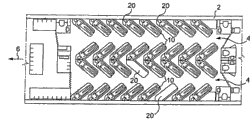
Fig. 1-3 illustrate the birds-eye view of arranging according to aircraft cabin of the present invention.
The aircraft cabin here has two sidewalls 2 and two vertical passages 4 in a conventional manner.Also can see some legacy equipments of aircraft cabin on these figure, be not described in detail here.These equipment comprise sanitary accomodation, waggon take between and other cloak-room.Arrow 6 in figure illustrates the heading of aircraft.
In a conventional manner, between each sidewall 2 and a vertical passage 4, be provided with on the other hand the passenger's who is seated for receiving seat 8 between two vertical passages 4 on the one hand.Here, the location at seat 8 is unique fully.
The conventional in layout lined up rows and columns as seat, the seat is here arranged one by one.But the row 10 here is not vertical with vertical passage 4, but tilt with respect to this passage.The inclination of row 10 makes to be sitting in passenger on seat 8 on the one hand substantially towards the place ahead of aircraft, makes on the other hand these passengers also towards vertical passage 4.It may be noted that a vertical passage 4 leads to every a line 10 seats 8.Like this, the seat 8 of a line 10 is towards the vertical passage 4 that leads to described row 10.
In this layout, for the row 10 along sidewall 2, the seat 8 of the most close respective side walls 2 is more forward than the seat 8 farther from respective side walls 2.
Fig. 2 illustrates the aircraft cabin identical with Fig. 1.But location and the Fig. 1 of the handrail 16 shown in this figure are slightly different, therefore three passengers can be received in every a line 10 seats 8.Handrail 16 can be the movable hand rail of seat 8 transverse translations relatively.But in a preferred embodiment, every a line 10 seats 8 are provided with two cover handrails 16: first set handrail 16 is received two passengers for row 10 is configured to, and the second cover handrail 16 is received three passengers for row 10 is configured to.Two handrails 16 at row 10 two ends are that two cover handrails share.Therefore always have six handrails.Each handrail pivotable is installed, in order to can fold in backrest 14.Therefore handrail can cover and the similar fabric of corresponding backrest 14, when handrail, does not almost see during in folding elevated position.When row 10 will be received two passengers, be arranged to the seat space of two large width, each seat space has two oneself handrails 16.In the layout of the row 10 for three passengers, use four in six handrails, but, here for each position, adjacent position shares a handrail 16.
In Fig. 2, can see, there is an additional seat 18 at each lambdoid tip formed by two row 10 seats 8.This seat along heading towards the aircraft front portion.Therefore, the layout shown in Fig. 2 can make 13 passengers travel side by side.
Therefore in the layout proposed, two one group or ternary and arrange seats are arranged here, do not stagger.The direction at seat is vertical with the direction of the row at their places.Every side at a vertical passage has the seat be parallel to each other capable.With conventional in layout, compare, its unique distinction is, seat is capable not vertical with the vertical passage that leads to these row, but tilt.This inclination makes the passenger who is sitting on these seats towards the passage that can lead to described seat.The layout of this complete uniqueness has many advantages.At first, for given space, it can receive a lot of passengers.Comparison diagram 1,2 can also find, this layout is adjustable.
Another advantage of this layout is, most of passenger can leave their seat and the adjacent seat that needn't hinder them.In the embodiment of Fig. 2, only have along passenger or the passenger on the lambdoid most advanced and sophisticated side formed by two row 10 of sidewall 2 and need apologize to their adjacent seat when their seat is left in hope.But these seats are still attractive, because the passenger in these positions compares and can obtain additional space with other passengers.Also it may be noted that the inclination by the relative vertical passage of this row, passenger's shank can obtain larger space.
In seat according to the present invention layout, three principal parameters work.At first be the width of passenger cabin, this width generally depends on the diameter that is generally columniform aircraft fuselage.Then be the spacing between two row seats.In traditional aircraft cabin, this spacing is between the 28-34 inch, between 0.71-0.86 rice.Row is the 3rd principal parameter with respect to the leaning angle of corresponding vertical passage.The selection of this angle preferably makes, according to the spacing between two row seats especially, also according to the width of passenger cabin, the passenger adjacent with the passenger of the other capable end of vertical passage can leave (and arrival) his seat, and can not bother, is not positioned at the adjacent seat that row holds and need apologizes to it.
In the embodiment of Fig. 2, at each lambdoid most advanced and sophisticated place, be provided with a seat 18.But also can consider other layout here.For example, this position also can be used for receiving luggage.Also can this position be set to overcoat for receiving the passenger and the built-in wardrobe of overcoat.Also can be set to bar desk.
Another advantage of this layout is the service during convenient flight.The crew can more easily touch the passenger, in order to provide catering service for the passenger.In addition, when take-off and landing, the crew more easily checks safety strap.
As shown in Figure 3, Fig. 1,2 layout can also be received the passenger in the state of couching.As shown in Figure 8,9, be set to each every row 10 here and receive the passenger of two positions that couch.Therefore, all passengers that are seated as shown in Figure 1 travelling also can be in the position that couches in passenger cabin.In order to make these passengers cosily in the position that couches, utilize the width at the seat 8 that forms row 10, and utilize the space of every row 10 ends.For the row 10 be positioned near sidewall 2, utilize here in sidewall 2 and the space between the seat 8 of close this sidewall.The utilization in this space can significantly increase passenger's the length that couches.For the row of the centre between vertical passage 4, utilize the part at seat 18 to form sleeping berth in each corresponding lambdoid row.
In one is implemented modification, three stacked sleeping berths can be set, rather than two.Therefore can provide for all passengers the position of sleep, even while in a line seat, three passengers being arranged.
How the row 10 that Fig. 8,9 illustrates seat 8 is converted to sleeping berth.File FR2753170 shows the utilizable seat that can be exchanged into sleeping berth here.
In an illustrated embodiment, it may be noted that in order from seat, to be transitioned into clinostatism, backrest 14 can approximately 90 ° of pivotables (be slightly less than 90 °, because backrest is not generally vertical, but tilt a little).The seat surface 12 that it may be noted that each seat consists of two parts, part 12a and a pivoting portions 12b who connects together with backrest 14.The edge of the upper sleeping berth that therefore part 12a pivotable together with backrest 14, and formation forms like this.Approximately 180 ° of the front edge pivotables of the relative seat surface of part 12b of seat surface, to form the surface that couches of lower sleeper.Therefore form the wider sleeping berth of the degree of depth of the seat surface 12 when being seated.
Fig. 5 illustrates two kinds of possible layouts in the single channel aircraft.This illustrates, and receives six side by side in passenger's single channel aircraft for example being traditionally arranged to be, and can increase the width of passage, retains six seats side by side simultaneously, or is transitioned into eight and arrange seatses.In this layout, with have six side by side the conventional in layout of passenger's lateral rows compare, passenger's comfort level improves.This layout makes passenger's leg that larger space be arranged.In sidewall one side, the passenger also has place, and does not lean sidewall.Only also it may be noted that the passenger (side by side six passengers) other in sidewall need to apologize to adjacent seat while leaving his position.Two passengers of other of this row can leave their position, and without apologizing.
Fig. 6 illustrates another layout, with the layout of Fig. 1-3, compares, and this layout has two vertical passages.Here, nine passengers travelling of can sitting in a line, and six can be side by side with the position travelling that couches.Here, the row 10 at one group of seat 8 is arranged along each sidewall of aircraft, the row 10 at one group of seat be parallel to each other 8 is arranged between two vertical passages 4.These row between vertical passage are basic identical with the row 10 along the seat 8 of sidewall 2.The row 10 at all these seats 8 can be converted to sleeping berth.When the passenger is seated, as shown in Figure 5,6, can notice the 20,Gai space, space of every row end or in sidewall 2 one sides at every turn, or in vertical passage 4 one sides.The space be substantially triangular in shape in this birds-eye view can be used as storage and receives space, the mat and/or the quilt that use when at seat, being converted to sleeping berth.
Fig. 4 illustrates another enforcement modification of two layouts between vertical passage.Here seat is capable no longer forms chevron pointing, but staggers in relatively lambdoid position.Can obtain more spaces in the situation that the distance between two vertical passages is limited like this.This Fig. 4 also illustrates the possibility (also can adopt in other embodiments of the invention) that 10 the back side of being expert at arranges foldable base 22.After this foldable base preferably is arranged in the seat 8 of the most close vertical passage that leads to described row of this row.Use this foldable base can make two people's basic side opposites, this talk of being more convenient for.
Fig. 7 illustrates another enforcement modification that passenger cabin shown in Fig. 1-3 is arranged.Here, to every a line 10 at seat 8, the other seat of the passage 4 in row end preferably no longer aligns with the complete row in other seat of this row 10, but tilts towards other seat 8 of the row 10 of its end, place.This degree of dip is selected according to the width of arranged passenger cabin and the passage width of hope.This degree of dip is corresponding to the axis at the inclination seat of row end and, with the angle A between the axis at another seat of a line, this angle for example is less than 45 °, and preferably is less than 30 °.The angle A that Fig. 7 illustrates the axis at the axis at an inclination seat, the seat adjacent with this inclination seat and adopts here.
The inclination of this row end can acquire benefit on passage width.In addition, after the passenger is in place, the passenger's of the row end in passage one side leg is the Shi,Bi seat, seat that tilts to other seat at seat when capable other seat aligns, and in described passage, extends less.
When the row 10 at seat 8 according to the present invention, as shown in Fig. 6 example between two passages the time, above-mentioned seat tilts and preferably only forms in the end of described row 10.In this Fig. 6, it may be noted that in this layout, one of seat of row end is towards passage 4, and another seat back of the body of row end is towards passage.In the situation that this figure, previously described inclination relates to and is positioned at the row end and towards the seat of respective channel.
Fig. 7 is only shown with the row at three seats, and one of them seat tilts with respect to other two seats of this row, and this is to arrange for given passenger cabin.But the inclination at this row end seat can relate to seating capacity, and to be different from 3 seat capable.It is also arranged applicable to other of passenger cabin, for example not exclusively for the layout shown in Fig. 4-6.
Finally, how Fig. 9 can arrange trapped orbit 24 on passenger cabin ground 26 if illustrating, in order to the row 10 at seat 8 is fixed on passenger cabin ground, to implement the present invention.
As indicated in top description, as implied abovely make the seat line tilt can obtain many advantages in vertical passage.Generally, this layout can increase the ridership of the travelling that is seated in given space, also can increase in the same space the ridership of the travelling that couches simultaneously.The layout at seat is also favourable, because passenger seldom need to apologize to their adjacent seat when their seat is left in hope.
The layout proposed is all favourable for the controllability in space, passenger's traveling comfort and the movement in passenger cabin.For rear, this layout can reduce boards and time of lower machine.Still as noted above, the layout of proposition has also facilitated in-fight service.
Certainly, the invention is not restricted to the top preferred embodiment of describing as non-limiting example.Enforcement modification that do not illustrate above the invention still further relates to, those skilled in the art's within the reach.
Claims (20)
1. the passenger cabin of the vehicle of passenger-carrying, this passenger cabin has at least one vertical passage (4) and, for the seat (8) of receiving the passenger and embark on journey (10) arrange, each row can be led to by a vertical passage (4);
Wherein, at least one has the row (10) of at least two seats (8) to be in tilted layout with respect to a vertical passage (4), and the seat (8) of described at least one row (10) is arranged side by side, and direction is vertical with described at least one row (10), and towards the passage (4) that can lead to described at least one row (10), and, two row (10) seats (8) a line forms chevron pointing by another row, and seat or storage are received space and be located at lambdoid most advanced and sophisticated the locating formed by two row seats.
2. passenger cabin as claimed in claim 1, is characterized in that, two or three seats of a line are arranged side by side, and do not stagger.
3. passenger cabin as claimed in claim 1, it is characterized in that, the leaning angle of row (10) make be sitting in the seat (8) of row (10) institute towards the passenger at adjacent seat (8), the seat (8) of row (10) end of passage (4) one sides can leave his position, and leave the passenger on the seat (8) that is positioned at capable (10) end alone.
4. passenger cabin as described as one of claims 1 to 3, is characterized in that, two row (10) seats (8) a line, by another row, still vertically staggers.
5. passenger cabin as claimed in claim 1, is characterized in that, at least three passengers that are seated can be received in every row (10) seat (8).
6. passenger cabin as claimed in claim 5, is characterized in that, for a line at least, the seat of row end and passage one side is towards other seat inclination of this row.
7. passenger cabin as claimed in claim 1, it is characterized in that, at least a line (10) seat (8) can be converted to two stacked sleeping berths, each seat (8) has seat surface (12) and backrest (14), and backrest (14) can pivotable, in order to be converted to the plane surface that forms a basic horizontal on the seat surface of sleeping berth (12).
8. passenger cabin as claimed in claim 1, is characterized in that, at least one row (10) is adjustable, in order to can receive two or three passengers that are seated.
9. passenger cabin as claimed in claim 1, is characterized in that, it has two sidewalls (2) and a vertical passage (4), and the row of some inclinations is arranged between a sidewall (2) and vertical passage (4) in parallel to each other.
10. passenger cabin as claimed in claim 1, it is characterized in that, it has two sidewalls (2) and two vertical passages (4), the row of some inclinations (10) is arranged between a vertical passage (4) and a sidewall (2) in parallel to each other, and the row of some inclinations (10) is arranged between two vertical passages (4) in parallel to each other.
11. passenger cabin as claimed in claim 1, it is characterized in that, it has two sidewalls (2) and two vertical passages (4), the row of some inclinations (10) is arranged between a vertical passage (4) and a sidewall (2) in parallel to each other, and the row of some inclinations (10) becomes chevron pointing to be arranged between two vertical passages (4).
12. passenger cabin as described as one of claim 9 to 11, it is characterized in that, every row (10) seat (8) can be converted to two stacked sleeping berths, and the supplementary part that is used to form sleeping berth along each row (10) and the space be substantially triangular in shape (20) between respective side walls (2) of a sidewall (2).
13. passenger cabin as claimed in claim 1, is characterized in that, all seats (8) are all towards the front portion of the vehicle.
14. passenger cabin as claimed in claim 7, is characterized in that, at least the seat surface at a line seat is divided into two parts, and a part connects together with backrest, and pivoting portions is approximately 180 ° of the front edge pivotables of seat surface relatively, to form the surface that couches of lower sleeper.
15. the passenger cabin of the vehicle of passenger-carrying, this passenger cabin has at least one vertical passage (4) and, for the seat (8) of receiving the passenger and embark on journey (10) arrange, each row can be led to by a vertical passage (4);
Wherein, at least one has the row (10) of at least two seats (8) to be in tilted layout with respect to a vertical passage (4), and the seat (8) of described at least one row (10) is arranged side by side, and direction is vertical with described at least one row (10), and towards the passage (4) that can lead to described at least one row (10);
The leaning angle of row (10) make be sitting in the seat (8) of row (10) institute towards the passenger at adjacent seat (8), the seat (8) of row (10) end of passage (4) one sides can leave his position, and leave the passenger on the seat (8) that is positioned at capable (10) end alone;
At least three passengers that are seated can be received in every row (10) seat (8).
16. passenger cabin as claimed in claim 15, is characterized in that, two row (10) seats (8) a line forms chevron pointing by another row.
17. passenger cabin as claimed in claim 15, is characterized in that, a seat (18) is located at the lambdoid most advanced and sophisticated place formed by two row (10) seats (8).
18. passenger cabin as claimed in claim 15, is characterized in that, for a line at least, the seat of row end and passage one side is towards other seat inclination of this row.
19. passenger cabin as claimed in claim 15, it is characterized in that, at least a line (10) seat (8) can be converted to two stacked sleeping berths, each seat (8) has seat surface (12) and backrest (14), and backrest (14) can pivotable, in order to be converted to the plane surface that forms a basic horizontal on the seat surface of sleeping berth (12).
20. aircraft, is characterized in that, it has passenger cabin as described as one of claim 1 to 19.
Priority Applications (1)
| Application Number | Priority Date | Filing Date | Title |
|---|---|---|---|
| CN201310060688.8A CN103183127B (en) | 2007-12-06 | 2008-12-05 | The vehicle cabin of passenger-carrying and corresponding aircraft |
Applications Claiming Priority (5)
| Application Number | Priority Date | Filing Date | Title |
|---|---|---|---|
| FR0708523A FR2924683A1 (en) | 2007-12-06 | 2007-12-06 | Cabin for e.g. double-aisle aircraft, has passenger seats arranged in rows that are inclined with respect to longitudinal aisles, where seats of each row are arranged side by side and oriented perpendicular to row and towards aisles |
| FR0708523 | 2007-12-06 | ||
| FR0800263 | 2008-01-18 | ||
| FR0800263A FR2924682B1 (en) | 2007-12-06 | 2008-01-18 | OPTIMIZED PLACEMENT OF AN AIRCRAFT CABIN |
| PCT/FR2008/001697 WO2009101294A2 (en) | 2007-12-06 | 2008-12-05 | Optimised aircraft cabin layout |
Related Child Applications (1)
| Application Number | Title | Priority Date | Filing Date |
|---|---|---|---|
| CN201310060688.8A Division CN103183127B (en) | 2007-12-06 | 2008-12-05 | The vehicle cabin of passenger-carrying and corresponding aircraft |
Publications (2)
| Publication Number | Publication Date |
|---|---|
| CN101925514A CN101925514A (en) | 2010-12-22 |
| CN101925514B true CN101925514B (en) | 2013-12-25 |
Family
ID=39538776
Family Applications (2)
| Application Number | Title | Priority Date | Filing Date |
|---|---|---|---|
| CN201310060688.8A Active CN103183127B (en) | 2007-12-06 | 2008-12-05 | The vehicle cabin of passenger-carrying and corresponding aircraft |
| CN200880125284XA Active CN101925514B (en) | 2007-12-06 | 2008-12-05 | Optimised aircraft cabin layout |
Family Applications Before (1)
| Application Number | Title | Priority Date | Filing Date |
|---|---|---|---|
| CN201310060688.8A Active CN103183127B (en) | 2007-12-06 | 2008-12-05 | The vehicle cabin of passenger-carrying and corresponding aircraft |
Country Status (10)
| Country | Link |
|---|---|
| US (1) | US9162766B2 (en) |
| EP (1) | EP2219945B1 (en) |
| JP (1) | JP5580209B2 (en) |
| CN (2) | CN103183127B (en) |
| BR (1) | BRPI0818973B1 (en) |
| CA (1) | CA2707670C (en) |
| ES (1) | ES2414061T3 (en) |
| FR (2) | FR2924683A1 (en) |
| RU (1) | RU2517624C2 (en) |
| WO (1) | WO2009101294A2 (en) |
Families Citing this family (28)
| Publication number | Priority date | Publication date | Assignee | Title |
|---|---|---|---|---|
| GB0903744D0 (en) | 2009-03-04 | 2009-04-15 | Virgin Atlantic Airways Ltd | A seating insallation for a passenger vehicle |
| GB2469180B8 (en) * | 2009-03-23 | 2016-06-08 | Air New Zealand Ltd | Vehicle seating arrangement |
| FR2975952B1 (en) * | 2011-06-01 | 2013-07-19 | Eads Sogerma | CONVERTIBLE SEAT IN SLEEVE |
| US8944379B2 (en) | 2011-10-28 | 2015-02-03 | Zodiac Seat Shells Us Llc | Aircraft seating configuration |
| JP6102910B2 (en) * | 2012-02-23 | 2017-03-29 | 横浜ゴム株式会社 | Installation method of aircraft restroom unit and aircraft |
| GB201217319D0 (en) * | 2012-09-27 | 2012-11-14 | Acumen Design Associates Ltd | Aircraft passenger seating arrangement |
| US9889936B2 (en) * | 2012-10-30 | 2018-02-13 | The Boeing Company | Curved seating layout |
| JP5565782B1 (en) * | 2013-04-04 | 2014-08-06 | 光雄 福谷 | Passage device for chair seat room with vehicle entrance / exit |
| EP2923946B1 (en) | 2014-03-28 | 2018-05-30 | Airbus Operations GmbH | Passenger seat arrangement for a vehicle |
| WO2015155751A1 (en) * | 2014-04-11 | 2015-10-15 | Zodiac Seats France | Seat unit with an advertising surface |
| EP2974961B1 (en) * | 2014-07-15 | 2017-04-26 | Airbus Defence and Space GmbH | Seat assembly, seat arrangement and passenger cabin for an aircraft |
| EP3204295B1 (en) * | 2014-10-07 | 2022-10-05 | Safran Seats GB Limited | Paired herringbone high density business class seating arrangement |
| CN104527685A (en) * | 2014-12-19 | 2015-04-22 | 文曙东 | Berth layout structure for passenger train sleeping berth compartment |
| CN104554315B (en) * | 2015-01-04 | 2017-05-31 | 文曙东 | Passenger vehicles Double-deck sleeping berth structure |
| US9708065B2 (en) * | 2015-04-07 | 2017-07-18 | The Boeing Company | Crown cabin configuration for an aircraft |
| WO2016164293A2 (en) | 2015-04-08 | 2016-10-13 | Zodiac Seat Shells U.S. Llc | Passenger accommodation systems including partition walls |
| DE102015105540A1 (en) * | 2015-04-10 | 2016-10-13 | Airbus Operations Gmbh | Space-optimized passenger seat arrangement for a vehicle cabin |
| EP3356229B1 (en) * | 2015-09-29 | 2021-05-19 | B/E Aerospace, Inc. | Airliner passenger suite seating arrangements with shared aisle suite access |
| WO2017067409A1 (en) * | 2015-10-20 | 2017-04-27 | Butterfly Flexible Seating Solutions Limited | Convertible seating unit and seating arrangement |
| CN105857616A (en) * | 2016-03-31 | 2016-08-17 | 陈刚 | Airliner flat-on economy cabin |
| EP3263444B1 (en) * | 2016-06-30 | 2020-04-01 | Cathay Pacific Airways Limited | Cabin module and layout for a passenger aircraft |
| EP3601050B1 (en) * | 2017-03-31 | 2021-01-27 | Safran Seats | Arrangement of individual seats for passengers of an aeroplane |
| WO2020091885A1 (en) * | 2018-10-29 | 2020-05-07 | Safran Cabin Inc. | Aircraft with selective cargo area access |
| USD948412S1 (en) | 2019-03-01 | 2022-04-12 | Werner Co. | Bulkhead for a vehicle |
| US11319072B2 (en) * | 2019-04-01 | 2022-05-03 | B/E Aerospace, Inc. | Business class travel suite arrangements for narrow body and wide body aircraft |
| WO2020223246A1 (en) * | 2019-04-29 | 2020-11-05 | Safran Cabin Inc. | Aircraft with separate zones |
| FR3105176B1 (en) * | 2019-12-20 | 2022-07-22 | Safran Seats | PASSENGER SEAT ARRANGEMENT |
| CN111859548A (en) * | 2020-07-28 | 2020-10-30 | 中国商用飞机有限责任公司 | Automatic layout method and system for airplane passenger cabin |
Citations (1)
| Publication number | Priority date | Publication date | Assignee | Title |
|---|---|---|---|---|
| US2414730A (en) * | 1943-07-27 | 1947-01-21 | Acf Brill Motors Company | Seating arrangement for passenger vehicles |
Family Cites Families (35)
| Publication number | Priority date | Publication date | Assignee | Title |
|---|---|---|---|---|
| US2046859A (en) * | 1935-05-27 | 1936-07-07 | Weiss George | Automobile bus |
| US2250193A (en) * | 1937-04-14 | 1941-07-22 | Boeing Aircraft Co | Convertible seat and berth arrangement |
| US2632408A (en) * | 1951-10-04 | 1953-03-24 | Giles Eugene Manning | Compartmentizable seat for railroad coaches and the like |
| GB733081A (en) * | 1952-08-21 | 1955-07-06 | West Yorkshire Road Car Compan | Improvements in seating arrangements for passenger carrying vehicles |
| US2947349A (en) * | 1958-04-10 | 1960-08-02 | Karl D Kryter | Seat and seating arrangement |
| US3608958A (en) * | 1969-08-04 | 1971-09-28 | La Z Boy Chair Co | Multiple seat unit of the reclining and rocking type |
| EP0126056B1 (en) * | 1983-05-16 | 1988-08-10 | S.A. Seatco N.V. | Seat assembly for an aircraft fuselage |
| US4555821A (en) * | 1984-04-30 | 1985-12-03 | Page Elwin H | Sofa-bunk bed combination |
| JPH0361486U (en) * | 1989-10-20 | 1991-06-17 | ||
| SU1736809A1 (en) | 1990-07-19 | 1992-05-30 | С.А.Габриел н | Body interior of transport vehicle |
| CN2140880Y (en) * | 1992-12-21 | 1993-08-25 | 于建康 | Seat specially adapted for civil passenger plane |
| FR2753170B1 (en) * | 1996-09-09 | 1998-11-27 | Aerospatiale | BED SEAT FOR AIRCRAFT |
| RU10655U1 (en) | 1998-11-20 | 1999-08-16 | Сидоров Михаил Евгеньевич | VEHICLE REST CORNER |
| US7070149B2 (en) * | 2000-09-19 | 2006-07-04 | Advanced Product Development, Llc | Seats that convert to sleeper bunks |
| DE10059603B4 (en) * | 2000-11-30 | 2006-06-01 | Airbus Deutschland Gmbh | Airplane passenger cabin with an arrangement of passenger seats |
| FR2818595B1 (en) * | 2000-12-26 | 2003-03-07 | Eads Sogerma | BED CONVERTIBLE ARMCHAIR, ESPECIALLY FOR AIRCRAFT |
| ATE309110T1 (en) | 2001-08-09 | 2005-11-15 | Virgin Atlantic Airways Ltd | A SEATING ARRANGEMENT AND A PASSENGER ACCOMMODATION UNIT FOR A VEHICLE |
| EP1314643B1 (en) * | 2001-11-27 | 2006-03-01 | Airbus Deutschland GmbH | Arrangement of passenger seats in transport vehicles, in particular in aircraft cabins |
| AU2002361243A1 (en) * | 2001-12-20 | 2003-07-09 | James Thompson | Seating for a vehicle |
| FR2839947B1 (en) | 2002-05-22 | 2004-11-26 | Airbus | INDIVIDUAL MODULE FOR AIRCRAFT PASSENGER |
| FR2843730B1 (en) * | 2002-08-23 | 2005-07-08 | Airbus | INTERIOR FITTING OF AN AIRCRAFT CABIN |
| US6793282B2 (en) * | 2002-09-10 | 2004-09-21 | B E Aerospace, Inc. | Convertible passenger seat assembly |
| JP2006513916A (en) * | 2003-03-18 | 2006-04-27 | ウェバー エアクラフト エルピー | Seat mounting system and method |
| GB0316733D0 (en) | 2003-07-17 | 2003-08-20 | Thompson James | Seating for a passenger vehicle |
| JP4175474B2 (en) | 2004-02-05 | 2008-11-05 | 三菱重工業株式会社 | Aircraft, moving body |
| US7320446B2 (en) | 2004-02-26 | 2008-01-22 | Airbus | Interior layout of an aircraft cabin |
| FR2866840B1 (en) * | 2004-02-26 | 2007-06-29 | Airbus | INTERIOR AIRCRAFT CABIN ARRANGEMENT |
| GB0419148D0 (en) * | 2004-08-27 | 2004-09-29 | Britax Aircraft Interiors Uk L | Aircraft seat |
| US7188806B2 (en) * | 2004-10-22 | 2007-03-13 | B E Aerospace, Inc. | Aircraft passenger accommodation unit with deployable bed |
| US7712704B2 (en) | 2005-06-07 | 2010-05-11 | Airbus | Arrangement of seats and baggage compartments in an aircraft cabin |
| US7721990B2 (en) * | 2005-07-29 | 2010-05-25 | Airbus Deutschland Gmbh | Passenger compartment |
| GB2438162A (en) * | 2006-05-19 | 2007-11-21 | British Airways Plc | Reclining aircraft seat convertible into bed |
| US20090146004A1 (en) * | 2007-12-06 | 2009-06-11 | B E Aerospace, Inc. | Aircraft seating arrangement and seat |
| US8196864B2 (en) * | 2008-09-05 | 2012-06-12 | Weber Aircraft Llc | Seating arrangements particularly for passenger aircraft |
| USD649793S1 (en) * | 2009-12-10 | 2011-12-06 | Air New Zealand Limited | Aircraft seat |
-
2007
- 2007-12-06 FR FR0708523A patent/FR2924683A1/en active Pending
-
2008
- 2008-01-18 FR FR0800263A patent/FR2924682B1/en not_active Expired - Fee Related
- 2008-12-05 EP EP08872447A patent/EP2219945B1/en active Active
- 2008-12-05 JP JP2010536505A patent/JP5580209B2/en active Active
- 2008-12-05 CN CN201310060688.8A patent/CN103183127B/en active Active
- 2008-12-05 US US12/746,423 patent/US9162766B2/en active Active
- 2008-12-05 RU RU2010127852/11A patent/RU2517624C2/en not_active IP Right Cessation
- 2008-12-05 ES ES08872447T patent/ES2414061T3/en active Active
- 2008-12-05 WO PCT/FR2008/001697 patent/WO2009101294A2/en active Application Filing
- 2008-12-05 CA CA2707670A patent/CA2707670C/en not_active Expired - Fee Related
- 2008-12-05 BR BRPI0818973A patent/BRPI0818973B1/en not_active IP Right Cessation
- 2008-12-05 CN CN200880125284XA patent/CN101925514B/en active Active
Patent Citations (1)
| Publication number | Priority date | Publication date | Assignee | Title |
|---|---|---|---|---|
| US2414730A (en) * | 1943-07-27 | 1947-01-21 | Acf Brill Motors Company | Seating arrangement for passenger vehicles |
Also Published As
| Publication number | Publication date |
|---|---|
| CN103183127B (en) | 2016-03-30 |
| EP2219945A2 (en) | 2010-08-25 |
| CA2707670C (en) | 2016-02-09 |
| EP2219945B1 (en) | 2013-03-20 |
| US20110101161A1 (en) | 2011-05-05 |
| JP5580209B2 (en) | 2014-08-27 |
| FR2924682B1 (en) | 2010-08-27 |
| BRPI0818973B1 (en) | 2019-09-10 |
| RU2517624C2 (en) | 2014-05-27 |
| FR2924683A1 (en) | 2009-06-12 |
| WO2009101294A2 (en) | 2009-08-20 |
| RU2010127852A (en) | 2012-01-20 |
| US9162766B2 (en) | 2015-10-20 |
| BRPI0818973A2 (en) | 2015-05-05 |
| WO2009101294A3 (en) | 2009-10-08 |
| FR2924682A1 (en) | 2009-06-12 |
| ES2414061T3 (en) | 2013-07-18 |
| CA2707670A1 (en) | 2009-08-20 |
| CN101925514A (en) | 2010-12-22 |
| JP2011506161A (en) | 2011-03-03 |
| CN103183127A (en) | 2013-07-03 |
Similar Documents
| Publication | Publication Date | Title |
|---|---|---|
| CN101925514B (en) | Optimised aircraft cabin layout | |
| US9919800B2 (en) | Bed extension | |
| US8882036B2 (en) | Aircraft seating arrangement | |
| EP2217496B1 (en) | Aircraft seating arrangement | |
| CN102849212B (en) | Can be transformed into the seat tool of sleeping berth | |
| US9545999B2 (en) | Seating arrangement | |
| US9527592B2 (en) | High end business class cabin arrangement | |
| US20170327232A1 (en) | Aircraft passenger seat with enhanced lie flat position spacing | |
| US20170129611A1 (en) | Aircraft seating arrangement with enhanced lay flat position spacing | |
| US11319072B2 (en) | Business class travel suite arrangements for narrow body and wide body aircraft | |
| CN104071338A (en) | Arrangement of seats convertible into bunks | |
| US11180254B2 (en) | Space-efficient flat-bed seating arrangement | |
| US11905019B2 (en) | Passenger cabin area and aircraft having a passenger cabin area | |
| CN107697305A (en) | A kind of sleeping berth and seat mixed cabin of long-range jumbo jet | |
| CN105857616A (en) | Airliner flat-on economy cabin | |
| CN1922074B (en) | Interior layout of an aircraft cabin | |
| CN205440883U (en) | Passenger plane tie economy class of lying | |
| CN113581234A (en) | High-density seat layout structure of passenger transport vehicle |
Legal Events
| Date | Code | Title | Description |
|---|---|---|---|
| C06 | Publication | ||
| PB01 | Publication | ||
| C10 | Entry into substantive examination | ||
| SE01 | Entry into force of request for substantive examination | ||
| C14 | Grant of patent or utility model | ||
| GR01 | Patent grant |