CN101891116A - Split rotating shaft joint - Google Patents

Split rotating shaft joint Download PDF

Info

Publication number
CN101891116A
CN101891116A CN 201010256401 CN201010256401A CN101891116A CN 101891116 A CN101891116 A CN 101891116A CN 201010256401 CN201010256401 CN 201010256401 CN 201010256401 A CN201010256401 A CN 201010256401A CN 101891116 A CN101891116 A CN 101891116A
Authority
CN
China
Prior art keywords
rotating shaft
axis
shaft joint
rear axle
split type
Prior art date
Legal status (The legal status is an assumption and is not a legal conclusion. Google has not performed a legal analysis and makes no representation as to the accuracy of the status listed.)
Pending
Application number
CN 201010256401
Other languages
Chinese (zh)
Inventor
林张荣
黄延涛
向兵
徐君
于杰
Current Assignee (The listed assignees may be inaccurate. Google has not performed a legal analysis and makes no representation or warranty as to the accuracy of the list.)
Lonking (Shanghai) Hydraulic Co.,Ltd.
Original Assignee
HERKULES (SHANGHAI) HYDRAULIC MACHINERY CO Ltd
Priority date (The priority date is an assumption and is not a legal conclusion. Google has not performed a legal analysis and makes no representation as to the accuracy of the date listed.)
Filing date
Publication date
Application filed by HERKULES (SHANGHAI) HYDRAULIC MACHINERY CO Ltd filed Critical HERKULES (SHANGHAI) HYDRAULIC MACHINERY CO Ltd
Priority to CN 201010256401 priority Critical patent/CN101891116A/en
Publication of CN101891116A publication Critical patent/CN101891116A/en
Pending legal-status Critical Current

Links

Images

Landscapes

  • Pivots And Pivotal Connections (AREA)

Abstract

The invention relates to a split rotating shaft joint, which is characterized by comprising a front shaft, a middle shaft, a rear shaft, a middle sleeve, an oil distribution sleeve and a water distribution sleeve which are split, wherein after assembly, the middle shaft is positioned between the front shaft and the rear shaft; the middle sleeve is sleeved outside the middle shaft; and the oil distribution sleeve and the water distribution sleeve are sleeved outside the rear shaft. The split rotating shaft joint has the advantages of simplified processing technology, high measurement operability, good size precision, and better coaxiality after the assembly compared with an integral structure by adopting a split structure.

Description

A kind of split type rotating shaft joint
Technical field
The present invention relates to a kind of rotating shaft joint, in engineering machinery field, be used for the hydraulic oil and the electric system of getting off are transported to the actuating unit of getting on the bus.
Background technology
Rotating shaft joint is applied on the construction machinery and equipments such as hoisting crane, excavating machine, and it is the device that a kind of handle hydraulic oil of getting off and electric system are transported to the actuating unit of getting on the bus.Rotating shaft joint commonly used is an one-piece construction, is made up of main shaft and main body two parts.Main body is made of rotor, stator and sealing member again.Rotor is fixed on the turn table, follow the turn table revolution, stator is fixed on the chassis motionless, is provided with the oil circuit that is connected by annular oil groove between rotor and the stator, by the rotation change of rotor and the angle between the stator hydraulic fluid port, thus the output port of change hydraulic oil.
In the past, the complete dependence on import of rotating shaft joint, its price is expensive unusually, has increased the productive costs of enterprise.After treating the rotating shaft joint production domesticization, face a new difficult problem again.Because rotating shaft joint commonly used is an one-piece construction, so main shaft and main body are long usually, and the processing comparison difficulty of getting up is difficult to guarantee right alignment.And seal groove on the main body and distribution channel are processed the bad detection in back because the hole is deep, add the restriction of processing technology, and whole assembling back result of use is not good.
Summary of the invention
The purpose of this invention is to provide and a kind ofly not only process easy but also can guarantee the rotating shaft joint of right alignment.
In order to achieve the above object, technical scheme of the present invention has provided a kind of split type rotating shaft joint, it is characterized in that, comprise split front axle, axis, rear axle, middle cover, join oil jacket and water distribution cover, after the assembling, axis has middle cover at middle outer shaft sleeve between front axle and rear axle, outer shaft sleeve has the oil jacket of joining and water distribution cover in the back.
Further, seal by native sand between described axis and the described middle cover, described joining between oil jacket and described water distribution cover and the described rear axle seals with seal ring by O shape combination rotating seal ring and piston rod respectively, seals by O-ring seals between described axis and the described rear axle.
Outer shaft sleeve has big flange in described, and big flange is arranged in the side of cover, seals by O-ring seals between big flange and the middle cover.
On described inwall of joining oil jacket and water distribution cover, be embedded with guide ring respectively.
On the rear end of described rear axle, be provided with bonnet.
Described front axle comprises the axis body that has through hole, is provided with flange in the rear end of axis body, is embedded with O-ring seals on the inwall of through hole front end.
Described rear axle comprises the adapter shaft that has through hole, is provided with butt flange on the front end of adapter shaft, and baffle plate is located on the adapter shaft, and baffle plate is positioned at the rear of butt flange.
The present invention carries out according to the principle of work of rotating shaft joint, utilizes mandrel to be connected multiple fluid pressure mediums such as also can carrying Oil, Water, Gas continuously with the relative motion interrupted, rotation continuously of overcoat; Meanwhile, change traditional one-piece construction into split-type structural, guaranteed the rotating property of mandrel and overcoat better.
Advantage of the present invention is: after adopting split-type structural, simplified processing technology is measured workablely, and dimensional accuracy is relatively good, obviously is better than one-piece construction.
Description of drawings
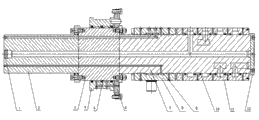
Fig. 1 is a kind of split type rotating shaft joint scheme drawing provided by the invention;
Fig. 2 is the front axle scheme drawing;
Fig. 3 is the rear axle scheme drawing.
The specific embodiment
Below in conjunction with embodiment the present invention is described.
Embodiment
As shown in Figure 1, be a kind of split type rotating shaft joint provided by the invention, comprise split front axle 2, axis 3, rear axle 7, middle cover 4, join oil jacket 8 and water distribution cover 11, after the assembling, axis 3 is provided with bonnet 12 on the rear end of rear axle 7 between front axle 2 and rear axle 7, cover 4 in being with outside axis 3, outside rear axle 7, be with and join oil jacket 8 and water distribution cover 11, on the inwall of joining oil jacket 8 and water distribution cover 11, be embedded with guide ring respectively.Be with big flange 6 outside axis 3, big flange 6 is arranged in the side of cover 4, seals by O-ring seals between big flange 6 and the middle cover 4.
Pass through native sand 5 sealings between axis 3 and the described middle cover 4, join and pass through O shape combination rotating seal ring 9 and piston rod seal ring 10 sealings between oil jacket 8 and water distribution cover 11 and the described rear axle 7 respectively, seal by O-ring seals between axis 3 and the rear axle 7.
As shown in Figure 2, front axle 2 comprises the axis body 13 that has through hole, is provided with flange 14 in the rear end of axis body 13, is embedded with O-ring seals 1 on the inwall of through hole front end.
As shown in Figure 3, rear axle 7 comprises the adapter shaft 17 that has through hole, is provided with butt flange 15 on the front end of adapter shaft 17, and baffle plate 16 is located on the adapter shaft 17, and baffle plate 16 is positioned at the rear of butt flange 15.
During deep hole working, earlier with the positioning spigot of front axle 2 upper flanges 14 and an end fit on of axis 3, subsequently with the positioning spigot of butt flange 15 on the rear axle 7 and the other end fit on of axis 3, connect fastening with tie bolt then, deep hole processing, treat that deep hole working is over, with front axle 2, axis 3, rear axle 7 separately, difference processing oil oral pore, seal with O ring groove.
During assembling, front axle 2, axis 3, the rear axle 7 usefulness tie bolts that process are connected fastening back as mandrel, then at middle cover 4, join in oil jacket 8, the water distribution cover 11 seal ring be installed respectively, with assemble sealing member middle cover 4, join oil jacket 8, water distribution is overlapped 11 once mounting on mandrel, by connecting fastener locking.
In cover 4, join the processing of seal groove on oil jacket 8, the water distribution cover 11 and oil groove, tank owing to be split type, single-piece length is all shorter, processing is got up than being easier to, and groove width, groove depth can measure, and is convenient to dimensional accuracy control.
Claims (7)

1. split type rotating shaft joint, it is characterized in that, comprise split front axle (2), axis (3), rear axle (7), middle cover (4), join oil jacket (8) and water distribution cover (11), after the assembling, axis (3) is positioned between front axle (2) and the rear axle (7), outside axis (3), be with middle cover (4), outside rear axle (7), be with and join oil jacket (8) and water distribution cover (11).
2. a kind of split type rotating shaft joint as claimed in claim 1, it is characterized in that, seal by native sand (5) between described axis (3) and the described middle cover (4), described joining between oil jacket (8) and described water distribution cover (11) and the described rear axle (7) seals with seal ring (10) by O shape combination rotating seal ring (9) and piston rod respectively, seals by O-ring seals between described axis (3) and the described rear axle (7).
3. a kind of split type rotating shaft joint as claimed in claim 1, it is characterized in that, be with big flange (6) outside described axis (3), big flange (6) is arranged in the side of cover (4), seals by O-ring seals between big flange (6) and the middle cover (4).
4. a kind of split type rotating shaft joint as claimed in claim 1 is characterized in that, is embedded with guide ring respectively on described inwall of joining oil jacket (8) and water distribution cover (11).
5. a kind of split type rotating shaft joint as claimed in claim 1 is characterized in that, is provided with bonnet (12) on the rear end of described rear axle (7).
6. a kind of split type rotating shaft joint as claimed in claim 1, it is characterized in that, described front axle (2) comprises the axis body (13) that has through hole, is provided with flange (14) in the rear end of axis body (13), is embedded with O-ring seals (1) on the inwall of through hole front end.
7. a kind of split type rotating shaft joint as claimed in claim 1, it is characterized in that, described rear axle (7) comprises the adapter shaft (17) that has through hole, on the front end of adapter shaft (17), be provided with butt flange (15), baffle plate (16) is located on the adapter shaft (17), and baffle plate (16) is positioned at the rear of butt flange (15).
CN 201010256401 2010-08-18 2010-08-18 Split rotating shaft joint Pending CN101891116A (en)

Priority Applications (1)

Application Number Priority Date Filing Date Title
CN 201010256401 CN101891116A (en) 2010-08-18 2010-08-18 Split rotating shaft joint

Applications Claiming Priority (1)

Application Number Priority Date Filing Date Title
CN 201010256401 CN101891116A (en) 2010-08-18 2010-08-18 Split rotating shaft joint

Publications (1)

Publication Number Publication Date
CN101891116A true CN101891116A (en) 2010-11-24

Family

ID=43100495

Family Applications (1)

Application Number Title Priority Date Filing Date
CN 201010256401 Pending CN101891116A (en) 2010-08-18 2010-08-18 Split rotating shaft joint

Country Status (1)

Country Link
CN (1) CN101891116A (en)

Cited By (4)

* Cited by examiner, † Cited by third party
Publication number Priority date Publication date Assignee Title
CN102705292A (en) * 2012-05-29 2012-10-03 徐州天龙液压机械有限公司 Hydraulic oil cylinder with novel connector body
CN103292102A (en) * 2013-06-25 2013-09-11 徐州重型机械有限公司 Wheel type crane and centre revolving joint thereof
CN110005887A (en) * 2019-04-30 2019-07-12 鞍山市昱虎流体设备有限公司 Dismountable Anti-freezing cryogen rotary joint
CN111362139A (en) * 2013-10-04 2020-07-03 宾纳快速升降系统公司 Rotary joint

Citations (8)

* Cited by examiner, † Cited by third party
Publication number Priority date Publication date Assignee Title
US20050046181A1 (en) * 2003-08-28 2005-03-03 Falconer Darcy Raymond Fluid rotary union
KR20050069735A (en) * 2003-12-31 2005-07-05 두산디앤디 주식회사 Multiple fluid supply apparatus for carrier of semiconductor wafer polishing system
CN101210632A (en) * 2006-12-28 2008-07-02 徐学新 Gyration type hydraulic operated valve
CN101216135A (en) * 2008-01-14 2008-07-09 江阴市长龄机械制造有限公司 Multi-oil path large-sized machinery hydraulic central swivel joint
CN201133532Y (en) * 2007-11-29 2008-10-15 湖北三江航天万山特种车辆有限公司 Multichannel heavy pressure swiveling joint
CN101684876A (en) * 2009-06-03 2010-03-31 无锡瑞佳精机有限公司 Improved hydraulic rotary joint
CN101780891A (en) * 2009-11-12 2010-07-21 无锡五冶金属压延有限公司 Expansion and reduction rotary joint device of a steel belt hydraulic coiler
CN201729584U (en) * 2010-08-18 2011-02-02 海克力斯(上海)液压机械有限公司 Split joint of rotating shaft

Patent Citations (8)

* Cited by examiner, † Cited by third party
Publication number Priority date Publication date Assignee Title
US20050046181A1 (en) * 2003-08-28 2005-03-03 Falconer Darcy Raymond Fluid rotary union
KR20050069735A (en) * 2003-12-31 2005-07-05 두산디앤디 주식회사 Multiple fluid supply apparatus for carrier of semiconductor wafer polishing system
CN101210632A (en) * 2006-12-28 2008-07-02 徐学新 Gyration type hydraulic operated valve
CN201133532Y (en) * 2007-11-29 2008-10-15 湖北三江航天万山特种车辆有限公司 Multichannel heavy pressure swiveling joint
CN101216135A (en) * 2008-01-14 2008-07-09 江阴市长龄机械制造有限公司 Multi-oil path large-sized machinery hydraulic central swivel joint
CN101684876A (en) * 2009-06-03 2010-03-31 无锡瑞佳精机有限公司 Improved hydraulic rotary joint
CN101780891A (en) * 2009-11-12 2010-07-21 无锡五冶金属压延有限公司 Expansion and reduction rotary joint device of a steel belt hydraulic coiler
CN201729584U (en) * 2010-08-18 2011-02-02 海克力斯(上海)液压机械有限公司 Split joint of rotating shaft

Cited By (6)

* Cited by examiner, † Cited by third party
Publication number Priority date Publication date Assignee Title
CN102705292A (en) * 2012-05-29 2012-10-03 徐州天龙液压机械有限公司 Hydraulic oil cylinder with novel connector body
CN103292102A (en) * 2013-06-25 2013-09-11 徐州重型机械有限公司 Wheel type crane and centre revolving joint thereof
CN111362139A (en) * 2013-10-04 2020-07-03 宾纳快速升降系统公司 Rotary joint
CN111362139B (en) * 2013-10-04 2021-03-30 宾纳快速升降系统公司 Rotary joint
CN110005887A (en) * 2019-04-30 2019-07-12 鞍山市昱虎流体设备有限公司 Dismountable Anti-freezing cryogen rotary joint
CN110005887B (en) * 2019-04-30 2024-03-12 鞍山市昱虎流体设备有限公司 Detachable anti-freezing low-temperature fluid rotary joint

Similar Documents

Publication Publication Date Title
CN201729584U (en) Split joint of rotating shaft
CN203010056U (en) Loose flange with split-half snap ring
CN203223436U (en) Flange type double-rack swinging cylinder
CN204677507U (en) A kind of Novel major axis pump
CN204755464U (en) Back end swivelling joint's pneumatic cylinder
CN103062339B (en) For the speed reducer of reamer in cutter suction dredger
CN202789189U (en) Split-type engine body sealing structure of air-cooling diesel engine
CN201862788U (en) Hybrid drive tailstock device
CN201706102U (en) Movable flange pipe section
CN201925261U (en) Split gland of concrete pumping cylinder
CN103574039A (en) Embedded double-sealing device without sealing cover
CN203962380U (en) A kind of Novel perfuming charge pump
CN108527246A (en) A kind of detaching device for coupling and its application method
CN203836430U (en) Power steering steel tube assembly
CN202546076U (en) Rotary joint
CN209838828U (en) Pile clamping device oil cylinder
CN102536134A (en) Centralizer for underground probe type measuring instrument
CN202001758U (en) Pneumatic conveying pipeline switch
CN202927330U (en) Quick coupling used for plate radiator gas / oil rapid filling
CN201660115U (en) Box type oil distributor
CN202250928U (en) Axial force test instrument for pump
CN202883357U (en) Water pump water inlet tube with improved structure
CN202073774U (en) Loose flange for pump
CN206017128U (en) Fluid cylinder outlet attachment means
CN203627410U (en) Threaded guide sleeve structure

Legal Events

Date Code Title Description
C06 Publication
PB01 Publication
C10 Entry into substantive examination
SE01 Entry into force of request for substantive examination
ASS Succession or assignment of patent right

Owner name: LONGGONG (SHANGHAI) HYDRULIC CO., LTD.

Free format text: FORMER OWNER: HERKULES (SHANGHAI) HYDRAULIC MACHINERY CO., LTD.

Effective date: 20111024

C41 Transfer of patent application or patent right or utility model
TA01 Transfer of patent application right

Effective date of registration: 20111024

Address after: 201612 Shanghai City, Songjiang District new town new road and Songnan District No. 7 standard factory

Applicant after: Lonking (Shanghai) Hydraulic Co.,Ltd.

Address before: 201612 Songjiang District new town, the new run road, No. 196, Shanghai

Applicant before: Herkules (Shanghai) Hydraulic Machinery Co., Ltd.

C02 Deemed withdrawal of patent application after publication (patent law 2001)
WD01 Invention patent application deemed withdrawn after publication

Application publication date: 20101124