CN101859028B - Stereoscopic display - Google Patents
Stereoscopic display Download PDFInfo
- Publication number
- CN101859028B CN101859028B CN2010101585739A CN201010158573A CN101859028B CN 101859028 B CN101859028 B CN 101859028B CN 2010101585739 A CN2010101585739 A CN 2010101585739A CN 201010158573 A CN201010158573 A CN 201010158573A CN 101859028 B CN101859028 B CN 101859028B
- Authority
- CN
- China
- Prior art keywords
- pixel
- display panel
- sub
- arrangement states
- lens
- Prior art date
- Legal status (The legal status is an assumption and is not a legal conclusion. Google has not performed a legal analysis and makes no representation as to the accuracy of the status listed.)
- Expired - Fee Related
Links
Images


Classifications
-
- G—PHYSICS
- G02—OPTICS
- G02B—OPTICAL ELEMENTS, SYSTEMS OR APPARATUS
- G02B30/00—Optical systems or apparatus for producing three-dimensional [3D] effects, e.g. stereoscopic images
- G02B30/20—Optical systems or apparatus for producing three-dimensional [3D] effects, e.g. stereoscopic images by providing first and second parallax images to an observer's left and right eyes
- G02B30/26—Optical systems or apparatus for producing three-dimensional [3D] effects, e.g. stereoscopic images by providing first and second parallax images to an observer's left and right eyes of the autostereoscopic type
- G02B30/27—Optical systems or apparatus for producing three-dimensional [3D] effects, e.g. stereoscopic images by providing first and second parallax images to an observer's left and right eyes of the autostereoscopic type involving lenticular arrays
- G02B30/28—Optical systems or apparatus for producing three-dimensional [3D] effects, e.g. stereoscopic images by providing first and second parallax images to an observer's left and right eyes of the autostereoscopic type involving lenticular arrays involving active lenticular arrays
-
- G—PHYSICS
- G02—OPTICS
- G02F—OPTICAL DEVICES OR ARRANGEMENTS FOR THE CONTROL OF LIGHT BY MODIFICATION OF THE OPTICAL PROPERTIES OF THE MEDIA OF THE ELEMENTS INVOLVED THEREIN; NON-LINEAR OPTICS; FREQUENCY-CHANGING OF LIGHT; OPTICAL LOGIC ELEMENTS; OPTICAL ANALOGUE/DIGITAL CONVERTERS
- G02F1/00—Devices or arrangements for the control of the intensity, colour, phase, polarisation or direction of light arriving from an independent light source, e.g. switching, gating or modulating; Non-linear optics
- G02F1/01—Devices or arrangements for the control of the intensity, colour, phase, polarisation or direction of light arriving from an independent light source, e.g. switching, gating or modulating; Non-linear optics for the control of the intensity, phase, polarisation or colour
- G02F1/13—Devices or arrangements for the control of the intensity, colour, phase, polarisation or direction of light arriving from an independent light source, e.g. switching, gating or modulating; Non-linear optics for the control of the intensity, phase, polarisation or colour based on liquid crystals, e.g. single liquid crystal display cells
- G02F1/1313—Devices or arrangements for the control of the intensity, colour, phase, polarisation or direction of light arriving from an independent light source, e.g. switching, gating or modulating; Non-linear optics for the control of the intensity, phase, polarisation or colour based on liquid crystals, e.g. single liquid crystal display cells specially adapted for a particular application
-
- G—PHYSICS
- G02—OPTICS
- G02B—OPTICAL ELEMENTS, SYSTEMS OR APPARATUS
- G02B30/00—Optical systems or apparatus for producing three-dimensional [3D] effects, e.g. stereoscopic images
- G02B30/20—Optical systems or apparatus for producing three-dimensional [3D] effects, e.g. stereoscopic images by providing first and second parallax images to an observer's left and right eyes
- G02B30/26—Optical systems or apparatus for producing three-dimensional [3D] effects, e.g. stereoscopic images by providing first and second parallax images to an observer's left and right eyes of the autostereoscopic type
- G02B30/27—Optical systems or apparatus for producing three-dimensional [3D] effects, e.g. stereoscopic images by providing first and second parallax images to an observer's left and right eyes of the autostereoscopic type involving lenticular arrays
-
- G—PHYSICS
- G02—OPTICS
- G02F—OPTICAL DEVICES OR ARRANGEMENTS FOR THE CONTROL OF LIGHT BY MODIFICATION OF THE OPTICAL PROPERTIES OF THE MEDIA OF THE ELEMENTS INVOLVED THEREIN; NON-LINEAR OPTICS; FREQUENCY-CHANGING OF LIGHT; OPTICAL LOGIC ELEMENTS; OPTICAL ANALOGUE/DIGITAL CONVERTERS
- G02F1/00—Devices or arrangements for the control of the intensity, colour, phase, polarisation or direction of light arriving from an independent light source, e.g. switching, gating or modulating; Non-linear optics
- G02F1/01—Devices or arrangements for the control of the intensity, colour, phase, polarisation or direction of light arriving from an independent light source, e.g. switching, gating or modulating; Non-linear optics for the control of the intensity, phase, polarisation or colour
- G02F1/13—Devices or arrangements for the control of the intensity, colour, phase, polarisation or direction of light arriving from an independent light source, e.g. switching, gating or modulating; Non-linear optics for the control of the intensity, phase, polarisation or colour based on liquid crystals, e.g. single liquid crystal display cells
- G02F1/133—Constructional arrangements; Operation of liquid crystal cells; Circuit arrangements
- G02F1/1333—Constructional arrangements; Manufacturing methods
- G02F1/1347—Arrangement of liquid crystal layers or cells in which the final condition of one light beam is achieved by the addition of the effects of two or more layers or cells
- G02F1/13471—Arrangement of liquid crystal layers or cells in which the final condition of one light beam is achieved by the addition of the effects of two or more layers or cells in which all the liquid crystal cells or layers remain transparent, e.g. FLC, ECB, DAP, HAN, TN, STN, SBE-LC cells
-
- H—ELECTRICITY
- H04—ELECTRIC COMMUNICATION TECHNIQUE
- H04N—PICTORIAL COMMUNICATION, e.g. TELEVISION
- H04N13/00—Stereoscopic video systems; Multi-view video systems; Details thereof
- H04N13/30—Image reproducers
- H04N13/302—Image reproducers for viewing without the aid of special glasses, i.e. using autostereoscopic displays
- H04N13/305—Image reproducers for viewing without the aid of special glasses, i.e. using autostereoscopic displays using lenticular lenses, e.g. arrangements of cylindrical lenses
-
- H—ELECTRICITY
- H04—ELECTRIC COMMUNICATION TECHNIQUE
- H04N—PICTORIAL COMMUNICATION, e.g. TELEVISION
- H04N13/00—Stereoscopic video systems; Multi-view video systems; Details thereof
- H04N13/30—Image reproducers
- H04N13/302—Image reproducers for viewing without the aid of special glasses, i.e. using autostereoscopic displays
- H04N13/317—Image reproducers for viewing without the aid of special glasses, i.e. using autostereoscopic displays using slanted parallax optics
-
- H—ELECTRICITY
- H04—ELECTRIC COMMUNICATION TECHNIQUE
- H04N—PICTORIAL COMMUNICATION, e.g. TELEVISION
- H04N13/00—Stereoscopic video systems; Multi-view video systems; Details thereof
- H04N13/30—Image reproducers
- H04N13/356—Image reproducers having separate monoscopic and stereoscopic modes
- H04N13/359—Switching between monoscopic and stereoscopic modes
Abstract
A stereoscopic display includes: a display panel configured to display an image in either one of two or more arrangement states including a first arrangement state and a second arrangement state which are switchable with each other; and a lens array device arranged to face a display surface of the display panel. The lens array device produces a lens effect in a direction, the direction of effect being changed between in the first arrangement state and in the second arrangement state. The display panel includes an array of a plurality of sub-pixels, and a combination of sub-pixels used as a unit pixel is changed between in the first arrangement state and in the second arrangement state.
Description
Technical field
The present invention relates to a kind of three-dimensional display of realizing stereoscopic vision through lenticular lens systems (lenticular system).
Background technology
In the prior art, allow not wear the lenticular lens systems that one of three-dimensional display system that special eyeglasses realizes stereoscopic vision is called as employing biconvex lens (lenticular lens) with bore hole.Shown in figure 12, biconvex lens is a cylindrical lens array 302, wherein only in a large amount of semicolumn lens layout that are called as cylindrical lens 303 that have refracting power on the one dimension direction on the one dimension direction.Being configured to of lenticular lens systems: cylindrical lens array 302 is arranged as the display surface of facing by the display panel 301 of two-dimentional display structure.Each cylindrical lens 303 all is arranged as on the longitudinal direction of the display surface that extends in display panel 301, and has refracting power in a lateral direction.A plurality of display pixels regularly two-dimensional arrangement on the display surface of display panel 301.In lenticular lens systems; Two or more pixel arrangement are on the back surface of a cylindrical lens 303; And be transmitted on the different horizontal direction to satisfy binocular parallax from the refracting power of the rays pass through lens of pixel, stereoscopic vision is attainable thus.The quantity of the pixel of arranging on the back surface of lens be 3 or more situation under, obtain motion parallax, and when the quantity of pixel increases, allow and accurately reproduce the light of launching from the true three-dimension object.
In the example depicted in fig. 12; Two adjacent lines of pixels 301R and 301L on the display surface of display panel 301 are assigned to each cylindrical lens 303; And right anaglyph is presented on the pixel column 301R, and left anaglyph is presented on the one other pixel row 301L.The anaglyph that shows is distributed to right light path 402 and left light path 403 through each cylindrical lens 303 respectively.Therefore, when beholder 400 on the predetermined direction when preposition is watched stereo display, right anaglyph and left anaglyph suitably arrive beholder 400 right eye 401R and left eye 401L respectively, beholder 400 feels stereo-picture thus.
And, under the situation of many copic viewing systems, a plurality of anaglyphs of obtaining on corresponding to the position of three or more viewpoints and direction cylindrical lens 303 in a lateral direction with the lens pitch five equilibrium, be assigned with then and be shown.Therefore, three or more a plurality of anaglyph by cylindrical lens array 302 with different continuously angular region emissions to form image.In the case, the position and a plurality of different anaglyphs of directional perception of the viewpoint through changing beholder 400.Corresponding to the quantity of the different anaglyphs of viewpoint increase many more, obtainable three-dimensional appearance is true to nature more.
As cylindrical lens array 302, for example, but the fixing resin molded lens arra of application of shape and lens effect, but in the case, fixed lens effect, thereby this display only is used for 3-D display.And, as cylindrical lens array 302, for example, can use variable lens array by the liquid crystal lens structure.By the variable lens array of liquid crystal lens structure at the state that produces lens effect with do not produce between the state of lens effect and can change by electricity; Thereby between two kinds of display modes, change; In other words; Through combining variable lens array and two dimension to show, allow to implement two dimensional mode and 3-D display pattern.More specifically, in two dimensional mode, this lens arra becomes the state (lens arra does not have the state of refracting power) that does not produce lens effect, and the light former state scioptics array of the display image that shows from two dimension.In the 3-D display pattern, lens arra converts the state that produces lens effect to, and the light deflection of the display image that shows from two dimension on a plurality of view directions to realize stereoscopic vision.
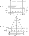
Figure 13 A, 13B, 14 and 15 diagrams by the example of the variable lens array of liquid crystal lens structure.Shown in Figure 13 A and 13B, lens arra comprises first transparency carrier 101 and second transparency carrier of being made by for example glass material 102, and is folded in the liquid crystal layer 103 between first substrate 101 and second substrate 102.First substrate 101 and second substrate 102 are arranged as with facing with each other apart from d therebetween.
Shown in Figure 14 and 15, be formed uniformly on the first basically whole surface of substrate 101 in the face of the side of second substrate 102 by first transparency electrode 111 of constructing such as the nesa coating of ITO film.And, shown in Figure 14 and 15, partly be formed on second substrate 102 in the face of on the side of first substrate 101 by second transparency electrode 112 of constructing such as the nesa coating of ITO film.Shown in figure 15, second transparency electrode 112 has for example electrode width L, and extends in the vertical.When producing lens effect, a plurality of second transparency electrodes 112 are arranged with the spaced and parallel corresponding to lens pitch p.Space between two adjacent second transparency electrodes 112 is the opening with width A.In addition, in Figure 15, in order to describe the layout of second electrode 112, diagram the state that is squeezed of variable lens array, in other words, first substrate 101 is positioned at upside, and second substrate 102 is positioned at downside.
In addition, the alignment film (not shown) is formed between first transparency electrode 111 and the liquid crystal layer 103.And alignment film is formed between second transparency electrode 112 and the liquid crystal layer 103 in an identical manner.In liquid crystal layer 103, the anisotropic liquid crystal molecule 104 of the refraction coefficient that distributes equably.
Shown in Figure 13 A, in lens arra, in applying the normality that voltage is 0V, liquid crystal molecule 104 as one man is oriented on the predetermined direction of being confirmed by alignment film.Therefore, the wave front 201 of transmitted ray is a plane wave, and lens arra becomes the state of no lens effect.On the other hand, in lens arra, shown in Figure 14 and 15, second transparency electrode 112 is furnished with the opening that width is A betwixt, thereby when under state shown in Figure 14, applying predetermined driving voltage, the Electric Field Distribution in the liquid crystal layer 103 of having setovered.More specifically, produce such electric field, its electric field intensity basis increases with driving voltage in the regional corresponding part that forms second transparency electrode 112, and along with to the minimizing of the distance of the core of the opening with width A and reduction gradually.Therefore, shown in Figure 13 B, the orientation of liquid crystal molecule 104 changes according to electric-field intensity distribution.Therefore, changed the wave front 202 of transmitted ray, made that lens arra converts the state that produces lens effect to through changing the refractive index distribution in the liquid crystal layer 103.
Summary of the invention
In adopting the three-dimensional display of lenticular lens systems, such as the flat-panel monitor of LCD usually as display device.In typical flat-panel monitor, the same with the situation of display panel 301 shown in Figure 16, sub-pixel 41R, 41G and the 41B of R, G and B color are arranged to vertical bar.In other words, the sub-pixel arrangements that sub-pixel 41R, 41G and the 41B of color is arranged so that same color in a longitudinal direction, and the subpixel period of different colours be arranged in a lateral direction.In Figure 16, diagram have the display panel 301 of such pixel structure and the most simply combining of cylindrical lens array 302, and the cylindrical axes of cylindrical lens 303 (central shaft) longitudinal direction that is parallel to display panel 301 combines and arranges.In addition, in Figure 16, X, Y and Z represent wherein to arrange the coordinate axis in the space of three-dimensional display.X1 and Y1 represent the coordinate axis on the display panel 301.In Figure 16; X-direction (horizontal direction) in the structure space is consistent with first change in coordinate axis direction (X1 direction of principal axis) on the display panel 301, and the Y direction (longitudinal direction) in the structure space is consistent with second change in coordinate axis direction (Y1 direction of principal axis) on the display panel 301.And in Figure 16, Px and Py represent pixel pitch and the pixel pitch on the longitudinal direction on the shorter direction of each sub-pixel 41R, 41G and 41B respectively.In Figure 16, each of sub-pixel 41R, 41G and 41B all has rectangular shape, and the longitudinal direction of rectangular shape is consistent with the Y1 direction of principal axis on the display panel 301.
In the layout of pixel structure shown in figure 16 and cylindrical lens array 302, the combination of arranging in the horizontal direction three subpixels 41R, 41G and 41B continuously is as the colored unit picture element (1 pixel) that shows.In the case, sub-pixel 41R, 41G and the 41B horizontal level in a pixel differs from one another, thereby sub-pixel 41R, 41G and the 41B of color have at cylindrical lens 303 on the horizontal direction of refracting power and expand.Therefore, have such problem: the difference between the color of the light position in the horizontal direction causes the vision that irregular colour is even when this color arrives beholder's eyes.And shading light part (black matrix) is arranged between the sub-pixel, thereby non-luminous part perceived as brightness irregularities.Three kinds of methods below known are as the solution of such problem.
(1) defocuses; Like " the Moire fringe reduction by optical filters in integral three-dimensionalimaging on a color flat-panel display " that Makoto Okui, Masaki Kobayashi Jun Arai and Fumio Okano deliver, APPLIED OPTICS, Vol.44; No.21; 2005, described in the p4475-4483
(2) adopt scatter plate; Like " the Moire fringe reduction by optical filters in integralthree-dimensional imaging on a color flat-panel display " that Makoto Okui, Masaki Kobayashi Jun Arai and FumioOkano deliver, APPLIED OPTICS, Vol.44; No.21; 2005, described in the p4475-4483
(3) adopt oblique lenticular lens systems, described in the open No.2005-309374 of japanese unexamined patent.
Method (1) is that the refracting power or the optical range of wherein cylindrical lens array 302 changes to cause the method that defocuses, and has mixed the color from the sub-pixel of each color thus, to prevent the even brightness irregularities of irregular colour.Method (2) is to arrange between display panel 301 and cylindrical lens array 302 that wherein scatter plate is to reduce the method for the even brightness irregularities of irregular colour.Yet in method (1) and (2), through defocusing or scattered light has destroyed the sharpness that is shown image, and such destruction that is shown on the image definition can cause the reduction of stereoeffect.
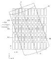
In method (3), shown in figure 18, utilize a plurality of sub-pixel 41R, 41G and the 41B that construct the colored unit picture element that shows, and each unit picture element is constructed by the combination of sub-pixel 41R, 41G and 41B on the vergence direction all two-dimentionally.And cylindrical lens 303 is arranged along the angle tilt ground that sub-pixel combines.In Figure 18, in the plane of the display surface that is parallel to display panel 301, the cylindrical axes of cylindrical lens 303 (central shaft) C1 tilts with angle θ from the Y direction of structure the space (it is consistent with the Y1 direction of principal axis of display panel 301 in the layout of Figure 18).In addition, in Figure 18, be assigned with equal number adjacent subpixels 41R, 41G and 41B (Ri, Gi and Bi, i=1,2,3 ...) combination form the colored unit picture element that shows.For example, the combination of sub-pixel (R2, G2 and B2) in an inclined direction adjacent one another are has formed unit picture element.In the method, sub-pixel 41R, 41G and the 41B of 1 pixel of structure are arranged in along cylindrical lens 303 not to have on the direction of cylindrical axes C1 of refracting power, thereby it is even that irregular colour does not take place.And, do not have blend color on the direction of refracting power at cylindrical lens 303, thereby the brightness in the shading light part 42 changes and is not discovered, and has eliminated brightness irregularities thus basically too little.
Under the situation of typical static demonstration, the always longitudinal direction of fixed mask and show state in a lateral direction.For example, under the situation of the static demonstration of screen horizontal orientation, show state always is fixed to horizontal orientation state shown in figure 16.Yet; For example; In such as recent mobile phones, developed such display: wherein the show state of the screen of display part can conversion between machine-direction oriented state (the long state of the height of screen in the depth-width ratio at screen) and horizontal orientation state (the long state of the width of screen in the depth-width ratio at screen).For example, be shown 90 ° of images through in being parallel to the plane of display surface, rotating 90 ° of whole device or display screens individually and also rotating, the conversion like this between machine-direction oriented show state and the horizontal orientation show state is attainable.What now, consider is to allow to carry out 3-D display in the device of between machine-direction oriented state and horizontal orientation state, changing.
Figure 17 diagram the example that under second arrangement states, is configured of three-dimensional display, the state of the arranged direction that this second arrangement states is a display panel 301 arranged direction half-twist of the display panel 301 in first arrangement states from Figure 16 in being parallel to the plane of display surface.In the case; Second change in coordinate axis direction on the display panel 301 (Y1 direction of principal axis) is consistent with the X-direction (horizontal direction) of structure in the space, and first change in coordinate axis direction on the display panel 301 (X1 direction of principal axis) is consistent with Y direction (longitudinal direction) in constructing the space.Therefore, sub-pixel 41R, 41G and the 41B of R, G and B color are arranged to horizontal bar.In other words, as the layout of sub-pixel 41R, 41G and the 41B of color, homochromy sub-pixel arrangements in a lateral direction, and the subpixel period of different colours ground is arranged in a longitudinal direction.In Figure 17, diagram have the display panel 301 of such pixel structure and the most simply combining of cylindrical lens array 302X.The combination of display panel 301 and cylindrical lens array 302X be arranged so that the cylindrical axes of each cylindrical lens 303X be parallel to X1 direction of principal axis on the display panel 301 (its with Figure 17 in the structure space of layout in Y direction consistent).
Under the situation that horizontal bar shown in figure 17 is arranged, the longitudinal direction (Y direction) in the structure space is gone up continuously the combination of three subpixels 41R, 41G and the 41B of R, G and the B color of layout as the colored unit picture element (1 pixel) that shows.In the case, the arranged direction of sub-pixel 41R, 41G and the 41B of the color in 1 pixel has the direction of refracting power perpendicular to cylindrical lens 303X, thereby it is even not produce irregular colour.Yet, still in the case, have the shading light part 42 between pixel, thereby brightness irregularities still arranged.
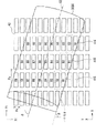
In horizontal bar is arranged, shown in figure 19, adopt oblique lenticular lens systems to eliminate irregularity in brightness.In Figure 19, the cylindrical axes of cylindrical lens 303X (central shaft) C2 with angle θ in the plane of the display surface that is parallel to display panel 301 from the Y direction of structure the space (it is consistent with the X1 direction of principal axis on the display panel 301 in the layout of Figure 19) inclination.When adopting oblique lenticular lens systems with the elimination irregularity in brightness, under the situation that horizontal bar is arranged, the sub-pixel pitch on the horizontal direction is greater than the sub-pixel pitch in the vertical bar deployment scenarios.In other words, the pixel pitch on shorter direction is Px, and the pixel pitch on the longitudinal direction is that Py is (during Py>Px); Under the situation that vertical bar is arranged; Sub-pixel pitch on the horizontal direction is Px, but under the situation that horizontal bar is arranged, the sub-pixel pitch on the horizontal direction is Py.Therefore, increase the tiltangle of cylindrical lens 303X, therefore be difficult to the anaglyph on the separation of level direction.In addition, in Figure 19, be assigned with equal number adjacent subpixels 41R, 41G and 41B (Ri, Gi and Bi, i=1,2,3 ...) combination form the colored unit picture element that shows.For example, the combination of sub-pixel (R2, G2 and B2) in an inclined direction adjacent one another are forms unit picture element.
In the structure example in Figure 19, sub-pixel 41R, 41G and the 41B of 1 pixel of structure is with the separation of 1 row and 1 row.Cylindrical lens 303X tiltangle at this moment is through θ=tan
-1(Py/Px) obtain.In typical display panel, the depth-width ratio of 1 pixel is 1: 1, thereby has set up Py=3Px.Therefore, the tiltangle of the cylindrical lens 303X among Figure 19 is 71.6 °.In the case, the refracting power on the vertical direction (Y direction) is greater than the refracting power on the horizontal direction (directions X), thereby the separation degree of the anaglyph on the vertical direction is greater than horizontal direction.In stereoscopic vision, the parallax on the horizontal direction is important, and therefore needing tiltangle is 45 ° or littler.Therefore, shown in the structure example among Figure 20, consider to reduce the method for the tiltangle of cylindrical lens 303X through in vertical direction distance between the sub-pixel 41R, 41G and the 41B that increase by 1 pixel of structure.
In the structure example in Figure 20, sub-pixel 41R, 41G and the 41B of 1 pixel of structure is with the separation of 4 row and 1 row.Therefore, the tiltangle of cylindrical lens 303X is through θ=tan
-1(Py/4Px) obtain.In the case, tiltangle is 36.9 ° because of Py=3Px, and has increased anaglyph separation degree in the horizontal direction.Yet, in the case, increased the distance between sub-pixel 41R, 41G and the 41B, therefore being difficult to discover sub-pixel 41R, 41G and 41B thus is 1 pixel, may perceive and guesses the image pictures different that is shown.
Therefore, consider in vertical bar layout and horizontal bar layout and construct under the situation of the two, be difficult to the even brightness irregularities of elimination irregular colour under the prerequisite of the stereoeffect of not breaking the ring stereo-picture as pixel.In other words, in the three-dimensional display that adopts lenticular lens systems, the problem below producing.As first problem, under the situation that vertical bar is arranged, produce the even brightness irregularities of irregular colour.This first problem is resolved through adopting oblique lenticular lens systems.As second problem, under the situation that horizontal bar is arranged, be not suitable for adopting oblique lenticular lens systems, thereby be difficult to eliminate brightness irregularities.
Lenticular lens systems in the prior art is used to realize allow under the situation that the stereo-picture of changing between machine-direction oriented state and the horizontal orientation state shows, is difficult to be implemented in be shown as the device that the even brightness irregularities of irregular colour does not take place under the two the situation of machine-direction oriented and horizontal orientation.
On the other hand, in stereo display,, may not expect most to adopt to be used for the display panel that common two dimension shows in order to eliminate the even brightness irregularities of irregular colour or the purpose of laying out pixel closely in the horizontal direction.For example, use is considered to effective like the display panel with specific pixel structure shown in Figure 21 described in the open No.2005-316372 of japanese unexamined patent.In pixel shown in Figure 21 structure, do not have in the horizontal direction the compartment of terrain be arranged in a plurality of colors on first horizontal line each sub-pixel and adjacent to the sub-pixel of the same color on first horizontal second horizontal line.
When adopting the display panel of pixel structure shown in Figure 21, obtain the effect identical and need not arrange obliquely that cylindrical lens array 302 eliminates the even brightness irregularities of irregular colour with oblique lenticular lens systems shown in Figure 180.Yet even adopt such display panel, but under the situation of display half-twist, shading light part 42 still occurs in vertical direction continuously, causes brightness irregularities thus.As long as in display panel, there is a shading light part 42, just be difficult to realize the pixel structure that the sub-pixel of each color is wherein arranged continuously under two kinds of situation of then machine-direction oriented and horizontal orientation at display.And, under the situation of arrangement states half-twist shown in Figure 21, increase the pixel pitch of horizontal direction at display, thereby be difficult in the horizontal direction closely laying out pixel.Therefore, tiltedly lenticular lens systems is not suitable for arrangement states, and is difficult to eliminate brightness irregularities.
Expectation provides such three-dimensional display, and it differs the good stereoscopic vision that 90 ° first arrangement states and second arrangement states allows to realize to have the even less brightness irregularities of less irregular colour in the two each other in arranged direction.
According to embodiments of the invention; The three-dimensional display that is provided comprises: display panel; Be configured to display image in convertible first arrangement states and second arrangement states each other, the arrangement states that this second arrangement states is defined as display panel wherein in the plane of the display surface that is parallel to display panel from the state of the arranged direction half-twist of display panel first arranges; And lens array device, being arranged as display surface, and comprising a plurality of cylindrical lenses in the face of display panel, these a plurality of cylindrical lenses are constructed to be arranged in parallel along the direction according to the arrangement states of display panel.When display panel is first arrangement states; A plurality of cylindrical lenses are arranged along horizontal direction parallel; Make the axle of cylindrical lens in being parallel to the plane of display surface, tilt from vertical direction; And when display panel was second arrangement states, a plurality of cylindrical lenses were arranged along horizontal direction parallel, make the axle of cylindrical lens be directed to the vertical direction in the plane that is parallel to display surface.And; Display panel has the pixel structure of a plurality of sub-pixel two-dimensional arrangement; Each of these a plurality of sub-pixels all shows each of required a plurality of colors corresponding to colour, and changes between first arrangement states and second arrangement states as the position that combines to be used to construct each sub-pixel of the colored unit picture element that shows.
In the three-dimensional display according to the embodiment of the invention, in display panel, one of two kinds of arrangement states that differ 90 ° each other through the arranged direction that changes to display panel arbitrarily show two dimensional image.When display panel was first arrangement states, a plurality of cylindrical lenses were arranged in parallel, and made the axle of cylindrical lens in being parallel to the plane of display surface, tilt from vertical direction.When display panel was second arrangement states, a plurality of cylindrical lenses were arranged along horizontal direction parallel in being parallel to the plane of display surface.And, change between first arrangement states and second arrangement states as the position of the combination of the sub-pixel of the colored unit picture element that shows.
In three-dimensional display according to the embodiment of the invention; As lens array device; For example; Variable liquid crystal lens array with liquid crystal layer is applicatory, and this liquid crystal layer is constructed to optionally produce the cylindrical lens effect as the effect of a plurality of cylindrical lenses, and the refractive index distribution that changes in the liquid crystal layer through electricity allows this cylindrical lens effect to be created on any one direction of two different directions.
In three-dimensional display according to the embodiment of the invention, the arranged direction of cylindrical lens and optimize according to the arrangement states of display panel as the combination of the sub-pixel of the colored unit picture element that shows, thus can realize good stereoscopic vision.In other words, in the arranged direction of display panel first arrangement states and second arrangement states of 90 ° of aberrations in the two each other, can realize having the good stereoscopic vision of the even less brightness irregularities of less irregular colour.
Through following description, of the present invention other with further target, feature and advantage will be more obviously understandable.
Description of drawings
Fig. 1 is the synoptic diagram of diagram according to relation between pixel arrangement in second arrangement states in the three-dimensional display of first embodiment of the invention and the cylindrical lens layout.
Fig. 2 is the synoptic diagram of diagram according to relation between pixel arrangement in first arrangement states in the three-dimensional display of first embodiment of the invention and the cylindrical lens layout.
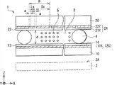
Fig. 3 is the sectional view of diagram according to the structure example of the three-dimensional display of first embodiment of the invention.
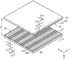
Fig. 4 is the skeleton view of diagram according to the structure example of the electrode part of the lens array device of the three-dimensional display of first embodiment of the invention.
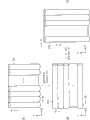
Fig. 5 be diagram apply state according to voltage in the lens array device of first embodiment of the invention and the lens effect that produced between the synoptic diagram of corresponding relation.
Fig. 6 (A) to (C) be optical equivalence be illustrated in synoptic diagram according to the state through adopting cylindrical lens convertible lens effect in the lens array device of first embodiment of the invention.
Fig. 7 (A) to (D) is the synoptic diagram of diagram according to the translation example between the show state in the three-dimensional display of first embodiment of the invention.
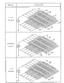
Fig. 8 (A) to (C) is diagram according to the synoptic diagram of the corresponding relation between electrode structure example in the lens array device of first embodiment of the invention and the lens effect that produced.
Fig. 9 (A) to (C) is diagram according to the synoptic diagram of the corresponding relation between another example of electrode structure in the lens array device of first embodiment of the invention and the lens effect that produced.
Figure 10 is the synoptic diagram of diagram according to the relation between pixel arrangement in second arrangement states in the three-dimensional display of second embodiment of the invention and the cylindrical lens layout.
Figure 11 is the synoptic diagram of diagram according to the relation between pixel arrangement in first arrangement states in the three-dimensional display of second embodiment of the invention and the cylindrical lens layout.
Figure 12 is the synoptic diagram through the notion of lenticular lens systems diagram three-dimensional display.
Figure 13 A and 13B be illustrated in respectively in the state of no lens effect with the state that produces lens effect in by the sectional view of the structure example of the variable lens array of liquid crystal lens structure.
Figure 14 is the sectional view of the structure example of electrode part in the liquid crystal lens shown in Figure 13 A and the 13B.
Figure 15 is the skeleton view of the structure example of electrode part in the liquid crystal lens shown in diagram Figure 13 A and the 13B.
Figure 16 is the synoptic diagram through the first layout example in the lenticular lens systems diagram three-dimensional display.
Figure 17 is the synoptic diagram through the second layout example in the lenticular lens systems diagram three-dimensional display.
Figure 18 is that the situation medium dip that is illustrated in the vertical bar pixel arrangement is arranged under the state of cylindrical lens, reduces the synoptic diagram of the even technological example of the even irregular colour of brightness disproportionation in the prior art.
Figure 19 arranges under the state of cylindrical lens in the situation medium dip of horizontal bar pixel arrangement, reduces the synoptic diagram of the even technological example of the even irregular colour of brightness disproportionation in the prior art.
Figure 20 be diagram wherein cylindrical lens be in tilted layout so that the pitch angle less than the synoptic diagram of the state of the layout among Figure 19.
Figure 21 is under the state that is illustrated in to the suitable laying out pixel of three-dimensional display, reduces the synoptic diagram of the even technological example of the even irregular colour of brightness disproportionation in the prior art.
Embodiment
Below, will be described in detail with reference to the attached drawings preferred embodiment.
First embodiment
The total structure of three-dimensional display
Fig. 3 diagram according to the structure example of the three-dimensional display of first embodiment of the invention.Three-dimensional display according to this embodiment comprises display panel 2 and lens array device 1, and display panel 2 allows to show two dimensional image that lens array device 1 is arranged as the display surface 2A in the face of display panel 2 generally.It is that one of first arrangement states and second arrangement states realize stereo display that three-dimensional display allows through changing 2 to two kinds of arrangement states of display panel.Second arrangement states is the arranged direction of display panel 2 state from the arranged direction half-twist of display panel 2 first arrangement states in the plane that is parallel to display surface 2A.And stereo display is convertible between two dimensional mode and the 3-D display pattern at two kinds of display modes.
In addition, in this embodiment, X, Y and Z represent wherein to arrange the coordinate axis in the space of three-dimensional display, and X1 and Y1 represent the coordinate axis of (on the display surface 2A) on the display panel 2.Unless otherwise noted, otherwise " horizontal direction " perhaps " horizontal direction " be meant the direction that is parallel to X-direction at structure in the space, and " longitudinal direction " perhaps " vertical direction " be meant the direction that is parallel to Y direction in the structure space.And, in this three-dimensional display, anaglyph on the X-direction of structure in the space separately and beholder's eyes be arranged under the situation on the X-direction in structure space, can realize stereoscopic vision.
And; In this embodiment; " first arrangement states " is meant that the X-direction in the structure space is consistent with first change in coordinate axis direction (X1 direction of principal axis) on the display panel 2, and the Y direction in the structure space is consistent with second change in coordinate axis direction (Y1 direction of principal axis) on the display panel 2.This state is corresponding to the arrangement states of prior art shown in Figure 16.In addition; " second arrangement states " is meant such state; X-direction in the structure space is consistent with second change in coordinate axis direction (Y1 direction of principal axis) on the display panel 2, and the Y direction in the structure space is consistent with first change in coordinate axis direction (X1 direction of principal axis) on the display panel 2.This state is corresponding to the arrangement states of prior art shown in Figure 17.
Lens array device 1 is the variable lens array that utilizes like the liquid crystal lens system that will describe after a while, and allows the open/close state of electric control lens effect.Lens array device 1 optionally changes the transmissive state from the light of display panel 2 through response display mode control lens effect.And; Lens array device 1 has like the described liquid crystal layer that is constructed to optionally produce the cylindrical lens effect after a while, and this cylindrical lens effect allows to change the refractive index distribution in the liquid crystal layer and on any one of two different directions, produce through electricity.
In addition, will describe the preferred arrangements direction of cylindrical lens of preferred pixel structure and the lens array device 1 of display panel 2 after a while in detail with reference to Fig. 1 and 2.
The total structure of lens array device 1
For essential structure and the effect of describing lens array device 1, at first, as an example, with describing such situation: the direction (arranged direction of cylindrical lens) that produces lens effect is changed differing each other between 90 ° longitudinal direction and the horizontal direction.
As shown in Figure 3, lens array device 1 comprises: first substrate 10 and second substrate 20, with facing with each other therebetween apart from d; And be arranged in the liquid crystal layer 3 between first substrate 10 and second substrate 20.First substrate 10 and second substrate 20 are transparency carriers, for example, are made by glass material or resin material.In the face of forming the first electrode group 14 on the side of second substrate 20, a plurality of transparency electrodes that extend on the first direction are arranged with the spaced and parallel on the Width in the first electrode group 14 at first substrate 10.Alignment film 13 is formed on first substrate 10, has the first electrode group 14 therebetween.In the face of forming the second electrode group 24 on the side of first substrate 10, a plurality of transparency electrodes that in the second electrode group 24, extend on the second direction different with first direction are arranged with the spaced and parallel on the Width at second substrate 20.Alignment film 23 is formed on second substrate 20, has the second electrode group 24 therebetween.
The electrode structure of lens array device 1
Fig. 4 diagram the structure example of electrode structure of lens array device 1.In Fig. 4, in order to be easy to discern the difference with the electrode structure of prior art shown in Figure 15, diagram the lens array device 1 inverted state among Fig. 3, in other words, first substrate 10 is arranged on upside, and second substrate 20 is arranged on downside.
Being configured to of the first electrode group 14, wherein as a plurality of transparency electrodes, two kinds of electrodes with different electrode widths alternately are arranged in parallel.In other words, the structure of the first electrode group 14 comprises a plurality of directions Xs first electrode (the first electrode 11X) and a plurality of directions X second electrode (the second electrode 12X) that alternately is arranged in parallel.Each of the first electrode 11X all has the first width Ly, and extends on the first direction (X1 direction of principal axis).Each of the second electrode 12X all has the second width S y greater than the first width Ly, and extends on the first direction.A plurality of first electrode 11X arrange with the spaced and parallel corresponding to the lens pitch p of the second cylindrical lens 31X that produces lens effect.The first electrode 11X and the second electrode 12X arrange with interval a.
The second electrode group 24 also has such structure, and wherein as a plurality of transparency electrodes, two kinds of electrodes with different electrode widths alternately are arranged in parallel.In other words, being configured to of the second electrode group 24: comprise a plurality of Y direction first electrodes (the first electrode 21Y) and a plurality of Y direction second electrode (the second electrode 22Y) that alternately are arranged in parallel.Each of the first electrode 21Y all has the first width Lx, and extends on the second direction (Y1 direction of principal axis).Each of the second electrode 22Y all has the second width S x greater than the first width Lx, and extends on the second direction.A plurality of first electrode 21Y arrange with the spaced and parallel corresponding to the lens pitch p of the first cylindrical lens 31Y that produces as lens effect.The first electrode 21Y and the second electrode 22Y arrange with interval a.
Make lens array device
When making lens array device 1; At first; For example, the nesa coating such as the ITO film is formed on first substrate of being made by for example glass material or resin material 10 and second substrate 20, to form the first electrode group 14 and the second electrode group 24 respectively with predetermined pattern.Alignment film 13 and 23 formation such as oblique evaporation method through rubbing manipulation or SiO rub such as the polymer compound of polyimide with cloth in rubbing manipulation in one direction.Therefore, the major axis of liquid crystal molecule 5 is oriented on the direction.In order to keep even apart from d between first substrate 10 and second substrate 20, printing and sealing material on alignment film 13 and 23 is dispersed with the spacer of being made by glass material or resin material 4 in the sealing material.Then, first substrate 10 and second substrate 20 are bonded together, and solidify the encapsulant that comprises spacer 4., from the opening of encapsulant first substrate 10 and second substrate 20 between inject known liquid crystal material, like TN liquid crystal or stn liquid crystal, then with the opening sealing of encapsulant thereafter.Then, liquid-crystal compsn is heated to its isotropic phase, slowly cools off then to accomplish lens array device 1.In addition, in this embodiment, the refraction coefficient anisotropy Δ n of liquid crystal molecule 5 is big more, and the lens effect of acquisition is big more, thereby liquid crystal material preferably has such component.On the other hand; Have at liquid-crystal compsn under the situation of big refraction coefficient anisotropy Δ n; Owing to the physical characteristics of having destroyed liquid-crystal compsn has increased viscosity; So can be difficult to liquid-crystal compsn is infused between the substrate, perhaps liquid-crystal compsn can become at low temperatures near the state of crystal form, perhaps possibly increase internal electric field and causes increasing the driving voltage that is used for the liquid crystal key element.Therefore, liquid crystal material preferably has based on the two component of manufacturability and lens effect.
The control operation of lens array device
Next, with reference to figure 5 and Fig. 6, will be described below the control operation (control operation of lens effect) of lens array device 1.Fig. 5 diagram in the lens array device 1 of annexation with electrode voltage apply the corresponding relation between the lens effect of state and generation.Show to Fig. 6 optical equivalence the lens effect that produces in the lens array device 1.
In lens array device 1, liquid crystal layer 3 changes over three kinds of states according to the state electricity of applying voltage for the first electrode group 14 and the second electrode group 24 does not promptly have one of the state of lens effect, first lens state and second lens state.First lens state is the state that produces the lens effect that extends in first cylindrical lens on the second direction (Y1 direction of principal axis).Second lens state is the state that produces the lens effect that extends in second cylindrical lens on the first direction (X1 direction of principal axis).
In lens array device 1; Become at liquid crystal layer 3 under the situation of no lens effect state, voltage becomes a plurality of transparency electrodes of the first electrode group 14 and a plurality of transparency electrodes of the second electrode group 24 have the voltage status (the graphic state of center section among Fig. 5) of same potential (0V).In the case, liquid crystal molecule 5 as one man is orientated with predetermined direction, and this predetermined direction is confirmed through the former reason alignment film 13 identical with the situation shown in Figure 13 A and 23, thereby liquid crystal layer 3 becomes the state of no lens effect.
And, becoming at liquid crystal layer 3 under the situation of first lens state, the predetermined potential that in the part corresponding to the first electrode 21Y of the second electrode group 24, is created between the transparency electrode of liquid crystal layer about in the of 3 is poor, and this electric potential difference is allowed the orientation that changes liquid crystal molecule 5.For example, utility voltage imposes on all a plurality of transparency electrodes of the first electrode group 14.At this moment, predetermined driving voltage only selectivity impose on the first electrode 21Y (graphic state in the top referring to Fig. 5) of a plurality of transparency electrodes of the second electrode group 24.In the case, the Electric Field Distribution in the liquid crystal layer 3 through with Figure 13 B in the identical principle of graphic situation be biased.More specifically, produce such electric field, the electric field intensity basis increases corresponding to the driving voltage on the part in the zone that forms the first electrode 21Y in this electric field, and reduces gradually along with the increase of the distance first electrode 21Y distance.In other words, Electric Field Distribution is changed at first direction (X1 direction of principal axis) and is gone up the generation lens effect.Shown in Fig. 6 (A), lens array device 1 becomes such lens state equivalently, wherein arranges a plurality of first cylindrical lenses (the Y direction cylindrical lens) 31Y that extends in the Y1 direction of principal axis and on the X1 direction of principal axis, have refracting power abreast along the X1 direction of principal axis.In the case, voltage only selectivity impose in the second electrode group 24 transparency electrode (the first electrode 21Y) corresponding to the position of the lens pitch p of the first cylindrical lens 31Y.
And, becoming at liquid crystal layer 3 under the situation of second lens state, the predetermined potential that in the part corresponding to the first electrode 11X of the first electrode group 14, is created between the transparency electrode of liquid crystal layer about in the of 3 is poor, and this electric potential difference allows the orientation change of liquid crystal molecule 5.For example, utility voltage imposes on all a plurality of transparency electrodes (the first electrode 21Y and the second electrode 22Y) of the second electrode group 24.At this moment, predetermined drive voltages only selectivity impose on the first electrode 11X (referring to the state shown in the bottom of Fig. 5) of a plurality of transparency electrodes (the first electrode 11X and the second electrode 12X) of the first electrode group 14.In the case, the Electric Field Distribution in the liquid crystal layer 3 is through the principle biasing identical with situation shown in Figure 13 B.More specifically, the electric field intensity of the electric field that produces basis increases corresponding to the driving voltage in the part in the zone that forms the first electrode 11X, and reduces gradually along with the increase of the distance first electrode 11X distance.In other words, Electric Field Distribution changes so that go up the generation lens effect in second direction (Y direction).Shown in Fig. 6 (B), lens array device 1 becomes such lens state equivalently, wherein arranges a plurality of second cylindrical lenses (directions X cylindrical lens) 31X that extends in the X1 direction of principal axis and on the Y1 direction of principal axis, have refracting power abreast along the Y1 direction of principal axis.In the case, voltage only selectivity impose in the first electrode group 14 transparency electrode (the first electrode 11X) corresponding to the position of the lens pitch p of the second cylindrical lens 31X.
In the first electrode group 14 and the second electrode group 24; Interval a between electrode width (Ly and Lx etc.) or electrode (for example can be equal to each other; Ly=Lx) time, allow to produce the cylindrical lens effect that has equal lens pitch p and the refracting power that equates in different directions.On the other hand, when the first electrode group 14 and the second electrode group 24 have different electrode widths or different electrode interbody spacer a, in first lens state and second lens state, allow to produce cylindrical lens effect with different lens pitch.
The control operation of three-dimensional display
With reference to figure 7, will be described below the control operation of the three-dimensional display that adopts lens array device 1.Fig. 7 diagram the example of show state conversion in the three-dimensional display.Here, as an example, for example will be described below such situation, wherein three-dimensional display is applied to the device of the for example mobile device that the show state of screen can change between machine-direction oriented state and horizontal orientation state.And, as an example, will be described below the situation that three-dimensional display can be changed between two dimensional mode and 3-D display pattern.
In three-dimensional display, the electricity conversion between two dimension demonstration and the 3-D display realizes through in above-mentioned no lens effect state, first lens state and second lens state, suitably changing.For example, when lens array device 1 becomes the state of no lens effect, see through, realize that thus two dimension shows from the display image not deflection of light and the former state of display panel 2.Fig. 7 (C) diagram such example screens; Wherein, the show state of screen realizes that two dimension shows in being the state (first arrangement states) of horizontal orientation; And Fig. 7 (D) diagram such example screens, wherein in the show state of screen is machine-direction oriented state (second arrangement states), realize that two dimension shows.
And; When lens array device 1 becomes first lens state; From the display image light deflection of display panel 2 on first direction (X1 direction of principal axis) perpendicular to second direction (Y1 direction of principal axis); Obtain 3-D display thus, wherein the eyes as the beholder obtain stereoeffect when first direction is located.This is corresponding to such situation: be that the state (first arrangement states) of the horizontal orientation shown in Fig. 7 (A) is realized 3-D display down at the show state of screen wherein.Under this state, produce the lens effect state under as Fig. 6 (A) shown in, thereby, be under the state of horizontal orientation at the show state of screen, when eyes direction (X-direction in the structure space) when locating transversely, acquisition stereoeffect.
In addition; When lens array device 1 becomes second lens state; On second direction (Y1 direction of principal axis), realize 3-D display from the display image light deflection of display panel 2 thus when eyes acquisition stereoeffect when second direction is located perpendicular to first direction (X1 direction of principal axis).This is corresponding to such situation: wherein the show state at screen is the 3-D display that realizes under the machine-direction oriented state shown in Fig. 7 (B).Under this state; Produced the lens effect under the state shown in Fig. 6 (C) (state shown in Fig. 6 (B) is the state of half-twist structurally); Thereby; Under the show state of screen is machine-direction oriented state,, obtain stereoeffect when eyes transversely during direction (X-direction in the structure space) location.
In lens array device 1, in an inclined direction produce the electrode structure example of lens effect
In Fig. 4,5 and 6, described such situation: the direction that wherein in lens array device 1, produces lens effect changes 90 ° from the longitudinal direction to the horizontal direction, perhaps vice versa.Yet the angle that direction changes is not limited to longitudinal direction and in a lateral direction 90 °, but this direction allows change arbitrarily angled.In other words, lens effect of the first cylindrical lens 31Y and the second cylindrical lens 31X one or both of allows to produce in an inclined direction.
Fig. 8 (A) diagram such electrode structure example, wherein compare with the electrode structure shown in the Figure 4 and 5, the second electrode group 24 (the first electrode 21Y and the second electrode 22Y) in display surface from longitudinal direction (Y1 direction of principal axis) tilt angle theta.When the second electrode group 24 tilts by this way, shown in Fig. 8 (B), in first lens state, allow the cylindrical lens effect is produced as central shaft (cylindrical axes) C1 with the effect of angle θ from the cylindrical lens of Y1 direction of principal axis inclination.In other words, equivalently, can construct such cylindrical lens array, wherein arrange a plurality of first cylindrical lens 31Y that central shaft (cylindrical axes) C1 tilts with angle θ from the Y1 direction of principal axis abreast.In addition; In second lens state; The same with the situation of Fig. 6 (B), lens array device 1 becomes such lens state equivalently: a plurality of second cylindrical lens 31X that wherein extend in the X1 direction of principal axis and on the Y1 direction of principal axis, have a refracting power arrange (with reference to figure 8 (C)) along the Y1 direction of principal axis abreast.
Fig. 9 (A) diagram such electrode structure example, wherein opposite with the electrode structure shown in the Figure 4 and 5, the first electrode group 14 (the first electrode 11X and the second electrode 12X) in display surface from horizontal direction (X1 direction of principal axis) tilt angle theta.When the first electrode group 14 tilts by this way, shown in Fig. 9 (C),, allow the cylindrical lens effect is produced as central shaft (cylindrical axes) C2 from the effect of X1 direction of principal axis with the cylindrical lens of angle θ inclination as second lens state.In other words, equivalently, can construct such cylindrical lens array, wherein arrange a plurality of second cylindrical lens 31X that central shaft (cylindrical axes) C2 tilts with angle θ from the X1 direction of principal axis abreast.In addition; In first lens state; The same with the situation of Fig. 6 (A), lens array device 1 becomes such lens state equivalently, and a plurality of first cylindrical lens 31Y that wherein extend in the Y1 direction of principal axis and on the X1 direction of principal axis, have a refracting power are along X1 direction of principal axis be arranged in parallel (referring to Fig. 9 (B)).
The pixel structure of display panel 2 and the arranged direction of cylindrical lens 31X and 31Y
Next, arrangement states that will be described below display panel 2 among this embodiment and preference relation between sub-pixel as the colored unit picture element that shows combines.Simultaneously, will be described below the arrangement states of display panel 2 and the preference relation between cylindrical lens 31X and the arranged direction of 31Y in lens array device 1.
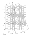
Fig. 1 diagram the relation between the layout of the second cylindrical lens 31X in pixel arrangement and the lens array device 1 in display panel 2 second arrangement states.Fig. 2 diagram the relation between the layout of the first cylindrical lens 31Y in pixel arrangement and the lens array device 1 in display panel 2 first arrangement states.Under the situation of display panel 2 in first arrangement states, as shown in Figure 2, in lens array device 1, a plurality of first cylindrical lens 31Y laterally arrange, and the axle of the cylindrical lens 31Y that wins is tilted from vertical direction in the plane that is parallel to display surface 2A.And as shown in Figure 1 under the situation of display panel 2 in second arrangement states, a plurality of second cylindrical lens 31X arrange along horizontal direction parallel, make the axle of the second cylindrical lens 31X in the plane that is parallel to display surface 2A, be directed to vertical direction.In addition, in lens array device 1,, can adopt the electrode structure shown in Fig. 8 (A) between such both direction for lens effect is changed.In other words, in first arrangement states, produce the lens effect under the state shown in Fig. 8 (B).Under second arrangement states, produce the lens effect down of state shown in Fig. 8 (C), and lens array device 1 is with display panel 2 half-twist structurally, the second cylindrical lens 31X is arranged in parallel along the X-direction of constructing in the space thus.
In this embodiment, in first arrangement states (referring to Fig. 2), in display panel 2, form along the pixel structure of sub-pixel 41R, 41G and the 41B of perpendicular line (on Y direction) periodic arrangement color.And, in second arrangement states (referring to Fig. 1), be formed on the pixel structure of (on X-direction) periodic arrangement sub-pixel 41R, 41G and 41B on the horizontal line.Simultaneously, under second arrangement states, form the pixel arrangement that the sub-pixel of same color on sub-pixel and second horizontal line adjacent with this first horizontal line of the color on first horizontal line does not have the compartment of terrain to arrange in the horizontal direction.For example, in Fig. 1, note the shade and the outstanding red pieces pixel 41R that shows that represent by Reference numeral R1, R2, R3 and R4.Therefore, clearly, the sub-pixel of each color does not have the compartment of terrain to arrange in the horizontal direction continuously.
In Fig. 1 and 2, be assigned with equal number sub-pixel 41R, 41G and 41B (Ri, Gi and Bi, i=1,2,3 ...) combination form the colored unit picture element that shows.In each of Fig. 1 and 2, for example, the combination of sub-pixel in an inclined direction adjacent one another are (R2, G2 and B2) forms unit picture element.
In other words, as shown in Figure 1 under second arrangement states, the combination that is arranged in sub-pixel 41R, 41G and the 41B of the different colours on the corresponding different water horizontal line is used as the colored unit picture element that shows.In first arrangement states, as shown in Figure 2, the combination that is arranged on sub-pixel 41R, 41G and the 41B of the different colours on the corresponding different vertical line is used as the colored unit picture element that shows.
In such pixel structure, under second arrangement states, sub-pixel 41R, 41G and the 41B of each color is connected so that part overlaps each other, and shading light part 42 occurs in vertical direction discontinuously.Therefore, under second arrangement states, eliminated the even brightness irregularities of irregular colour and need not arrange the second cylindrical lens 31X obliquely.Therefore, different with structure example among Figure 19 under second arrangement states, do not take place since the big pitch angle of the second cylindrical lens 31X and tiltedly lenticular lens systems be difficult to separate the problem of anaglyph.
On the other hand, in first arrangement states, the first cylindrical lens 31Y that tilts allows to eliminate the even brightness irregularities of irregular colour thus to utilize oblique lenticular lens systems.In the case, when the tiltangle of the first cylindrical lens 31Y is too big, because the oblique shortcoming of lenticular lens systems, be difficult to separate the problem of anaglyph.Therefore, tiltangle preferably satisfies following conditions.
In display panel 2, each of sub-pixel 41R, 41G and the 41B of color all has the rectangular shape of identical size.So; Display panel 2 has such pixel arrangement: wherein under first arrangement states (referring to Fig. 2); The longitudinal direction of each sub-pixel 41R, 41G and 41B is along vertical direction; And under second arrangement states (referring to Fig. 1), the shorter direction of each sub-pixel 41R, 41G and 41B is along vertical direction.At this moment, the pixel pitch of the shorter direction of each sub-pixel 41R, 41G and 41B and longitudinal direction is defined as Px and Py respectively.And the pixel wide on shorter direction and the longitudinal direction is defined as Wx and Wy respectively.In addition, in second arranged, as the unit picture element that is used for stereo-picture, the quantity of in vertical direction sub-pixel 41R, 41G and the 41B of structure " voxel " was N." voxel " is made up of pixel groups, and the quantity of pixel groups equals the parallax numbers in the three-dimensional display.Under second arrangement states, not at interval and do not overlap each other, the pixel wide Wy on the longitudinal direction must satisfy following relational expression for sub-pixel 41R, 41G or the 41B of same color are arranged in the horizontal direction continuously:
Wy=Py(1-1/N)
In first arrangement states, the tiltangle of constructing the preferred first cylindrical lens 31Y as pixel is that the distance between 45 ° or littler and the sub-pixel is very little.In pixel arrangement shown in Figure 2, when the combination of sub-pixel 41R, 41G and 41B (R1, G2 and B3) is used as the unit picture element of colored demonstration, obtain tiltangle through following relational expression:
θ=tan
-1((Py-Wy)/Px)
In the case, as stated, obtain the pixel wide Wy on the longitudinal direction through Wy=Py (1-1/N), so that tiltangle is 53.1 °, this angle is too big.Therefore, as the combination of sub-pixel 41R, 41G and 41B, preferably do not overlap each other in vertical direction and with the combination of the sub-pixel (R1, G1 and B1) arranged apart from very little each other distance.At this moment, obtain the tiltangle of the first cylindrical lens 31Y through following formula:
θ=tan
-1(Px/Py(1+1/N))
At this moment, under the situation of Py=3Px, tiltangle is 14.9 °, and this is to realize the anaglyph degree of separation value of very big state in the horizontal direction.In other words, tiltangle has the enough values that realize stereoscopic vision in the horizontal direction.
As stated, in this embodiment, optimized the arranged direction of cylindrical lens and as the combination of the sub-pixel of the colored unit picture element that shows according to the arrangement states of display panel 2, thereby can realize good stereoscopic vision.In other words, differ each other in the arranged direction of display panel 2 under 90 ° the two the situation of first arrangement states and second arrangement states, can realize the natural stereoscopic vision of the even less brightness irregularities of less irregular colour.Therefore; Be applied to the device that the display part can be changed at three-dimensional display between machine-direction oriented state and horizontal orientation state according to this embodiment; Such as; Be used under the situation of the portable display of portable phone, digital camera etc. for example, can realize longitudinal direction and not have the stereoscopic vision of unevenness in a lateral direction.
Second embodiment
Next, will be described below three-dimensional display according to second embodiment of the invention.With represent by identical Reference numeral according to the identical parts of the three-dimensional display of first embodiment, and be not described further.
In the three-dimensional display according to this embodiment, display panel 2 has the pixels with different structure with three-dimensional display according to first embodiment.The layout angle of the cylindrical lens of lens array device 1 is corresponding to this pixel structure.According to other essential structure of the three-dimensional display of second embodiment with identical according to the three-dimensional display of first embodiment.
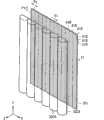
Figure 10 shows according to the relation between the layout of the second cylindrical lens 31X of pixel arrangement in 2 second arrangement states of display panel in the three-dimensional display of this embodiment and lens array device 1.Figure 11 diagram the relation between the layout of the first cylindrical lens 31Y of pixel arrangement and the lens array device 1 in display panel 2 first arrangement states.And, in this embodiment, under the situation of display panel 2 in first arrangement states; Shown in figure 11; In lens array device 1, arrange a plurality of first cylindrical lens 31Y abreast, make the axle of cylindrical lens 31Y in the plane that is parallel to display surface 2A, tilt from vertical direction.And, be under the situation under second arrangement states at display panel 2, shown in figure 10, a plurality of second cylindrical lens 31X arrange along horizontal direction parallel, make the axle of the second cylindrical lens 31X be directed to the vertical direction in the plane that is parallel to display surface 2A.In addition, still in this embodiment,, can adopt the electrode structure shown in Fig. 8 (A) between such both direction in order in lens array device 1, lens effect to be changed.In other words, producing the lens effect under the state shown in Fig. 8 (B) under first arrangement states.Under second arrangement states, produce the lens effect down of state shown in Fig. 8 (C), and lens array device 1 is with display panel 2 half-twist structurally, the second cylindrical lens 31X laterally arranges along the X-direction of constructing in the space thus.
In this embodiment, under the situation of (referring to Figure 10) under second arrangement states, the pixel of display panel 2 is configured to: wherein the combination of sub-pixel 43R, 43G and the 43B of the different colours of the colored unit picture element that shows of structure is arranged as the formation triangular arrangement.And under the situation of (referring to Figure 11) under first arrangement states, the combination that is arranged in sub-pixel 43R, 43G and the 43B of the different colours on the corresponding different vertical line is used as the colored unit picture element that shows.
In Figure 10 and 11, be assigned with equal number adjacent subpixels 43R, 43G and 43B (Ri, Gi and Bi, i=1,2,3 ...) combination form the colored unit picture element that shows.In each of Figure 10 and 11, for example, the combination of sub-pixel 43R, 43G and the 43B (R2, G2 and B2) that is centered on by dotted line forms unit picture element.
In such pixel structure, under second arrangement states, unit picture element be configured to triangular arrangement, and sub-pixel 43R, 43G and the 43B of color arrange two-dimentionally.Therefore, to have reduced irregular colour even for the diffusion effect (diffusion effect) through the second cylindrical lens 31X.And shading light part 42 occurs in vertical direction discontinuously, thereby permission is eliminated the even brightness irregularities of irregular colour and need not be arranged the second cylindrical lens 31X obliquely.Therefore, different with structure example among Figure 19 under the situation of second arrangement states, oblique lenticular lens systems is difficult to separate anaglyph owing to the big pitch angle of the second cylindrical lens 31X problem does not take place.
On the other hand, in first arrangement states, the first cylindrical lens 31Y that tilts allows to eliminate the even brightness irregularities of irregular colour thus to utilize oblique lenticular lens systems.In the case, when the tiltangle of the first cylindrical lens 31Y is too big,, produces and be difficult to the separately problem of anaglyph as the shortcoming of oblique lenticular lens systems.Therefore, tiltangle preferably satisfies following conditions.
In display panel 2, each of sub-pixel 43R, 43G and the 43B of color all has the square shape of identical size.Then, under first arrangement states (referring to Figure 11), horizontal direction and the pixel pitch on the vertical direction of each sub-pixel 43R, 43G and 43B are defined as Px and Py respectively.And the pixel wide on horizontal direction and the vertical direction is defined as Wx and Wy respectively.Under the situation of first arrangement states, as the pixel structure, the tiltangle of the preferred first cylindrical lens 31Y is 45 ° or littler, and the distance between the sub-pixel is little.In the case, in pixel arrangement shown in Figure 11, when the combination that is arranged on sub-pixel 43R, 43G and 43B (R1, G3 and B5) on the tilted direction continuously is used as the unit picture element of colored demonstration, obtain tiltangle through following formula:
θ=tan
-1(2Px/Wy)
In the case, in triangular arrangement, when each the depth-width ratio of sub-pixel 43R, 43G and the 43B of each color is 1: 1, confirm Wx=Wy and Px=Py, and tiltangle because of Wx<Px greater than 45 °.Therefore, as the combination of sub-pixel 43R, 43G and 43B, preferably do not overlap each other in vertical direction and the combination of the sub-pixel (R1, G1 and B1) arranged with small distance each other.At this moment, obtain the tiltangle of the first cylindrical lens 31Y through following formula:
θ=tan
-1(Wx/(2Py+Wy/2))
At this moment, each of Wx and Wy all has arbitrary value, but approximates under the situation of Py (Py ≈ Wy) at Wy, confirms θ=tan
-1(2/5), tiltangle is about 21.8 ° thus.Therefore, tiltangle has such value: the very big in the horizontal direction state of degree of separation that under this value, can realize anaglyph.In other words, tiltangle has the enough values that obtain stereoscopic vision in the horizontal direction.
As stated, still in this embodiment, the arranged direction of cylindrical lens and optimize according to the arrangement states of display panel 2 as the combination of the sub-pixel of the colored unit picture element that shows, thus can realize good stereoscopic vision.In other words, differ 90 ° first arrangement states and second arrangement states each other in the two, can realize even less and the natural stereoscopic vision that brightness irregularities is less of irregular colour in the arranged direction of display panel 2.Particularly, in this embodiment,, adopt typical triangular arrangement, thereby be easy to obtain the effect identical and do not adopt the special pixel structure shown in Fig. 1 and 2 with first embodiment as the pixel of display panel 2 structure.
The present invention comprise with the japanese priority patent application JP 2009-097371 that is submitted to Jap.P. office on April 13rd, 2009 in disclosed relevant theme, its full content is incorporated into this by reference.
Those skilled in the art should be understood that, according to design demand and other factors, can carry out various modifications, combination, part combination and replacement, as long as they are in the scope of accompanying claims or its equivalent.
Claims (5)
1. three-dimensional display comprises:
Display panel; Be configured to display image in first arrangement states that can change each other and second arrangement states, said second arrangement states is defined as such state: the arranged direction of said display panel in the plane of the display surface that is parallel to said display panel from the arranged direction half-twist of said display panel said first arrangement states; And
Lens array device is arranged as the display surface in the face of said display panel, and comprises a plurality of cylindrical lenses, and said a plurality of cylindrical lenses are constructed to be arranged in parallel along the direction according to the said arrangement states of said display panel,
Wherein when said display panel is said first arrangement states; Said a plurality of cylindrical lens is arranged along horizontal direction parallel; Make the axle of said cylindrical lens in being parallel to the plane of said display surface, tilt, and when said display panel was said second arrangement states, said a plurality of cylindrical lenses were arranged along said horizontal direction parallel from vertical direction; Make the said axle of said cylindrical lens in being parallel to the plane of said display surface, be directed to vertical direction, and
Said display panel has the pixel structure that a plurality of sub-pixels are arranged two-dimentionally; Each of said a plurality of sub-pixels shows each of required a plurality of colors corresponding to colour; And the position in conjunction with each sub-pixel that is used to construct the colored unit picture element that shows changes between said first arrangement states and said second arrangement states
Wherein said lens array device is the variable liquid crystal lens array with liquid crystal layer; Said variable liquid crystal lens array is constructed to optionally produce the cylindrical lens effect of the effect that is equivalent to said a plurality of cylindrical lenses, and the refractive index distribution that changes in the said liquid crystal layer through electricity allows said cylindrical lens effect to be created on any direction of two different directions.
2. three-dimensional display according to claim 1, wherein
When said display panel is said first arrangement states; The said sub-pixel of said a plurality of colors is arranged along perpendicular line periodically; And when said display panel is said second arrangement states; The said sub-pixel of said a plurality of colors arranges along horizontal line periodically, and the sub-pixel of the color on first horizontal line and adjacent to the sub-pixel arrangements of the same color on said first horizontal second horizontal line be on said horizontal direction not at interval, and
When said display panel is said second arrangement states; The combination that is arranged in the sub-pixel of the different colours on the corresponding different water horizontal line is used as the colored said unit picture element that shows; And when said display panel was said first arrangement states, the combination of sub-pixel that is arranged in the different colours on the corresponding different vertical line was as the colored said unit picture element that shows.
3. three-dimensional display according to claim 2, wherein
Said sub-pixel in the said display panel has rectangular shape,
When said display panel was said first arrangement states, the longitudinal direction of said sub-pixel was consistent with said vertical direction, and when said display panel was said second arrangement states, the shorter direction of said sub-pixel was consistent with said vertical direction,
Relational expression below pixel wide Wy on the said longitudinal direction satisfies:
Wy=Py (1-1/N), and
Angle θ satisfies following expression:
θ=tan
-1(Px/Py(1+1/N)),
Wherein Px and Py represent the said shorter direction of said sub-pixel and the pixel pitch on the said longitudinal direction respectively,
Wy representes the pixel wide of said sub-pixel on said longitudinal direction,
θ is illustrated in the pitch angle of the said axle of said cylindrical lens under said first arrangement states with respect to the said vertical direction of said display panel, and
N is illustrated in the quantity of sub-pixel on said vertical direction under said second arrangement states, and said sub-pixel structure voxel is as the unit picture element of stereo-picture.
4. three-dimensional display according to claim 1, wherein
When said display panel was said second arrangement states, the combination of the sub-pixel of the different colours of the colored said unit picture element that shows of structure was arranged as the formation triangular arrangement, and
When said display panel was said first arrangement states, the combination of sub-pixel that is arranged in the different colours on the corresponding different vertical line was as the colored said unit picture element that shows.
5. three-dimensional display according to claim 4, wherein
Said sub-pixel in the said display panel has the square shape, and
Angle θ satisfies following expression:
θ=tan
-1(Wx/(2Py+Wy/2)),
Wherein θ is illustrated in the pitch angle of the said axle of said cylindrical lens under said first arrangement states with respect to the said vertical direction of said display panel,
Py representes said sub-pixel pixel pitch in vertical direction, and
Wx and Wy be illustrated respectively in said sub-pixel under said first arrangement states in the horizontal direction with vertical direction on pixel wide.
Applications Claiming Priority (2)
| Application Number | Priority Date | Filing Date | Title |
|---|---|---|---|
| JP097371/09 | 2009-04-13 | ||
| JP2009097371A JP5521380B2 (en) | 2009-04-13 | 2009-04-13 | 3D display device |
Publications (2)
| Publication Number | Publication Date |
|---|---|
| CN101859028A CN101859028A (en) | 2010-10-13 |
| CN101859028B true CN101859028B (en) | 2012-12-26 |
Family
ID=42934095
Family Applications (1)
| Application Number | Title | Priority Date | Filing Date |
|---|---|---|---|
| CN2010101585739A Expired - Fee Related CN101859028B (en) | 2009-04-13 | 2010-04-07 | Stereoscopic display |
Country Status (3)
| Country | Link |
|---|---|
| US (2) | US8436953B2 (en) |
| JP (1) | JP5521380B2 (en) |
| CN (1) | CN101859028B (en) |
Families Citing this family (82)
| Publication number | Priority date | Publication date | Assignee | Title |
|---|---|---|---|---|
| RU2490817C2 (en) | 2008-02-11 | 2013-08-20 | Конинклейке Филипс Электроникс Н.В. | Autostereoscopic image output device |
| JP5396944B2 (en) * | 2008-12-22 | 2014-01-22 | ソニー株式会社 | Lens array element and image display device |
| BR112012029368B1 (en) * | 2010-05-21 | 2020-11-24 | Koninklijke Philips N.V. | display device, switchable between a simple view mode and a multiview mode and method for controlling the lens function of a lenticular lens of a self-stereoscopic display device |
| JP5170230B2 (en) * | 2010-12-17 | 2013-03-27 | 株式会社Jvcケンウッド | Autostereoscopic display device |
| JP5321575B2 (en) * | 2010-12-17 | 2013-10-23 | 株式会社Jvcケンウッド | Autostereoscopic display device |
| TWI569041B (en) | 2011-02-14 | 2017-02-01 | 半導體能源研究所股份有限公司 | Display device |
| EP2490451A1 (en) * | 2011-02-18 | 2012-08-22 | Koninklijke Philips Electronics N.V. | Autostereoscopic display device |
| CN102096231B (en) * | 2011-02-24 | 2012-11-07 | 华映视讯(吴江)有限公司 | Three-dimensional display with changeable parallax barrier pattern |
| US9443455B2 (en) * | 2011-02-25 | 2016-09-13 | Semiconductor Energy Laboratory Co., Ltd. | Display device having a plurality of pixels |
| JP2012189885A (en) * | 2011-03-11 | 2012-10-04 | Japan Display West Co Ltd | Display device |
| TWI432857B (en) * | 2011-05-18 | 2014-04-01 | Juilan Yu | Rotatable 3d display |
| WO2012176102A1 (en) * | 2011-06-22 | 2012-12-27 | Koninklijke Philips Electronics N.V. | Autostereoscopic display device |
| JP2014167493A (en) * | 2011-06-22 | 2014-09-11 | Sharp Corp | Stereoscopic image display device |
| JP5774701B2 (en) * | 2011-07-28 | 2015-09-09 | 株式会社東芝 | Liquid crystal optical element and image display device |
| CN103748874B (en) * | 2011-08-24 | 2017-03-22 | 皇家飞利浦有限公司 | Autostereoscopic display device |
| JP2013045087A (en) * | 2011-08-26 | 2013-03-04 | Toshiba Corp | Three-dimensional image display apparatus |
| JP5197814B2 (en) * | 2011-08-29 | 2013-05-15 | 株式会社東芝 | 3D image display device |
| JPWO2013038557A1 (en) * | 2011-09-16 | 2015-03-23 | 株式会社東芝 | Gradient index liquid crystal optical element and image display device |
| CN103733129A (en) * | 2011-09-16 | 2014-04-16 | 株式会社东芝 | Gradient index liquid crystal optical element and image display device |
| JP5639983B2 (en) * | 2011-10-25 | 2014-12-10 | 株式会社ジャパンディスプレイ | 3D image display device |
| CN102364391B (en) * | 2011-11-04 | 2015-11-25 | 深圳超多维光电子有限公司 | Stereoscopic display device and method |
| KR20130053103A (en) * | 2011-11-15 | 2013-05-23 | 삼성디스플레이 주식회사 | Display panel and display apparatus having the same |
| US9036107B2 (en) * | 2011-11-18 | 2015-05-19 | Shenzhen China Star Optoelectronics Technology Co., Ltd. | Flat panel display device, stereoscopic display device, plasma display device |
| KR20130055997A (en) * | 2011-11-21 | 2013-05-29 | 삼성디스플레이 주식회사 | 3-dimensional image display device |
| TW201323926A (en) * | 2011-12-07 | 2013-06-16 | Chunghwa Picture Tubes Ltd | Three-dimensional image display device |
| JP5253563B2 (en) * | 2011-12-09 | 2013-07-31 | 株式会社東芝 | 3D image display device and display method |
| TWI452342B (en) * | 2011-12-15 | 2014-09-11 | Delta Electronics Inc | Autostereoscopic display apparatus |
| KR101937865B1 (en) * | 2012-02-09 | 2019-01-15 | 삼성디스플레이 주식회사 | Liquid crytal lens panel, display device having the same |
| JP2013182186A (en) * | 2012-03-02 | 2013-09-12 | Japan Display West Co Ltd | Display device, electronic device and sticking structure |
| JP5597661B2 (en) * | 2012-03-05 | 2014-10-01 | 株式会社東芝 | Image display device |
| TWI467536B (en) * | 2012-03-08 | 2015-01-01 | Chunghwa Picture Tubes Ltd | Auto stereoscopic display apparatus |
| TWI454791B (en) | 2012-05-23 | 2014-10-01 | Au Optronics Corp | Electrically-driven liquid crystal lens panel and stereoscopic display panel |
| WO2013175785A1 (en) * | 2012-05-23 | 2013-11-28 | パナソニック株式会社 | Image display device |
| JP5320488B1 (en) * | 2012-05-29 | 2013-10-23 | 株式会社東芝 | 3D image display apparatus and 3D image display method |
| TWI453465B (en) * | 2012-07-02 | 2014-09-21 | Chunghwa Picture Tubes Ltd | Stereo display apparatus |
| FR2994044B1 (en) * | 2012-07-24 | 2017-05-12 | Alioscopy | SELESTHETICALLY DISPLAYED METHOD ON A SCREEN HAVING ITS GREATEST DIMENSION IN THE VERTICAL DIRECTION. |
| KR101335526B1 (en) * | 2012-09-12 | 2013-12-02 | 엘지디스플레이 주식회사 | Stereoscopic image display |
| KR20140053740A (en) * | 2012-10-26 | 2014-05-08 | 삼성디스플레이 주식회사 | Display apparatus and method for driving the display apparatus |
| CN102928988B (en) * | 2012-11-06 | 2015-07-15 | 深圳市华星光电技术有限公司 | Three-dimensional display device, liquid crystal lens and driving method thereof |
| US8854560B2 (en) * | 2012-11-06 | 2014-10-07 | Shenzhen China Star Optoelectronics Technology Co., Ltd | Auto-stereoscopic display device, liquid crystal lens, and driving method thereof |
| JP6028975B2 (en) * | 2012-12-05 | 2016-11-24 | Nltテクノロジー株式会社 | Stereoscopic image display device |
| CN103913922A (en) * | 2013-01-06 | 2014-07-09 | 东莞万士达液晶显示器有限公司 | Display device capable of switching two-dimensional display mode and three-dimensional display mode and liquid crystal lens thereof |
| JP6277544B2 (en) * | 2013-02-27 | 2018-02-14 | Tianma Japan株式会社 | Stereoscopic image display device and terminal device |
| EP2976673B1 (en) * | 2013-03-22 | 2016-09-21 | Koninklijke Philips N.V. | Autostereoscopic display device |
| KR102040653B1 (en) * | 2013-04-08 | 2019-11-06 | 엘지디스플레이 주식회사 | Holography 3D Display Device |
| JP6130727B2 (en) | 2013-05-16 | 2017-05-17 | 株式会社東芝 | Liquid crystal optical device and image display device |
| EP3004967B1 (en) * | 2013-06-03 | 2019-10-02 | Koninklijke Philips N.V. | Multi-view display device |
| JPWO2014196125A1 (en) * | 2013-06-05 | 2017-02-23 | パナソニックIpマネジメント株式会社 | Image display device and liquid crystal lens |
| JP2015001614A (en) * | 2013-06-14 | 2015-01-05 | 株式会社ジャパンディスプレイ | Display device |
| CN103412409B (en) * | 2013-07-01 | 2015-12-23 | 深圳超多维光电子有限公司 | Stereo display method and 3 d display device |
| KR20150008712A (en) * | 2013-07-15 | 2015-01-23 | 삼성디스플레이 주식회사 | Signal processing method, signal processor, and display device comprsing the signal processor |
| CN104345459A (en) * | 2013-08-01 | 2015-02-11 | 大昱光电股份有限公司 | Stereoscopic displaying apparatus |
| JP6169482B2 (en) * | 2013-11-15 | 2017-07-26 | 株式会社ジャパンディスプレイ | Liquid crystal device, electronic apparatus, and liquid crystal device manufacturing method |
| CN103945203A (en) * | 2013-12-19 | 2014-07-23 | 上海天马微电子有限公司 | Stereo image display device |
| CA2933951A1 (en) | 2013-12-20 | 2015-06-25 | Koninklijke Philips N.V. | Autostereoscopic display device |
| KR102144733B1 (en) | 2013-12-30 | 2020-08-18 | 엘지디스플레이 주식회사 | Stereopsis image display device |
| JP2015145920A (en) | 2014-01-31 | 2015-08-13 | 株式会社東芝 | image display device |
| TWI521497B (en) * | 2014-02-11 | 2016-02-11 | 友達光電股份有限公司 | Liquid crystal lens |
| TWI561855B (en) * | 2014-04-10 | 2016-12-11 | Au Optronics Corp | 3-d display device |
| KR102214355B1 (en) | 2014-06-16 | 2021-02-09 | 삼성디스플레이 주식회사 | Three dimensional image display device |
| CN104166259B (en) | 2014-07-30 | 2017-02-08 | 京东方科技集团股份有限公司 | Display substrate, driving method thereof and display device |
| CN104267525B (en) * | 2014-08-18 | 2018-05-11 | 深圳市华星光电技术有限公司 | 3 d display device and preparation method thereof |
| CN104238164A (en) * | 2014-09-02 | 2014-12-24 | 深圳超多维光电子有限公司 | 3D (three-dimensional) display device |
| TWI533665B (en) * | 2014-09-02 | 2016-05-11 | 深圳超多維光電子有限公司 | Stereoscopic display device |
| KR20160028596A (en) | 2014-09-03 | 2016-03-14 | 삼성디스플레이 주식회사 | Three dimensional image display device |
| KR102221773B1 (en) | 2014-09-04 | 2021-03-02 | 삼성디스플레이 주식회사 | Three dimensional image display device |
| JP5960224B2 (en) * | 2014-10-15 | 2016-08-02 | 株式会社ジャパンディスプレイ | Liquid crystal display |
| CN104360520A (en) * | 2014-11-18 | 2015-02-18 | 深圳市华星光电技术有限公司 | Touch display module and display device |
| WO2016102338A1 (en) | 2014-12-24 | 2016-06-30 | Koninklijke Philips N.V. | Autostereoscopic display device |
| CN104570370B (en) | 2015-02-05 | 2017-02-22 | 京东方科技集团股份有限公司 | 3D (three-dimensional) display device |
| CN104597609A (en) * | 2015-02-06 | 2015-05-06 | 京东方科技集团股份有限公司 | Pixel array, display device and display method |
| CN104635398A (en) * | 2015-03-09 | 2015-05-20 | 京东方科技集团股份有限公司 | Display device and grating control method |
| KR102463171B1 (en) | 2015-12-24 | 2022-11-04 | 삼성전자주식회사 | Optical layer and desplay device including the same |
| KR20170089472A (en) * | 2016-01-26 | 2017-08-04 | 삼성디스플레이 주식회사 | 3-dimensional image display device and method for driving the same |
| CN105700164B (en) * | 2016-04-12 | 2018-05-11 | 武汉华星光电技术有限公司 | A kind of 3D display module and 3D display device |
| KR101880751B1 (en) * | 2017-03-21 | 2018-07-20 | 주식회사 모픽 | Method for reducing error by allignment of lenticular lens and user terminal for displaying glass free stereoscopic image and the user terminal of perporming the method |
| JP6264493B1 (en) * | 2017-05-19 | 2018-01-24 | 大日本印刷株式会社 | Display device |
| CN107065211A (en) * | 2017-06-07 | 2017-08-18 | 孝感市青谷信息科技有限公司 | Bore hole 3D image displays |
| CN107942525B (en) * | 2017-12-22 | 2021-02-02 | 张家港康得新光电材料有限公司 | Display device |
| KR20210085442A (en) * | 2019-12-30 | 2021-07-08 | 엘지디스플레이 주식회사 | 3D display apparatus having lenticular lens |
| KR20210086354A (en) * | 2019-12-31 | 2021-07-08 | 엘지디스플레이 주식회사 | 3D display apparatus having lenticular lens |
| TWI741524B (en) * | 2020-03-10 | 2021-10-01 | 友達光電股份有限公司 | Display device |
Citations (3)
| Publication number | Priority date | Publication date | Assignee | Title |
|---|---|---|---|---|
| CN101218833A (en) * | 2005-07-14 | 2008-07-09 | 皇家飞利浦电子股份有限公司 | Autostereoscopic display apparatus |
| US20080266387A1 (en) * | 2005-12-20 | 2008-10-30 | Koninklijke Philips Electronics, N.V. | Autostereoscopic Display Device |
| CN101331776A (en) * | 2005-12-13 | 2008-12-24 | 皇家飞利浦电子股份有限公司 | Display device |
Family Cites Families (9)
| Publication number | Priority date | Publication date | Assignee | Title |
|---|---|---|---|---|
| GB2278223A (en) * | 1993-05-21 | 1994-11-23 | Sharp Kk | Spatial light modulator and directional display |
| GB9513658D0 (en) * | 1995-07-05 | 1995-09-06 | Philips Electronics Uk Ltd | Autostereoscopic display apparatus |
| US6064424A (en) * | 1996-02-23 | 2000-05-16 | U.S. Philips Corporation | Autostereoscopic display apparatus |
| GB2317734A (en) * | 1996-09-30 | 1998-04-01 | Sharp Kk | Spatial light modulator and directional display |
| GB2403815A (en) * | 2003-07-10 | 2005-01-12 | Ocuity Ltd | Birefringent lens array structure |
| JP3885077B2 (en) | 2004-03-26 | 2007-02-21 | 独立行政法人科学技術振興機構 | 3D display |
| JP4402578B2 (en) | 2004-03-31 | 2010-01-20 | 独立行政法人科学技術振興機構 | 3D display |
| KR100728115B1 (en) * | 2005-11-04 | 2007-06-13 | 삼성에스디아이 주식회사 | Three-dimensional display device and driving method thereof |
| JP5396944B2 (en) * | 2008-12-22 | 2014-01-22 | ソニー株式会社 | Lens array element and image display device |
-
2009
- 2009-04-13 JP JP2009097371A patent/JP5521380B2/en not_active Expired - Fee Related
-
2010
- 2010-03-19 US US12/727,951 patent/US8436953B2/en not_active Expired - Fee Related
- 2010-04-07 CN CN2010101585739A patent/CN101859028B/en not_active Expired - Fee Related
-
2013
- 2013-01-11 US US13/739,424 patent/US8638402B2/en not_active Expired - Fee Related
Patent Citations (3)
| Publication number | Priority date | Publication date | Assignee | Title |
|---|---|---|---|---|
| CN101218833A (en) * | 2005-07-14 | 2008-07-09 | 皇家飞利浦电子股份有限公司 | Autostereoscopic display apparatus |
| CN101331776A (en) * | 2005-12-13 | 2008-12-24 | 皇家飞利浦电子股份有限公司 | Display device |
| US20080266387A1 (en) * | 2005-12-20 | 2008-10-30 | Koninklijke Philips Electronics, N.V. | Autostereoscopic Display Device |
Also Published As
| Publication number | Publication date |
|---|---|
| JP5521380B2 (en) | 2014-06-11 |
| US8436953B2 (en) | 2013-05-07 |
| US20100259697A1 (en) | 2010-10-14 |
| CN101859028A (en) | 2010-10-13 |
| US8638402B2 (en) | 2014-01-28 |
| JP2010249954A (en) | 2010-11-04 |
| US20130128162A1 (en) | 2013-05-23 |
Similar Documents
| Publication | Publication Date | Title |
|---|---|---|
| CN101859028B (en) | Stereoscopic display | |
| US11442315B2 (en) | Liquid crystal display device comprising a first pixel for displaying a first-viewpoint image and a second pixel for displaying a second-viewpoint image | |
| CN102598671B (en) | Autostereoscopic display device and control method thereof | |
| CN102116988B (en) | Electrically-driven liquid crystal lens and stereoscopic display device using the same | |
| CN101995667B (en) | Stereoscopic image displaying apparatus | |
| CN102109715B (en) | Autostereoscopic display apparatus | |
| RU2598158C2 (en) | Autostereoscopic displaying device with optical zoom | |
| CN103163652B (en) | Polarized glass type stereoscopic image display | |
| CN103995361A (en) | Naked eye 3D display pixel unit and multi-view naked eye 3D image display device | |
| US8587737B2 (en) | Display device | |
| CN102279469B (en) | Parallax system, panel, device, display method and computer readable medium | |
| JP2004206089A (en) | Multiple view display | |
| CN101840072A (en) | Automatic three-dimensional image display device | |
| CN102749713A (en) | Display device | |
| CN102356424A (en) | Methods of driving colour sequential displays | |
| CN203930226U (en) | Bore hole 3D display pixel cells and many views bore hole 3D rendering display device | |
| JP2013045087A (en) | Three-dimensional image display apparatus | |
| CN103323980A (en) | Display device and electronic device | |
| CN102375272A (en) | Light barrier device and display unit | |
| CN102804027A (en) | Autostereoscopic display device | |
| CN105979247B (en) | Stereoscopic display | |
| CN104267525B (en) | 3 d display device and preparation method thereof | |
| CN102998827A (en) | Display device, display method, and electronic apparatus | |
| KR20120095035A (en) | Stereoscopic image display device | |
| JP6665291B2 (en) | Display device and display control method |
Legal Events
| Date | Code | Title | Description |
|---|---|---|---|
| C06 | Publication | ||
| PB01 | Publication | ||
| C10 | Entry into substantive examination | ||
| SE01 | Entry into force of request for substantive examination | ||
| C14 | Grant of patent or utility model | ||
| GR01 | Patent grant | ||
| CF01 | Termination of patent right due to non-payment of annual fee |
Granted publication date: 20121226 Termination date: 20150407 |
|
| EXPY | Termination of patent right or utility model |