Disclosure of Invention
The invention aims to solve the first technical problem of providing a special grinding machine for thrust bearing pads, which can quickly and conveniently remove oil dirt on the babbit alloy surface of the pads, repair scratches and unevenness on the surface of the thrust bearing pads, ensure the consistent thickness of the whole set of thrust bearing pads, and keep the surface of the pads smooth and smooth, the smooth finish and the smoothness consistency.
The technical problem to be solved can be implemented by the following technical scheme.
A thrust bearing pad sharpening machine comprises
A shoe positioning mechanism; the pad positioning mechanism is used for positioning a group of pads to be polished and keeping the polished surface of each pad facing to the same surface;
a grinding tool positioning mechanism; the grinding tool positioning mechanism is used for positioning a grinding tool selected for grinding the tile, and at least one grinding surface of the grinding tool is kept to be matched with the grinding surface of the tile to be ground positioned by the tile positioning mechanism;
a drive mechanism; the driving mechanism is used for driving at least one of the pad positioning mechanism and the grinding tool positioning mechanism to move relatively relative to the other, and at least one grinding surface of the grinding tool is kept to be in contact with the grinding surface of the pad.
As a further improvement of the technical scheme, the tile positioning mechanism is a positioning turntable, the tiles to be polished are dispersedly arranged on the surface of the positioning turntable, and the positioning turntable comprises a positioning rotating shaft; the driving mechanism is a rotating mechanism, and a rotating shaft of the rotating mechanism is connected with a positioning rotating shaft of the positioning turntable.
As a further improvement of the technical solution, a pin shaft is disposed at one end of the positioning rotating shaft of the positioning rotary table, a pin sleeve adapted to the pin shaft is sleeved at one end of the rotating mechanism rotating shaft, the pin sleeve is supported by a spring sleeved on the rotating mechanism rotating shaft, and the adapted pin sleeve and the pin shaft are cooperatively connected to the positioning rotary table and the rotating mechanism.
Wherein, the grinding tool of the grinding tool positioning mechanism can be a grinding disc or a grinding disc.
As one of the preferred embodiments of the present invention, the grinding plate may be configured as a laminated structure, for example, the laminated grinding plate has a hard substrate layer in the middle and an industrial scouring pad surface layer and a wood pulp spunlace nonwoven fabric surface layer on both sides. When in use, the grinding surface layers on the two sides can be flexibly selected according to the dirt and abrasion conditions of the babbit alloy surface or the grinding surfaces on the two sides can be used in an alternate mode.
As a further improvement of the present invention, the grinding machine may further include a pressing mechanism for adjusting a pressing gap between the grinding surface of the pad and the grinding surface of the grinding tool.
Wherein the pressing mechanism may comprise an adjusting nut.
In addition, the outer edge of the adjusting nut can be provided with a pressure scale line, and the friction force between the lower babbit metal surface and the grinding surface of the grinding tool and the grinding speed and quality of the grinding are controlled by the pressing mechanism by reading and controlling the related pressure value reflected and indicated by the pressure scale line.
Also as one of the preferred embodiments of the present invention, the rotating mechanism is a bevel gear transmission mechanism, and a rotating hand wheel can be connected to a driving gear shaft of the bevel gear transmission mechanism for the convenience of control and operation. The driving gear and the driven gear of the bevel gear transmission mechanism can be meshed in a crossed-axis or crossed-axis mode of orthogonal transmission or oblique transmission. For example, when the form of the crossed axes of the orthogonal drive is present, a right angle drive of exactly 90 degrees can be performed.
In addition, tile positioning clamping grooves can be formed in the positioning rotary disc and can be used for embedding the tile positioning clamping grooves in the positioning rotary disc.
Similarly, for the convenience and the firmness of the positioning of the tiles, a magnetic adsorption piece can be arranged on the surface of the positioning turntable to further adsorb and stabilize the positioning of the tiles.
The invention also aims to provide a method for repairing a tile by applying the sharpening machine; in order to achieve the purpose, the invention adopts the following technical scheme.
The pad repairing method of the thrust bearing pad sharpening machine, which is provided by the technical scheme, comprises the following steps:
(1) positioning the tiles to be polished, and keeping the positioning reference surfaces of the tiles consistent and the polished surfaces in the same direction;
(2) selecting a corresponding grinding tool and a corresponding grinding surface according to the dirt and abrasion conditions of the grinding surface of the tile block;
(3) positioning the selected grinding tool and the ground surface;
(4) and driving the driving mechanism to enable the grinding surface of the grinding tool to act on the grinding surface of the tile.
As a further improvement of the repairing method, the method can also comprise the step of adjusting the magnitude of the acting force between the grinding surface of the grinding tool and the grinding surface of the pad. The speed and quality control during repair is realized by adjusting the acting force.
As a further improvement of the repairing method, the method can also comprise the step of spraying cleaning agent on the grinding surface of the grinding tool, for example, when only some stains attached to the babbitt metal surface are to be cleaned, better cleaning effect can be realized by selecting a soft grinding surface and combining the cleaning agent.
By adopting the thrust bearing pad coping machine and the repairing method of the technical scheme, oil dirt on the babbit alloy surface of the pad can be quickly removed, scratches and unevenness on the surface of the thrust bearing pad can be repaired, the consistency of the thickness of the whole group of thrust bearing pads and the consistency of the flatness, smoothness and finish of each thrust bearing pad can be ensured, the problems existing in the past repairing pads are solved, the service performance of the repaired pads and the repeated use of the pads are ensured, and the aim of the invention is completely achieved.
Detailed Description
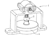
The thrust bearing pad sharpening machine and the application thereof as shown in figures 1 to 10 comprise a sharpening machine and a method for repairing pads by adopting the sharpening machine.
The pad sharpening machine utilizes the hand wheel 103 in the rotating mechanism 1 to drive the right-angle gear to enable the vertical shaft 1028 to rotate, then the vertical shaft 1028 drives the turntable 3 which is pressed on the disc base 104 and embedded with pads to rotate, the bottom of the turntable 3 is provided with the special abrasive disc 401, and the pads can rub with the abrasive disc to be sharpened through the rotation of the turntable 3.
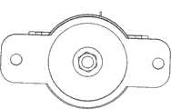
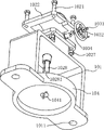
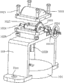
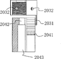
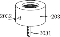
The pad sharpening machine comprises a rotating mechanism 1, a pressing mechanism 2, a rotating disc 3 and a base 4 (see fig. 1, 2 and 4). The rotating mechanism 1 is composed of a frame 101, a right-angle gear box 102, a hand wheel 103 and a disc base 104, the hand wheel 103 is connected with a threaded hole 10231, the transverse shaft 1023 rotates to drive a bevel gear 1025 on the transverse shaft 1023 to rotate, and the bevel gear 1025 on the transverse shaft 1023 rotates to drive a bevel gear on a vertical shaft 1028 to rotate and then drive the vertical shaft 1028 to rotate, so that the right-angle turning effect is achieved (wherein a copper bush 1024 is also arranged on the transverse shaft 1023). The lower portion of the vertical shaft 1028 is designed as a square shaft for driving the transition sleeve 204 to rotate, and the cylindrical middle portion of the transition sleeve 204 is designed as two large and small square through holes (i.e. square embedding holes 2042 and 2043 in fig. 5), which has the advantage that the large square embedding hole 2043 can fix the anti-falling panel 2051 on the square shaft for preventing the transition sleeve 204 from falling off after the rotary table 3 is pulled out. Transition sleeve 204, washer 201, spring 202, adjusting cap 203, anti-slip panel 2051 and screw 2052 form compression mechanism 2. The tightness of the spring 202 can be adjusted by the adjusting cap 203, according to the principle of spring compression, the tightness is equal to the pressing force of the adjusting turntable, and the pressure can be seen from the pressure scale 2031 on the adjusting cap.
Alternatively, the orthogonal bevel gear transmission comprising the gears connected to the horizontal axis 1023 and the vertical axis 1028 may be replaced by an orthogonal axis.
The repair method mainly comprises two methods: physical repair and chemical repair; mainly aims at oil dirt, scratches, hard spots and flatness on the surface of the Babbitt metal, determines what abrasive disc is repaired and applied according to the reality, and selects physical repair or chemical repair to process according to the condition of the surface of the Babbitt metal. The grinding sheet is in a detachable design which is convenient to replace, and the grinding material is selected from reusable and washable industrial scouring pad, wood pulp spunlace non-woven fabric and the like.
Physical repair is a coping method adopted for repairing scratches, hard sintered points and flatness on the surface of a tile. In order to ensure that the original effect and the smoothness of the tile surface are achieved, the abrasive disc 401 is formed by organically combining special high-strength fibers and grinding ore sand, has a unique open type net-shaped three-dimensional structure and elastic grinding characteristics, has the characteristics of no damage to workpieces, smooth surface treatment effect, difficult blockage, long service life, water resistance, oil resistance and strong self-sharpening performance, continuously loses the fibers in the grinding process, and continuously and naturally forms new grinding ore sand, so that a non-woven cloth grinding product with consistent quality can be provided for the tile surface, namely, an industrial scouring pad 4012 shown in fig. 3 is adhered to one surface of a base plate/an intermediate plate 4011 made of a hard material; the grain size of the industrial scouring pad 4012 is selected according to the surface condition requirement of the Babbitt metal, and the grinding sheet of the machine is made of four types of industrial scouring pads, namely 180#, 320#, 600#, and 1200 #. During application, the model of the grinding disc is selected according to the depth of scratches and the height of a sintered hard point, the pressing force of the adjusting rotary disc 3 is adjusted (which grid can be obtained by experience according to the surface condition of the tile), and the whole set of tiles are simultaneously polished on the grinding disc through the rotation of the rotary disc 3, so that the minimum loss of the Babbitt metal surface of the tiles is reduced, and the effects of surface smoothness and quick repair are achieved. Because the whole group of tiles are embedded on the turntable 3 and are rotationally polished on a plane, the repaired tiles achieve the purposes of consistent thickness, consistent flatness, smooth surface and consistent finish.
Chemical remediation is a rotary scrubbing process used to address oil stains adhering to the surface of the pad. In order to avoid damaging the original babbit surface of the tile, the abrasive disc 401 is made of wood pulp spunlace nonwoven 4013 which has unique absorption capacity, liquid absorption capacity, excellent longitudinal and transverse tension, high-efficiency water stain removal, oil stain removal, dissolution resistance, dust resistance, softness, no fiber shedding, no generation of fiber scraps, wiping quality guarantee, static resistance, no damage to the surface of an object, toughness, durability and the like, and is adhered to the other surface of the base plate/middle plate 4011 made of a hard material (see also fig. 3).
In application, the pressing force of the rotary disc 3 is adjusted according to the adhesion degree of the oil dirt, a non-toxic, tasteless and PH value neutral oil dirt cleaning agent is sprayed on the wood pulp spunlace non-woven fabric 4013, and the whole set of tiles are scrubbed on the abrasive disc simultaneously by rotating the rotary disc 3, so that the purpose of quickly and conveniently removing the oil dirt on the surface of the Babbitt metal without damaging the surface of the original Babbitt metal is achieved.
The rotating mechanism 1 is a framework and a transmission source of the whole pad sharpening machine and plays a role in driving the pad turntable to rotate, fixing the grinding piece and supporting the whole pad repairing machine. The device consists of a frame 101, a right-angle gear box 102 and a disc base 104, wherein the right-angle gear box 102 is used for changing the direction of a right angle by rotating a hand wheel assembly (comprising a hand wheel 103, a screw 1031, a gasket 1032 and a pin 1034) so as to enable a vertical shaft 1028 to rotate, and the disc base 104 is used for fixing a grinding disc. In order to enhance the grinding stability of the tile repairing machine, two fixing holes 1011 are designed on two sides of a base of the tile repairing machine, and the whole machine can be fixed on a workbench.
The right-angle gear case 102 is configured such that a lower case 1026 having an upper case cover 1022 and a frame 101 integrated with each other is coupled by bolts 1021 and nuts 1027, and a group of transmission members such as a bevel gear 1025 is enclosed in the right-angle gear case 102.
The lower part of the vertical shaft 1028 is square in design and has a threaded hole 10281 at the bottom for driving the rotation of the tile-inlaid turning disc 3 and the installation of the anti-drop part (i.e. the anti-drop panel 2051 and the screw 2052) of the pressing mechanism 2.
The disc base 104 is used for mounting the grinding plate 3, and in order to prevent the grinding plate 3 from following rotation, notches are formed in two sides of the center line of the rotation preventing hole 1041 in the middle of the disc base 104, so that insertion of protruding keys on two sides of a rotation preventing screw 4021 for fixing the grinding plate 3 is facilitated (see fig. 4).
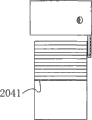
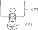
The pressing mechanism 2 is mainly connected with the vertical shaft 1028 on the rotating mechanism 1 and the rotating disc 3 through the transition sleeve 204, and drives the rotating disc 3 to rotate. The pressing mechanism utilizes the characteristics of the spring 202 to achieve the pressing force of the adjusting turntable 3 through the adjusting cap 203, and in order to facilitate empirical pressure identification of pad grinding, a graduated pressure scale 2031 is welded on the adjusting cap 203, and a circle of scale defining line (namely scale line 2041) is engraved on the transition sleeve 204. In order to prevent the transition sleeve 204 and other parts of the pressing mechanism from falling off after the rotating disk 3 is pulled out, a retaining panel 2051 and a screw 2052 are added in the design of the pressing mechanism, and the retaining panel 2051 is fixed at the lower end of the vertical shaft 1028 by screwing the screw 2052, so that the transition sleeve 204 can move up and down on the square shaft of the vertical shaft 1028 without falling off (see fig. 5).
The adjusting cap 203 is coupled to the transition sleeve 204 by an internal thread, and the tightness of the adjusting spring (which is substantially an adjusting nut) is adjusted by screwing in and screwing out (moving up and down) of the thread, in order to grasp the tightness of the spring 202, a graduated pressure scale 2031 is welded on the lower round edge of the adjusting cap 203, each turn is a grid scale, and the force applying hole 2032 on the adjusting cap 203 can be used for inserting and applying force to rotate a round rod (see fig. 5).
The transition sleeve 204 is cylindrical, the external thread of the upper part is connected with the internal thread of the adjusting cap 203, and a circle of scale defining line (namely, the scale line 2041) is engraved at the lower part of the thread. The middle part is provided with a large square embedding hole 2042 and a small square embedding hole 2043 which are through holes at the upper part and the lower part, the square embedding hole 2042 at the upper part is smaller and similar to the square shaft at the lower part of the vertical shaft 1028 of the rotating mechanism 1 (the size can be slightly larger for matching), and the square embedding hole is sleeved on the square shaft at the lower part of the vertical shaft 1028 and is convenient for moving up and down. The lower square embedding hole 2043 is larger than the square embedding hole 2042, and is similar to (about larger than) the size of the anti-falling panel 2051 and the square embedding 31 on the rotary table 3, so that the anti-falling panel 2051 can be embedded and fixed by the screw 2052 conveniently, and the square embedding 31 on the rotary table 3 can be embedded conveniently, so that the vertical shaft 1028 and the rotary table 3 can be connected, and the rotary table 3 can be driven to rotate (see fig. 5).
The anti-dropping panel 2051 and the screw 2052 (see fig. 5) are used for fixing the anti-dropping panel 2051 screwed on by the screw 2052 at the lower part of the vertical shaft 1028, so as to prevent the dropping problem of the parts of the pressing mechanism such as the transition sleeve 204 when the rotary disc 3 is drawn out to replace the tile to be repaired.
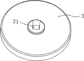
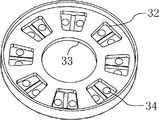
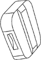
The rotary disc 3 (see fig. 6) is the only part for extracting and inserting the inlaid tile of the whole tile sharpening machine; the top of the transition sleeve is provided with a square insert 31 inserted into a square hole of the transition sleeve 204, the bottom of the transition sleeve is provided with a round concave hole, the size of the concave hole is similar to that of the disc base 104 (about larger than that of the concave hole), and the circular edge of the rotary disc 3 is mainly ensured to be protruded, so that the disc base 104 can be covered, and the rotary disc 3 is prevented from shaking when rotating. A deep central hole 33 is formed in the middle of the bottom of the entire turntable 3 to avoid frictional contact with the cap of the rotation preventing screw 4021 for mounting the grinding plate 3. What is essential is the eight pad holes 32 in the bottom of the disk 3, which are made entirely according to the pad pattern of fig. 7, so that the pads can be easily inserted into the pad holes 32 and protrude (higher) than the pad holes 32, which facilitates the frictional contact of the babbitt surface with the abrasive sheet and not with other parts. In order to ensure the adsorption force of the tile embedded in the tile hole 32 and prevent the tile from falling off easily, the magnetic sheets 34 are embedded on two sides of the middle groove in the tile hole, and the design comprehensively considers the safety of the tile when the turntable embedded with the tile is mounted on or dismounted from the coping device. The pad hole 32 is mainly used for fixing and clamping the pad to be ground, and can be arranged into a groove shape or other forms according to the pad structure.
The grinding plate assembly (see fig. 8 and 3) is composed of a special grinding plate 401, and an anti-rotation bolt assembly 402 (including an anti-rotation screw 4021, a washer 4022 and a nut 4023). The middle of the abrasive disc is made of hard material (a substrate 4011), in order to adapt to different surface conditions of the tile for treatment, the front surface of the abrasive disc is adhered to the substrate 4011 by adopting industrial scouring pad 4012 with complete granularity, and the back surface of the abrasive disc is adhered to the substrate 4011 by adopting wood pulp spunlace non-woven fabric 4013 made of superfine synthetic fibers; thus, one grinding sheet can achieve different grinding effects. The anti-rotation screws 4021 and the grinding plate 401 are both in an anti-rotation design, the rotation following phenomenon of the grinding plate 401 can be avoided when the turntable 3 drives the tile to rotate and grind, and the effect of grinding the tile is optimized.
Referring to fig. 9 and 10 in conjunction with fig. 1 to 8, a method of repairing a pad using the thrust bearing pad dresser will be described. The following examples are provided to list the relevant repair steps for dirty wear of the pad, respectively, and are mainly distinguished by the choice of grinding surfaces and the repeated coping with a plurality of grinding surfaces.
The first embodiment is as follows:
firstly, installing a rotating mechanism 1 and a pressing mechanism 2 of a thrust bearing pad sharpening machine in place;
secondly, checking the condition of the babbitt metal surface of the tile to be polished;
thirdly, selecting one surface of the grinding plate 401 and the industrial scouring pad 4012 or the spunlace non-woven fabric 4013 of the grinding plate as a grinding surface according to the condition of the babbitt metal surface of the pad to be ground;
fourthly, fixing the selected abrasive disc and the abrasive disc with the upward facing surface on the disc base 104 by using the anti-rotation bolt assembly 402;
fifthly, embedding the whole set of the tiles to be polished into the tile holes 32 of the turntable 3 (note that the Babbitt metal surface of the tiles to be polished faces downwards);
sixthly, lifting the transition sleeve 204 upwards according to the direction of an arrow A in the figure;
seventhly, the turntable 3 is put in place and sleeved on the disc base 104 according to the direction of an arrow B in the figure, and the transition sleeve 204 is put down and sleeved on the turntable square insert 31;
adjusting the adjusting cap 203 according to the condition of the tile to be polished, namely adjusting the pressing force of the turntable 3;
ninthly, rotating the hand wheel 103 to grind the whole group of tiles. (see FIG. 9, same below)
Example two:
firstly, installing a rotating mechanism 1 and a pressing mechanism 2 of a thrust bearing pad sharpening machine in place;
secondly, the babbit surface of the tile to be polished in the embodiment has deep scratches (which can not exceed 1/3(0.4mm) of the babbit plating layer or obvious hard point salient points are sintered;
thirdly, selecting 180# industrial scouring pad with the abrasive disc surface facing upwards, and fixing the abrasive disc surface on the disc base 104 by using an anti-rotation bolt assembly 402 for physical repair;
fourthly, embedding the whole set of the tiles to be polished into the tile holes 32 of the turntable 3 (note that the Babbitt metal surfaces of the tiles face downwards);
fifthly, lifting the transition sleeve 204 upwards (according to the direction of an arrow A in the figure);
sixthly, the turntable is sleeved on the disk base 104 in place, the transition sleeve 204 is put down and sleeved on the turntable square insert 31;
seventhly, increasing the pressing force of the adjusting turntable 3, and adjusting the adjusting cap 203 to 4-5 grids (scale degrees are from top to bottom);
turning a hand wheel 103 to grind the whole group of tiles for the first time until scratches or bumps of the grinding blocks are ground flat;
ninthly, replacing the grinding sheet of the 1200# industrial cleaning cloth, adjusting the adjusting cap 203 to 0-1 grid, and performing smooth and clean treatment on the surface of the tile block.
Example three:
firstly, installing a rotating mechanism 1 and a pressing mechanism 2 of a thrust bearing pad sharpening machine in place;
secondly, scratches on the surface of the Babbitt alloy of the tile to be polished are shallow or hard point salient points are not obviously sintered;
thirdly, the grinding sheet of the industrial scouring pad 320# or 600# can be selected to face upwards and fixed on the disc base 104 by the anti-rotating bolt assembly 402 for physical repair;
fourthly, embedding the whole set of the tiles to be polished into the tile holes 32 of the turntable 3 (note that the Babbitt metal surfaces of the tiles face downwards);
fifthly, lifting the transition sleeve 204 upwards;
sixthly, the turntable 3 is sleeved on the disc base 104 in place, the transition sleeve 204 is put down and sleeved on the turntable square insert 31;
seventhly, increasing the pressing force of the adjusting rotary table 3, and adjusting the adjusting cap 203 to 3-4 grids;
turning a hand wheel 103 to grind the whole group of tiles for the first time until scratches or bumps of the grinding blocks are ground flat;
ninthly, replacing the grinding sheet of the 1200# industrial cleaning cloth, adjusting the adjusting cap 203 to 0-1 grid, and performing smooth and clean treatment on the surface of the tile block.
Example four:
firstly, installing a rotating mechanism 1 and a pressing mechanism 2 of a thrust bearing pad sharpening machine in place;
secondly, the surface of the Babbitt metal of the tile to be polished in the embodiment is accumulated and adhered with flake oil dirt;
thirdly, selecting a wood pulp spunlace non-woven fabric 4013, fixing the wood pulp spunlace non-woven fabric 4013 on the disc base 104 by using an anti-rotation bolt assembly 402, and spraying an oil dirt cleaning agent on the surface of the non-woven fabric;
fourthly, embedding the whole set of tiles to be scrubbed into the tile holes 32 of the turntable 3 (note that the Babbitt metal surfaces of the tiles face downwards);
fifthly, lifting the transition sleeve 204 upwards;
sixthly, the turntable 3 is sleeved on the disc base 104 in place, the transition sleeve 204 is put down and sleeved on the turntable square insert 31;
seventhly, increasing the pressing force of the adjusting rotary disc, and adjusting the adjusting cap to 1-3 grids;
and eighthly, rotating the hand wheel 103 to rotate and scrub the whole group of tiles until the adhered oil dirt is wiped out.
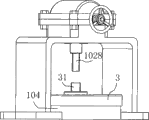
As shown in fig. 10, which is a schematic view of the mechanism when only the turntable 3 is mounted on the disk base and the pressing mechanism is not mounted, it can be seen that the square insert 31 of the turntable is positioned to face the vertical shaft 1028 of the rotating mechanism.
And the grinding disc in the invention can flexibly adopt other grinding parts such as a grinding disc and the like. Meanwhile, the relative displacement of the grinding tool relative to the tiles can adopt the relative rotation grinding mode and the translation mode, and only the grinding tool and the tiles are respectively fixed relatively and the grinding degree among the tiles in a group of tiles is kept to be equivalent.
The thrust bearing pad sharpening machine and the repairing method not only can be designed for repairing the thrust bearing pad for a high-pressure centrifugal pump (a phosphorus removal pump), but also can be applied to other pad type thrust bearings, and only the shape and the size of the pad embedded in the sharpening machine are different.