CN101846849B - Color conversion sheet, illumination device, and display device - Google Patents
Color conversion sheet, illumination device, and display device Download PDFInfo
- Publication number
- CN101846849B CN101846849B CN2010101345468A CN201010134546A CN101846849B CN 101846849 B CN101846849 B CN 101846849B CN 2010101345468 A CN2010101345468 A CN 2010101345468A CN 201010134546 A CN201010134546 A CN 201010134546A CN 101846849 B CN101846849 B CN 101846849B
- Authority
- CN
- China
- Prior art keywords
- light
- film
- color
- stacked film
- inorganic stacked
- Prior art date
- Legal status (The legal status is an assumption and is not a legal conclusion. Google has not performed a legal analysis and makes no representation as to the accuracy of the status listed.)
- Expired - Fee Related
Links
- 238000006243 chemical reaction Methods 0.000 title claims abstract description 48
- 238000005286 illumination Methods 0.000 title abstract description 3
- 239000000463 material Substances 0.000 claims description 109
- VYPSYNLAJGMNEJ-UHFFFAOYSA-N Silicium dioxide Chemical compound O=[Si]=O VYPSYNLAJGMNEJ-UHFFFAOYSA-N 0.000 claims description 92
- 238000002310 reflectometry Methods 0.000 claims description 79
- 229910052814 silicon oxide Inorganic materials 0.000 claims description 65
- 229910052581 Si3N4 Inorganic materials 0.000 claims description 53
- HQVNEWCFYHHQES-UHFFFAOYSA-N silicon nitride Chemical compound N12[Si]34N5[Si]62N3[Si]51N64 HQVNEWCFYHHQES-UHFFFAOYSA-N 0.000 claims description 53
- 230000003287 optical effect Effects 0.000 claims description 17
- PNEYBMLMFCGWSK-UHFFFAOYSA-N Alumina Chemical compound [O-2].[O-2].[O-2].[Al+3].[Al+3] PNEYBMLMFCGWSK-UHFFFAOYSA-N 0.000 claims description 15
- GWEVSGVZZGPLCZ-UHFFFAOYSA-N Titan oxide Chemical compound O=[Ti]=O GWEVSGVZZGPLCZ-UHFFFAOYSA-N 0.000 claims description 14
- 239000000377 silicon dioxide Substances 0.000 claims description 13
- 235000012239 silicon dioxide Nutrition 0.000 claims description 13
- -1 pellumina Chemical compound 0.000 claims description 6
- LIVNPJMFVYWSIS-UHFFFAOYSA-N silicon monoxide Chemical compound [Si-]#[O+] LIVNPJMFVYWSIS-UHFFFAOYSA-N 0.000 claims description 6
- 239000004408 titanium dioxide Substances 0.000 claims description 5
- OGIDPMRJRNCKJF-UHFFFAOYSA-N titanium oxide Inorganic materials [Ti]=O OGIDPMRJRNCKJF-UHFFFAOYSA-N 0.000 claims description 2
- 230000003760 hair shine Effects 0.000 claims 3
- 238000000605 extraction Methods 0.000 abstract description 6
- 230000006866 deterioration Effects 0.000 abstract description 5
- 238000007789 sealing Methods 0.000 abstract description 5
- 239000000758 substrate Substances 0.000 abstract description 2
- 230000001629 suppression Effects 0.000 abstract 1
- 239000010408 film Substances 0.000 description 214
- 238000000576 coating method Methods 0.000 description 50
- 239000011248 coating agent Substances 0.000 description 47
- 239000010410 layer Substances 0.000 description 37
- 238000010276 construction Methods 0.000 description 31
- OAICVXFJPJFONN-UHFFFAOYSA-N Phosphorus Chemical compound [P] OAICVXFJPJFONN-UHFFFAOYSA-N 0.000 description 29
- 229910004298 SiO 2 Inorganic materials 0.000 description 21
- 230000008859 change Effects 0.000 description 14
- 238000000034 method Methods 0.000 description 14
- XLYOFNOQVPJJNP-UHFFFAOYSA-N water Chemical compound O XLYOFNOQVPJJNP-UHFFFAOYSA-N 0.000 description 13
- 230000005540 biological transmission Effects 0.000 description 12
- 230000004888 barrier function Effects 0.000 description 10
- 230000000694 effects Effects 0.000 description 9
- 229910010413 TiO 2 Inorganic materials 0.000 description 8
- 229910010272 inorganic material Inorganic materials 0.000 description 8
- 239000011147 inorganic material Substances 0.000 description 8
- 239000005020 polyethylene terephthalate Substances 0.000 description 8
- 229920000139 polyethylene terephthalate Polymers 0.000 description 8
- 239000003086 colorant Substances 0.000 description 6
- 238000009792 diffusion process Methods 0.000 description 6
- 239000007789 gas Substances 0.000 description 6
- 229910052760 oxygen Inorganic materials 0.000 description 6
- QVGXLLKOCUKJST-UHFFFAOYSA-N atomic oxygen Chemical compound [O] QVGXLLKOCUKJST-UHFFFAOYSA-N 0.000 description 5
- 239000001301 oxygen Substances 0.000 description 5
- 230000002950 deficient Effects 0.000 description 4
- 238000003475 lamination Methods 0.000 description 4
- 229920005989 resin Polymers 0.000 description 4
- 239000011347 resin Substances 0.000 description 4
- YXFVVABEGXRONW-UHFFFAOYSA-N Toluene Chemical compound CC1=CC=CC=C1 YXFVVABEGXRONW-UHFFFAOYSA-N 0.000 description 3
- 230000007547 defect Effects 0.000 description 3
- 230000007613 environmental effect Effects 0.000 description 3
- 239000004973 liquid crystal related substance Substances 0.000 description 3
- 229920003229 poly(methyl methacrylate) Polymers 0.000 description 3
- 239000004926 polymethyl methacrylate Substances 0.000 description 3
- 238000012360 testing method Methods 0.000 description 3
- XKRFYHLGVUSROY-UHFFFAOYSA-N Argon Chemical compound [Ar] XKRFYHLGVUSROY-UHFFFAOYSA-N 0.000 description 2
- 239000004793 Polystyrene Substances 0.000 description 2
- 229910003564 SiAlON Inorganic materials 0.000 description 2
- 239000000853 adhesive Substances 0.000 description 2
- 230000001070 adhesive effect Effects 0.000 description 2
- 229910052786 argon Inorganic materials 0.000 description 2
- 239000012528 membrane Substances 0.000 description 2
- 238000012986 modification Methods 0.000 description 2
- 230000004048 modification Effects 0.000 description 2
- 229920000515 polycarbonate Polymers 0.000 description 2
- 239000004417 polycarbonate Substances 0.000 description 2
- 229920000098 polyolefin Polymers 0.000 description 2
- 238000012545 processing Methods 0.000 description 2
- 238000005546 reactive sputtering Methods 0.000 description 2
- 239000002904 solvent Substances 0.000 description 2
- 229920006305 unsaturated polyester Polymers 0.000 description 2
- 239000002699 waste material Substances 0.000 description 2
- WFUGQJXVXHBTEM-UHFFFAOYSA-N 2-hydroperoxy-2-(2-hydroperoxybutan-2-ylperoxy)butane Chemical compound CCC(C)(OO)OOC(C)(CC)OO WFUGQJXVXHBTEM-UHFFFAOYSA-N 0.000 description 1
- DGAQECJNVWCQMB-PUAWFVPOSA-M Ilexoside XXIX Chemical compound C[C@@H]1CC[C@@]2(CC[C@@]3(C(=CC[C@H]4[C@]3(CC[C@@H]5[C@@]4(CC[C@@H](C5(C)C)OS(=O)(=O)[O-])C)C)[C@@H]2[C@]1(C)O)C)C(=O)O[C@H]6[C@@H]([C@H]([C@@H]([C@H](O6)CO)O)O)O.[Na+] DGAQECJNVWCQMB-PUAWFVPOSA-M 0.000 description 1
- 229920012266 Poly(ether sulfone) PES Polymers 0.000 description 1
- 229910004283 SiO 4 Inorganic materials 0.000 description 1
- UCKMPCXJQFINFW-UHFFFAOYSA-N Sulphide Chemical compound [S-2] UCKMPCXJQFINFW-UHFFFAOYSA-N 0.000 description 1
- 238000004833 X-ray photoelectron spectroscopy Methods 0.000 description 1
- 239000012298 atmosphere Substances 0.000 description 1
- 230000008901 benefit Effects 0.000 description 1
- 230000015572 biosynthetic process Effects 0.000 description 1
- 230000015556 catabolic process Effects 0.000 description 1
- 229910019990 cerium-doped yttrium aluminum garnet Inorganic materials 0.000 description 1
- 239000003795 chemical substances by application Substances 0.000 description 1
- 238000004891 communication Methods 0.000 description 1
- 230000000052 comparative effect Effects 0.000 description 1
- 238000006731 degradation reaction Methods 0.000 description 1
- 238000009826 distribution Methods 0.000 description 1
- 238000005516 engineering process Methods 0.000 description 1
- 239000003822 epoxy resin Substances 0.000 description 1
- 239000011521 glass Substances 0.000 description 1
- 239000012943 hotmelt Substances 0.000 description 1
- 239000002346 layers by function Substances 0.000 description 1
- 238000005259 measurement Methods 0.000 description 1
- 239000000203 mixture Substances 0.000 description 1
- 235000011837 pasties Nutrition 0.000 description 1
- 230000002093 peripheral effect Effects 0.000 description 1
- 230000010287 polarization Effects 0.000 description 1
- 229920002037 poly(vinyl butyral) polymer Polymers 0.000 description 1
- 229920000647 polyepoxide Polymers 0.000 description 1
- 229920002223 polystyrene Polymers 0.000 description 1
- 238000007639 printing Methods 0.000 description 1
- 229910052761 rare earth metal Inorganic materials 0.000 description 1
- 150000002910 rare earth metals Chemical class 0.000 description 1
- 229910052708 sodium Inorganic materials 0.000 description 1
- 239000011734 sodium Substances 0.000 description 1
- 238000004544 sputter deposition Methods 0.000 description 1
- 229920005992 thermoplastic resin Polymers 0.000 description 1
- 229920001187 thermosetting polymer Polymers 0.000 description 1
- 230000008719 thickening Effects 0.000 description 1
- 239000010409 thin film Substances 0.000 description 1
- RBNWAMSGVWEHFP-UHFFFAOYSA-N trans-p-Menthane-1,8-diol Chemical compound CC(C)(O)C1CCC(C)(O)CC1 RBNWAMSGVWEHFP-UHFFFAOYSA-N 0.000 description 1
Images


Classifications
-
- G—PHYSICS
- G02—OPTICS
- G02F—OPTICAL DEVICES OR ARRANGEMENTS FOR THE CONTROL OF LIGHT BY MODIFICATION OF THE OPTICAL PROPERTIES OF THE MEDIA OF THE ELEMENTS INVOLVED THEREIN; NON-LINEAR OPTICS; FREQUENCY-CHANGING OF LIGHT; OPTICAL LOGIC ELEMENTS; OPTICAL ANALOGUE/DIGITAL CONVERTERS
- G02F1/00—Devices or arrangements for the control of the intensity, colour, phase, polarisation or direction of light arriving from an independent light source, e.g. switching, gating or modulating; Non-linear optics
- G02F1/01—Devices or arrangements for the control of the intensity, colour, phase, polarisation or direction of light arriving from an independent light source, e.g. switching, gating or modulating; Non-linear optics for the control of the intensity, phase, polarisation or colour
- G02F1/13—Devices or arrangements for the control of the intensity, colour, phase, polarisation or direction of light arriving from an independent light source, e.g. switching, gating or modulating; Non-linear optics for the control of the intensity, phase, polarisation or colour based on liquid crystals, e.g. single liquid crystal display cells
- G02F1/133—Constructional arrangements; Operation of liquid crystal cells; Circuit arrangements
- G02F1/1333—Constructional arrangements; Manufacturing methods
- G02F1/1335—Structural association of cells with optical devices, e.g. polarisers or reflectors
- G02F1/1336—Illuminating devices
- G02F1/133602—Direct backlight
- G02F1/133603—Direct backlight with LEDs
-
- G—PHYSICS
- G02—OPTICS
- G02B—OPTICAL ELEMENTS, SYSTEMS OR APPARATUS
- G02B6/00—Light guides; Structural details of arrangements comprising light guides and other optical elements, e.g. couplings
- G02B6/0001—Light guides; Structural details of arrangements comprising light guides and other optical elements, e.g. couplings specially adapted for lighting devices or systems
- G02B6/0011—Light guides; Structural details of arrangements comprising light guides and other optical elements, e.g. couplings specially adapted for lighting devices or systems the light guides being planar or of plate-like form
- G02B6/0033—Means for improving the coupling-out of light from the light guide
- G02B6/005—Means for improving the coupling-out of light from the light guide provided by one optical element, or plurality thereof, placed on the light output side of the light guide
-
- G—PHYSICS
- G02—OPTICS
- G02F—OPTICAL DEVICES OR ARRANGEMENTS FOR THE CONTROL OF LIGHT BY MODIFICATION OF THE OPTICAL PROPERTIES OF THE MEDIA OF THE ELEMENTS INVOLVED THEREIN; NON-LINEAR OPTICS; FREQUENCY-CHANGING OF LIGHT; OPTICAL LOGIC ELEMENTS; OPTICAL ANALOGUE/DIGITAL CONVERTERS
- G02F1/00—Devices or arrangements for the control of the intensity, colour, phase, polarisation or direction of light arriving from an independent light source, e.g. switching, gating or modulating; Non-linear optics
- G02F1/01—Devices or arrangements for the control of the intensity, colour, phase, polarisation or direction of light arriving from an independent light source, e.g. switching, gating or modulating; Non-linear optics for the control of the intensity, phase, polarisation or colour
- G02F1/13—Devices or arrangements for the control of the intensity, colour, phase, polarisation or direction of light arriving from an independent light source, e.g. switching, gating or modulating; Non-linear optics for the control of the intensity, phase, polarisation or colour based on liquid crystals, e.g. single liquid crystal display cells
- G02F1/133—Constructional arrangements; Operation of liquid crystal cells; Circuit arrangements
- G02F1/1333—Constructional arrangements; Manufacturing methods
- G02F1/1335—Structural association of cells with optical devices, e.g. polarisers or reflectors
- G02F1/1336—Illuminating devices
- G02F1/133617—Illumination with ultraviolet light; Luminescent elements or materials associated to the cell
Abstract
The invention relates to a color conversion sheet, an illumination device, and a display device. The color conversion sheet realizing suppression of deterioration in a color conversion layer and improvement in light extraction efficiency is provided. The color conversion sheet includes: a color conversion layer converting a part of first color light as incident light to second color light having a wavelength longer than that of the first color light; and a pair of sealing sheets sandwiching the color conversion layer from a light incidence side and a light emitting side and each having an inorganic stack film on a substrate. Reflectance of the sealing sheet on the light incidence side to the second color light is higher than that to the first color light, and reflectance of the sealing sheet on the light emitting side to the first color light is higher than that to the second color light.
Description
Technical field
The present invention relates to utilize blue light to extract the color conversion sheet of white light, and relate to lighting device and the display device of utilizing this color conversion sheet as exciting light.
Background technology
Use LCD (LCD) as ultrathin display device.In LCD, be used for from rear side to whole liquid crystal panel throw light on backlight.According to structure backlight, LCD is divided into direct-type (direct type) and edge light formula (edge light type) substantially.On the edge of under the situation of light formula, allow light to get into from the side of optical plate and at internal communication, it is luminous on the top surface of optical plate, to carry out face thus.Under the situation of direct-type, to carry out face in the same plane luminous through a plurality of cold-cathode fluorescence lamps (CCFL) are arranged in.In present display, direct-type is main flow type (referring to japanese unexamined patent publication number 2005-108635).
On the other hand, in recent years, to the expanded color gamut be that purpose is used red (R), the backlight of the light emitting diode (LED) of blue (B) and green (G) three kinds of colors comparatively pay close attention to.This backlight in, a plurality of light emitting diodes through having three kinds of colors with arranged at predetermined intervals are also lighted it simultaneously, thereby can make blend of colors extract white light.
But, have in light emitting diode backlight of three kinds of colors in use, under the situation of extracting the homogeneous white light, need be used to space that color of light is mixed, backlight thus because of this space thickening.In order to address this problem; A kind of method has been proposed; It is through only using blue LED as light source; And will utilize blue light to make up, extract white light (for example referring to japanese unexamined patent publication number 2006-49657) as luminescent coating and the blue LED that exciting light carries out colour switching.The situation that has the light emitting diode of three kinds of colors with utilization compares, and can make backlight thinner according to this method.
For example use through adding fluorophor that rare earth material obtains to sulfide material as above-mentioned fluorophor.But there is defective in this fluorophor, and it is responsive to vapor in the atmosphere, and can deterioration when being exposed to water vapor.In order to overcome this defective; Proposed a kind ofly through coating on the inside surface of the outer enclosure (exterior cap) of blue led chips and form the method (japanese unexamined patent publication number 2004-352928) that luminescent coating comes to seal airtightly the inside of this outer enclosure, and a kind ofly inserted and put the method (japanese unexamined patent publication number 2006-163939) of luminescent coating so that it is sealed through two glass substrates.
Summary of the invention
Because fluorescent material is comparatively expensive, it is extremely important to utilize small quantity of material to obtain bigger effect.In other words, hope to realize a kind of color conversion sheet that it can improve the efficient of extracting light from luminescent coating (colour switching layer) based on the incident exciting light.
Therefore, be desirable to provide a kind of color conversion sheet, it can suppress the deterioration of colour switching layer, and improves light extraction efficiency, it would also be desirable to provide a kind of lighting device and a kind of display device of using this color conversion sheet respectively.
Color conversion sheet comprises according to an embodiment of the invention: the colour switching layer, and it will be transformed to second color of light with wavelength longer than the said first color light wavelength as the part of first color of light of incident light; And paired diaphragm seal, it inserts and puts said colour switching layer from light incident side and light exit side, and has the inorganic stacked film that is positioned on the base material respectively.The said diaphragm seal that is positioned at said light incident side is higher than the reflectivity to said first color of light to the reflectivity of said second color of light, and the said diaphragm seal that is positioned at said light exit side is higher than the reflectivity to said second color of light to the reflectivity of said first color of light.
Lighting device comprises color conversion sheet according to an embodiment of the invention according to an embodiment of the invention; And the light source cell that sends first color of light to color conversion sheet.
Display device comprises at the display panel of show image and the color conversion sheet according to an embodiment of the invention between the light source cell according to an embodiment of the invention.
In color conversion sheet, lighting device and display device according to an embodiment of the invention, when first color of light got into the colour switching layer, a part of first color of light was transformed to second color of light.Through second color of light with pass the colour switching layer not by the mixing of first color of light of colour switching, extract another kind of color of light.Because being had the paired diaphragm seal of the inorganic stacked film that is positioned on the base material respectively, the colour switching layer inserts and puts, so suppressed to invade the colour switching layer such as the gas of water vapor from light incident side and light exit side.Because the diaphragm seal that is positioned at light incident side is higher than the reflectivity to first color of light to the reflectivity of second color of light; So first color of light is easier to get into the colour switching layer, and be easier to fleeing to the light of light incident side of second color of light reflected to light exit side.On the other hand; Because the diaphragm seal that is positioned at light exit side is higher than the reflectivity to second color of light to the reflectivity of first color of light; So be easier to extract second color of light; And on the other hand, passing the colour switching layer is not easier to by second inoranic membrane reflection by first color of light of conversion and returns colour switching layer one side.
Preferably, in paired diaphragm seal, first and second inorganic stacked film has silicon nitride (SiN) film or the aluminium oxide (Al that is positioned on the base material respectively
2O
3) film.Because silicon nitride film and pellumina have vapor barrier properties, invade the colour switching layer so can more effectively suppress water vapor etc.
Preferably, silicon oxide film (SiOx:1.5≤x≤1.7) is set between above-mentioned silicon nitride film (or pellumina) and base material.Although silicon nitride film and pellumina have vapor barrier properties, it all is present in the defective that is tending towards producing the crack under the hot and humid situation.Through the silicon oxide film that has oxygen defect (oxygendefect) is set, improve the tack of silicon nitride film (or pellumina) to base material, suppressed the generation in crack thus.
In color conversion sheet, lighting device and display device according to an embodiment of the invention, the colour switching layer is inserted and put from light incident side and light exit side by diaphragm seal in pairs, prevents that thus the colour switching layer is exposed to water vapor etc.Because the reflectivity of the reflectivity of the diaphragm seal of light incident side and the diaphragm seal of light exit side has different predetermined properties; So can in luminescent coating, obtain first color of light effectively, and extract second color of light that generates through colour switching effectively as incident light.Therefore, suppressed the deterioration of colour switching layer, and improved light extraction efficiency.In other words, utilize a spot of fluorophor, realized the efficient light extraction of low waste.
According to following explanation, of the present invention other will obtain more comprehensively showing with further purpose, feature and advantage.
Description of drawings
Fig. 1 illustrates the cut-open view of the schematic configuration of phosphor plates according to an embodiment of the invention.
Fig. 2 A and Fig. 2 B illustrate the concrete stepped construction of diaphragm seal shown in Figure 1 (light incident side) and the view of reflectivity Characteristics.
Fig. 3 A and Fig. 3 B illustrate the concrete stepped construction of diaphragm seal shown in Figure 1 (light exit side) and the view of reflectivity Characteristics.
Fig. 4 A to Fig. 4 C is the view that is used to explain the handling procedure of making phosphor plates shown in Figure 1.
Fig. 5 A and Fig. 5 B are respectively at the photo that does not form under the situation of silicon oxide film and formed the surface of SiN film under the situation of silicon oxide film.
Fig. 6 is the cut-open view that illustrates according to the schematic configuration of the display device (lighting device) of the applying examples of phosphor plates shown in Figure 1.
Fig. 7 A and Fig. 7 B illustrate according to the concrete stepped construction of the diaphragm seal (light incident side) that changes example 1 and the view of reflectivity Characteristics.
Fig. 8 A and Fig. 8 B illustrate according to the concrete stepped construction of the diaphragm seal (light exit side) that changes example 1 and the view of reflectivity Characteristics.
Fig. 9 A and Fig. 9 B illustrate according to the concrete stepped construction of the diaphragm seal (light incident side) that changes example 2 and the view of reflectivity Characteristics.
Figure 10 A and Figure 10 B illustrate according to the concrete stepped construction of the diaphragm seal (light exit side) that changes example 2 and the view of reflectivity Characteristics.
Figure 11 A and Figure 11 B are the cut-open views that illustrates respectively according to the profile construction of the lighting device that changes example 3.
Embodiment
Below will describe embodiments of the invention in detail with reference to accompanying drawing.To describe according to following order.
1. embodiment: use silicon oxide film, silicon nitride film and silicon dioxide film example as the phosphor plates of the inorganic stacked film of diaphragm seal
2. applying examples: have the lighting device of phosphor plates and the example of display device respectively
3. change example 1: use silicon oxide film, pellumina and titanium dioxide film example as the inorganic stacked film of diaphragm seal
4. change example 2: use silicon oxide film, pellumina and silicon dioxide film example as the inorganic stacked film of diaphragm seal
5. change example 3: use the example of optical plate as lighting device
Embodiment
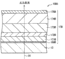
The structure of phosphor plates 10
Fig. 1 shows the cross-section structure of phosphor plates (color conversion sheet) 10 according to an embodiment of the invention.Phosphor plates 10 for example allows blue light to get into, and utilizes blue light to carry out colour switching as exciting light and white light is extracted making it possible to thus.Insert and put luminescent coating (colour switching layer) 11 through paired diaphragm seal 10A1 and 10B1 and obtain phosphor plates 10.Diaphragm seal 10A1 and 10B1 are attached to each other through adhesion layer 14.Through adhesion layer 14, luminescent coating 11 is sealed between diaphragm seal 10A1 and the 10B1.
It is desirable to, adhesion layer 14 is for example processed by UV cure adhesive, thermoset adhesive, tackifier or hot melt agent etc., and has the water vapor barrier properties.
Diaphragm seal 10A1 and 10B1 suppress water vapor and invade luminescent coating 11, and are arranged to it is being faced with each other when light incident side and light exit side insert and put luminescent coating 11.In the case, diaphragm seal 10A1 is set at light incident side, and diaphragm seal 10B1 is set at light exit side.Diaphragm seal 10A1 has the first inorganic stacked film 15A that obtains through (side relative with luminescent coating 11) range upon range of multilayer film of being processed by inorganic material on base material 12.Diaphragm seal 10B1 has and is positioned on the base material 13 the second inorganic stacked film 15B of (side relative with luminescent coating 11).The material of the film in first and second inorganic stacked film 15A and 15B and thickness etc. suitably are provided with to be presented at the predefined reflectivity characteristic that light incident side and light exit side differ from one another.The concrete structure of diaphragm seal 10A1 and 10B1 below will be described.
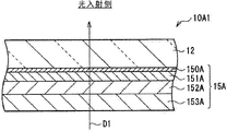
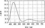
The stepped construction of diaphragm seal 10A1 (light incident side)
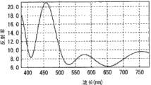
Fig. 2 A shows the section stepped construction of the diaphragm seal 10A1 that is positioned at light incident side, and Fig. 2 B then shows the reflectivity Characteristics for wavelength of diaphragm seal 10A1.Through on base material 12, stacking gradually such as monox (SiOx:1.5≤x≤1.7) film 150A, silicon nitride (SiN) film 151A, silicon dioxide (SiO as the first inorganic stacked film 15A
2) film 152A and SiN film 153A obtain diaphragm seal 10A1.In diaphragm seal 10A1, the direction from SiN film 153A to base material 12 is blue light transmission direction (D1), and blue light is from the lower surface entering of SiN film 153A.
Preferably, base material 12 has vapor barrier properties, and is processed by the material with the transparency, workability and heat impedance etc.The example of the material of base material 12 comprises such as polyethylene terephthalate (PET), polycarbonate (PC), polymethylmethacrylate (PMMA); Polystyrene (PS); PEN (PEN), polyethersulfone (PES) and circulation amorphous polyolefin, polyfunctional acrylic ester; Polyfunctional poly alkene, the thermoplastic resin of unsaturated polyester (UP) and epoxy resin etc.Particularly, more preferably use the degradation materials with smaller that causes because of blue LED, for example polyethylene terephthalate, polycarbonate, polymethylmethacrylate or polystyrene.
SiOx film 150A is configured to increase base material 12 and is formed on the tack between the inoranic membrane (in the case, SiN film 151A) on the SiOx film 150A, and it is processed by the monox that has oxygen defect.Preferably, the value of " x " is in the scope of 1.5 to 1.7 (comprising this two boundary values) among the SiOx film 150A.Reason is (will at following detailed description), if the value of " x " too small (for example, x<1.5), then light transmission reduces, on the other hand, if the value of " x " excessive (for example, x>1.7) then can not obtain good tack.SiN film 151A is as barrier layer, and it can suppress intrusion luminescent coatings 11 such as water vapor.
For example, the thickness of base material 12 is 100 μ m, and the thickness of SiOx film 150A is 2nm, and the thickness of SiN film 151A is 70nm, SiO
2The thickness of film 152A is 100nm, and the thickness of SiN film 153A is 100nm.
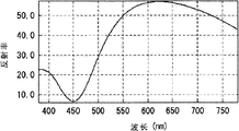
Through the first inorganic stacked film 15A, in diaphragm seal 10A1, show the for example reflectivity Characteristics shown in Fig. 2 B.Particularly, the reflectivity in green light (about 550nm) and the red light (about 650nm) is higher than the reflectivity in the blue light (about 450nm).In an embodiment, PET is used as base material 12.Usually, PET has about 10% reflectivity.Therefore, through the stepped construction of the first inorganic stacked film 15A, the light reflection in blue light is suppressed, and on the other hand, helps the light reflection in green and the red light.Particularly, the peak of light transmission is in about 420nm to 480nm, and the peak of reflectivity is in about 500nm to 680nm.
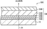
The stepped construction of diaphragm seal 10B1 (light exit side)
Fig. 3 A shows the stepped construction of analysing and observe of the diaphragm seal 10B1 that is positioned at light exit side, and Fig. 3 B shows the reflectivity Characteristics for wavelength of diaphragm seal 10B1.Through on base material 13, stacking gradually such as SiOx film 150B, SiN film 151B, SiO as the second inorganic stacked film 15B
2Film 152B, SiN film 153B and SiO
2Film 154B obtains diaphragm seal 10B1.In diaphragm seal 10B1, from base material 13 towards SiO
2The direction of film 154B is blue light transmission direction (D1), and from SiO
2The top surface of film 154B sends the white light as the mixing of blueness, green and red light.The materials similar of base material 12 among the material of base material 13 and the diaphragm seal 10A1.In the case, base material 13 is processed by PET.The function class of SiOx film 150A and SiOx film 151A seemingly among the function of SiOx film 150B and SiN film 151B and the diaphragm seal 10A1.
For example, the thickness of base material 13 is 100 μ m, and the thickness of SiOx film 150B is 2nm, and the thickness of SiN film 151B is 50nm, SiO
2The thickness of film 152B is 30nm, and the thickness of SiN film 153B is 200nm, and SiO
2The thickness of film 154B is 100nm.
Through the above-mentioned second inorganic stacked film 15B, in diaphragm seal 10B1, show the for example reflectivity Characteristics shown in Fig. 3 B.Particularly, the reflectivity of blue light is higher than the reflectivity of green and red light.In the present embodiment, the PET that has a reflectivity of about 10% is used as base material 13.Therefore,, help the light reflection of blue light, on the other hand, can suppress the light reflection of green and red light through the stepped construction of the second inorganic stacked film 15B.Particularly, the peak of reflectivity is in about 420nm to 480nm, and the peak of light transmission is in about 500nm to 680nm.
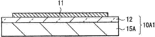
Make the method for phosphor plates 10
Phosphor plates 10 is for example processed as follows.At first, shown in Fig. 4 A, form diaphragm seal 10A1 through on base material 12, forming the first inorganic stacked film 15A.At this moment, on the base material of processing by above-mentioned material 12, for example through using methods such as reactive sputtering to come to form successively SiOx film 150A, SiN film 151A, SiO
2 Film 152A and SiN film 153A are to have above-mentioned thickness.Although not shown, with the similar mode of diaphragm seal 10A1, form diaphragm seal 10B1 through on base material 13, forming the second inorganic stacked film 15B.
Then, shown in Fig. 4 B, on the surface (being positioned at the surface of that side opposite) of the base material 12 of diaphragm seal 10A1, for example form the luminescent coating of processing by above-mentioned material 11 through serigraphy with the first inorganic stacked film 15A.At this moment, above-mentioned fluorophor and resin material are mixed into pasty state in solvent.For example use toluene, methyl ethyl ketone peroxide or terpinol etc. are as solvent.Above-mentioned paste is coated on the zone except that outer peripheral portion on surface of base material 12, and is dried.
Subsequently, shown in Fig. 4 C, the adhesion layer 14 that coating is processed by above-mentioned material covers the luminescent coating that formed 11 with base material 12 1 sides at diaphragm seal 10A1.
At last, diaphragm seal 10B1 is combined in and makes the base material 12 of diaphragm seal 10A1 and the base material 13 of diaphragm seal 10B1 face with each other on the adhesion layer 14.Thus, luminescent coating 11 is sealed between diaphragm seal 10A1 and the 10B1, accomplishes phosphor plates shown in Figure 1 10 thus.
The effect of phosphor plates 10 and effect
In phosphor plates 10, for example when blue light got into diaphragm seal 10A1, blue light passed first inorganic stacked film 15A and the base material 12 successively, and got into luminescent coating 11.A part that gets into the blue light of luminescent coating 11 is transformed to red light or green light in luminescent coating 11.When the green light and the red light that obtain through colour switching when passing luminescent coating 11 by the blue light of colour switching entering diaphragm seal 10B1; Light passes the base material 13 and the second inorganic stacked film 15B successively, and is extracted the white light that obtains as the mixing through three kinds of colors from the top of the second inorganic stacked film 15B.
Insert and put luminescent coating 11 through diaphragm seal 10A1 with first inorganic stacked film 15A and diaphragm seal 10B1, suppressed to invade luminescent coating 11 such as the gas of water vapor with second inorganic stacked film 15B.In an embodiment, particularly, SiN film 151A is arranged among the first inorganic stacked film 15A, and SiN film 151B is arranged among the second inorganic stacked film 15B, can suppress gas thus effectively and invade luminescent coating 11.
Shown in Fig. 2 B; Because it is high at the reflectivity of blue light at the luminance factor of red light and green light to be arranged in the diaphragm seal 10A1 of light incident side; So blue light is easier to pass the first inorganic stacked film 15A, on the other hand, red light and green light are easier to by the first inorganic stacked film 15A reflection.In other words, blue light is easier to get into luminescent coating 11, is easier to reflected to light exit side and in red light that is generated by luminescent coating 11 and green light, flee to the light of light incident side.
On the other hand; Shown in Fig. 3 B; Because the diaphragm seal 10B1 that is positioned at light exit side is higher than the reflectivity to red light and green light to the reflectivity of blue light; So red light and green light are easier to pass the second inorganic stacked film 15B, on the other hand, blue light is easier to by the second inorganic stacked film 15B reflection.In other words, red light and green light are easier to leave from the top of the second inorganic stacked film 15B.On the other hand, passing luminescent coating 11 is not easier to by second inorganic stacked film 15B reflection by the blue light of conversion and is back to luminescent coating 11 1 sides.
In addition, SiOx film 150A also is arranged between the SiN film 151A among the base material 12 and the first inorganic stacked film 15A, and SiOx film 150B also is arranged between the SiN film 151B among the base material 13 and the second inorganic stacked film 15B.Play the SiN film 151A of gas-barrier layer effect and the relatively poor defective of tack that 151B exists base material 12 and 13, and under hot and humid situation, be tending towards producing the crack.Be conceived to this, in the present embodiment, SiOx film 150A is arranged between the SiN film 151A among base material 12 and the diaphragm seal 10A1.Thus, improved the tack of SiN film 151A, and suppressed the generation of crack in SiN film 151A to base material 12.Diaphragm seal 10B1 and above similar.Therefore, the permanance of diaphragm seal 10A1 and 10B1 is improved.
Fig. 5 A shows the environmental testing result (that is, the SiN film is formed directly into the situation on the base material of being processed by PET) under the situation that does not form the SiOx film.On the other hand, Fig. 5 B shows the environmental testing result of under the situation that has formed the SiOx film between base material and the SiN film (that is present embodiment).Particularly, in high temperature (85 ℃) high humiditys (95%) environment, carried out above-mentioned environmental testing, the thickness of SiOx film is set to about 5mm, and the value of " x " is set to 1.5.Shown in Fig. 5 A, in the SiN film, generating the crack under the situation that does not form the SiOx film.On the contrary, shown in Fig. 5 B, under the situation that has formed the SiOx film, can generate the crack hardly.Therefore, think, can suppress the crack and in SiN film 151A and 151B, generate through utilizing SiOx film 150A and 150B that diaphragm seal 10A1 and 10B1 are set.
Based on following experimental result, when the value of " x " among SiOx film 150A and the 150B is in the scope of 1.5 to 1.7 (comprising this two boundary values), has kept sufficient light transmission, and obtained good adhesion base material.The value of on base material, having made " x " through reactive sputtering is in ten samples (sample 1 to 10) altogether in 0 to 2 the scope, and has measured the tack and the light transmission (%) of sample.Table 1 shows measurement result.Use argon gas (Ar) and oxygen (O
2) as sputter gas.As shown in table 1, through changing Ar and O
2Flow rate, the value of " x " is changed.Measure the value of " x " in each example through using the x-ray photoelectron spectroscopy.Other sputtering parameters are: power is set to 2.0kW, and thickness is set to 100nm to 200nm.
Table 1

As shown in table 1, when sputter, in the relatively low sample 1 to 6 (value of " x " is 1.7 or littler) of flow rate of oxygen, demonstrate splendid tack therein.But in the sample 1 to 3 in sample 1 to 6 (value of " x " is 1.2 or littler), light transmission is lower than 90%, and this is undesirable as far as optical component.Therefore, the value of " x " is preferably 1.5 to 1.7.In the case, in the optical loss in having suppressed SiOx film 150A and 150B, can obtain splendid tack.
As stated, in the present embodiment,, use blue light to extract white light as exciting light through luminescent coating 11.Because luminescent coating 11 is exposed to water vapor etc. by diaphragm seal 10A1 and 10B1 sealing so can prevent luminescent coating 11.Has different predetermined properties because be positioned at the reflectivity of the diaphragm seal 10A1 of light incident side with the reflectivity of the diaphragm seal 10B1 that is positioned at light exit side; So can in luminescent coating 11, obtain blue light effectively, and can extract green light and the red light that obtains through colour switching effectively as exciting light.Therefore, suppressed the deterioration of luminescent coating 11, and improved light extraction efficiency.In other words, utilize a small amount of fluorophor, realized effective light extraction of low waste.Because fluorescent material is comparatively expensive usually, so also can reduce cost.
Applying examples
As shown in Figure 6, phosphor plates 10 for example can be applicable to display device 1 (lighting device 3).
Display device 1 for example is LCD (LCD), and has the display panel 4 through directly over light source cell 2, arranging lighting device 3 that conduct that phosphor plates 10 obtains is backlight and coming show image based on image data.Between lighting device 3 and display panel 4, begin to be furnished with successively various optically functional films such as diffuser plate 5, diffusion barrier 6, lens coating 7 and reflective polarizing film 8 from lighting device 3 one sides.
In light source cell 2, a plurality of blue leds 21 with arranged at predetermined intervals on base material 20.Send blue light from each blue led 21 of light source cell 2 to phosphor plates 10.
For example obtain display panel 4 through sealing liquid crystal layer between TFT base material (being formed with pixel electrode and TFT (thin film transistor (TFT)) device etc. on it) and relative base material (being formed with (not shown these devices) such as comparative electrode and color filters on it).Light incident side and light exit side at display panel 4 are attached with the polarizer (not shown), make its polarization axle be perpendicular to one another.
Thereby diffuser plate 5 and diffusion barrier 6 are set make the intensity distributions homogeneous with the diffusion incident light.Through arranging that a plurality of prismatic projections obtain lens coating 7, and lens coating 7 has the function of assembling incident light.Reflective polarizing film 8 is set with one of transmission-polarizing light, and (towards lighting device 3 one sides) reflect other polarized lights so that light is reused downwards.Reflective polarizing film 8 is set to improve the light service efficiency.
In display device 1, the blue light that sends from blue led 21 is used as the exciting light of phosphor plates 10.Through using blue light,, promptly extracted white light from lighting device 3 from the top surface of phosphor plates 10.This white light is assembled by lens coating 7 by diffuser plate 5 and diffusion barrier 6 diffusions, passes reflective polarizing film 8, and is applied to display panel 4.The light that applies is in this way modulated based on image data by display panel 4, thus show image.
Change example of the present invention (changing example 1 to 3) will be described below.Following, utilize identical reference number represent with the foregoing description in similar assembly, and will save explanation to it.
In the above-described embodiments, as an example, use SiOx film, SiN film and SiO have been described
2Film is as the situation of the inorganic material film among first and second inorganic stacked film 15A and the 15B.But the inorganic material film that uses in the present invention is not limited to these films.For example,, substitute the SiN film, also aluminium oxide (Al can be set although formed the layer that the SiN film is used as having the gas barrier function in an embodiment
2O
3) film.In following change example 1 and 2, will describe and use Al
2O
3Film is as the concrete stepped construction of gas-barrier layer.In changing example 1 and 2, different with the stepped construction of the foregoing description in the stepped construction of the inorganic stacked film of each diaphragm seal that is arranged in light incident side and light exit side, therefore, the reflectivity Characteristics in the diaphragm seal differs from one another.Other structures are similar with the structure of the foregoing description.
Change example 1
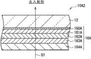
The stepped construction of diaphragm seal 10A2 (light incident side)
Fig. 7 A shows the stepped construction of analysing and observe according to the diaphragm seal 10A2 (light incident side) that changes example 1, and Fig. 7 B shows the reflectivity Characteristics for wavelength of diaphragm seal 10A2.Through on base material 12, stacking gradually such as SiOx film 150A, titania (TiO as the first inorganic layer lamination 16A
2) film 161A, Al
2O
3Film 162A, TiO
2Film 163A and Al
2O
3Film 164A obtains diaphragm seal 10A2.In diaphragm seal 10A2, from Al
2O
3Film 164A is blue light transmission direction (D1) to the direction of base material 12, and blue light is from Al
2O
3The lower surface of film 164A gets into.Change in the example at this, in diaphragm seal 10A2, Al
2O
3Film 162A plays the effect of the gas-barrier layer that suppresses intrusion luminescent coatings 11 such as water vapor.
The thickness of each inorganic material film is following.TiO
2The thickness of film 161A is 80.59nm, Al
2O
3The thickness of film 162A is 82.1nm, TiO
2The thickness of film 163A is 64.85nm, and Al
2O
3The thickness of film 164A is 92.59nm.Base material 12 (thickness is 100 μ m) and SiOx film 150A (thickness is 2nm) are similar to the above embodiments.
Through the above-mentioned first inorganic stacked film 16A, in diaphragm seal 10A2, for example demonstrate the reflectivity Characteristics shown in Fig. 7 B.Particularly, the reflectivity in green light and the red light is higher than the reflectivity in the blue light.In this changes example, with embodiment in the similar mode of diaphragm seal 10A1, through the stepped construction of the first inorganic stacked film 16A, the light reflection in the blue light is suppressed, and on the other hand, helps the light reflection in green and the red light.
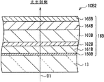
The stepped construction of diaphragm seal 10B2 (light exit side)
Fig. 8 A shows the stepped construction of analysing and observe of the diaphragm seal 10B2 that is positioned at light exit side, and Fig. 8 B shows the reflectivity Characteristics for wavelength of diaphragm seal 10B2.Through on base material 13, stacking gradually such as SiOx film 150B, Al as the second inorganic layer lamination 16B
2O
3Film 161B, TiO
2Film 162B, Al
2O
3Film 163B, TiO
2Film 164B and Al
2O
3Film 165B obtains diaphragm seal 10B2.In diaphragm seal 10B2, from base material 13 to Al
2O
3The direction of film 165B is blue light transmission direction (D1), and the white light of the mixing of conduct blueness, green and red light is from Al
2O
3The top surface of film 165B leaves.In diaphragm seal 10B2, Al
2O
3Film 161B works to suppress the gas-barrier layer that water vapor etc. is invaded luminescent coating 11.
The thickness of each inorganic material film is following.For example, Al
2O
3The thickness of film 161B is 100.31nm, TiO
2The thickness of film 162B is 69.53nm, Al
2O
3The thickness of film 163B is 202.45nm, TiO
2The thickness of film 164B is 141.27nm, and Al
2O
3The thickness of film 165B is 57.67nm.Base material 13 (thickness is 100 μ m) and SiOx film 150B (thickness is 2nm) are similar to the above embodiments.
Through the above-mentioned second inorganic stacked film 16B, in diaphragm seal 10B2, for example demonstrate the reflectivity Characteristics shown in Fig. 8 B.Particularly, the reflectivity in the blue light is higher than the reflectivity in green light and the red light.In this changes example, with embodiment in the similar mode of diaphragm seal 10B1, through the stepped construction of the second inorganic stacked film 16B, help the light reflection in the blue light, on the other hand, the light reflection in green and the red light is suppressed.
Change in the example at this; Diaphragm seal 10A2 and 10B2 have with the foregoing description in similar predefined reflectivity characteristic; In luminescent coating 11, obtained blue light thus effectively, on the other hand, extracted the green light and the red light that obtain through colour switching effectively as exciting light.Therefore, obtained effect similar to the above embodiments.In other words, first and second inorganic stacked film 16A and 16B can adopt and use Al
2O
3Film is as gas-barrier layer and use TiO
2The stepped construction of film.Although similar with the SiN film among the embodiment, Al
2O
3Film has the characteristic that under hot and humid situation, is tending towards generating the crack, but similar with embodiment, through at Al
2O
3The SiOx film is set as adhesion layer between film and the base material, can suppresses the generation in crack.
Change example 2
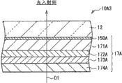
The stepped construction of diaphragm seal 10A3 (light incident side)
Fig. 9 A shows the stepped construction of analysing and observe according to the diaphragm seal 10A3 (light incident side) that changes example 2, and Fig. 9 B shows the reflectivity Characteristics for wavelength of diaphragm seal 10A3.Through on base material 12, stacking gradually such as SiOx film 150A, Al as the first inorganic layer lamination 17A
2O
3Film 171A, SiO
2Film 172A, Al
2O
3Film 173A and SiO
2Film 174A and obtain diaphragm seal 10A3.In diaphragm seal 10A3, from SiO
2Film 174A is blue light transmission direction (D1) to the direction of base material 12, and blue light is from SiO
2The lower surface of film 174A gets into.Change in the example at this, example 1 is similar with changing, in diaphragm seal 10A3, and Al
2O
3Film 171A plays the effect of the gas-barrier layer that suppresses intrusion luminescent coatings 11 such as water vapor.
The thickness of each inorganic material film is following.Al
2O
3The thickness of film 171A is 138.95nm, SiO
2The thickness of film 172A is 76.9nm, Al
2O
3The thickness of film 173A is 55.16nm, and SiO
2The thickness of film 174A is 103.31nm.Base material 12 (thickness is 100 μ m) and SiOx film 150A (thickness is 2nm) are similar to the above embodiments.
Through the above-mentioned first inorganic stacked film 17A, in diaphragm seal 10A3, for example demonstrate the reflectivity Characteristics shown in Fig. 9 B.Particularly, the reflectivity in green light and the red light is higher than the reflectivity in the blue light.In this changes example, with embodiment in the similar mode of diaphragm seal 10A1, through the stepped construction of the first inorganic stacked film 17A, the light reflection in the blue light is suppressed, and on the other hand, helps the light reflection in green and the red light.
The stepped construction of diaphragm seal 10B3 (light exit side)
Figure 10 A shows the stepped construction of analysing and observe of the diaphragm seal 10B3 that is positioned at light exit side, and Figure 10 B shows the reflectivity Characteristics for wavelength of diaphragm seal 10B3.Through on base material 13, stacking gradually such as SiOx film 150B, SiO as the second inorganic layer lamination 17B
2Film 171B, Al
2O
3Film 172B, SiO
2Film 173B, Al
2O
3Film 174B and SiO
2Film 175B obtains diaphragm seal 10B3.In diaphragm seal 10B3, from base material 13 to SiO
2The direction of film 175B is blue light transmission direction (D1), and the white light of the mixing of conduct blueness, green and red light is from SiO
2The top surface of film 175B leaves.In diaphragm seal 10B3, Al
2O
3Film 172B works to suppress the gas-barrier layer that water vapor etc. is invaded luminescent coating 11.
The thickness of each inorganic material film is following.For example, SiO
2The thickness of film 171B is 126.52nm.Al
2O
3The thickness of film 172B is 77.79nm, SiO
2The thickness of film 173B is 256.57nm, Al
2O
3The thickness of film 174B is 213.19nm, and SiO
2The thickness of film 175B is 67.52nm.Base material 13 (thickness is 100 μ m) and SiOx film 150B (thickness is 2nm) are similar to the above embodiments.
Through the above-mentioned second inorganic stacked film 17B, in diaphragm seal 10B3, for example demonstrate the reflectivity Characteristics shown in Figure 10 B.Particularly, the reflectivity in the blue light is higher than the reflectivity in green light and the red light.Equally in this changes example, with embodiment in the similar mode of diaphragm seal 10B1, through the stepped construction of the second inorganic stacked film 17B, help the light reflection in the blue light, on the other hand, the light reflection in green and the red light is suppressed.
Change in the example at this; Diaphragm seal 10A3 and 10B3 have with the foregoing description in similar predefined reflectivity characteristic; In luminescent coating 11, obtained blue light thus effectively, on the other hand, extracted the green light and the red light that obtain through colour switching effectively as exciting light.Therefore, obtained effect similar to the above embodiments.In other words, first and second inorganic stacked film 17A and 17B can adopt and use Al
2O
3Film is as gas-barrier layer and use SiO
2The stepped construction of film.
Change example 3
Figure 11 A and Figure 11 B show the cross-section structure according to the lighting device that changes example 3.The lighting device that changes example 3 use through make from the light of blue led 35 propagate and the luminous optical plate 34 of realization face as light source cell.Reflective optical system 34a and light diffuser 34B are arranged on the bottom surface of optical plate 34.Phosphor plates 10 is not limited to a plurality of blue leds and is arranged in the light source on the base material, but seemingly can combine with optical plate 34 with above-mentioned change example class.In the case, shown in Figure 11 A, be attached to the surface (light exit surface) of optical plate 34 light exit sides through making phosphor plates 10, the blue light that sends from the light exit surface of optical plate 34 is used as exciting light, thereby can extract white light.Perhaps,, blue light can be directly obtained, and the inside of optical plate 34 can be white light be issued to from blue led 35 through phosphor plates 10 being attached to the surface (side surface) of the light incident side of optical plate 34.In the case, also can phosphor plates 10 be applied to the backlight of use optical plate 34.
Although below described embodiments of the invention and changed example, the present invention is not limited to these embodiment etc., but can carry out various changes.For example, although in embodiment etc., described through using blue light to generate the situation of green light and red light as the colour switching of exciting light, the present invention is not limited to this situation.According to the type of fluorophor, can generate orange and yellow.The light that obtains from phosphor plates 10 is not limited to white light, and can be other color of light according to use and purpose.
In present embodiment etc., for each diaphragm seal of light incident side and light exit side all is provided with the silicon oxide film that has oxygen defect.But, also can not form silicon oxide film.As long as luminescent coating 11 is inserted and put by paired diaphragm seal and each diaphragm seal all has above-mentioned reflectivity Characteristics, just can obtain effect of the present invention.
In addition, in embodiment etc., although described the stepped construction of the inorganic stacked film in each diaphragm seal through concrete material and thickness, inorganic stacked film of the present invention is not limited to this.Also suitably set film thickness through range upon range of at least three inorganic material films, can realize above-mentioned reflectivity Characteristics.
In addition, in embodiment etc., more than described according to the handling procedure of so-called sheet feeding method (sheet-feedmethod) example as the handling procedure of making phosphor plates 10.But the present invention is not limited to this processing program.Also can use so-called roller to roller (roll-to-roll) handling procedure.In the case; By way of example, can be continuously or carry out in a lump through form the handling procedure of printing luminescent coating on handling procedure and the another side that inorganic stacked film forms diaphragm seal in order on the one side of sheet roll forming base material at base material.Subsequently, form otch and hope the phosphor plates of size and cutting blade with formation.Diaphragm seal is adhered to each other with the similar mode of above-mentioned handling procedure.
In embodiment etc., as an example, described through light source cell 2 and phosphor plates 10 and processed the arranged illumination devices mode.But the present invention is not limited to this set-up mode.For example, other optical functional layers such as diffuser plate 5, diffusion barrier 6, lens coating 7 and reflective polarizing film 8 etc. can also be set.In other words, comprise that light source cell and phosphor plates are just enough.
In addition, in embodiment etc., as an example, described and used the set-up mode of liquid crystal panel as the display panel of display device of the present invention.But the present invention is not limited to this set-up mode, but can be applied to other display device.
The application comprises the relevant theme that Japan of submitting to Jap.P. office with on March 23rd, 2009 is formerly disclosed among the patented claim JP 2009-070156, by reference its full content is combined in this manual.
It should be appreciated by those skilled in the art, drop under the prerequisite in accompanying claims scope or its equivalency range, can carry out these modifications, combination, son combination and replacement according to designing requirement and other factors in various modifications, combination, son combination and replacement.
Claims (19)
1. color conversion sheet comprises:
The colour switching layer, it will be transformed to second color of light with wavelength longer than the said first color light wavelength as the part of first color of light of incident light; And
Paired diaphragm seal, it inserts and puts said colour switching layer from light incident side and light exit side, and has the inorganic stacked film on that side opposite with said colour switching layer that is positioned at base material respectively,
Wherein, The said diaphragm seal that is positioned at said light incident side is higher than the reflectivity to said first color of light to the reflectivity of said second color of light; And the said diaphragm seal that is positioned at said light exit side is higher than the reflectivity to said second color of light to the reflectivity of said first color of light; The inorganic stacked film that is positioned at the said diaphragm seal on the light incident side is the first inorganic stacked film; And the inorganic stacked film that is positioned at the said diaphragm seal on the light exit side is the second inorganic stacked film, and the said first inorganic stacked film and the said second inorganic stacked film have silicon nitride (SiN) film that is positioned on the said base material respectively, and
Between said base material and said silicon nitride film, the said first inorganic stacked film and the said second inorganic stacked film have silicon oxide film SiOx:1.5≤x≤1.7 respectively, and do not have other films.
2. color conversion sheet according to claim 1, wherein,
The said first inorganic stacked film and the said second inorganic stacked film also have the silicon dioxide (SiO that is positioned on the said base material respectively
2) film.
3. color conversion sheet according to claim 2, wherein,
Obtain the said first inorganic stacked film through on said base material, stacking gradually said silicon oxide film SiOx, silicon nitride film, silicon dioxide film and silicon nitride film, and
Obtain the said second inorganic stacked film through on said base material, stacking gradually said silicon oxide film SiOx, silicon nitride film, silicon dioxide film, silicon nitride film and silicon dioxide film.
4. color conversion sheet comprises:
The colour switching layer, it will be transformed to second color of light with wavelength longer than the said first color light wavelength as the part of first color of light of incident light; And
Paired diaphragm seal, it inserts and puts said colour switching layer from light incident side and light exit side, and has the inorganic stacked film on that side opposite with said colour switching layer that is positioned at base material respectively,
Wherein, The said diaphragm seal that is positioned at said light incident side is higher than the reflectivity to said first color of light to the reflectivity of said second color of light; And the said diaphragm seal that is positioned at said light exit side is higher than the reflectivity to said second color of light to the reflectivity of said first color of light; The inorganic stacked film that is positioned at the said diaphragm seal on the light incident side is the first inorganic stacked film; And the inorganic stacked film that is positioned at the said diaphragm seal on the light exit side is the second inorganic stacked film, and the said first inorganic stacked film and the said second inorganic stacked film have the aluminium oxide (A1 that is positioned on the said base material respectively
2O
3) film, and
The said first inorganic stacked film and the said second inorganic stacked film have silicon oxide film SiOx:1.5≤x≤1.7 with said base material adjacent respectively.
5. color conversion sheet according to claim 4, wherein,
The said first inorganic stacked film and the said second inorganic stacked film also have the titania (TiO that is positioned on the said base material respectively
2) film.
6. color conversion sheet according to claim 5, wherein,
Obtain the said first inorganic stacked film through on said base material, stacking gradually said silicon oxide film SiOx, titanium dioxide film, pellumina, titanium dioxide film and pellumina, and
Obtain the said second inorganic stacked film through on said base material, stacking gradually said silicon oxide film SiOx, pellumina, titanium dioxide film, pellumina, titanium dioxide film and pellumina.
7. color conversion sheet according to claim 4, wherein,
The said first inorganic stacked film and the said second inorganic stacked film also have the silicon dioxide (SiO that is positioned on the said base material respectively
2) film.
8. color conversion sheet according to claim 7, wherein,
Obtain the said first inorganic stacked film through on said base material, stacking gradually said silicon oxide film SiOx, pellumina, silicon dioxide film, pellumina and silicon dioxide film, and
Obtain the said second inorganic stacked film through on said base material, stacking gradually said silicon oxide film SiOx, silicon dioxide film, pellumina, silicon dioxide film, pellumina and silicon dioxide film.
9. according to claim 1 or 4 described color conversion sheets, wherein,
Said first color of light is a blue light.
10. color conversion sheet according to claim 9, wherein,
White light shines said light exit side.
11. a lighting device comprises:
Color conversion sheet; And
Light source cell, it sends first color of light to said color conversion sheet,
Wherein, said color conversion sheet comprises
Colour switching layer, its part with said first color of light are transformed to second color of light with wavelength longer than the said first color light wavelength; And
Paired diaphragm seal, it inserts and puts said colour switching layer from light incident side and light exit side, and has the inorganic stacked film on that side opposite with said colour switching layer that is positioned at base material respectively, and
The said diaphragm seal that is positioned at said light incident side is higher than the reflectivity to said first color of light to the reflectivity of said second color of light; And the said diaphragm seal that is positioned at said light exit side is higher than the reflectivity to said second color of light to the reflectivity of said first color of light
Wherein, The inorganic stacked film that is positioned at the said diaphragm seal on the light incident side is the first inorganic stacked film; And the inorganic stacked film that is positioned at the said diaphragm seal on the light exit side is the second inorganic stacked film; The said first inorganic stacked film and the said second inorganic stacked film have silicon nitride (SiN) film that is positioned on the said base material respectively, and
Between said base material and said silicon nitride film, the said first inorganic stacked film and the said second inorganic stacked film have silicon oxide film SiOx:1.5≤x≤1.7 respectively, and do not have other films.
12. a lighting device comprises:
Color conversion sheet; And
Light source cell, it sends first color of light to said color conversion sheet,
Wherein, said color conversion sheet comprises
Colour switching layer, its part with said first color of light are transformed to second color of light with wavelength longer than the said first color light wavelength; And
Paired diaphragm seal, it inserts and puts said colour switching layer from light incident side and light exit side, and has the inorganic stacked film on that side opposite with said colour switching layer that is positioned at base material respectively, and
The said diaphragm seal that is positioned at said light incident side is higher than the reflectivity to said first color of light to the reflectivity of said second color of light; And the said diaphragm seal that is positioned at said light exit side is higher than the reflectivity to said second color of light to the reflectivity of said first color of light
Wherein, The inorganic stacked film that is positioned at the said diaphragm seal on the light incident side is the first inorganic stacked film; And the inorganic stacked film that is positioned at the said diaphragm seal on the light exit side is the second inorganic stacked film, and the said first inorganic stacked film and the said second inorganic stacked film have the aluminium oxide (Al that is positioned on the said base material respectively
2O
3) film, and
The said first inorganic stacked film and the said second inorganic stacked film have silicon oxide film SiOx:1.5≤x≤1.7 with said base material adjacent respectively, and do not have other films.
13. according to claim 11 or 12 described lighting devices, wherein,
Said light source cell is formed by a plurality of light emitting diodes, and said a plurality of light emitting diodes are arranged in the plane parallel with said color conversion sheet.
14. according to claim 11 or 12 described lighting devices, wherein said light source cell comprises:
Optical plate, it has the light-emitting area parallel with said color conversion sheet; And
Light emitting diode, it sends first color of light to said optical plate inside.
15. according to claim 11 or 12 described lighting devices, wherein,
Said first color of light is a blue light.
16. lighting device according to claim 15, wherein,
White light shines said light exit side.
17. a display device comprises:
The display panel of show image;
Send the light source cell of first color of light; And
Color conversion sheet, it is arranged between said display panel and the said light source cell,
Wherein, said color conversion sheet comprises
Colour switching layer, its part with said first color of light are transformed to second color of light with wavelength longer than the said first color light wavelength; And
Paired diaphragm seal, it inserts and puts said colour switching layer from light incident side and light exit side, and has the inorganic stacked film on that side opposite with said colour switching layer that is positioned at base material respectively, and
The said diaphragm seal that is positioned at said light incident side is higher than the reflectivity to said first color of light to the reflectivity of said second color of light; And the said diaphragm seal that is positioned at said light exit side is higher than the reflectivity to said second color of light to the reflectivity of said first color of light
Wherein, The inorganic stacked film that is positioned at the said diaphragm seal on the light incident side is the first inorganic stacked film; And the inorganic stacked film that is positioned at the said diaphragm seal on the light exit side is the second inorganic stacked film; The said first inorganic stacked film and the said second inorganic stacked film have silicon nitride (SiN) film that is positioned on the said base material respectively, and
Between said base material and said silicon nitride film, the said first inorganic stacked film and the said second inorganic stacked film have silicon oxide film SiOx:1.5≤x≤1.7 respectively, and do not have other films.
18. a display device comprises:
The display panel of show image;
Send the light source cell of first color of light; And
Color conversion sheet, it is arranged between said display panel and the said light source cell,
Wherein, said color conversion sheet comprises
Colour switching layer, its part with said first color of light are transformed to second color of light with wavelength longer than the said first color light wavelength; And
Paired diaphragm seal, it inserts and puts said colour switching layer from light incident side and light exit side, and has the inorganic stacked film on that side opposite with said colour switching layer that is positioned at base material respectively, and
The said diaphragm seal that is positioned at said light incident side is higher than the reflectivity to said first color of light to the reflectivity of said second color of light; And the said diaphragm seal that is positioned at said light exit side is higher than the reflectivity to said second color of light to the reflectivity of said first color of light
Wherein, The inorganic stacked film that is positioned at the said diaphragm seal on the light incident side is the first inorganic stacked film; And the inorganic stacked film that is positioned at the said diaphragm seal on the light exit side is the second inorganic stacked film, and the said first inorganic stacked film and the said second inorganic stacked film have the aluminium oxide (Al that is positioned on the said base material respectively
2O
3) film, and
The said first inorganic stacked film and the said second inorganic stacked film have silicon oxide film SiOx:1.5≤x≤1.7 with said base material adjacent respectively, and do not have other films.
19. according to claim 17 or 18 described display device, wherein,
Said first color of light is a blue light, and
White light shines said light exit side.
Applications Claiming Priority (2)
| Application Number | Priority Date | Filing Date | Title |
|---|---|---|---|
| JP2009-070156 | 2009-03-23 | ||
| JP2009070156A JP2010225373A (en) | 2009-03-23 | 2009-03-23 | Color conversion sheet, illumination device, and display device |
Publications (2)
| Publication Number | Publication Date |
|---|---|
| CN101846849A CN101846849A (en) | 2010-09-29 |
| CN101846849B true CN101846849B (en) | 2012-07-04 |
Family
ID=42737261
Family Applications (1)
| Application Number | Title | Priority Date | Filing Date |
|---|---|---|---|
| CN2010101345468A Expired - Fee Related CN101846849B (en) | 2009-03-23 | 2010-03-16 | Color conversion sheet, illumination device, and display device |
Country Status (4)
| Country | Link |
|---|---|
| US (1) | US8451402B2 (en) |
| JP (1) | JP2010225373A (en) |
| CN (1) | CN101846849B (en) |
| TW (1) | TW201040588A (en) |
Families Citing this family (39)
| Publication number | Priority date | Publication date | Assignee | Title |
|---|---|---|---|---|
| KR101791580B1 (en) | 2009-10-17 | 2017-10-30 | 삼성전자주식회사 | An optical component, products including same, and methods for making same |
| WO2012061985A1 (en) * | 2010-11-10 | 2012-05-18 | Chang Kuo-Kuang | Method for manufacturing cover plate and method for manufacturing encapsulated light-emitting diode using the cover plate |
| US8888348B2 (en) * | 2011-04-08 | 2014-11-18 | Sharp Kabushiki Kaisha | Lighting device, display device and television receiver |
| KR101210180B1 (en) | 2011-04-21 | 2012-12-07 | 엘지이노텍 주식회사 | Optical member and method for fabricating the same |
| TWI649404B (en) | 2011-07-05 | 2019-02-01 | 迪睿合股份有限公司 | Resin composition for forming a phosphor sheet |
| KR20140035978A (en) | 2011-07-05 | 2014-03-24 | 데쿠세리아루즈 가부시키가이샤 | Resin composition for forming fluorescent sheet |
| KR101936116B1 (en) * | 2011-07-14 | 2019-01-10 | 엘지이노텍 주식회사 | Optical member, display device having the same and method for fabricating the same |
| KR20130022060A (en) * | 2011-08-24 | 2013-03-06 | 삼성디스플레이 주식회사 | Backlight assembly and method of manufacturing the same |
| WO2013035485A1 (en) * | 2011-09-05 | 2013-03-14 | 日本電気硝子株式会社 | Light emitting device cell, light emitting device, and light emitting device cell manufacturing method |
| KR101843466B1 (en) * | 2011-11-30 | 2018-05-14 | 엘지이노텍 주식회사 | Optical member and display device |
| JP5915309B2 (en) * | 2012-03-26 | 2016-05-11 | 大日本印刷株式会社 | Backlight device and liquid crystal display device using the same |
| JP5952636B2 (en) * | 2012-05-10 | 2016-07-13 | 日東光学株式会社 | Color temperature changing filter and optical module having color temperature changing filter |
| JP2015158523A (en) * | 2012-06-07 | 2015-09-03 | シャープ株式会社 | display device |
| CN103511871A (en) * | 2012-06-29 | 2014-01-15 | 展晶科技(深圳)有限公司 | Light-emitting diode lamp |
| KR101658396B1 (en) | 2013-03-21 | 2016-09-21 | 엘지디스플레이 주식회사 | Display device |
| JP5796038B2 (en) | 2013-06-18 | 2015-10-21 | デクセリアルズ株式会社 | Phosphor sheet |
| JP6217187B2 (en) * | 2013-07-03 | 2017-10-25 | ソニー株式会社 | Light emitting device and display device |
| EP3033552B1 (en) | 2013-08-16 | 2023-05-31 | Samsung Electronics Co., Ltd. | Methods for making optical components and products including same |
| EP2871408A1 (en) * | 2013-11-11 | 2015-05-13 | LG Display Co., Ltd. | Backlight unit and display device including the same |
| JP5820894B2 (en) * | 2014-02-21 | 2015-11-24 | デクセリアルズ株式会社 | Sealing tape, phosphor sheet, and method for producing phosphor sheet |
| KR101555954B1 (en) * | 2014-04-01 | 2015-09-30 | 코닝정밀소재 주식회사 | Substrate for color conversion of led and method of fabricating threof |
| WO2015152396A1 (en) * | 2014-04-04 | 2015-10-08 | 凸版印刷株式会社 | Wavelength conversion sheet, backlight unit, and film for protecting luminescent substance |
| KR102204953B1 (en) * | 2014-06-25 | 2021-01-19 | 삼성디스플레이 주식회사 | Fluorescent sheet and light unit and liquid crystal display including the same |
| KR102227197B1 (en) * | 2014-10-24 | 2021-03-12 | 엘지디스플레이 주식회사 | Liquid crystal display device |
| JP2016096276A (en) * | 2014-11-14 | 2016-05-26 | 富士フイルム株式会社 | Wavelength conversion member and backlight unit having the same, liquid crystal display device, and method for manufacturing wavelength conversion member |
| KR102230594B1 (en) * | 2014-12-26 | 2021-03-22 | 엔에스 마테리얼스 아이엔씨. | Wavelength conversion member and method for manufacturing same |
| KR20160094887A (en) * | 2015-01-31 | 2016-08-10 | 주식회사 엘지화학 | Light conversion device and display apparatus comprising the same |
| JP7000156B2 (en) | 2015-09-07 | 2022-02-04 | 凸版印刷株式会社 | Protective film for wavelength conversion sheet, wavelength conversion sheet and backlight unit |
| CN105093664B (en) * | 2015-09-22 | 2018-03-02 | 京东方科技集团股份有限公司 | Backlight module and display device |
| KR102148058B1 (en) | 2015-09-25 | 2020-08-26 | 주식회사 엘지화학 | Compound containing nitrogen and color conversion film comprising the same |
| JP6092446B1 (en) * | 2015-10-23 | 2017-03-08 | デクセリアルズ株式会社 | Partially driven light source device and image display device using the same |
| TWI582520B (en) | 2015-12-18 | 2017-05-11 | 中強光電股份有限公司 | Wavelength conversion device and projector |
| CN107544178A (en) * | 2016-06-29 | 2018-01-05 | 株式会社Lg化学 | Light conversion element and the display device for including it |
| US10955607B2 (en) * | 2017-03-07 | 2021-03-23 | Lumileds Llc | LED lighting device with remote phosphor in-coupling structure for in-coupling light from light emitting diodes |
| JP2017140439A (en) * | 2017-04-12 | 2017-08-17 | セイコーエプソン株式会社 | Pulse wave measuring module and electronic device |
| CN106873253A (en) * | 2017-04-19 | 2017-06-20 | 京东方科技集团股份有限公司 | A kind of display panel and liquid crystal display device |
| KR101986005B1 (en) * | 2017-04-26 | 2019-06-04 | 도레이첨단소재 주식회사 | Color change sheet and backlight unit including the same |
| TWI613804B (en) * | 2017-09-04 | 2018-02-01 | 友達光電股份有限公司 | Light detector |
| US11143929B2 (en) | 2018-03-09 | 2021-10-12 | E Ink Corporation | Reflective electrophoretic displays including photo-luminescent material and color filter arrays |
Family Cites Families (16)
| Publication number | Priority date | Publication date | Assignee | Title |
|---|---|---|---|---|
| US4822144A (en) * | 1986-12-24 | 1989-04-18 | U.S. Philips Corporation | Electro-optic color display including luminescent layer and interference filter |
| CA2120877A1 (en) * | 1993-04-28 | 1994-10-29 | Jesse D. Wolfe | Durable first and second surface mirrors |
| JP2004341541A (en) * | 1994-02-15 | 2004-12-02 | Dainippon Printing Co Ltd | Optical functional membrane, optical functional film, antiglare- antireflection film, manufacturing method therefor, polarizing plate, and liquid crystal display device |
| JP3966954B2 (en) * | 1997-09-01 | 2007-08-29 | 東芝電子エンジニアリング株式会社 | Illumination device, reading device, projection device, purification device, and display device |
| US6172810B1 (en) * | 1999-02-26 | 2001-01-09 | 3M Innovative Properties Company | Retroreflective articles having polymer multilayer reflective coatings |
| JP4068993B2 (en) * | 2003-02-26 | 2008-03-26 | 帝人デュポンフィルム株式会社 | Transparent conductive laminated film |
| JP2004352928A (en) | 2003-05-30 | 2004-12-16 | Mitsubishi Chemicals Corp | Light emitting equipment and lighting unit |
| JP4461759B2 (en) | 2003-09-30 | 2010-05-12 | ソニー株式会社 | Surface light emitting device and liquid crystal display device |
| JP2006049657A (en) | 2004-08-06 | 2006-02-16 | Citizen Electronics Co Ltd | Led lamp |
| JP4837271B2 (en) * | 2004-10-04 | 2011-12-14 | 株式会社アルバック | Method for forming antireflection film |
| JP2006163939A (en) | 2004-12-08 | 2006-06-22 | Nec Corp | System, method and terminal program for supporting taxi company operation |
| CN1928593A (en) * | 2005-09-07 | 2007-03-14 | 住友化学株式会社 | Highly durable polarization plate and liquid crystal display |
| US7839072B2 (en) * | 2006-05-24 | 2010-11-23 | Citizen Electronics Co., Ltd. | Translucent laminate sheet and light-emitting device using the translucent laminate sheet |
| CN100502065C (en) * | 2006-10-09 | 2009-06-17 | 李屹 | High-efficiency fluorescent converted LED light source and backlight module |
| WO2008149874A1 (en) * | 2007-06-08 | 2008-12-11 | Semiconductor Energy Laboratory Co., Ltd. | Display device |
| US8456082B2 (en) * | 2008-12-01 | 2013-06-04 | Ifire Ip Corporation | Surface-emission light source with uniform illumination |
-
2009
- 2009-03-23 JP JP2009070156A patent/JP2010225373A/en active Pending
-
2010
- 2010-02-23 TW TW099105190A patent/TW201040588A/en unknown
- 2010-03-08 US US12/719,383 patent/US8451402B2/en active Active
- 2010-03-16 CN CN2010101345468A patent/CN101846849B/en not_active Expired - Fee Related
Also Published As
| Publication number | Publication date |
|---|---|
| TW201040588A (en) | 2010-11-16 |
| JP2010225373A (en) | 2010-10-07 |
| US8451402B2 (en) | 2013-05-28 |
| CN101846849A (en) | 2010-09-29 |
| US20100238381A1 (en) | 2010-09-23 |
Similar Documents
| Publication | Publication Date | Title |
|---|---|---|
| CN101846849B (en) | Color conversion sheet, illumination device, and display device | |
| KR101760225B1 (en) | Protective film for wavelength conversion sheet, wavelength conversion sheet and backlight unit | |
| JP5717949B2 (en) | Optical member and display device | |
| CN106133562B (en) | Wavelength conversion sheet, backlight unit, and protective film for phosphor | |
| CN101943374B (en) | Phosphor sheet, a diffusion plate, an illuminating device, and a display unit | |
| CN102016403B (en) | Light-emitting device, display device, and color conversion sheet | |
| CN101451673B (en) | Illumination apparatus, color conversion device, and display apparatus | |
| CN106195923A (en) | Light conversion film and there is back light unit and the display device of described smooth conversion film | |
| CN105793644A (en) | Quantum dot protective film, quantum dot film using same, and backlight unit | |
| CN1836019A (en) | Double-sided pressure-sensitive adhesive sheet | |
| KR20140035979A (en) | Resin composition for forming fluorescent sheet | |
| KR101779606B1 (en) | one body optical transforming sheet, backlight unit and liquid crystal display device module having the same | |
| CN108803141A (en) | Quantum dot integrates optical module, backlight module and liquid crystal display | |
| JP2016194552A (en) | Quantum dot sheet, backlight device, display, and manufacturing method of quantum dot sheet | |
| US10663642B2 (en) | Backlight unit, display apparatus including the same and method of manufacturing the same | |
| JP2016062804A (en) | Luminaire and display device using wavelength conversion sheet | |
| JP2016194996A (en) | Backlight device and display device | |
| KR20180007870A (en) | Color conversion film integrated with polarizing plate and display apparatus comprising the same | |
| US7808583B2 (en) | Polarizing sheet capable of color conversion and liquid crystal display equipped with the polarizing sheet | |
| JP2016194561A (en) | Quantum dot sheet, backlight device, and display | |
| JP2009224245A (en) | Light emitting fixture and liquid crystal display device | |
| KR102054274B1 (en) | Quantum dot optical sheet, back light unit comprising the same and display apparatus | |
| JP2021009807A (en) | Backlight module and display device | |
| KR20180056563A (en) | Liquid Crystal Display Device Comprising High Brightness Film | |
| KR20180056566A (en) | liquid crystal display device for improving brightness and composite sheet for liquid crystal display |
Legal Events
| Date | Code | Title | Description |
|---|---|---|---|
| C06 | Publication | ||
| PB01 | Publication | ||
| C10 | Entry into substantive examination | ||
| SE01 | Entry into force of request for substantive examination | ||
| C14 | Grant of patent or utility model | ||
| GR01 | Patent grant | ||
| CF01 | Termination of patent right due to non-payment of annual fee | ||
| CF01 | Termination of patent right due to non-payment of annual fee |
Granted publication date: 20120704 |