CN101825265B - LED track lamp - Google Patents
LED track lamp Download PDFInfo
- Publication number
- CN101825265B CN101825265B CN 201010132774 CN201010132774A CN101825265B CN 101825265 B CN101825265 B CN 101825265B CN 201010132774 CN201010132774 CN 201010132774 CN 201010132774 A CN201010132774 A CN 201010132774A CN 101825265 B CN101825265 B CN 101825265B
- Authority
- CN
- China
- Prior art keywords
- lamp
- track
- led
- conductive plate
- positive
- Prior art date
- Legal status (The legal status is an assumption and is not a legal conclusion. Google has not performed a legal analysis and makes no representation as to the accuracy of the status listed.)
- Expired - Fee Related
Links
- 238000003780 insertion Methods 0.000 claims description 15
- 230000037431 insertion Effects 0.000 claims description 15
- 238000009413 insulation Methods 0.000 claims description 13
- NJPPVKZQTLUDBO-UHFFFAOYSA-N novaluron Chemical compound C1=C(Cl)C(OC(F)(F)C(OC(F)(F)F)F)=CC=C1NC(=O)NC(=O)C1=C(F)C=CC=C1F NJPPVKZQTLUDBO-UHFFFAOYSA-N 0.000 claims description 12
- 230000000295 complement effect Effects 0.000 claims description 6
- 239000007769 metal material Substances 0.000 claims description 3
- 238000012423 maintenance Methods 0.000 abstract description 3
- 238000004519 manufacturing process Methods 0.000 abstract 1
- 238000000354 decomposition reaction Methods 0.000 description 6
- 238000005516 engineering process Methods 0.000 description 4
- 230000008878 coupling Effects 0.000 description 3
- 238000010168 coupling process Methods 0.000 description 3
- 238000005859 coupling reaction Methods 0.000 description 3
- 230000003321 amplification Effects 0.000 description 2
- 238000003199 nucleic acid amplification method Methods 0.000 description 2
- 230000009286 beneficial effect Effects 0.000 description 1
- 230000005540 biological transmission Effects 0.000 description 1
- 230000002950 deficient Effects 0.000 description 1
- 238000010586 diagram Methods 0.000 description 1
- 230000000694 effects Effects 0.000 description 1
- 238000004134 energy conservation Methods 0.000 description 1
- 230000002401 inhibitory effect Effects 0.000 description 1
- 238000009434 installation Methods 0.000 description 1
- 230000004048 modification Effects 0.000 description 1
- 238000012986 modification Methods 0.000 description 1
- 230000005855 radiation Effects 0.000 description 1
- 230000001105 regulatory effect Effects 0.000 description 1
Images





Landscapes
- Fastening Of Light Sources Or Lamp Holders (AREA)
Abstract
The invention discloses an LED track lamp, which comprises a track and a plurality of LED lamps connected with the track, wherein the track comprises a guide rail and positive and negative conductive plates which are arranged in the guide rail at an interval; the LED lamp comprises a lamp holder and a lamp cap; the lamp holder is provided with a clamping slot matched with the guide rail; the two sides of the clamping slot are provided with a symmetric mounting hole respectively; the track is clamped in the clamping slot of the lamp holder; positive and negative conducting strips which are in electrical contact with the positive and negative conductive plates and extend into the mounting holes are correspondingly arranged in the lamp holder; each mounting hole comprises an inserting part and a locking part which are communicated with each other; the lamp cap is provided with two T-shaped electrical buckles corresponding to the mounting holes; the T-shaped heads of the T-shaped electrical buckles are inserted from the inserting parts of the mounting holes and turned to the locking parts to be locked tightly and are in electrical contact with the positive and negative conducting strips respectively. The LED track lamp has the advantages of simple structure, convenient manufacturing and maintenance and light and compact overall structure.
Description
[technical field]
The present invention relates to a kind of illuminating light fixture, particularly relating to a kind of is light source with LED, the track lamp that can move along planned orbit.
[background technology]
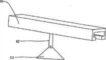
The track lamp be a kind of be used in shop and exhibition center etc. need be to the light fixture of commodity or show piece emphasis light projector; Its structure comprises sliding rail and the shot-light that can regulate the fixed position along sliding rail; Its advantage is can be according to the transmission direction of the putting position of article adjustment shot-light, reaches with effect the most clearly to show article.And LED track lamp promptly is to use the light source of LED as shot-light, and this track lamp has combined advantages such as the luminous thermal discharge of LED is few, radiation is little, and the energy-conservation and life-span is long, is particularly suitable for applying in temperature-sensitive or age inhibiting commodity of needs or the showpiece.In the prior art, the design of LED track lamp is generally shown in figure 16, comprises the track 01 of a built-in chute, can be in chute direction along ng a path regulate the fixed position lamp stand 02 and with lamp stand 02 hinged LED shot-light 03.Because the track of this LED track lamp need be provided with chute and lead is set in chute in a housing, so its overall structure is thick and heavy, make relatively difficulty, part is more at random, and globality is not strong.
The oriented before this State Patent Office of the applicant has submitted a utility application; This patent announcement number is CN201059503Y, and this utility model patent discloses a kind of low-voltage LED track lamp, comprises the two parallel guide rods that serve as guide rail and conduction double action; Both sides are extended with and hang arm and be across two positioning seats that walk abreast and removably be electrically connected with guide rod between the guide rods through this extensions arm; With the LED shot-light that hangs on through universal joint on the positioning seat, the LED shot-light can three-dimensionally be regulated projecting direction, and is shown in figure 17; The function of guide rail and positioning seat existing structure has the function of conduction again, has the advantage light and handy, that parts are few, globality is strong.Because two guide rods of above-mentioned LED track lamp are to be used for guide rail and conduction double action; Said two guide rods are to be exposed to LED track lamp outside; Can only be applicable on the Low voltage lamp; So this LED track lamp exists that brightness is low, range of exposures is little, can't satisfy the defectives such as use of household and commercial lighting, at present, suddenly need the technical problem that a kind of high brightness and the high LED track lamp of safety coefficient avoid above-mentioned conventional rails lamp to exist.
[summary of the invention]
The technical problem that the present invention will solve provide a kind of simple in structure, make easy to maintenance, whole light and handy compact, range of exposures is wide and high brightness and the high LED track lamp of safety coefficient.
In order to solve the problems of the technologies described above; The technical scheme that the present invention adopts is: a kind of LED track lamp; The a plurality of LED lamps that comprise track and be connected with said track is characterized in that, the positive and negative electrode conductive plate that said track comprises guide rail and in said guide rail, is provided with at interval; Said LED lamp comprises lamp socket and lamp holder; Said lamp socket be provided with one with the draw-in groove of said guide rail; Be provided with the installing hole of a symmetry in the both sides of said draw-in groove; Said track is stuck in the draw-in groove of lamp socket, and correspondence is provided with the positive and negative electrode conducting strip that electrically contacts and extend to installing hole with said positive and negative electrode conductive plate in lamp socket, and said installing hole comprises the insertion section and the sticking department of mutual perforation; Said lamp holder is provided with two " T " shapes corresponding with said installing hole conductions and buckle, and " T " shape head of said " T " shape conduction button inserts from the insertion section of said installing hole and rotates to sticking department and lock and electrically contact with said positive and negative electrode conducting strip respectively.
The invention has the beneficial effects as follows: owing in traditional guide rail, be equipped with the positive and negative electrode conductive plate at interval; A plurality of LED lamps are connected on the said track; Said LED lamp comprises lamp socket and lamp holder; Said lamp socket be provided with one with the draw-in groove of said guide rail; Be provided with the installing hole of a symmetry in the both sides of said draw-in groove, said track is stuck in the draw-in groove of lamp socket, the corresponding positive and negative electrode conducting strip that electrically contacts and extend to installing hole with said positive and negative electrode conductive plate that is provided with in lamp socket; Said lamp holder is provided with two " T " shapes corresponding with said installing hole conductions and buckle, and " T " shape head of said " T " shape conduction button inserts from the insertion section of said installing hole and rotates to that sticking department is locked and said respectively positive and negative electrode conducting strip electrically contacts.That the present invention has is simple in structure, make the advantage of easy to maintenance and whole light and handy compactness; Because the positive and negative electrode conductive plate is to be embedded in the guide rail; Go for the high pressure rail light fixture; The present invention has the safety coefficient height, and its brightness and range of exposures can satisfy the characteristics of lighting of home and commercial lighting use.
Preferably, said insertion section is a circular hole, and said sticking department is the elongated hole of width less than Circularhole diameter, and said " T " shape head is a T shape cylinder.
Preferably, two elongated holes that said insertion section and sticking department are arranged for " fourth " word, said " T " shape head are one " T " shape frame.
Preferably, said lamp socket is to be fixed on the said guide rail through positioning seat.
Preferably, between said lamp socket and lamp holder, also be provided with a lamp housing, said lamp housing is provided with the bayonet socket that is complementary with said track cross-section, and said lamp housing is fixed between said lamp socket and the lamp holder, and the bayonet socket of said lamp housing buckles on said guide rail.
Preferably, in said guide rail, also be provided with the conductive plate of a ground connection, the conductive plate of said ground connection is arranged between the positive and negative electrode conductive plate at interval, the corresponding conducting strip that contacts with the conductive plate of said ground connection that is provided with in said lamp socket.
Preferably; Said guide rail is that metal material is made; Between the conductive plate of said guide rail and positive and negative electrode conductive plate and ground connection, be provided with insulation strip, the conductive plate of said positive and negative conductive plate and ground connection is embedded in the said insulation strip, and said insulation strip is embedded in the said guide rail.
Preferably, at an end of said track the power connection that is connected with external power source is installed, said power connection is fixed on the said track, in said power connection, is provided with the electroconductive elastic sheet with the corresponding contact of conductive plate of said positive and negative electrode conductive plate and ground connection.
Preferably; Said lamp holder comprises connector, be installed in conduction on the connector buckles, is arranged on power-supply controller of electric in the connector, is fixed on the connector power-supply controller of electric is contained in the pedestal in the connector, the lampshade that is installed in the LED lamp plate on the pedestal and is fixed on LED lamp plate front end; Said power-supply controller of electric and said conduction buckle, said LED lamp plate is connected with said power-supply controller of electric.
Preferably, said LED lamp plate comprises circuit board and plurality of LEDs bulb, and said LED bulb is welded on the said circuit board.
[description of drawings]
Below in conjunction with accompanying drawing the present invention is done further explain.
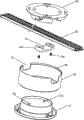
Fig. 1 is the decomposition texture sketch map of LED lamp of the present invention and track.
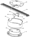
Fig. 2 is the decomposition texture sketch map of another angle of LED lamp of the present invention and track.
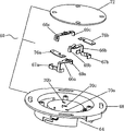
Fig. 3 is the decomposition texture sketch map of lamp holder of the present invention.
Fig. 4 is the decomposition texture sketch map of lamp socket of the present invention.
Fig. 5 is the structural representation of pedestal of the present invention shown in Figure 4.
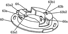
Another embodiment that Fig. 6 buckles for the conduction of the installing hole of lamp socket of the present invention and lamp holder.
Fig. 7 is the structural representation of another angle of lamp socket shown in Figure 6.
Fig. 8 is the decomposition texture sketch map of track of the present invention.
Fig. 9 is the assembly structure figure of LED lamp of the present invention and track.
Figure 10 is the amplification right view of Fig. 9.
Figure 11 is the local enlarged diagram of A part shown in Figure 10.
Figure 12 is the amplification three-dimensional cutaway view figure of Fig. 9.
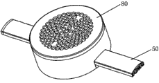
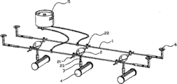
Figure 13 is the structural representation of LED track lamp of the present invention.
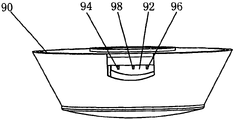
Figure 14 is the structural representation of power connection of the present invention.
Figure 15 is the decomposition texture sketch map of power connection shown in Figure 14.
Figure 16 is the structural representation of first kind of technical scheme of background technology of the present invention.
Figure 17 is the structural representation of second kind of technical scheme of background technology of the present invention.
[specific embodiment]
Shown in accompanying drawing 1-5 and 8-13; The a plurality of LED lamps 80 that the present invention includes track 50 and be connected with said track 50; Positive and negative electrode conductive plate 52a, 52b that said track 50 comprises guide rail 56 and in said guide rail 56, is provided with at interval, said conductive plate 52a, 52b extend along the length direction of guide rail 56; Said LED lamp 80 comprises lamp socket 60 and lamp holder 10; Said lamp socket 60 be provided with one with the draw-in groove 64 of said guide rail 56 couplings; Be provided with installing hole 62a, the 62b of a symmetry in the both sides of said draw-in groove 64; Said track 60 is stuck in the draw-in groove 64 of lamp socket 60; Correspondence is provided with said positive and negative electrode conductive plate 52a in lamp socket 60,52b electrically contacts and extend to positive and negative electrode conducting strip 66a, the 66b of installing hole 62a, 62b, and said installing hole 62a comprises the insertion section 62a1 and the sticking department 62a2 of mutual perforation, and said installing hole 62b comprises the insertion section 62b1 and the sticking department 62b2 of mutual perforation; Said insertion section 62a1,62b1 are a circular hole, and said sticking department 62a2,62b2 are the elongated hole of width less than said Circularhole diameter; Said lamp holder 10 is provided with two " T " shape conductions corresponding with said installing hole 62a, 62b and buckles 12a, 12b; " T " shape head of said " T " shape conduction button 12a, 12b is a T shape cylinder, and " T " shape head of said " T " shape conduction button 12a, 12b inserts from insertion section 62a1, the 62b1 of said installing hole 62a, 62b respectively and rotates to sticking department locking 62a2,62b2 and electrically contact with said positive and negative electrode conducting strip 66a, 66b respectively.
With reference to Fig. 1,2,6,8,12, shown in 13; In said guide rail 56, also be provided with the conductive plate 52c of a ground connection; The conductive plate 52c of said ground connection is arranged between positive and negative electrode conductive plate 52a, the 52b at interval, the corresponding conducting strip 66c that contacts with the conductive plate 52c of said ground connection that is provided with in said lamp socket 60.
With reference to Fig. 3,4, shown in 5; Said lamp socket 60 comprises pedestal 68, is arranged on the conducting strip 66c of positive and negative electrode conducting strip 66a, 66b and ground connection in the pedestal 68 and is used for the conducting strip 66c of positive and negative electrode conducting strip 66a, 66b and ground connection is fixed on the cover plate 72 in the pedestal 68.Said positive and negative electrode conducting strip 66a, 66b correspondence comprise base 67a, 67b and the contact 69a, the 69b that are connected with base 67a, 67b, on the conducting strip 66c of said ground connection, are provided with a contact 69c equally.Two cavity 74a, 74b are set in said pedestal 68; Said positive and negative electrode conducting strip 66a, base 67a, 67b that 66b is corresponding are separately fixed in cavity 74a, the 74b; Said positive and negative electrode conducting strip 66a, 66b correspondence are locked at base 67a, 67b in cavity 74a, the 74b through stator 76a, 76b; Bottom correspondence at said cavity 74a, 74b is provided with two installing hole 62a, 62b; Base 67a, the 67b correspondence of said positive and negative electrode conducting strip 66a, 66b are fixed near two installing hole 62a, 62b; On said pedestal 68; Draw-in groove 64 vertical direction towards lamp socket 60 are arranged at intervals with three through hole 70a, 70b, 70c that are used for fixing contact 69a, 69b, 69c; Said contact 69a, 69b, 69c correspondence are installed in through hole 70a, 70b, the 70c and point to and expose to the position of draw-in groove 64, and track 50 is stuck in the draw-in groove 64 of lamp socket 60, and said lamp socket 60 is buckled through positioning seat 40 and hung on the said track 50; The conductive plate 52c of positive and negative electrode conductive plate 52a, 52b and the ground connection that is provided with in the track 50 is corresponding to electrically contact with said contact 69a, 69b, 69c, and promptly said contact 69a, 69b, 69c correspondence are stuck on the conductive plate 52c of the positive and negative electrode conductive plate 52a, 52b and the ground connection that are provided with in the track 50.Said lamp holder 10 comprises connector 12; Be installed in " T " font conduction button 12a, 12b on the connector 12; Be arranged on the power-supply controller of electric 14 in the connector 12, be fixed on the connector 12 power-supply controller of electric 14 is coated on the pedestal 16 in the connector 12, the lampshade 20 that is installed in the LED lamp plate 18 on the pedestal 16 and is fixed on LED lamp plate 18 front ends; Said power-supply controller of electric 14 is connected with said " T " font conduction button 12a, 12b, and said LED lamp plate 18 is connected with said power-supply controller of electric 14.Above-mentioned " T " font conduction button 12a, 12b and said installing hole 62a, 62b coupling; In the installing hole 62a that said conduction button 12a, 12b correspondence buckle at said lamp socket 60, the 62b, said " T " font conduction button 12a, 12b and said contact 66a, base 67a, 67b that 66b is corresponding electrically contact.Said LED lamp plate 18 comprises circuit board 18a and plurality of LEDs bulb 18b, and said LED bulb 18b is welded on the said circuit board 18a, and said LED bulb 18b can adopt the adopting surface mounted LED bulb, also can adopt common LED lamp bubble or high-power LED bulb.
With reference to accompanying drawing 6, shown in 7; The conduction of the installing hole 63a of lamp socket 60 of the present invention, 63b and lamp holder 10 is buckled another embodiment of 13a, 13b; The elongated hole that the insertion section 63a1 of said installing hole 63a and fixed part 63a2 arrange for " fourth " word; The elongated hole that insertion section 63b 1 and the fixed part 63b 2 of another installing hole 63b arranges for " fourth " word, " T " shape head of said " T " shape conduction button 13a, 13b is one " T " shape frame.
With reference to accompanying drawing 1,2,6, shown in 12; Said lamp socket 60 is buckled through positioning seat 40 and is hung on the said track 50; Said positioning seat 40 is provided with the arc groove 42 that is complementary with the bottom arc of said guide rail 56; The bottom arc of said guide rail 56 contacts with 42 of the arc grooves of said positioning seat 40, and said positioning seat 40 is locked on the lamp socket 60 through screw 34.
Above-mentionedly also be provided with a lamp housing 30 at lamp socket 60 and 10 in lamp holder; Said lamp housing 30 is provided with the bayonet socket 32 that is complementary with said guide rail 56 cross sections; Said lamp housing 30 is fixed between said lamp socket 60 and the lamp holder 10, and the bayonet socket 32 of said lamp housing 30 buckles on said guide rail 56.
With reference to shown in Figure 8; Above-mentioned guide rail 56 is made for metal material; Length direction along guide rail 56 in said guide rail 56 is provided with three draw-in groove 56a, 56b, 56c; The corresponding respectively conductive plate 52c that positive and negative electrode conductive plate 52a, 52b and ground connection are installed in said draw-in groove 56a, 56b, 56c; Between said draw-in groove 56a and positive conductive plate 52a, be provided with insulation strip 54a, between said draw-in groove 56b and negative conductive plate 52b, be provided with insulation strip 54b, between the conductive plate 52c of said draw-in groove 56c and ground connection, be provided with insulation strip 54c; Said positive and negative electrode conductive plate 52a, 52b are embedded in respectively in insulation strip 54a, the 54b; The conductive plate 52c of said ground connection is embedded in the insulation strip 54c, and said insulation strip 54a, 54b, 54c are embedded in respectively in three the draw-in groove 56a, 56b, 56c of guide rail 56, and said insulation strip 54a, 54b, 54c and said conductive plate 52a, 52b, 52c and said guide rail 56 are isometric.
With reference to Figure 13,14, shown in 15; In order to make the track lamp attractive in appearance and safe in utilization; At an end of above-mentioned track 50 power connection 90 that is connected with external power source is installed; Said power connection 90 buttons hang on the said track 50, in said power connection 90, are provided with electroconductive elastic sheet 92a, 92b, 92c that the conductive plate 52c with said positive and negative electrode conductive plate 52a, 52b and ground connection electrically contacts respectively.Shown in figure 15; Said power connection 90 comprises top base 94, bottom base 97; Be arranged on the shell body 96 of 97 of top bases 94, bottom base, be fixed on electroconductive elastic sheet 92a, 92b, the 92c in the top base 94 and be used for electroconductive elastic sheet 92a, 92b, 92c are fixed on the cover plate 91 in the top base 94, said top base 94 is provided with external screw thread 95; Bottom base 97 is provided with the internal thread 97b with top base 94 couplings; Top base 94 is provided with the bayonet socket 94a that is complementary with track 50 cross-sectional profile, and said shell body 96 is provided with the bayonet socket 96a that is complementary with track 50 cross sections, earlier top base 94 is stuck on the track 50 during installation; Again shell body 96 is nested with on top base 94; The bayonet socket 96a correspondence of shell body 96 is stuck on the track 50, bottom base 97 is locked on the top base 94 again, and the electroconductive elastic sheet 92a, 92b, the 92c correspondence that are provided with in its power connection 90 are stuck on the conductive plate 52c of the positive and negative electrode conductive plate 52a, 52b and the ground connection that are provided with in the track 50.
The above, is familiar with this technological various simple covert and modification that those skilled in the art did and still belongs to protection scope of the present invention in the spiritual category that does not break away from the present invention's creation all so that the present invention conveniently to be described.
Claims (10)
1. LED track lamp, a plurality of LED lamps that comprise track and be connected with said track is characterized in that: the positive and negative electrode conductive plate that said track comprises guide rail and in said guide rail, is provided with at interval; Said LED lamp comprises lamp socket and lamp holder; Said lamp socket be provided with one with the draw-in groove of said guide rail; Be provided with the installing hole of a symmetry in the both sides of said draw-in groove; Said track is stuck in the draw-in groove of lamp socket, and correspondence is provided with the positive and negative electrode conducting strip that electrically contacts and extend to installing hole with said positive and negative electrode conductive plate in lamp socket, and said installing hole comprises the insertion section and the sticking department of mutual perforation; Said lamp holder is provided with two " T " shapes corresponding with said installing hole conductions and buckle, and " T " shape head of said " T " shape conduction button inserts from the insertion section of said installing hole and rotates to sticking department and lock and electrically contact with said positive and negative electrode conducting strip respectively.
2. LED track lamp according to claim 1 is characterized in that: said insertion section is a circular hole, and said sticking department is the elongated hole of width less than Circularhole diameter, and said " T " shape head is a T shape cylinder.
3. LED track lamp according to claim 1 is characterized in that: two elongated holes that said insertion section and sticking department are arranged for " fourth " word, said " T " shape head are one " T " shape frame.
4. LED track lamp according to claim 1 is characterized in that: said lamp socket is to be fixed on the said guide rail through positioning seat.
5. LED track lamp according to claim 1; It is characterized in that: between said lamp socket and lamp holder, also be provided with a lamp housing; Said lamp housing is provided with the bayonet socket that is complementary with said track cross-section; Said lamp housing is fixed between said lamp socket and the lamp holder, and the bayonet socket of said lamp housing buckles on said guide rail.
6. according to the described LED track of the arbitrary claim of claim 1-5 lamp; It is characterized in that: the conductive plate that in said guide rail, also is provided with a ground connection; The conductive plate of said ground connection is arranged between the positive and negative electrode conductive plate at interval, the corresponding conducting strip that contacts with the conductive plate of said ground connection that is provided with in said lamp socket.
7. LED track lamp according to claim 6; It is characterized in that: said guide rail is that metal material is made; Between the conductive plate of said guide rail and positive and negative electrode conductive plate and ground connection, be provided with insulation strip; The conductive plate of said positive and negative conductive plate and ground connection is embedded in the said insulation strip, and said insulation strip is embedded in the said guide rail.
8. LED track lamp according to claim 7; It is characterized in that: the end at said track is equipped with the power connection that is connected with external power source; Said power connection is fixed on the said track, in said power connection, is provided with the electroconductive elastic sheet with the corresponding contact of conductive plate of said positive and negative electrode conductive plate and ground connection.
9. LED track lamp according to claim 8; It is characterized in that: said lamp holder comprises connector, be installed in conduction on the connector buckles, is arranged on power-supply controller of electric in the connector, is fixed on the connector power-supply controller of electric is contained in the pedestal in the connector, the lampshade that is installed in the LED lamp plate on the pedestal and is fixed on LED lamp plate front end; Said power-supply controller of electric and said conduction buckle, said LED lamp plate is connected with said power-supply controller of electric.
10. LED track lamp according to claim 9 is characterized in that: said LED lamp plate comprises circuit board and plurality of LEDs bulb, and said LED bulb is welded on the said circuit board.
Priority Applications (1)
| Application Number | Priority Date | Filing Date | Title |
|---|---|---|---|
| CN 201010132774 CN101825265B (en) | 2010-02-07 | 2010-02-27 | LED track lamp |
Applications Claiming Priority (3)
| Application Number | Priority Date | Filing Date | Title |
|---|---|---|---|
| CN201020113263.0 | 2010-02-07 | ||
| CN201020113263 | 2010-02-07 | ||
| CN 201010132774 CN101825265B (en) | 2010-02-07 | 2010-02-27 | LED track lamp |
Publications (2)
| Publication Number | Publication Date |
|---|---|
| CN101825265A CN101825265A (en) | 2010-09-08 |
| CN101825265B true CN101825265B (en) | 2012-12-26 |
Family
ID=42689336
Family Applications (1)
| Application Number | Title | Priority Date | Filing Date |
|---|---|---|---|
| CN 201010132774 Expired - Fee Related CN101825265B (en) | 2010-02-07 | 2010-02-27 | LED track lamp |
Country Status (1)
| Country | Link |
|---|---|
| CN (1) | CN101825265B (en) |
Families Citing this family (12)
| Publication number | Priority date | Publication date | Assignee | Title |
|---|---|---|---|---|
| CN105805632A (en) * | 2014-12-31 | 2016-07-27 | 西安麟字半导体照明有限公司 | Cruising type plant light source system based on photoinduction |
| CN105514828A (en) * | 2016-01-27 | 2016-04-20 | 江苏瑞恩电气股份有限公司 | Movable lighting power distribution cabinet |
| CN110496654B (en) * | 2019-09-26 | 2024-10-11 | 江苏福港光电环保科技有限公司 | Biological safety cabinet with adjustable ultraviolet lamp |
| CN110726098B (en) * | 2019-10-14 | 2024-12-13 | 中山市叶子照明科技有限公司 | Lamp body connectors and lamps for track lights |
| CN110792956B (en) * | 2019-10-14 | 2023-08-08 | 中山市叶子照明科技有限公司 | Track suspension piece for track lamp, lamp and track lamp |
| CN111023054A (en) * | 2019-12-26 | 2020-04-17 | 欧普照明股份有限公司 | A power supply device and electrical system |
| CN111102500B (en) * | 2020-01-11 | 2025-04-11 | 广东名展家居科技有限公司 | Three-contact narrow slot track lights |
| CN111262102A (en) * | 2020-01-21 | 2020-06-09 | 中山市叶子照明科技有限公司 | Connector, lamp for track lamp and electrical appliance |
| CN111140826A (en) * | 2020-01-21 | 2020-05-12 | 中山市叶子照明科技有限公司 | Three-dimensional track structure and three-dimensional track lamp |
| CN112856355B (en) * | 2021-01-11 | 2023-03-28 | 赛尔富电子有限公司 | Track adapter, driving power supply with same and lamp |
| CN112984476B (en) * | 2021-03-12 | 2025-03-14 | 昆山百亨光电科技有限公司 | Universal Mounting System for LED Lights |
| DE102023130863A1 (en) * | 2023-11-08 | 2025-05-08 | Zumtobel Lighting Gmbh | Device carrier and luminaire support rail system equipped with it |
Citations (3)
| Publication number | Priority date | Publication date | Assignee | Title |
|---|---|---|---|---|
| JP2007299089A (en) * | 2006-04-28 | 2007-11-15 | Koha Co Ltd | Lighting implement for automatic vending machine and automatic vending machine equipped with the same |
| CN201636797U (en) * | 2010-02-07 | 2010-11-17 | 鹤山丽得电子实业有限公司 | LED (Light-Emitting Diode) track lamp |
| CN101952651A (en) * | 2006-07-05 | 2011-01-19 | 利特公司欧洲有限公司 | The illuminator that is used for presentation device |
Family Cites Families (1)
| Publication number | Priority date | Publication date | Assignee | Title |
|---|---|---|---|---|
| US8348492B2 (en) * | 2008-05-06 | 2013-01-08 | Koninklijke Philips Electronics N.V. | Movable LED track luminaire |
-
2010
- 2010-02-27 CN CN 201010132774 patent/CN101825265B/en not_active Expired - Fee Related
Patent Citations (3)
| Publication number | Priority date | Publication date | Assignee | Title |
|---|---|---|---|---|
| JP2007299089A (en) * | 2006-04-28 | 2007-11-15 | Koha Co Ltd | Lighting implement for automatic vending machine and automatic vending machine equipped with the same |
| CN101952651A (en) * | 2006-07-05 | 2011-01-19 | 利特公司欧洲有限公司 | The illuminator that is used for presentation device |
| CN201636797U (en) * | 2010-02-07 | 2010-11-17 | 鹤山丽得电子实业有限公司 | LED (Light-Emitting Diode) track lamp |
Also Published As
| Publication number | Publication date |
|---|---|
| CN101825265A (en) | 2010-09-08 |
Similar Documents
| Publication | Publication Date | Title |
|---|---|---|
| CN101825265A (en) | LED track lamp | |
| CN201636797U (en) | LED (Light-Emitting Diode) track lamp | |
| CN109307170A (en) | LED light | |
| CN203892937U (en) | Lamp tube | |
| CN209370881U (en) | A kind of detachable multiple light courcess general lamp | |
| CN206904675U (en) | A kind of combination LED lamp tool | |
| CN202266975U (en) | Light-Emitting Diode (LED) track lamp | |
| CN217402320U (en) | LED maize lamp of quick installation | |
| CN217004259U (en) | LED table lamp | |
| CN214249292U (en) | Lighting lamp in cabinet | |
| CN205938744U (en) | Independent module structure of removable tyoe LED lamp | |
| CN205014084U (en) | Dismantled and assembled flashlight lamp holder that commonality is strong | |
| CN108336620A (en) | A kind of external hanging type track electricity getting device | |
| CN211625168U (en) | Guide rail for movable lamp | |
| CN211600345U (en) | Integrated wall washing lamp with waterproof structure | |
| CN218626562U (en) | Dual-purpose solar lamp of hanging of inserting | |
| CN207621772U (en) | A new type of LED lamp | |
| HK1147545A (en) | A led track light | |
| CN100473897C (en) | Lamp structure | |
| CN219036349U (en) | Bathroom mirror front lamp | |
| CN212252297U (en) | A built-in LED downlight | |
| CN217816652U (en) | Electric connection structure in line lamp | |
| CN221444134U (en) | LED lamp lighting device for wire drawing lantern capable of being installed in quick connection mode | |
| CN213460411U (en) | Combined lamp holder | |
| CN207349928U (en) | A kind of cupboard lamp |
Legal Events
| Date | Code | Title | Description |
|---|---|---|---|
| C06 | Publication | ||
| PB01 | Publication | ||
| REG | Reference to a national code |
Ref country code: HK Ref legal event code: DE Ref document number: 1147545 Country of ref document: HK |
|
| C10 | Entry into substantive examination | ||
| SE01 | Entry into force of request for substantive examination | ||
| C14 | Grant of patent or utility model | ||
| GR01 | Patent grant | ||
| C17 | Cessation of patent right | ||
| CF01 | Termination of patent right due to non-payment of annual fee |
Granted publication date: 20121226 Termination date: 20130227 |
|
| REG | Reference to a national code |
Ref country code: HK Ref legal event code: WD Ref document number: 1147545 Country of ref document: HK |