CN101790099A - Video coding - Google Patents
Video coding Download PDFInfo
- Publication number
- CN101790099A CN101790099A CN201010147737A CN201010147737A CN101790099A CN 101790099 A CN101790099 A CN 101790099A CN 201010147737 A CN201010147737 A CN 201010147737A CN 201010147737 A CN201010147737 A CN 201010147737A CN 101790099 A CN101790099 A CN 101790099A
- Authority
- CN
- China
- Prior art keywords
- frame
- video
- data
- source code
- bit stream
- Prior art date
- Legal status (The legal status is an assumption and is not a legal conclusion. Google has not performed a legal analysis and makes no representation as to the accuracy of the status listed.)
- Pending
Links
Images


Classifications
-
- H—ELECTRICITY
- H04—ELECTRIC COMMUNICATION TECHNIQUE
- H04N—PICTORIAL COMMUNICATION, e.g. TELEVISION
- H04N19/00—Methods or arrangements for coding, decoding, compressing or decompressing digital video signals
- H04N19/65—Methods or arrangements for coding, decoding, compressing or decompressing digital video signals using error resilience
-
- H—ELECTRICITY
- H04—ELECTRIC COMMUNICATION TECHNIQUE
- H04N—PICTORIAL COMMUNICATION, e.g. TELEVISION
- H04N19/00—Methods or arrangements for coding, decoding, compressing or decompressing digital video signals
- H04N19/10—Methods or arrangements for coding, decoding, compressing or decompressing digital video signals using adaptive coding
- H04N19/169—Methods or arrangements for coding, decoding, compressing or decompressing digital video signals using adaptive coding characterised by the coding unit, i.e. the structural portion or semantic portion of the video signal being the object or the subject of the adaptive coding
- H04N19/17—Methods or arrangements for coding, decoding, compressing or decompressing digital video signals using adaptive coding characterised by the coding unit, i.e. the structural portion or semantic portion of the video signal being the object or the subject of the adaptive coding the unit being an image region, e.g. an object
- H04N19/172—Methods or arrangements for coding, decoding, compressing or decompressing digital video signals using adaptive coding characterised by the coding unit, i.e. the structural portion or semantic portion of the video signal being the object or the subject of the adaptive coding the unit being an image region, e.g. an object the region being a picture, frame or field
-
- H—ELECTRICITY
- H04—ELECTRIC COMMUNICATION TECHNIQUE
- H04N—PICTORIAL COMMUNICATION, e.g. TELEVISION
- H04N19/00—Methods or arrangements for coding, decoding, compressing or decompressing digital video signals
-
- H—ELECTRICITY
- H04—ELECTRIC COMMUNICATION TECHNIQUE
- H04N—PICTORIAL COMMUNICATION, e.g. TELEVISION
- H04N19/00—Methods or arrangements for coding, decoding, compressing or decompressing digital video signals
- H04N19/10—Methods or arrangements for coding, decoding, compressing or decompressing digital video signals using adaptive coding
- H04N19/134—Methods or arrangements for coding, decoding, compressing or decompressing digital video signals using adaptive coding characterised by the element, parameter or criterion affecting or controlling the adaptive coding
- H04N19/157—Assigned coding mode, i.e. the coding mode being predefined or preselected to be further used for selection of another element or parameter
- H04N19/159—Prediction type, e.g. intra-frame, inter-frame or bidirectional frame prediction
-
- H—ELECTRICITY
- H04—ELECTRIC COMMUNICATION TECHNIQUE
- H04N—PICTORIAL COMMUNICATION, e.g. TELEVISION
- H04N19/00—Methods or arrangements for coding, decoding, compressing or decompressing digital video signals
- H04N19/46—Embedding additional information in the video signal during the compression process
-
- H—ELECTRICITY
- H04—ELECTRIC COMMUNICATION TECHNIQUE
- H04N—PICTORIAL COMMUNICATION, e.g. TELEVISION
- H04N19/00—Methods or arrangements for coding, decoding, compressing or decompressing digital video signals
- H04N19/60—Methods or arrangements for coding, decoding, compressing or decompressing digital video signals using transform coding
- H04N19/61—Methods or arrangements for coding, decoding, compressing or decompressing digital video signals using transform coding in combination with predictive coding
-
- H—ELECTRICITY
- H04—ELECTRIC COMMUNICATION TECHNIQUE
- H04N—PICTORIAL COMMUNICATION, e.g. TELEVISION
- H04N19/00—Methods or arrangements for coding, decoding, compressing or decompressing digital video signals
- H04N19/85—Methods or arrangements for coding, decoding, compressing or decompressing digital video signals using pre-processing or post-processing specially adapted for video compression
- H04N19/89—Methods or arrangements for coding, decoding, compressing or decompressing digital video signals using pre-processing or post-processing specially adapted for video compression involving methods or arrangements for detection of transmission errors at the decoder
-
- H—ELECTRICITY
- H04—ELECTRIC COMMUNICATION TECHNIQUE
- H04N—PICTORIAL COMMUNICATION, e.g. TELEVISION
- H04N19/00—Methods or arrangements for coding, decoding, compressing or decompressing digital video signals
- H04N19/70—Methods or arrangements for coding, decoding, compressing or decompressing digital video signals characterised by syntax aspects related to video coding, e.g. related to compression standards
Abstract
A kind of method for video coding includes: receive a vision signal to be encoded; The data of representing one of described vision signal frame are encoded; Make the part of described data but be not all to carry out repetition, comprise the image head of this frame in the part of described repetition.A kind of method of decoding video signal to coding includes in this method: the coded data that receives each frame of representing a vision signal; Check described coded data, to detect header data and view data; In detecting the image head, during an error code, image data storage is gone in the temporary transient image data memory, detect the header data of a repetition; And, with the header data of this repetition the view data of storage is decoded.
Description
The application is that application number is 00810573.1 divides an application.
The present invention relates to video coding and decoding.
Recently one of target is the speed that increases transfer of data in the mobile communication, to accomplish and multimedia service can be incorporated among the mobile network.One of multimedia key component is a digital video.Include a kind of data traffic that considerably continues in the video transmission, it has reflected live image.As everyone knows, the data volume of many other type of media of transmission that the required data volume of images compares is big, up to now, uses video and get the brush-off in the low bit rate terminal.Yet, in the low bitrate video compression field, make marked progress.Under the bit rate of about 20kbps, can obtain the acceptable video quality.As the result of this advancing Bit-Rate Reduction,, will be feasible by the Channel Transmission video traffic such as mobile telecommunication channel.
A video sequence is made up of a series of rest images or frozen frozen mass.Video-frequency compression method is based on incoherent part in the redundancy that lowers in the video sequence and the perception.Redundancy in the video sequence can be categorized into spatial redundancy, time redundancy and spectral redundancy.Spatial redundancy is meant the correlation between the neighbor in the frame.Time redundancy is meant some interregional correlations of successive frames.Time redundancy is also similarly to be presented in the present image by the object that presents in the previous image to cause.Can realize compression by producing moving compensating data, moving compensating data has been described present image and previous image and so on like interregional motion (that is to say displacement) situation.Therefore, present image is predicted from previous image.Spectral redundancy is meant the correlation between the different chrominance components in the same image.
Video-frequency compression method is normally asked difference between image, each image can utilize or unfavorablely compress with the time redundancy.The unfavorable image that is compressed with redundant compression method of time generally is referred to as frame or I frame in the frame, and the image that has carried out the time prediction compression is called inter-frame or P frame (, when inter-frame can be predicted, then be called the B frame under forward manner and reverse manner).Under the inter-frame situation, (motion compensation) image of prediction is difficult to that enough accuracies are arranged, so the prediction error image of space compression also is the part of each inter-frame.
Yet, only can not reach enough compressions usually by means of the redundancy that lowers in the video sequence.Therefore, attempt to lower the subjective picture quality of feeling least important those parts of people in the video sequence in the video encoder.In addition, the redundancy that is encoded in the bit stream can be reduced by means of the efficient lossless coding of compression parameters and coefficient.The major technique of this respect is to use the mutilation long codes.
The video of compression is easy to be subjected to the interference of transmission error, and reason mainly contains 2 points.At first, owing to used time prediction differential coding (inter-frame), mistake can spatially spread with last two aspects of time.In the reality, this means,, in human eye, see a more long mistake easily in case a mistake takes place.This is especially responsive when low bit rate transmits, because at this moment have only a spot of intracoded frame (will stop during the transmission frame intra coded frame mistake in time spread).Secondly, the application of mutilation long codes has increased the sensitiveness to mistake.When the mistake of a bit makes a code word change to the code word of another different length, decoder will be lost the synchronous of code word, the code word (it includes several bits) of decoding no error code subsequently arrives until next synchronous code or next initial code improperly.(synchronous code is a kind of like this bit mode, can not produce this kind bit mode from any legal combination of other code word).
One of inherent characteristic of wireless data transmission is that the likelihood ratio of bit error is higher.The solution of this problem can be by means of transfer scheme, network plan and the link layer of various kinds transmission plan etc. again.Yet the shortcoming of this type of scheme is possible have indefinite and the transmission delay that rises and falls.In conversational audio-video business, big end-to-end delay is unacceptable.Therefore, in this type of business, can not use.The method that replaces is must attempt detecting and the concealment transmission error.Audio-video in streaming obtains in the business, and the reason that transmission delay can change to some extent is, has certain initial buffer memory before beginning to play.Yet maximum acceptable transmission delay is fixed, if surpass this time-delay, a kind of tedious time-out can take place in broadcast.In fact, obtain at audio-video and used in the business reliably and insecure two kinds of transfer channels.
Each bit in the compressing video frequency flow has unequal importance for the image that decompresses.Some bit is comprising critical information, such as applied image type (for example, frame or inter-frame in the frame), quantizer quantized value and optional coding mode etc.).H.263, the ITU-T suggestion relates to the video coding in the low bitrate communication.In H.263, the most critical information aggregation is in the image head.Mistake in the image head can cause usually makes the explanation of overall mistake to each bit subsequently of having stipulated picture material.Owing to used the differential coding (inter-frame) of time prediction, mistake will spatially spread with last two aspects of time.Therefore, for the normal solution that the image head is disturbed, be on screen, to freeze previous image, the image request of frame in frame of transmitting terminal transmission, and wait for frame in the frame of being asked.Yet this can cause a kind of disagreeable time-out in the video that receives, and is especially more disagreeable in the video sequence of real-time dialogue operation.
The network that depends on laying, transmission error have different characteristics.In packet switching network, all the Internets in this way etc., transmission error cause packet loss (because network element in congested) usually.In circuit-switched network, all mobile networks in this way (for example, the HSCSD among the GSM), transmission error is generally bit error, and " 1 " is disturbed and is become " 0 ", or opposite disturbed condition.
For the image quality decrease that prevents to introduce by transmission error, can use transmission means again, can implement error detection occurs and/or error correction scheme, and/or can hide by the effect that caused by interfering data that receives.Usually; again transmission has provided a kind of suitable mode and protects video data stream to avoid mistake, still, and big round trip delay time and related low bit rate transmission and medium or high error rate; make that in fact transmission can not use again, especially in real-time video telephone occasion.Generally, error detection occurs and correction need big transport overhead, because they will add some redundancies to data.As a result, for the low bit rate occasion, error hiding can be considered as a kind of preferred mode transmission error is made to correct and recover image.Video error concealment mode is applicable to that typically transmission error is owing to packet loss and bit are disturbed when taking place.
H.263 be a kind of ITU-T suggestion of video coding in the low bitrate communication, usually, mean that data transfer rate is lower than 64kbps.H.263 bitstream syntax and bit stream decoding have been stipulated in suggestion.Current, two H.263 versions are arranged.Version 1 is made of core algorithm and 4 kinds of optional coding modes.Version 2 is an expansion of version 1, and 12 kinds of new negotiable coding modes are provided.H.263 be one of only coding method of current suggestion under the mobile radio telecommunications occasion, here, bit rate and is used QCIF (1/4th the public intermediate forms) image of 176 * 144 pixels usually on the magnitude of 28.8bps.Current, the bit rate of expecting in the third generation wireless communications products is approximately 64kbps, and picture resolution can be higher than QCIF.
Image is by a luminance component (Y) and two aberration (colourity) component (C
BAnd C
R) coding.The sampling rate of chromatic component all is half of luminance component decomposing force on two reference axis.View data is based on one by one as block encoding, and each represents the brightness or the chromatic component of 8 * 8 pixels as piece.
Each image encoded and respective coding bit stream are arranged to a kind of hierarchy with 4 layers, from the bottom to the top layer are respectively: as the piece layer, and macroblock layer, as the section layer, and image layer.Picture section layer can be arranged to or a picture piece group, or a picture bar.
A brightness or a chromatic component that relates to 8 * 8 pixels as piece.Picture piece layer data is made up of the discrete cosine transform coefficient of uniform quantization, and each coefficient is read by the scanning of " Z " font order, handles with run-length encoder, and encodes with the mutilation long code.
Each macro block relates to the chromatic component of the luminance component of one 16 * 16 pixel and spatially corresponding two 8 * 8 pixels.In other words, macro block is made up of the chromatic image piece of 8 * 8 corresponding on the brightness picture piece of 48 * 8 pixels and 2 spaces pixels.Each inter-frame macro block is associated with a motion vector, and this motion vector is determined in reference frame the position for a similar respective regions of macro block pixels in the current inter-frame.Include the prediction errors coded data that is used for this macro block in the inter-frame macro block data.
Usually, each image division becomes a plurality of sections that are called picture piece group (GOB).A picture piece group (GOB) of a QCIF (1/4th public intermediate forms) image typically includes row's macro block (also being 11 macro blocks).The data of each GOB by an optional GOB head and thereafter with, the data of all macro blocks are formed in this GOB.
If use optionally picture bar tactic pattern, then each image division becomes a plurality of picture bars rather than a plurality of GOB.One as a plurality of macro blocks in succession that include in the bar by scanning sequence.Each as the data of bar by a picture bar head and thereafter with these data as all macro blocks in the bar form.
The parameter that includes the parameter that influences the entire image zone and this view data of decoding in the image layer data.The supplemental characteristic arrangement of coding is gone in the so-called image head.In the QCIF form, an image division becomes 176 * 144 pel array, corresponding to 11 macro blocks of 9 rows.
The head of image and GOB (perhaps as bar) begins with a synchronous code or initial code.The legal combination of other code word or each code word can not form and resemble identical bit apperance the synchronous code.Therefore, synchronous code can be applied to bit stream error and detect, and synchronous again after being applied to bit error and taking place.
H.263 be that it has been stipulated at PSTN and the online video telephone communication of mobile communication at the ITU-T suggestion video compression standard of application in " terminal that low bitrate communication is used " (in February, 1998) H.324.When H.324 connection runs on the wireless channel, include transmission error in the bit stream of reception mostly.In video bit stream H.263, if this class mistake occurs in the image head, they are extremely harmful.Such mistake can hinder the decoding of picture material.Mistake in the frame in the two field picture head can cause the most serious problem, because this class image is to be used as initial time prediction source.The interior two field picture of the interior two field picture of the frame that mistake in frame in the two field picture head will influence nocuously accordingly, decode and each frame is thus subsequently made the inter-frame image of initial predicted.
According to the present invention, in appending claims, provided a kind of video coding-decoding method.A kind of encoder and a kind of decoder in appending claims, have been provided again.
According to one embodiment of present invention, a kind of method of carrying out video frequency source coding is provided, this method comprises: generate the bit stream part of first source code represent first frame of video, the bit stream of this first source code partly comprises the view data of the corresponding source code of the image header data of described first frame of video and whole described first frame of video; Generate the bit stream part of second source code, the bit stream of this second source code partly comprises the repetition of at least a portion of the image header data of described first frame of video; With after the bit stream of this first source code part with outside the bit stream of source code in the bit stream part of this second source code is set, and do not repeat the view data of the corresponding source code of whole described first frame of video.
According to another embodiment of the invention, a kind of equipment that is used for video frequency source coding is provided, wherein this equipment is arranged to: generate the bit stream part of first source code represent first frame of video, the bit stream of this first source code partly comprises the view data of the corresponding source code of the image header data of described first frame of video and whole described first frame of video; Generate the bit stream part of second source code, the bit stream of this second source code partly comprises the repetition of at least a portion of the image header data of described first frame of video; With after the bit stream of this first source code part with outside the bit stream of source code in the bit stream part of this second source code is set, and do not have the repetition of view data of the corresponding source code of whole described first frame of video.
According to still another embodiment of the invention, a kind of method of video source decoding is provided, this method comprises: receive bit stream at least a portion partly of first source code represent first frame of video, the bit stream of this first source code partly comprises the view data of the corresponding source code of the image header data of this first frame of video and whole described first frame of video; Determine after the bit stream of this first source code part and outside the bit stream of source code in the bit stream of second source code that receives that is provided with partly whether comprise the repetition of at least a portion of the image header data of this first frame of video; And the image header data that is repeated of partly obtaining this first frame of video from the bit stream of this second source code that receives, be used for when the corresponding image header data of determining this first frame of video has been destroyed or lost the view data of the source code of this first frame of video that decoding is provided with in the bit stream part of this first source code.
According to another embodiment of the invention, a kind of equipment that is used for the video source decoding is provided, wherein this equipment is arranged to: receive bit stream at least a portion partly of first source code represent first frame of video, the bit stream of this first source code partly comprises the view data of the corresponding source code of the image header data of this first frame of video and whole described first frame of video; Determine after the bit stream of this first source code part and outside the bit stream of source code in the bit stream of second source code that receives that is provided with partly whether comprise the repetition of at least a portion of the image header data of this first frame of video; And the image header data that is repeated of partly obtaining this first frame of video from the bit stream of this second source code that receives, be used for when the corresponding image header data of determining this first frame of video has been destroyed or lost the view data of the source code of this first frame of video that decoding is provided with in the bit stream part of this first source code.
According to still another embodiment of the invention, a kind of method of video frequency source coding is provided, this method comprises: generate the bit stream part of first source code represent first frame of video, the bit stream of this first source code partly comprises the view data of the corresponding source code of the image header data of this first frame of video and whole described first frame of video; Generate representative in coded sequence first frame of video back with the bit stream part of second source code of second frame of video, the bit stream of this second source code partly comprises the repetition of at least a portion of the image header data of the view data of the image header data of this second frame of video, whole described second frame of video and this first frame of video; And the bit stream part that this second source code is set in the bit stream of the source code after the bit stream part of this first source code.
According to another embodiment of the invention, a kind of equipment that is used for video frequency source coding is provided, wherein this equipment is arranged to: generate the bit stream part of first source code represent first frame of video, the bit stream of this first source code partly comprises the view data of the corresponding source code of the image header data of this first frame of video and whole described first frame of video; Generate representative in coded sequence first frame of video back with the bit stream part of second source code of second frame of video, the bit stream of this second source code partly comprises the repetition of at least a portion of the image header data of the view data of the image header data of this second frame of video, whole described second frame of video and this first frame of video; And the bit stream part that this second source code is set in the bit stream of the source code after the bit stream part of this first source code.
According to still another embodiment of the invention, a kind of method of video source decoding is provided, this method comprises: receive bit stream at least a portion partly of first source code represent first frame of video, the bit stream of this first source code partly comprises the view data of the corresponding source code of the image header data of this first frame of video and whole described first frame of video; Determine the representative that is provided with in the bit stream of the source code after the bit stream of this first source code part in coded sequence first frame of video back with the bit stream of second source code that receives of second frame of video partly whether comprise the repetition of at least a portion of the image header data of this first frame of video; And the image header data that is repeated of partly obtaining this first frame of video from the bit stream of this second source code that receives, be used for when the corresponding image header data of determining this first frame of video has been destroyed or lost the view data of the source code of this first frame of video that decoding is provided with in the bit stream part of this first source code.
According to another embodiment of the invention, a kind of equipment that is used for the video source decoding is provided, wherein this equipment is arranged to: receive bit stream at least a portion partly of first source code represent first frame of video, the bit stream of this first source code partly comprises the view data of the corresponding source code of the image header data of this first frame of video and whole described first frame of video; Determine the representative that is provided with in the bit stream of the source code after the bit stream of this first source code part in coded sequence first frame of video back with the bit stream of second source code that receives of second frame of video partly whether comprise the repetition of at least a portion of the image header data of this first frame of video; And the image header data that is repeated of partly obtaining this first frame of video from the bit stream of this second source code that receives, be used for when the corresponding image header data of determining this first frame of video has been destroyed or lost the view data of the source code of this first frame of video that decoding is provided with in the bit stream part of this first source code.
According to one embodiment of present invention, a kind of method of video frequency source coding is provided, this method comprises: generate the bit stream part of first source code represent first frame of video, the bit stream of this first source code partly comprises the view data of the corresponding source code of the image header data of this first frame of video and whole described first frame of video; Use error correcting code and arrive the image header data of this first frame of video to generate error correction data; Generate representative in coded sequence first frame of video back with the bit stream part of second source code of second frame of video, the bit stream of this second source code partly comprises the image header data of this second frame of video and the view data of whole described second frame of video; And in the supplemental enhancement information (SEI) of this second frame of video, this error correction data is set.
According to another embodiment of the invention, a kind of method of video source decoding is provided, this method comprises: receive bit stream at least a portion partly of first source code represent first frame of video, the bit stream of this first source code partly comprises the view data of the corresponding source code of the image header data of this first frame of video and whole described first frame of video; Receive representative in coded sequence this first frame of video back with the bit stream part of second source code of second frame of video; And the error correction data that from the supplemental enhancement information (SEI) of this second frame of video, obtains the image header data of this first frame of video, be used for when the image header data of determining this first frame of video has been destroyed, the image header data of this first frame of video being carried out error correction.
According to still another embodiment of the invention, a kind of equipment that is used for video frequency source coding is provided, wherein this equipment is arranged to: generate the bit stream part of first source code represent first frame of video, the bit stream of this first source code partly comprises the view data of the corresponding source code of the image header data of this first frame of video and whole described first frame of video; Use error correcting code and arrive the image header data of this first frame of video to generate error correction data; Generate representative in coded sequence first frame of video back with the bit stream part of second source code of second frame of video, the bit stream of this second source code partly comprises the image header data of this second frame of video and the view data of whole described second frame of video; And in the supplemental enhancement information (SEI) of this second frame of video, this error correction data is set.
According to another embodiment of the invention, a kind of encoder is provided, wherein this encoder is arranged to: generate the bit stream part of first source code represent first frame of video, the bit stream of this first source code partly comprises the view data of the corresponding source code of the image header data of this first frame of video and whole described first frame of video; Use error correcting code and arrive the image header data of this first frame of video to generate error correction data; Generate representative in coded sequence first frame of video back with the bit stream part of second source code of second frame of video, the bit stream of this second source code partly comprises the image header data of this second frame of video and the view data of whole described second frame of video; And in the supplemental enhancement information (SEI) of this second frame of video, this error correction data is set.
According to still another embodiment of the invention, a kind of encoder is provided, comprise: be used to generate the device of the bit stream part of first source code of representing first frame of video, the bit stream of this first source code partly comprises the view data of the corresponding source code of the image header data of this first frame of video and whole described first frame of video; Be used to use error correcting code and arrive the image header data of this first frame of video to generate the device of error correction data; Be used for generating representative coded sequence first frame of video back with the device of bit stream part of second source code of second frame of video, the bit stream of this second source code partly comprises the image header data of this second frame of video and the view data of whole described second frame of video; And the device that is used for being provided with this error correction data in the supplemental enhancement information (SEI) of this second frame of video.
According to another embodiment of the invention, a kind of encoder is provided, comprise controller, this controller is arranged to: generate the bit stream part of first source code represent first frame of video, the bit stream of this first source code partly comprises the view data of the corresponding source code of the image header data of this first frame of video and whole described first frame of video; Use error correcting code and arrive the image header data of this first frame of video to generate error correction data; Generate representative in coded sequence first frame of video back with the bit stream part of second source code of second frame of video, the bit stream of this second source code partly comprises the image header data of this second frame of video and the view data of whole described second frame of video; And in the supplemental enhancement information (SEI) of this second frame of video, this error correction data is set.
According to still another embodiment of the invention, a kind of equipment that is used for the video source decoding is provided, wherein this equipment is arranged to: receive bit stream at least a portion partly of first source code represent first frame of video, the bit stream of this first source code partly comprises the view data of the corresponding source code of the image header data of this first frame of video and whole described first frame of video; Receive representative in coded sequence this first frame of video back with the bit stream part of second source code of second frame of video; And the error correction data that from the supplemental enhancement information (SEI) of this second frame of video, obtains the image header data of this first frame of video, be used for when the image header data of determining this first frame of video has been destroyed, the image header data of this first frame of video being carried out error correction.
According to another embodiment of the invention, a kind of video source decoder is provided, wherein this video source decoder is arranged to: receive bit stream at least a portion partly of first source code represent first frame of video, the bit stream of this first source code partly comprises the view data of the corresponding source code of the image header data of this first frame of video and whole described first frame of video; Receive representative in coded sequence this first frame of video back with the bit stream part of second source code of second frame of video; And the error correction data that from the supplemental enhancement information (SEI) of this second frame of video, obtains the image header data of this first frame of video, be used for when the image header data of determining this first frame of video has been destroyed, the image header data of this first frame of video being carried out error correction.
According to still another embodiment of the invention, a kind of video source decoder is provided, this video source decoder comprises: be used to receive the device of at least a portion of the bit stream part of first source code of representing first frame of video, the bit stream of this first source code partly comprises the view data of the corresponding source code of the image header data of this first frame of video and whole described first frame of video; Be used for receiving representative this first frame of video of coded sequence back with the device of bit stream part of second source code of second frame of video; And be used for being used for the device that when the image header data of determining this first frame of video has been destroyed, the image header data of this first frame of video carried out error correction from the error correction data that the supplemental enhancement information (SEI) of this second frame of video is obtained the image header data of this first frame of video.
According to another embodiment of the invention, a kind of video source decoder is provided, comprise controller, this controller is arranged to: receive bit stream at least a portion partly of first source code represent first frame of video, the bit stream of this first source code partly comprises the view data of the corresponding source code of the image header data of this first frame of video and whole described first frame of video; Receive representative in coded sequence this first frame of video back with the bit stream part of second source code of second frame of video; And the error correction data that from the supplemental enhancement information (SEI) of this second frame of video, obtains the image header data of this first frame of video, be used for when the image header data of determining this first frame of video has been destroyed, the image header data of this first frame of video being carried out error correction.
The first embodiment of the present invention has been introduced the head that a kind of new method is come the interior two field picture of frame in the repetition video bit stream, and it accords with ITU-T fully and H.263 advises.The present invention has introduced the redundant copies of image head in bit stream.If initial image head is disturbed, decoder can be used the decoding of its a copy realization to picture material.The present invention introduces two field picture head repetition methods in a kind of frame, and it has used standard sentence structure and semanteme H.263.So all decoders that accord with standard can both use this method.
Comprise in the frame that in frame a kind of repetition of image head just means at least, the receiving terminal decoder must not freeze to show and transmit a repetitive requests to encoder, and the wait encoder is sent the information of repetition.Therefore, can avoid the disagreeable time-out that causes because of freeze frame, better thereby the terminal use can perceive the quality of video.
The present invention is applicable to real-time occasion, also is applicable to the non real-time occasion, and such as in retrieval service, they may not respond to the repetitive requests about frame in the frame that the receiving terminal decoder comes.
Now, with reference to the accompanying drawings, by example explanation the present invention, in each accompanying drawing:
Fig. 1 illustrates a multimedia mobile communication system;
Fig. 2 shows the example of medium composition more than the bright multimedia terminal;
Fig. 3 shows bright exemplary data structure according to the vision signal of H.263 encoding;
Fig. 4 shows bright example according to one of the present invention Video Codec;
Fig. 5 shows bright according to the data structure of first embodiment of the invention by the encoded video signal of an encoder output;
Fig. 6 shows bright according to the data structure of second embodiment of the invention by the encoded video signal of an encoder output; And
Fig. 7 is a flow chart, shows the work of understanding according to the video encoder of third embodiment of the invention.
Fig. 8 is a flow chart, shows the work of understanding according to the Video Decoder of first embodiment of the invention.
Fig. 9 is a flow chart, shows the work of understanding according to the Video Decoder of third embodiment of the invention.
H.324 and H.263 of the present invention further specifying advise reference to make.Yet, be not to be intended to application limitations of the present invention in these agreements or relevant agreement.
Fig. 1 illustrates a typical multimedia mobile communication system.First multimedia terminal 1 communicates by communication link 3 and communication network 4 and second multimedia terminal 2.Between two terminals 1,2 and go back communications of control data between the multi-medium data.Among the present invention's that will illustrate the embodiment, multimedia terminal the 1, the 2nd, mobile/wireless videophone, communication network is a mobile radio communication such as the GSM network.Communication link 3 in this layout is radio links.In other embodiments of the invention, two multimedia terminals can all be public switch telephone network (PSTN) video telephone, and perhaps one is mobile multi-media terminal, and another is the PSTN multimedia terminal.Terminal 1,2 can be applied to the real-time occasion such as video-phone, perhaps is applied to the non real-time occasion such as retrieval service.
Fig. 2 shows typical multimedia composition in the clear terminal 1 that accords with H.324.Comprise in this terminal one accord with H.263 Video Codec 10, audio codec that accords with G723.1 20, one accord with T.120 data protocol manager 30, one and can export control manager 40 according to the signal of control protocol H.245, one and accord with H.223 multiplexer/demultiplexer 50 and modulator-demodulator 60 (time) if desired.Video Codec 10 is received from the signal that video acquisition device (for example video camera (not shown)) comes in the terminal 1, is used for coding, receives the signal from a distant place terminal 2 again, is decoded, and is shown on the display 70 by terminal 1.Audio codec 20 receives the signal of microphone (not shown) in the self terminal 1, is used for coding, receives again from the signal of terminal 2 at a distance, decoded, and by the loud speaker (not shown) playback of terminal 1.Explanation to these standards above-mentioned is for example, is not to be intended to provide restriction.
The work of control manager 40 control of video codecs 10, audio codec 20, data protocol manager 30 and multiplexer/demultiplexer 50.Yet, since association of the present invention be the work of Video Codec 10, so do not do further discussion for the other parts of this terminal.
Fig. 3 shows bright data structure according to a frame (or image) in the vision signal of H.263 encoding.Every frame is by image head 80 beginnings that are generally about 50 bits.Include in the image head 80:
An image initial code (PSC) is used for synchronously;
A time reference (TR), its formation are that the TR value in formerly reference picture (for example, the I frame) head on the time is added 1, have added number that skip or non-reference picture since the reference picture of previous transmission;
Type information (PTYPE) comprises that therein indicating this frame is the frame or the information of an inter-frame in the frame, and the information of picture format (CIF, QCIF etc.); With
Quantizer information (PQUANT), it has indicated the DCT quantizer that uses for remainder in the image.
It after the image head 80 view data 82 of the first picture section in the image (GOB, as bar etc.).Owing to there is image head 80, do not need the picture section head of the first picture section.Therefore, in the view data 82 of after 80s of image head, comprise a macroblock motion vector 821 (if can use) and picture blocks of data 822.
It in the image picture section head 84 (for example, GOB head) of next picture section.Include in this GOB head:
A GOB initial code (GBSC) is used for synchronously;
A group number number (GN) indicates the number of GOB in the image;
GOB frame ID (GFID), if two images are identical type (I, P etc.), then GFID has identical value in each picture section of a given image, resemble in the previous coded image identical value; And
Quantizer information (GQUANT), it has indicated the DCT quantizer (unless it is changed subsequently) that uses for remainder in the image in bit stream.
The picture section head back of the second picture section is the view data 86 (just macroblock motion vector (if can use) and picture blocks of data) of this picture section.Connecting picture section head 84 and view data 86 after the frame data, finishing coding until entire frame.Then, transmit an image head 80 of next frame.
The reader will know clearly that the damage meeting of image head seriously influences picture decoding.Decoder can not with image synchronization, will not know that image is (I or the P) how to encode etc.Usually, when the image head is disturbed, just abandon whole data, and send out a request that is used for two field picture renewal in the frame to transmitting device.In response, transmitting device with frame coding in the frame, freezes present image with an image on display, and the frame coded data is received and decodes in new frame is arranged.
Fig. 4 shows bright example according to one of the present invention Video Codec 10.Comprise an encoder section 100 and a decoder section 200 in this Video Codec 10.
Suppose the video data of terminal 1 to terminal 2 transfer encodings, now, with reference to the coding Action Specification Video Codec 10 of terminal 1.Comprise input 101 in the encoder section 100, be used to be received from terminal 1 an interior video camera or the next vision signal of video source (not shown).A switch 102 switches this encoder and works between frame mode coding and the coded in inter mode.
In the intra-frame encoding mode, be directly inputted on the dct transform device 103, pixel data is transformed into the DCT coefficient from the vision signal of input 101.Then, the DCT coefficient is sent on the quantizer 104, make the DCT coefficient quantization, switch 102 and quantizer 104 boths are subjected in the Video Codec 10 control of coding control manager 105, the FEEDBACK CONTROL that coding control manager 105 also receives from receiving terminal 2 by means of control manager 40 H.245.The data output of quantizer 104 is through an inverse DCT 108 and an anti-dct transform device 109.The data that obtain are added on the content of video memory 107 by adder 110.In the intra-frame encoding mode, switch 115 disconnects, and the content of video memory 107 is rewritten by the output of anti-dct transform device 109.
In the interframe encoding mode, switch 102 receives the difference signal from subtracter 106 at work, and it is the difference between the previous image of storage in the signal of input 101 and the video memory 107.The predicated error between the previous image of storing in present image and the video memory 107 has been represented in the difference data output of subtracter 106.This predicated error is subjected to dct transform and quantification.Then, by the closure of switch 115, the data output that makes quantizer 104 is through inverse DCT 108 and anti-dct transform device 109, and the data that obtain are added on the content of video memory 107 in adder 110, thus the data in the update image memory 107.A motion estimator 111 can produce moving compensating data from the data of video memory 107 under usual manner.
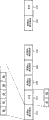
In the first embodiment of the present invention, encoder is arranged to and transmits the image head that repeats after the frame in each frame.So, provide the data that data storage 114 is repeated with temporary transient storage.Among first embodiment, for frame in each frame, image head 80 and first repeatedly is transferred to the receiving terminal decoder as segment data 82.Therefore, the data of form shown in the encoder output map 5.
As shown in Figure 5, the signal behind the coding starts from the data of first image 510 in the vision signal.This frame is intraframe coding.Comprise in the data 82 of image head 80, the first picture section and first image head 84 and the data 86 of each picture section subsequently in the data.Then, the image head 80 of first image 510 repeats into data 512 with first as segment data 82, and the image head of this repetition has and resembles identical time reference TR the primitive frame.After the data of this repetition is the data of inter-frame encoding frame 520,522,524 subsequently.In the next frame of coding during frame, after the data 510 of this frame be that frame 510 ' repeats in the frame 512 ', it comprises the image head 80 and the first picture segment data 82.
This configuration is for 28.8kbps code check and QCIF image, and frame will be introduced the expense of about 227 bytes in each frame.
So the receiving terminal decoder will receive dual header information.In this scheme, the job placement of decoder is selected (RPS) pattern as the explanation in the appendix N in H.263 with reference to reference picture wherein.According to appendix N H.263, if a decoder receives the two or more image heads with identical time reference (TR), then decoder is left out of account to second and subsequently image head (and their related data).Therefore, if the receiving terminal decoder can correctly be controlled the decoding (and reading the TR of this head) for the image head that occurs first thereupon, then this decoder will be ignored the image head of repetition.Therefore, can work ordinatedly with the decoder of routine according to the encoder of first embodiment of the invention, but this configuration can not obtain advantage of the present invention.Yet it provides compatibility.
Among the first above-mentioned embodiment, the data of repetition relate to the first picture segment data in a frame interior local part, particularly image head and image.So, by detecting the data of an incomplete frame that has received, can detect the existence of repeating data according to decoder of the present invention, and use the decoding that the data of being stored are finished this frame.
Among one second embodiment according to the present invention's encoder, add for bitstream encoded and to go up redundant frame of video.A kind of like this frame of video of redundancy should not be used for the video sequence of transmission is carried any additional information.The head that the application redundant frame substitutes in the previous image repeats.By means of according to encoder of the present invention, redundant frame can be added on the video bit stream.Can notify lucidly with the existing of redundant frame to decoder, perhaps, decoder can be used the existence that characteristic implicit in the redundant frame detects a kind of like this redundant frame.
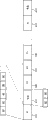
Fig. 6 shows bright according to the frame structure of second embodiment of the invention by the signal of an encoder output.The configuration of encoder can produce and transmit a redundant frame 612 after the frame 610 in each frame.According to H.263, unless select the reference picture among the appendix N to select (RPS) pattern, compressed image in succession can not be represented the same image that does not compress.The second embodiment of the present invention does not also rely on selecteed RPS.Under this occasion, the image head just is stored in the data storage 114.Under the control of controller 105, image head 80 originally changes in this wise, and promptly new image head 80 ' is identical with the interior frame 610 of frame, but the image encoding type in the PTYPE field is changed into P from I, and the TR field increment 1 again.Controller 105 is provided with a field 88 again, and it has indicated full frame and has not changed on data content.In H.263, include macro block indication (COD) identifier of a coding in this field, it puts 1 for the macro block of interframe encode.When it puts 1, show that this macro block do not send out further information (yet being the information no change).Inter-frame 620,622,624 subsequently resembles the inter-frame 520,522,524 shown in Fig. 5 coding in an identical manner, transmits the arrival of frame 610 ' in next frame.
According to an alternative embodiment of the invention, redundant frame in being included in frame after the frame, be also included within after the inter-frame.
Include the image head 80 ' of about 50 bits, the COD of 99 bits (99 each 1 bits of macro block in a QCIF image) and some filling bits (so that reaching the overall bit number of a whole frame) in the repeating data 612 of redundant frame.Stack up, such redundant frame typically is made up of 19 bytes, thereby for H.263 code check and the QCIF image of 28.8kbps, data flow has increased by about 8% expense.This amount of overhead just is applicable to when frame in each frame and each inter-frame are associated with a redundant frame.Obviously, the redundant frame of after frame in each frame, encoding, then expense can reduce.
As the explanation of being done with reference to figure 5 and Fig. 6, the image head that repeats in frame is provided at the back of original data in this frame of an image, again in the front of next frame data.
The 3rd embodiment of encoder is described now.Present embodiment is based on increasing newly " supplemental enhancement information " field (appendix L) in H.263.This increase can repeat some the image layer field in the previous image in the supplemental enhancement information in current images.(the image layer field does not repeat in same image, because they have the danger that is used as image layer data itself and is disturbed at one time).
According to H.263, the supplemental enhancement information that comprises in the image head is indicated by an identifier PEI.If PEI puts 1, it indicates in 8 bit field PSUPP back side information.Another PEI will indicate, and there is further side information another PSUPP back, and the like.
For the decoder of the extended capability of not supporting to illustrate among the appendix L, when PEI put 1, decoder design became to give up PSUPP.Like this, the extended capability in can backwards-compatible appendix L is not even support the decoder of this class ability need not do to change to utilize the bit stream that is using extended capability therein yet.
The form of the supplemental enhancement information that transmits in the PSUPP field of the image layer of this suggestion has been described among the appendix L H.263.The existence of this supplemental enhancement information indicates in PEI, and inserts an additional PEI bit between the PSUPP of per 8 bits data.
On the composition of PSUPP data, be the supplemental characteristic size standard DSIZE that after the function type indication FTYPE of 4 bits, follows 4 bits, follow the functional parameter data of some DSIZE bytes again, follow another function type indication again alternatively, and the like.When one the decoder of support function type indication did not receive a function type indication, it gave up the functional parameter data that are used for this function, and then, the function type subsequently of checking it to support is indicated.FTYPE numerical value has been made definition, they be shown in H.263 table L.1 in.This embodiment requirement of the present invention is done some change to appendix L H.263.These changes are:
1. defined a new function type indication at H.263 table in L.1
(FTYPE), for example be that bar item 13-image layer data repeat; And
2. comprise a explanation among the appendix L about the effect of this FTYPE code,
For example:
The coded representation that should application image layer data repeat function comes some field in the image layer data of repetition previous image.The field that repeats should be by the appearance that begins from time reference (TR) field of the syntactic order of person's character.In other words, if from the image layer data that repeat, remove the PEI bit, then bit stream repeat will be identical like that definitely with original bit stream on the relevant position.The DSIZE field has indicated the number of repetition byte among the SEI.Reservation DSIZE equals 0 state for using in the future.Then, after the eight bit byte of FTYPE/DSIZE, follow the image header information.
When recovering an image head of being disturbed, owing to before receiving next image starting end this recovery can not take place, so the embodiment of face before the ratio, this suggesting method can be introduced significant time-delay.Yet, because the work of decoder is usually faster than real-time video-transfer of data of moving on low frame rate at least, so decoder can have the idle time to wait the arrival of next frame image mostly.
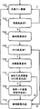
In the flow chart shown in realization may mode be given on Fig. 7 according to the encoder of the 3rd embodiment a kind of.For this embodiment, the image head is meant the image layer data of bitstream syntax meta before supplemental enhancement information.
Unpressed signal inputs to (700) on the encoder with certain frame frequency.Decision making by a Bit-Rate Control Algorithm algorithm, whether a concrete frame is encoded or jumped over (702).If a frame will be encoded, coded image head (704) at first then.The image head is stored into (708) in the data storage 114 again.In office going up in a flash only need be not more than three image head, also is the head of present image and the head of previous two coded images.Encoder is according to the image head of present image and previous image, and whether the GFID that determines in (706) this image will change (comparing with previous image).If the GFID of previous image also is different from the GFID (710) of its previous image, the image head that then needs to repeat previous image strengthens information as a supplement.Otherwise receiver or use the GFID of present image or use the GFID of the previous image of elder generation of previous image can recover the image head (712) of previous image.At last, the encode remainder (714) of this image.Then, from starting end coding circulation continue (700).
The image head that repeats can not need PSC in repetition.Another kind of situation can be handled head by the error correction sign indicating number of a systematic code.Systematic code error correction sign indicating number is such, and wherein, a preceding k symbol is a real messages, and remaining symbol is used for error correction.Under this concrete occasion, a preceding k bit is the image head, and remaining bit transmits as the supplemental enhancement information in the next frame.Therefore, the selection of error correction sign indicating number has influence on can detect and correct for what anti-phase error code bits, what needs replenish bit again this error code correction is provided.
Among the embodiment of encoder 100 described above, it repeats the transmitted image head for encoder 100 pre-programmed.Yet encoder 100 can be arranged to an order that comes in response to decoder and the repetition or the refreshed image data of adding.
Additionally or under the another kind of situation, encoder can be arranged to when each GFID parameter change state, repeats to transmit an image head.
Consider that terminal 1 receives the coding video frequency data of self terminal 2, referring now to the work of its decoding function explanation according to the present invention's video coder-decoder 10.Terminal 1 receives a multi-media signal from sending side terminal 2.50 pairs of multi-media signals of demodulation multiplexer carry out demultiplexing, make each signal behind the demultiplexing go to relevant portion in the receiver, for example, video data is gone to Video Codec 10, voice data is gone to audio codec 20, and H.245 control data is gone to H.245 controller 40.Decoder 200 in the Video Codec 10 is by inverse quantization, anti-DCJ conversion and to the motion compensation of data, with the video data decoding of coding.Then, the video data that decodes exports on the display 70 in the receiving side terminal 1, for reproduction.
As shown in Figure 4, include variable length decoding device 218, inverse DCT 220, anti-DCJ converter 221, motion compensator 222, video memory 223, controller 224, temporary transient image data memory 288 and switch 230 and 232 in the decoder section 200 of Video Codec 10.Controller 224 receives by the demodulation multiplexer 50 Video Codec control signal that demultiplexing goes out from the media stream of coding.In fact, the controller 224 in controller in the encoder 105 and the decoder can be same processor.
224 pairs of integralities that receive data of controller in the decoder are tested.A probable bit error in the image head means that this image can not decode out, has lost fully, and perhaps image head itself is disturbed that in fact it has lost.
First embodiment of decoder is described now.Under the operate as normal, by the data of decoder 200 received codes.The data that variable length decoding device (VLD) 218 decodings receive attempt to recover its form, the original frame structure shown in Fig. 3.That is to say, make coded data go compression, by the image initial code (PSC) in the controller 224 detection received data by VLD 218.Then, information Control inverse DCT 220 and the switch 230 in the controller 224 application image heads.When PTYPE information indicates is in the frame during frame, and switch 230 disconnects, and the output of anti-DCT device 221 just inputs to video memory 223.When PTYPE information indicates when being an inter-frame, switch 230 closures, the content in the video memory 223 will join in the output (predicated error that decodes) of anti-DCT device 221 by adder 234.
If decoder can not decode first image head, but other picture section in can detected image (for example, the GBSC of the second picture section 84), then decoder is gone into temporary transient image data memory 228 with this storage.When decoder received, decodes and identify the header data (and first picture segment data 82) of repetition, decoder was just used all the other information that data in the temporary transient image data memory 228 are recovered image.
Therefore, if controller 224 begins to detect less than a PSC (or determine this image head be interfered) a frame, but (for example detect a picture section head, by means of detecting a GOB initial code GBSC), then controller 224 changes the state of switch 232, and the data output commentaries on classics from VLD 218 is inputed on the temporary transient image data memory 228.Because can not being synchronized with image, this VLD begins the place, so these data will be from the GBSC sign indicating number that detects.
With reference to figure 5, suppose that decoder has detected GBSC in the head 84 for the second picture section of frame 510.So, will include content in the data of storage in the temporary transient image data memory 228, just the data of the head of the data of the head of the second picture section, the second picture section, the 3rd picture section, the 3rd picture section etc. in the frame 510 from head 84.
If the image head of losing/being disturbed belongs to frame in the frame, then the next data that received by decoder will be the image head and the first picture segment datas 512 of repetition.Decoder receives data 512, the first picture segment data 82 that it is associated with the image head 80 of repetition and repeats.Controller 224 detects the PSC in the repeating datas 512, reads the PTYPE field in the head, instructs inverse DCT 220 to be applied to inverse quantization then, and cut-off switch 230, with in response to this PTYPE field in the head that is indicated as being frame in the frame.Remaining duplicate message (just, the first picture segment data of repetition) is decoded by inverse DCT 220 and idct transform device 221, and the first picture section that decodes, repeat outputs to video memory 223 from IDCT 222.
Decoder can identify, these data are not the data of a complete image, for example be that the first image head 80 as section, back are with view data 82, and the back is with the then image head of a frame is arranged, decoder just decodes repeating data 512, detect then then, another frame also is the initial code of frame 520.This detection to decoder plays response, and controller 224 changes the state of switch 232, and the data of the frame 510 of temporary transient image data memory 228 stored are exported on inverse DCT 220 and the idct transform device 221.Then, the data of decoding export video memory 223 to, with the content of remaining decoded data update image memory 223 in the present image.
As described above, among first embodiment according to the present invention's decoder, decoder detects the reception of the image head that repeats by the appearance situation of detected image head, because after this image head be not the data of following a complete image (for example, image heel be the data of one of image picture section rather than more picture sections).Also can use the repetition that other method detects head.
As the explanation of front, if decoder decoded frame 510 correctly, then when signal formatd as illustrated in fig. 5, decoder can be given up the head 512 of repetition simply.
Fig. 8 illustrates a flow chart, has shown the method according to a decoder of first embodiment of the invention operation.At first, whether next sign indicating number is image initial code (PSC) in the data that decoder 200 is come by inspection, and the signal (400) of the reception that begins to decode.Be interfered (402) if the image head seems, then controller is gone into (404) in the temporary transient image data memory 228 with the associated image data storage of all the other each picture sections in the image.
Can variety of methods determine whether image is interfered.The method of some example is: whether decoder can not detect PSC; Whether a kind of bit error detection method (such as the CRC check in H.263 and) indicate and have error code; Perhaps in the image head, whether found unusual parameter (for example, when the type of coding of image head is a frame in the frame, and when in a picture section head, being set at the inter-frame identifier).
Common code error hiding technology can be used for hiding the error code in the image that causes because of transmission error or decode error at that time.Usually, if think the decoding frame in error code too many, decoder also can transmit a update request to encoder.
Common decoder will be reached a conclusion after the data that receive an incomplete frame, and the data of disappearance are lost in transmission.So decoder can send two field picture request in the frame in a known manner.Therefore, can not work with meeting decoder cooperation of the present invention according to encoder of the present invention.
Now, second embodiment according to the present invention's decoder is described.Reference is the signal of form as shown in Figure 6, if decoder can not decode head original in the frame 610, then decoder is stored into remaining view data (84,86) in this frame in the temporary transient image data memory 228.The first picture section of frame is not stored, because it can not decoded device identification.When receiving redundant frame 612, decoder will be read its data inter-frame codings as not changing.Usually do not provide this information (it seems that it be 100% redundancy) according to the encoder of prior art.Be indicated as being this situation appearance of unconverted field if detect inter-frame image head heel with one, just detect the image head that receives a repetition according to decoder of the present invention.After receiving this kind data, this inter-frame image head of decoder application is come structure group decoder, and the information of decoding then and coming from former frame is stored in the memory 228.
In the present embodiment, the data of image first picture section do not repeat, so can think and lost.Therefore, receive the header data of repetition after, decoder makes switch 232 change states, thus the second picture section plays the content of refreshed image data.Another kind of situation, decoder might estimate that first a picture section view data should begin wherefrom in the data of being disturbed, and decode data from this aspect.For example, supposing in the image head of original image has the error code of a bit inversion, so can not decode this image head.But, PSC is still correct, so can detect the beginning of frame reliably.So, entire image 610 is stored in the temporary transient image data memory 228, when receiving the head of repetition, expecting that the image head finishes and expecting that the initial place of the first picture segment data, decoder 200 begin the data of decoding and being stored then.
So, the data of decoder inspection arrival.If the image head is lost or disturbed, just the remainder data in the frame is stored into temporary transient image data memory 228.Then, subsequently data of decoding, and if this data when being associated with inter-frame and indicating in the image no change, just the decoded picture head is used the data of coming in the information decoding image data memory 228 in the image head of redundant frame simultaneously.
When signal format as shown in Figure 6 the time, if the operation of the decoder image head of decoded frame 610 correctly, then decoder will continue, the head 612 that decoding repeats.As with reference to bright as shown in the figure 6, include image head 82 (TR that comprises an increment) and one in the information 612 of repetition and indicate the field 88 that with respect to previous coded frame, does not have data variation.Since there is not storage in temporary image data memory 228, so decoder will be given up the data 612 of this redundant frame, and decoding frame 620 subsequently.
After the encoded signals of the 3rd embodiment that receives according to the present invention, according to the data that a decoder application of the present invention is followed after the FTYPE/DSIZE eight bit byte in the supplemental enhancement information (SEI) in the frame of following, the data of image data memory 228 stored of decoding temporary transient.
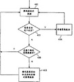
The 3rd embodiment of decoders is described with reference to figure 9 now.Present embodiment has utilized the front with reference to encoder and the illustrated SEI method of Fig. 7.
The work of decoder is as described below.At first (900), decoder receive the image head in the next images.If this image head does not have error code (901), decoder this image head (902) of can decoding without a doubt then.Then, the remainder data (904) that it can decoded picture.If detect some error code (901) in the image head, then decoder is searched picture section (GOB or the picture bar) head (906) of first no error code in the image.With this bit stream position as first sync bit again.If identical (908) in the GFID of this head and the previous image, then decoder can recover the key component (910) in this image head, and begins to continue decoding (904) from this concrete picture section.If different (908) in GFID and the previous image, then decoder is searched next image initial code (912).Repeat (914) if include SEI image head in the image layer data of image, then decoder can recover the image head (916) of present image.Decoded positions in the bit stream must be set again and get back to first (918) on sync bit again.Repeat (914) if do not comprise SEI image head in the image layer data, then decoder is searched a next picture section initial code (916), and makes check (920), and whether the GFID in the head is identical with GFID in the decoded image.If two GFID are equal to, then decoder can recover image head (910), and from the first sync bit continuation decoding again.If two GFID are different, then decoder never recovers the head disturbed.Under this kind occasion (922), for example can ask frame update in the frame.
Temporary transient image data memory can be stored the coded data of multiframe.Because the most of frames in the low bit-rate applications are encoded in the inter-frame mode, so most of data of storing in the temporary transient image data memory have been represented prediction error data mostly, so data volume is compact.So temporary transient image data memory should be stored data fully, be used for frame and the data that inter-frame is required at least one frame.For the PCIF image of bit rate 28.8kbps, an inter-frame typically is encoded into about 250 bytes.
If any data of each frame of video also are stored in the temporary transient image data memory 228 subsequently, then these data are also decoded, export in the video memory 223, make the content alignment in the respective memory of the content of video memory 223 and transmitting device.
Claims (10)
1. the method for a video frequency source coding, this method comprises:
-generating the bit stream part of first source code represent first frame of video, the bit stream of this first source code partly comprises the view data of the corresponding source code of the image header data of this first frame of video and whole described first frame of video;
-use error correcting code to arrive the image header data of this first frame of video to generate error correction data;
-generate representative in coded sequence first frame of video back with the bit stream part of second source code of second frame of video, the bit stream of this second source code partly comprises the image header data of this second frame of video and the view data of whole described second frame of video; And
-in the supplemental enhancement information (SEI) of this second frame of video, this error correction data is set.
2. the method for video source decoding, this method comprises:
-receiving bit stream at least a portion partly of first source code represent first frame of video, the bit stream of this first source code partly comprises the view data of the corresponding source code of the image header data of this first frame of video and whole described first frame of video;
-receive representative in coded sequence this first frame of video back with the bit stream part of second source code of second frame of video; And
-from the supplemental enhancement information (SEI) of this second frame of video, obtain the error correction data of the image header data of this first frame of video, be used for when the image header data of determining this first frame of video has been destroyed, the image header data of this first frame of video being carried out error correction.
3. equipment that is used for video frequency source coding, wherein this equipment is arranged to:
-generating the bit stream part of first source code represent first frame of video, the bit stream of this first source code partly comprises the view data of the corresponding source code of the image header data of this first frame of video and whole described first frame of video;
-use error correcting code to arrive the image header data of this first frame of video to generate error correction data;
-generate representative in coded sequence first frame of video back with the bit stream part of second source code of second frame of video, the bit stream of this second source code partly comprises the image header data of this second frame of video and the view data of whole described second frame of video; And
-in the supplemental enhancement information (SEI) of this second frame of video, this error correction data is set.
4. encoder, wherein this encoder is arranged to:
-generating the bit stream part of first source code represent first frame of video, the bit stream of this first source code partly comprises the view data of the corresponding source code of the image header data of this first frame of video and whole described first frame of video;
-use error correcting code to arrive the image header data of this first frame of video to generate error correction data;
-generate representative in coded sequence first frame of video back with the bit stream part of second source code of second frame of video, the bit stream of this second source code partly comprises the image header data of this second frame of video and the view data of whole described second frame of video; And
-in the supplemental enhancement information (SEI) of this second frame of video, this error correction data is set.
5. encoder comprises:
-being used to generate the device of the bit stream part of first source code of representing first frame of video, the bit stream of this first source code partly comprises the view data of the corresponding source code of the image header data of this first frame of video and whole described first frame of video;
-be used to use error correcting code to arrive the image header data of this first frame of video to generate the device of error correction data;
-be used for generating representative coded sequence first frame of video back with the device of bit stream part of second source code of second frame of video, the bit stream of this second source code partly comprises the image header data of this second frame of video and the view data of whole described second frame of video; And
-be used for being provided with the device of this error correction data in the supplemental enhancement information (SEI) of this second frame of video.
6. an encoder comprises controller, and this controller is arranged to:
-generating the bit stream part of first source code represent first frame of video, the bit stream of this first source code partly comprises the view data of the corresponding source code of the image header data of this first frame of video and whole described first frame of video;
-use error correcting code to arrive the image header data of this first frame of video to generate error correction data;
-generate representative in coded sequence first frame of video back with the bit stream part of second source code of second frame of video, the bit stream of this second source code partly comprises the image header data of this second frame of video and the view data of whole described second frame of video; And
-in the supplemental enhancement information (SEI) of this second frame of video, this error correction data is set.
7. one kind is used for the equipment that video source is decoded, and wherein this equipment is arranged to:
-receiving bit stream at least a portion partly of first source code represent first frame of video, the bit stream of this first source code partly comprises the view data of the corresponding source code of the image header data of this first frame of video and whole described first frame of video;
-receive representative in coded sequence this first frame of video back with the bit stream part of second source code of second frame of video; And
-from the supplemental enhancement information (SEI) of this second frame of video, obtain the error correction data of the image header data of this first frame of video, be used for when the image header data of determining this first frame of video has been destroyed, the image header data of this first frame of video being carried out error correction.
8. video source decoder, wherein this video source decoder is arranged to:
-receiving bit stream at least a portion partly of first source code represent first frame of video, the bit stream of this first source code partly comprises the view data of the corresponding source code of the image header data of this first frame of video and whole described first frame of video;
-receive representative in coded sequence this first frame of video back with the bit stream part of second source code of second frame of video; And
-from the supplemental enhancement information (SEI) of this second frame of video, obtain the error correction data of the image header data of this first frame of video, be used for when the image header data of determining this first frame of video has been destroyed, the image header data of this first frame of video being carried out error correction.
9. video source decoder, this video source decoder comprises:
-being used to receive the device of at least a portion of the bit stream part of first source code of representing first frame of video, the bit stream of this first source code partly comprises the view data of the corresponding source code of the image header data of this first frame of video and whole described first frame of video;
-be used for receiving representative this first frame of video of coded sequence back with the device of bit stream part of second source code of second frame of video; And
-be used for being used for the device that when the image header data of determining this first frame of video has been destroyed, the image header data of this first frame of video carried out error correction from the error correction data that the supplemental enhancement information (SEI) of this second frame of video is obtained the image header data of this first frame of video.
10. a video source decoder comprises controller, and this controller is arranged to:
-receiving bit stream at least a portion partly of first source code represent first frame of video, the bit stream of this first source code partly comprises the view data of the corresponding source code of the image header data of this first frame of video and whole described first frame of video;
-receive representative in coded sequence this first frame of video back with the bit stream part of second source code of second frame of video; And
-from the supplemental enhancement information (SEI) of this second frame of video, obtain the error correction data of the image header data of this first frame of video, be used for when the image header data of determining this first frame of video has been destroyed, the image header data of this first frame of video being carried out error correction.
Applications Claiming Priority (2)
| Application Number | Priority Date | Filing Date | Title |
|---|---|---|---|
| GB9916909A GB2352350B (en) | 1999-07-19 | 1999-07-19 | Video coding |
| GB9916909.6 | 1999-07-19 |
Related Parent Applications (1)
| Application Number | Title | Priority Date | Filing Date |
|---|---|---|---|
| CN00810573A Division CN1361991A (en) | 1999-07-19 | 2000-07-14 | Video coding |
Publications (1)
| Publication Number | Publication Date |
|---|---|
| CN101790099A true CN101790099A (en) | 2010-07-28 |
Family
ID=10857513
Family Applications (3)
| Application Number | Title | Priority Date | Filing Date |
|---|---|---|---|
| CN201010147737A Pending CN101790099A (en) | 1999-07-19 | 2000-07-14 | Video coding |
| CN2007101851538A Expired - Lifetime CN101175213B (en) | 1999-07-19 | 2000-07-14 | Video source coding method and device, method and device for decoding video source |
| CN00810573A Pending CN1361991A (en) | 1999-07-19 | 2000-07-14 | Video coding |
Family Applications After (2)
| Application Number | Title | Priority Date | Filing Date |
|---|---|---|---|
| CN2007101851538A Expired - Lifetime CN101175213B (en) | 1999-07-19 | 2000-07-14 | Video source coding method and device, method and device for decoding video source |
| CN00810573A Pending CN1361991A (en) | 1999-07-19 | 2000-07-14 | Video coding |
Country Status (14)
| Country | Link |
|---|---|
| US (3) | US7006576B1 (en) |
| EP (2) | EP1542475B1 (en) |
| JP (1) | JP4969003B2 (en) |
| KR (1) | KR100495820B1 (en) |
| CN (3) | CN101790099A (en) |
| AT (2) | ATE296015T1 (en) |
| AU (1) | AU774040B2 (en) |
| BR (1) | BRPI0011748B1 (en) |
| CA (1) | CA2377865C (en) |
| DE (1) | DE60020243T2 (en) |
| ES (1) | ES2240128T3 (en) |
| GB (1) | GB2352350B (en) |
| HK (1) | HK1114494A1 (en) |
| WO (1) | WO2001006795A1 (en) |
Families Citing this family (56)
| Publication number | Priority date | Publication date | Assignee | Title |
|---|---|---|---|---|
| GB2352350B (en) | 1999-07-19 | 2003-11-05 | Nokia Mobile Phones Ltd | Video coding |
| JP4224662B2 (en) * | 2000-08-09 | 2009-02-18 | ソニー株式会社 | Image encoding apparatus and method, image decoding apparatus and method, and image processing apparatus |
| TW533738B (en) * | 2000-10-31 | 2003-05-21 | Matsushita Electric Ind Co Ltd | Received information record/regenerate method and received information record/regenerate device |
| US20040022202A1 (en) * | 2002-08-05 | 2004-02-05 | Chih-Lung Yang | Method and apparatus for continuously receiving images from a plurality of video channels and for alternately continuously transmitting to each of a plurality of participants in a video conference individual images containing information concerning each of said video channels |
| JP2003208343A (en) * | 2002-01-10 | 2003-07-25 | Ricoh Co Ltd | File creation/browsing method, file creating method, file browsing method, file structure and program |
| AU2003226081A1 (en) * | 2002-03-25 | 2003-10-13 | The Trustees Of Columbia University In The City Of New York | Method and system for enhancing data quality |
| KR100557047B1 (en) * | 2002-10-21 | 2006-03-03 | 엘지전자 주식회사 | Method for moving picture decoding |
| KR20040046540A (en) * | 2002-11-27 | 2004-06-05 | 엘지전자 주식회사 | Method for moving picture decoding |
| KR20040046895A (en) * | 2002-11-28 | 2004-06-05 | 엘지전자 주식회사 | Data Unit Process Based On H.223 CRC Error Check In Video Telephony System |
| US7474792B2 (en) * | 2002-12-02 | 2009-01-06 | Ricoh Company, Ltd. | Image processing apparatus for using distortion amount information |
| JP4002878B2 (en) * | 2003-01-17 | 2007-11-07 | 松下電器産業株式会社 | Image coding method |
| FR2852180B1 (en) * | 2003-03-07 | 2005-08-26 | Thales Sa | METHOD AND SYSTEM FOR DATA PROTECTION WITH HEADER IN A TRANSMISSION SYSTEM |
| JP2004336727A (en) | 2003-04-17 | 2004-11-25 | Sharp Corp | Wireless control system, control device, controlled device, device control method, control program, and computer-readable recording medium recording the same |
| US20040218669A1 (en) * | 2003-04-30 | 2004-11-04 | Nokia Corporation | Picture coding method |
| KR100586101B1 (en) * | 2003-05-12 | 2006-06-07 | 엘지전자 주식회사 | Moving picture coding method |
| KR101103867B1 (en) * | 2003-09-07 | 2012-01-12 | 마이크로소프트 코포레이션 | Slice layer in video codec |
| US7447382B2 (en) * | 2004-06-30 | 2008-11-04 | Intel Corporation | Computing a higher resolution image from multiple lower resolution images using model-based, robust Bayesian estimation |
| US7809155B2 (en) | 2004-06-30 | 2010-10-05 | Intel Corporation | Computing a higher resolution image from multiple lower resolution images using model-base, robust Bayesian estimation |
| US20060104350A1 (en) * | 2004-11-12 | 2006-05-18 | Sam Liu | Multimedia encoder |
| US8780957B2 (en) | 2005-01-14 | 2014-07-15 | Qualcomm Incorporated | Optimal weights for MMSE space-time equalizer of multicode CDMA system |
| KR100763178B1 (en) * | 2005-03-04 | 2007-10-04 | 삼성전자주식회사 | Method for color space scalable video coding and decoding, and apparatus for the same |
| US9197912B2 (en) * | 2005-03-10 | 2015-11-24 | Qualcomm Incorporated | Content classification for multimedia processing |
| JP4618676B2 (en) * | 2005-04-28 | 2011-01-26 | 株式会社リコー | Structured document code transfer method, image processing system, server device, program, and information recording medium |
| TW200714077A (en) * | 2005-09-20 | 2007-04-01 | Ali Corp | Image processing method and a 2-D discrete cosine transformation device thereof |
| US8879635B2 (en) | 2005-09-27 | 2014-11-04 | Qualcomm Incorporated | Methods and device for data alignment with time domain boundary |
| US8948260B2 (en) | 2005-10-17 | 2015-02-03 | Qualcomm Incorporated | Adaptive GOP structure in video streaming |
| US20070206117A1 (en) * | 2005-10-17 | 2007-09-06 | Qualcomm Incorporated | Motion and apparatus for spatio-temporal deinterlacing aided by motion compensation for field-based video |
| US8654848B2 (en) * | 2005-10-17 | 2014-02-18 | Qualcomm Incorporated | Method and apparatus for shot detection in video streaming |
| US20070171280A1 (en) * | 2005-10-24 | 2007-07-26 | Qualcomm Incorporated | Inverse telecine algorithm based on state machine |
| US7684626B1 (en) * | 2005-12-01 | 2010-03-23 | Maxim Integrated Products | Method and apparatus for image decoder post-processing using image pre-processing and image encoding information |
| KR100799998B1 (en) * | 2006-02-14 | 2008-01-31 | 엘지전자 주식회사 | Digital broadcasting receiver and method for processing data error in the same |
| US20070189383A1 (en) * | 2006-02-15 | 2007-08-16 | Samsung Electronics Co., Ltd. | Method and system for appending redundancy to uncompressed video for transmission over wireless communication channels |
| US9131164B2 (en) * | 2006-04-04 | 2015-09-08 | Qualcomm Incorporated | Preprocessor method and apparatus |
| US9872045B2 (en) * | 2006-10-16 | 2018-01-16 | Conversant Wireless Licensing S.A R.L. | Method, electronic device, system, computer program product and circuit assembly for reducing error in video coding |
| TWI435612B (en) * | 2007-02-23 | 2014-04-21 | Nokia Corp | Backward-compatible characterization of aggregated media data units |
| EP2127398A2 (en) * | 2007-03-29 | 2009-12-02 | Nxp B.V. | Speed up video recovery of videotelephony after an interruption |
| BRPI0809210A2 (en) * | 2007-04-04 | 2014-09-02 | Thomson Licensing | REFERENCE IMAGE LIST MANAGEMENT |
| US8462855B2 (en) * | 2007-09-26 | 2013-06-11 | Intel Corporation | Method and apparatus for stream parsing and picture location |
| US8332736B2 (en) * | 2007-11-29 | 2012-12-11 | Texas Instruments Incorporated | Decoder with resiliency to handle errors in a received data stream |
| JP5147546B2 (en) * | 2008-05-30 | 2013-02-20 | キヤノン株式会社 | Video encoding device and video decoding device |
| US20100158130A1 (en) * | 2008-12-22 | 2010-06-24 | Mediatek Inc. | Video decoding method |
| US8942543B1 (en) | 2010-10-06 | 2015-01-27 | Verint Video Solutions Inc. | Systems, methods, and software for improved video data recovery effectiveness |
| JP5496047B2 (en) * | 2010-10-07 | 2014-05-21 | パナソニック株式会社 | Image reproduction method, image reproduction apparatus, image reproduction program, imaging system, and reproduction system |
| CA2856909C (en) * | 2011-12-04 | 2016-12-06 | Lg Electronics Inc. | Digital broadcasting reception method and apparatus capable of displaying stereoscopic images |
| CA2898147C (en) * | 2012-01-30 | 2017-11-07 | Samsung Electronics Co., Ltd. | Method and apparatus for video encoding for each spatial sub-area, and method and apparatus for video decoding for each spatial sub-area |
| US20140119445A1 (en) * | 2012-10-26 | 2014-05-01 | Lsi Corporation | Method of concealing picture header errors in digital video decoding |
| KR101979634B1 (en) | 2012-12-13 | 2019-05-20 | 삼성전자주식회사 | Image processing apparatus for image enhancement and method thereof |
| US20140269896A1 (en) * | 2013-03-13 | 2014-09-18 | Futurewei Technologies, Inc. | Multi-Frame Compression |
| US9407923B2 (en) * | 2013-05-20 | 2016-08-02 | Gamefly Israel Ltd. | Overconing lost IP packets in streaming video in IP networks |
| US9807408B2 (en) | 2014-08-27 | 2017-10-31 | Clearone Communications Hong Kong Ltd. | Control mechanism for video output |
| US9973795B2 (en) * | 2014-08-27 | 2018-05-15 | ClearOne Inc. | Method for video synchronization in video distribution systems |
| EP3276964A4 (en) * | 2015-03-27 | 2018-01-31 | Panasonic Intellectual Property Management Co., Ltd. | Video decoding device |
| US10291936B2 (en) | 2017-08-15 | 2019-05-14 | Electronic Arts Inc. | Overcoming lost or corrupted slices in video streaming |
| MX2022003559A (en) * | 2019-09-24 | 2022-06-14 | Huawei Tech Co Ltd | Signaling of picture header in video coding. |
| KR20220073834A (en) * | 2019-11-05 | 2022-06-03 | 엘지전자 주식회사 | High-level syntax signaling method and apparatus for video/video coding |
| WO2023242587A1 (en) * | 2022-06-16 | 2023-12-21 | Mbda Uk Limited | Method for image encoding |
Family Cites Families (27)
| Publication number | Priority date | Publication date | Assignee | Title |
|---|---|---|---|---|
| US4972261A (en) * | 1987-08-28 | 1990-11-20 | The General Electric Company, P.L.C. | Motion compensation image signal encoding system |
| EP0441168B1 (en) | 1990-02-06 | 1996-10-16 | ALCATEL ITALIA Società per Azioni | System, packet structuring and device for processing output information from a signal encoder |
| JPH0490648A (en) * | 1990-08-06 | 1992-03-24 | Fujitsu Ltd | Coded transmission system |
| JPH0498987A (en) * | 1990-08-16 | 1992-03-31 | Matsushita Electric Ind Co Ltd | Error correction method |
| US5168356A (en) * | 1991-02-27 | 1992-12-01 | General Electric Company | Apparatus for segmenting encoded video signal for transmission |
| US5289276A (en) | 1992-06-19 | 1994-02-22 | General Electric Company | Method and apparatus for conveying compressed video data over a noisy communication channel |
| US5497404A (en) * | 1992-07-14 | 1996-03-05 | General Instrument Corporation | Transmission error recovery for digital communication systems using variable length data packets where data is stored in header locations of memory |
| JPH06237451A (en) * | 1993-02-10 | 1994-08-23 | Hitachi Ltd | Moving picture communication system and terminal equipment |
| JP3428697B2 (en) * | 1993-09-07 | 2003-07-22 | キヤノン株式会社 | Image decoding method |
| US5376969A (en) | 1993-11-15 | 1994-12-27 | Rca Thomson Licensing Corporation | Method and apparatus for conveying compressed video data over a noisy communication channel |
| JP2671821B2 (en) | 1994-09-28 | 1997-11-05 | 日本電気株式会社 | Data transmission equipment |
| US5550847A (en) * | 1994-10-11 | 1996-08-27 | Motorola, Inc. | Device and method of signal loss recovery for realtime and/or interactive communications |
| DE19524808A1 (en) | 1995-07-07 | 1997-01-09 | Thomson Brandt Gmbh | Process, encoder and decoder for resynchronization to a faulty data stream |
| US5754605A (en) * | 1995-09-29 | 1998-05-19 | Motorola | Method and apparatus for synchronization of a communications unit |
| JPH09207995A (en) | 1996-02-01 | 1997-08-12 | Nas Toa Co Ltd | Fitting for draft beer barrel |
| JPH1174868A (en) * | 1996-09-02 | 1999-03-16 | Toshiba Corp | Information transmission method, coder/decoder in information transmission system adopting the method, coding multiplexer/decoding inverse multiplexer |
| US5875305A (en) | 1996-10-31 | 1999-02-23 | Sensormatic Electronics Corporation | Video information management system which provides intelligent responses to video data content features |
| US5912902A (en) * | 1997-03-14 | 1999-06-15 | Monroe; David A. | Data recovery scheme |
| JP3769347B2 (en) * | 1997-03-19 | 2006-04-26 | 株式会社 日立インダストリイズ | Gas turbine intake air cooling system |
| JP3580557B2 (en) | 1997-08-01 | 2004-10-27 | 株式会社エヌ・ティ・ティ・ドコモ | Data sequence generator, transmitter, information data decoder, receiver, transceiver, data sequence generation method, information data decoding method, and recording medium |
| US6631485B1 (en) * | 1998-01-16 | 2003-10-07 | Hewlett-Packard Development Company, L.C. | Methods and apparatus for data storage on magnetic media including error correction codes |
| US6243369B1 (en) * | 1998-05-06 | 2001-06-05 | Terayon Communication Systems, Inc. | Apparatus and method for synchronizing an SCDMA upstream or any other type upstream to an MCNS downstream or any other type downstream with a different clock rate than the upstream |
| US6301637B1 (en) * | 1998-06-08 | 2001-10-09 | Storage Technology Corporation | High performance data paths |
| US6826197B1 (en) * | 1999-04-01 | 2004-11-30 | Sedna Patent Services, Llc | Data packet structure for digital information distribution |
| JP3411234B2 (en) * | 1999-04-26 | 2003-05-26 | 沖電気工業株式会社 | Encoded information receiving and decoding device |
| GB2352350B (en) | 1999-07-19 | 2003-11-05 | Nokia Mobile Phones Ltd | Video coding |
| US6654389B1 (en) * | 1999-11-23 | 2003-11-25 | International Business Machines Corporation | System and method for searching patterns in real-time over a shared media |
-
1999
- 1999-07-19 GB GB9916909A patent/GB2352350B/en not_active Revoked
-
2000
- 2000-07-14 CN CN201010147737A patent/CN101790099A/en active Pending
- 2000-07-14 BR BRPI0011748A patent/BRPI0011748B1/en active IP Right Grant
- 2000-07-14 AT AT00949342T patent/ATE296015T1/en not_active IP Right Cessation
- 2000-07-14 DE DE60020243T patent/DE60020243T2/en not_active Expired - Lifetime
- 2000-07-14 WO PCT/EP2000/006732 patent/WO2001006795A1/en active IP Right Grant
- 2000-07-14 CN CN2007101851538A patent/CN101175213B/en not_active Expired - Lifetime
- 2000-07-14 KR KR10-2002-7000651A patent/KR100495820B1/en active IP Right Grant
- 2000-07-14 ES ES00949342T patent/ES2240128T3/en not_active Expired - Lifetime
- 2000-07-14 CN CN00810573A patent/CN1361991A/en active Pending
- 2000-07-14 AU AU62735/00A patent/AU774040B2/en not_active Expired
- 2000-07-14 AT AT05075667T patent/ATE533306T1/en active
- 2000-07-14 EP EP05075667A patent/EP1542475B1/en not_active Expired - Lifetime
- 2000-07-14 CA CA002377865A patent/CA2377865C/en not_active Expired - Lifetime
- 2000-07-14 JP JP2001510493A patent/JP4969003B2/en not_active Expired - Lifetime
- 2000-07-14 EP EP00949342A patent/EP1205076B1/en not_active Expired - Lifetime
- 2000-07-19 US US09/619,660 patent/US7006576B1/en not_active Expired - Lifetime
-
2005
- 2005-04-06 US US11/099,596 patent/US8654863B2/en not_active Expired - Fee Related
-
2007
- 2007-02-05 US US11/671,439 patent/US8401089B2/en active Active
-
2008
- 2008-09-10 HK HK08110054.4A patent/HK1114494A1/en not_active IP Right Cessation
Also Published As
| Publication number | Publication date |
|---|---|
| JP4969003B2 (en) | 2012-07-04 |
| CN101175213B (en) | 2011-02-09 |
| ATE296015T1 (en) | 2005-06-15 |
| BR0011748A (en) | 2002-03-05 |
| EP1542475A2 (en) | 2005-06-15 |
| GB9916909D0 (en) | 1999-09-22 |
| EP1542475A3 (en) | 2009-03-25 |
| CA2377865C (en) | 2009-11-10 |
| DE60020243T2 (en) | 2006-03-23 |
| KR100495820B1 (en) | 2005-06-16 |
| AU6273500A (en) | 2001-02-05 |
| CN1361991A (en) | 2002-07-31 |
| AU774040B2 (en) | 2004-06-17 |
| US8401089B2 (en) | 2013-03-19 |
| ATE533306T1 (en) | 2011-11-15 |
| JP2003504988A (en) | 2003-02-04 |
| US7006576B1 (en) | 2006-02-28 |
| EP1205076A1 (en) | 2002-05-15 |
| EP1205076B1 (en) | 2005-05-18 |
| US20050185719A1 (en) | 2005-08-25 |
| BRPI0011748B1 (en) | 2015-09-08 |
| ES2240128T3 (en) | 2005-10-16 |
| HK1114494A1 (en) | 2008-10-31 |
| EP1542475B1 (en) | 2011-11-09 |
| CA2377865A1 (en) | 2001-01-25 |
| GB2352350A (en) | 2001-01-24 |
| DE60020243D1 (en) | 2005-06-23 |
| US8654863B2 (en) | 2014-02-18 |
| US20070171986A1 (en) | 2007-07-26 |
| KR20020020937A (en) | 2002-03-16 |
| CN101175213A (en) | 2008-05-07 |
| WO2001006795A1 (en) | 2001-01-25 |
| GB2352350B (en) | 2003-11-05 |
Similar Documents
| Publication | Publication Date | Title |
|---|---|---|
| CN101175213B (en) | Video source coding method and device, method and device for decoding video source | |
| KR100931873B1 (en) | Video Signal Encoding/Decoding Method and Video Signal Encoder/Decoder | |
| CN100394802C (en) | Video signal encoding/decoding method and apparatus, and corresponding wireless communication device | |
| US7327791B1 (en) | Video decoding method performing selective error concealment and resynchronization | |
| CN101252696A (en) | Video coding | |
| US7124429B2 (en) | Video coding apparatus and video decoding apparatus | |
| JP3956081B2 (en) | Encoding method for digital video including gray shape information | |
| JP2000253398A (en) | Video packet generating system, video decoding system, media multiplexer, media demultiplexer and multimedia communication system | |
| CA2477554A1 (en) | Video processing | |
| KR100543607B1 (en) | Method for decoding of moving picture | |
| KR100557047B1 (en) | Method for moving picture decoding | |
| KR100557118B1 (en) | Moving picture decoder and method for moving picture decoding | |
| EP1349398A1 (en) | Video processing | |
| KR20040046539A (en) | Method for moving picture decoding | |
| KR20040046540A (en) | Method for moving picture decoding | |
| KR20050026110A (en) | Moving picture decoding and method for moving picture decoding |
Legal Events
| Date | Code | Title | Description |
|---|---|---|---|
| C06 | Publication | ||
| PB01 | Publication | ||
| C10 | Entry into substantive examination | ||
| SE01 | Entry into force of request for substantive examination | ||
| C12 | Rejection of a patent application after its publication | ||
| RJ01 | Rejection of invention patent application after publication |
Application publication date: 20100728 |