CN101789572A - Junction box for solar cell module - Google Patents
Junction box for solar cell module Download PDFInfo
- Publication number
- CN101789572A CN101789572A CN201010118329A CN201010118329A CN101789572A CN 101789572 A CN101789572 A CN 101789572A CN 201010118329 A CN201010118329 A CN 201010118329A CN 201010118329 A CN201010118329 A CN 201010118329A CN 101789572 A CN101789572 A CN 101789572A
- Authority
- CN
- China
- Prior art keywords
- diode
- box
- electric conductor
- terminal box
- heat
- Prior art date
- Legal status (The legal status is an assumption and is not a legal conclusion. Google has not performed a legal analysis and makes no representation as to the accuracy of the status listed.)
- Granted
Links
Images




Classifications
-
- Y—GENERAL TAGGING OF NEW TECHNOLOGICAL DEVELOPMENTS; GENERAL TAGGING OF CROSS-SECTIONAL TECHNOLOGIES SPANNING OVER SEVERAL SECTIONS OF THE IPC; TECHNICAL SUBJECTS COVERED BY FORMER USPC CROSS-REFERENCE ART COLLECTIONS [XRACs] AND DIGESTS
- Y02—TECHNOLOGIES OR APPLICATIONS FOR MITIGATION OR ADAPTATION AGAINST CLIMATE CHANGE
- Y02E—REDUCTION OF GREENHOUSE GAS [GHG] EMISSIONS, RELATED TO ENERGY GENERATION, TRANSMISSION OR DISTRIBUTION
- Y02E10/00—Energy generation through renewable energy sources
- Y02E10/50—Photovoltaic [PV] energy
Landscapes
- Photovoltaic Devices (AREA)
Abstract
一种太阳电池组件用接线盒,包括盒体、散热单元及设置在盒体中的至少两个互相没有直接电性连接的控制电路,控制电路包括二极管和至少一与二极管管脚相电连接的用于与汇流条连接的导电体,导电体与二极管为一体成型结构。本发明还公开了相应的二极管及散热器集成结构,以及相具有所述接线盒的太阳电池组件,通过本发明从根本上改变了二极管的尺寸和封装,把接线盒里的导电体和二极管的管脚集成于一体,并把绝缘导热介质集成于二极管的散热底部,散热效果非常好;另外本发明的接线盒密封性好,且便于系统安装,并节省系统成本。
A junction box for a solar cell module, comprising a box body, a heat dissipation unit, and at least two control circuits arranged in the box body that are not directly electrically connected to each other, the control circuit includes a diode and at least one electrical connection with the diode pin The conductor used to connect with the bus bar, the conductor and the diode are integrally formed. The invention also discloses the corresponding integrated structure of the diode and the heat sink, and the solar cell assembly with the junction box. The size and packaging of the diode are fundamentally changed by the invention, and the conductor in the junction box and the diode The pins are integrated, and the insulating and heat-conducting medium is integrated in the heat dissipation bottom of the diode, so that the heat dissipation effect is very good; in addition, the junction box of the present invention has good sealing performance, is convenient for system installation, and saves system cost.
Description
技术领域technical field
本发明涉及光伏领域,尤其涉及一种太阳电池组件用接线盒。The invention relates to the field of photovoltaics, in particular to a junction box for a solar battery module.
背景技术Background technique
近年来,在发展可替代能源方面,太阳电池技术获得巨大突破,应用也愈加广泛。太阳电池技术一般是通过太阳电池组件构成的光伏系统向外输出电能。目前的太阳电池组件一般由54至72片太阳电池串联而成,在太阳电池组件内部,为了保护太阳电池在发生热斑效应时不会被烧坏,通常是将太阳电池组件内部串联的太阳电池分成多个支路,每个支路并联一个旁路二极管来加以保护,比如是每一由18-24片太阳电池串联的支路并联一个旁路二极管,多个旁路二极管均设置在一个组件接线盒中,且安装在盒体内部的导电片或接线座上,接线盒具有引出电缆线,然后各接线盒利用电缆线和连接头相互连接从而实现太阳电池组件之间的连接。In recent years, in the development of alternative energy sources, solar cell technology has made great breakthroughs, and its applications have become more and more extensive. Solar cell technology generally outputs electric energy through a photovoltaic system composed of solar cell components. The current solar cell module is generally composed of 54 to 72 solar cells in series. Inside the solar cell module, in order to protect the solar cell from being burned out when the hot spot effect occurs, it is usually the solar cells connected in series inside the solar cell module Divided into multiple branches, each branch is connected in parallel with a bypass diode for protection, for example, each branch connected in parallel with 18-24 solar cells is connected in parallel with a bypass diode, and multiple bypass diodes are set in one component In the junction box, it is installed on the conductive sheet or the terminal seat inside the box body. The junction box has lead-out cables, and then the junction boxes are connected to each other by cables and connectors to realize the connection between solar cell modules.
这样的接线盒的缺陷是:由于组件均采用一个接线盒,所以组件之间相互连接时需要比较多的电缆线,而且由于接线盒的盒体与电缆的连接头是分离的,所以在系统安装时需要固定接线盒之间相连的电缆线以防止由于电缆线本身及连接头的重量导致的连接效果不稳定,如此会降低系统安装的效率;另外,旁路二极管是封闭在接线盒内,且由于接线盒内部与旁路二极管安装的导电片或接线座直接接触的都是导热性不良的介质,所以旁路二极管工作时产生的热量很难散出,这样会导致旁路二极管温度过高,会缩短旁路二极管的寿命、甚至使旁路二极管失效,进而使组件发生烧毁或质量下降。并且,接线盒的二极管与导电体通过焊接连接,缺陷是导电体的用量比较多,且需要焊接工序。The disadvantage of such a junction box is: since the components all use a junction box, more cables are needed when the components are connected to each other, and because the box body of the junction box is separated from the connector of the cable, so when the system is installed It is necessary to fix the cables connected between the junction boxes to prevent the connection effect from being unstable due to the weight of the cables themselves and the connectors, which will reduce the efficiency of system installation; in addition, the bypass diode is enclosed in the junction box, and Since the inside of the junction box is in direct contact with the conductive sheet or terminal block installed by the bypass diode is a medium with poor thermal conductivity, so the heat generated by the bypass diode is difficult to dissipate, which will cause the temperature of the bypass diode to be too high. It will shorten the life of the bypass diode, or even make the bypass diode fail, and then cause the components to burn or reduce the quality. Moreover, the diodes of the junction box are connected to the conductors by welding, but the disadvantage is that the amount of conductors is relatively large, and a welding process is required.
为解决此问题,在现有技术的接线盒中,一般是在接线盒内部增设散热器,但这样会增加接线盒的尺寸,或者散热结构的尺寸受接线盒内空间限制,无法将热量快速有效的传到接线盒外,所以散热效果有限,长期使用同样会有热量积累的问题,同时也增加了接线盒的成本。In order to solve this problem, in the junction box of the prior art, a heat sink is generally added inside the junction box, but this will increase the size of the junction box, or the size of the heat dissipation structure is limited by the space in the junction box, and the heat cannot be dissipated quickly and effectively. The heat is transmitted to the outside of the junction box, so the heat dissipation effect is limited. Long-term use will also cause the problem of heat accumulation, which also increases the cost of the junction box.
此外,为解决上述问题,出现了一种接线盒,其内部只有一个控制电路,即每个接线盒中只包含一个与支路并联的二极管,因此只能控制一个太阳电池组件或一个太阳电池组件的一部分电路,因此当一个组件中的支路较多时,就需要多个接线盒,如此也会增加组件的成本,而且在系统安装过程中也会浪费大量电缆和人工。In addition, in order to solve the above problems, there is a junction box with only one control circuit inside, that is, each junction box contains only one diode connected in parallel with the branch circuit, so it can only control one solar cell module or one solar cell module Therefore, when there are many branch circuits in a component, multiple junction boxes are required, which will also increase the cost of the component, and will waste a lot of cables and labor during the system installation process.
发明内容Contents of the invention
为解决上述问题,本发明提供一种能够同时控制太阳电池组件内的数个支路、导热性能良好、尺寸小且能节约成本的接线盒。In order to solve the above problems, the present invention provides a junction box capable of simultaneously controlling several branches in a solar cell module, having good thermal conductivity, small size and cost saving.
为此,本发明提供一种太阳电池组件用接线盒,包括盒体、散热单元及设置在所述盒体中的至少两个互相没有直接电性连接的控制电路,所述控制电路包括二极管和至少一与二极管管脚相电连接的用于与汇流条连接的导电体,所述导电体与二极管连接为一体。To this end, the present invention provides a junction box for solar cell modules, which includes a box body, a heat dissipation unit, and at least two control circuits that are not directly electrically connected to each other arranged in the box body, and the control circuits include diodes and At least one conductor electrically connected to the pin of the diode and used for connecting to the bus bar, the conductor is integrally connected with the diode.
作为优选,所述二极管具有管体以及容纳在所述管体内的管脚,所述导电体的一部分穿入设置在所述二极管管体中,且所述二极管的管脚与所述导电体的处于所述二极管的管体内的部分连接为一体或为一体成型结构。Preferably, the diode has a tube body and pins accommodated in the tube body, a part of the conductor penetrates into the diode tube body, and the pins of the diode and the pins of the conductor The part in the tube body of the diode is connected as one or integrally formed structure.
作为优选,各控制电路之间设置有用于防止各控制电路的二极管之间产生高压电弧的隔板。Preferably, partitions for preventing high-voltage arcs between diodes of the control circuits are provided between the control circuits.
作为优选,所述各控制电路的二极管的两管脚之间具有防止汇流条搭接的隔板。Preferably, there is a spacer between the two pins of the diodes of each control circuit to prevent bus bars from overlapping.
作为优选,所述散热单元包括水平设置的散热底板及竖直设置的散热栅板。Preferably, the heat dissipation unit includes a heat dissipation bottom plate arranged horizontally and a heat dissipation grid plate arranged vertically.
作为优选,所述盒体设置在所述散热单元的散热栅板的外围。Preferably, the box is arranged on the periphery of the heat dissipation grid of the heat dissipation unit.
作为优选,所述盒体设置在所述散热单元的散热底板上,且所述散热栅板设置在所述盒体的外围。Preferably, the box body is arranged on the heat dissipation bottom plate of the heat dissipation unit, and the heat dissipation grid is arranged on the periphery of the box body.
作为优选,所述盒体与散热单元为一体成型结构。Preferably, the box body and the heat dissipation unit are integrally formed.
作为优选,所述导电体为金属片。Preferably, the conductor is a metal sheet.
作为优选,所述二极管的管体构造为长方体。Preferably, the tube body of the diode is configured as a rectangular parallelepiped.
作为优选,所述二极管包括第一管脚及第二管脚,所述导电体包括第一导电体和第二导电体,所述第一管脚和第一导电体连接为一体或为一体成型结构,所述第二管脚和第二导电体连接为一体或为一体成型结构。Preferably, the diode includes a first pin and a second pin, the electrical conductor includes a first electrical conductor and a second electrical conductor, and the first pin and the first electrical conductor are integrally connected or integrally formed structure, the second pin and the second conductor are connected as one or integrally formed structure.
作为优选,所述第一导电体的尺寸大于所述第二导电体的尺寸,且所述第一导电体上设置有用于固定连接线的接线孔。Preferably, the size of the first electrical conductor is larger than that of the second electrical conductor, and the first electrical conductor is provided with wiring holes for fixing connecting wires.
作为优选,所述二极管通过绝缘导热介质与所述散热单元连接。Preferably, the diode is connected to the heat dissipation unit through an insulating and heat-conducting medium.
作为优选,所述绝缘导热介质通过散热胶分别与所述二极管及散热单元粘合。Preferably, the insulating and heat-conducting medium is respectively bonded to the diode and the heat dissipation unit through heat dissipation glue.
作为优选,其特征在于所述盒体上设置有电缆连接件,所述电缆连接件与所述控制电路电连接。Preferably, it is characterized in that a cable connector is provided on the box body, and the cable connector is electrically connected to the control circuit.
作为优选,所述电缆连接件包括公头或母头。Preferably, the cable connector includes a male connector or a female connector.
作为优选,所述接线盒还包括盒盖,所述盒盖构造为仅密封所述盒体中设置有所述导电体的区域。Preferably, the junction box further includes a box cover, and the box cover is configured to only seal the area of the box body where the conductor is disposed.
作为优选,所述接线盒还包括盒盖,所述盒盖构造为仅密封所述盒体中设置有所述导电体的区域。Preferably, the junction box further includes a box cover, and the box cover is configured to only seal the area of the box body where the conductor is disposed.
作为优选,所述盒盖与盒体通过卡口结构固定连接。Preferably, the box cover is fixedly connected to the box body through a bayonet structure.
作为优选,盒盖与盒体之间具有密封圈。Preferably, a sealing ring is provided between the box cover and the box body.
作为优选,所述盒盖或盒体上具有密封槽,所述密封圈设置在所述密封槽内。Preferably, the box cover or the box body has a sealing groove, and the sealing ring is arranged in the sealing groove.
本发明还公开一种二极管及散热器的集成结构,包括二极管及散热器,其特征在于,所述二极管上一体设置有与管脚相电连接的导电体,所述二极管通过绝缘导热介质与散热器连接。The invention also discloses an integrated structure of a diode and a heat sink, including a diode and a heat sink. device connection.
作为优选,所述散热器包括水平设置的散热底板及竖直设置的散热栅板,所述二极管连接在散热器的散热底板上。Preferably, the heat sink includes a heat dissipation bottom plate arranged horizontally and a heat dissipation grid plate arranged vertically, and the diodes are connected to the heat dissipation bottom plate of the heat sink.
作为优选,所述绝缘导热介质为散热胶。Preferably, the insulating and heat-conducting medium is heat-dissipating glue.
本发明还公开一种二极管,包括管体、管脚及与管脚相电连接的导电体,其特征在于,所述二极管管脚与所述导电体为一体成型结构。The invention also discloses a diode, which includes a tube body, a pin and a conductor electrically connected to the pin, and is characterized in that the diode pin and the conductor are integrally formed.
作为优选,所述二极管的管体构造为长方体。Preferably, the tube body of the diode is configured as a rectangular parallelepiped.
本发明还公开一种太阳电池组件,包括如上所述的太阳电池组件用接线盒。The present invention also discloses a solar cell assembly, which includes the above junction box for the solar cell assembly.
本发明还公开一种太阳电池组件,包括如上所述的二极管及散热器的集成结构。The invention also discloses a solar battery module, which includes the above-mentioned integrated structure of the diode and the radiator.
通过本发明的太阳电池组件用接线盒,可以达到以下有益效果:Through the solar cell module junction box of the present invention, the following beneficial effects can be achieved:
1、从根本上改变了二极管的尺寸和封装,使接线盒里的导电体和二极管的管脚一体成型,并把绝缘导热介质集成于二极管的散热底部;1. Fundamentally changed the size and packaging of the diode, made the conductor in the junction box and the pins of the diode integrally formed, and integrated the insulating and heat-conducting medium into the heat dissipation bottom of the diode;
2、二极管和绝缘散热介质部分与散热器部分通过散热胶结合在一起,使得两者更加贴合,热阻小,利于散热,从根本上提高了二极管的散热能力;2. The diode and the insulating heat dissipation medium part are combined with the radiator part through the heat dissipation glue, so that the two are more fit, the thermal resistance is small, which is good for heat dissipation, and fundamentally improves the heat dissipation capacity of the diode;
3、把集成了二极管、绝缘导热介质和散热器的部件注塑到盒体部分,这样做消除了在接线盒组装操作过程中对二极管的伤害,另外由于二极管、绝缘导热介质和散热器的部件与塑胶贴合得很好,更加有利于通过塑胶对二极管散热;3. Injection-molding the parts integrating the diode, the insulating heat-conducting medium and the heat sink into the box body, which eliminates the damage to the diode during the assembly operation of the junction box, and because the components of the diode, the insulating heat-conducting medium and the heat sink The plastic fits well, which is more conducive to the heat dissipation of the diode through the plastic;
4、盒体部分的散热片暴露在空气中,利用空气对流使得散热片的功能得到最大限度的发挥。4. The heat sink of the box body is exposed to the air, and the function of the heat sink can be maximized by using air convection.
附图说明Description of drawings
图1为本发明提供的太阳电池组件用接线盒用的二极管的一个实施例;Fig. 1 is an embodiment of the diode used for the junction box of the solar cell assembly provided by the present invention;
图2为本发明提供的太阳电池组件用接线盒用的二极管及散热器的集成结构的一个实施例;Fig. 2 is an embodiment of the integrated structure of the diode and radiator that the junction box for solar cell assembly provided by the present invention is used;
图3为本发明提供的太阳电池组件用接线盒的一个实施例;Fig. 3 is an embodiment of the solar cell assembly junction box provided by the present invention;
图4为本发明提供的太阳电池组件用接线盒的另一个实施例的示意图;Fig. 4 is the schematic diagram of another embodiment of the solar cell assembly junction box provided by the present invention;
图5为图4所示接线盒盖上盒盖之后的示意图;Fig. 5 is a schematic diagram after the junction box shown in Fig. 4 is covered with a lid;
图6为本发明提供的太阳电池组件用接线盒的另一个实施例的示意图;Fig. 6 is the schematic view of another embodiment of the junction box for solar cell module provided by the present invention;
图7为图6所示接线盒盖上盒盖之后的示意图;Fig. 7 is a schematic diagram after the junction box shown in Fig. 6 is covered with a cover;
图8为本发明提供的太阳电池组件用接线盒的又一个实施例的示意图;Figure 8 is a schematic diagram of another embodiment of a junction box for a solar cell module provided by the present invention;
图9为图8所示接线盒盖上盒盖之后的示意图;Fig. 9 is a schematic diagram after the junction box shown in Fig. 8 is covered with a cover;
图10为本发明提供的太阳电池组件的电路连接示意图;Figure 10 is a schematic diagram of the circuit connection of the solar cell assembly provided by the present invention;
图11为本发明提供的太阳电池组件用接线盒安装在图10所示的太阳电池组件上的示意图。FIG. 11 is a schematic view of the solar cell assembly junction box provided by the present invention installed on the solar cell assembly shown in FIG. 10 .
具体实施方式Detailed ways
下面将结合本发明实施例中的附图,对本发明实施例中的技术方案进行清楚、完整的描述,显然,所描述的实施例仅仅是本发明一部分实施例,而不是全部的实施例。基于本发明中的实施例,本领域普通技术人员在没有做出创造性劳动的前提下所获得的所有其他实施例,都属于本发明保护的范围。The technical solutions in the embodiments of the present invention will be clearly and completely described below in conjunction with the accompanying drawings in the embodiments of the present invention. Obviously, the described embodiments are only some, not all, embodiments of the present invention. Based on the embodiments of the present invention, all other embodiments obtained by persons of ordinary skill in the art without making creative efforts belong to the protection scope of the present invention.
图1为本发明提供的太阳电池组件用接线盒用的二极管的一个实施例,如图1所示,二极管3具有管体31以及容纳在管体31内的管脚,第一导电体41、第二导电体42(例如金属片)分别部分穿入设置在二极管3的管体31中,且二极管3的管脚与第一、第二导电体41、42为一体成型,第一、第二导电体41、42的处于二极管3的管体31外的部分可以在安装太阳电池组件时用于连接汇流条、引出线等,当然,二极管2也可以设置为仅一个管脚与一个导电体集成为一体,另一个管脚为普通二极管管脚的形式。上述二极管3优选的管体31为长方体,且采用绝缘性能优良的材料进行封装;第一导电体41与二极管3的第一管脚为一体成型、第二导电体42与二极管3的第二管脚为一体成型,第一导电体41的尺寸大于第二导电体42的尺寸,且在第一导电体41上设置有用于固定汇流条或引出线的接线孔43。Fig. 1 is an embodiment of the diode used in the junction box for solar cell modules provided by the present invention, as shown in Fig. 1, the
该实施中,二极管的管脚与导电体是一体成型的,大大简化了二极管与导电体连接的方式,也简化了二极管所在的接线盒的内部结构,且不需要进行焊接,减少了工序,降低了成本;另外由于二极管的管体构造为长方体,易于与其它元件固定连接。In this implementation, the pins of the diode and the conductor are integrally formed, which greatly simplifies the connection between the diode and the conductor, and also simplifies the internal structure of the junction box where the diode is located, and does not require welding, which reduces the process and reduces the The cost is reduced; in addition, because the tube body of the diode is constructed as a cuboid, it is easy to be fixedly connected with other components.
图2为本发明提供的太阳电池组件用接线盒用的二极管及散热器的集成结构的一个实施例,该实施例中,将图1所示的二极管安装在散热单元2上形成二极管及散热器的集成结构。如图2所示,散热单元2包括散热底板21及散热栅板22,散热单元2由散热良好的材料制成,比如常用的金属材料,上述接线盒中的二极管3可以通过绝缘导热介质(未示出)与散热单元2的散热底板21连接,例如通过散热泡棉、云母片或散热硅胶与散热单元2的散热底板21连接。优选的,可将绝缘散热介质集成在二极管3的底部,例如通过散热胶将散热底板21、二极管3的底部及绝缘散热介质结合在一起,这样使得散热单元2、绝缘散热介质与二极管3的结合更加紧密,热阻更小,更利于散热,从而提高接线盒的散热能力,有效的防止因温度过高而导致旁路二极管的损坏,从而保证太阳电池组件不会因温度过高而损坏。Fig. 2 is an embodiment of the integrated structure of the diode and the radiator used in the solar cell module junction box provided by the present invention. In this embodiment, the diode shown in Fig. 1 is installed on the
该实施中,二极管和绝缘散热介质与散热器通过散热胶结合在一起,使得两者更加贴合,热阻小,利于散热,从根本上提高了二极管的散热能力。In this implementation, the diode, the insulating heat dissipation medium, and the heat sink are bonded together by heat dissipation glue, so that the two are more closely bonded, the thermal resistance is small, and the heat dissipation is facilitated, which fundamentally improves the heat dissipation capacity of the diode.
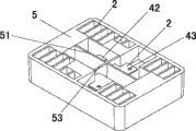
图3为本发明提供的太阳电池组件用接线盒的一个实施例的示意图。如图3所示,该实施例的接线盒包括盒体5,盒体5中设置有散热单元2及设置在盒体5中的至少两个互相没有直接电性连接的控制电路,每个控制电路用于同太阳电池组件中的支路并联。每个控制电路包括二极管(未示出)和与二极管管脚相电连接的用于与汇流条连接的导电体,导电体包括第一导电体41、第二导电体42,第一、第二导电体41、42与二极管为一体成型结构。上述的接线盒中,二极管(未示出)、绝缘导热介质及散热单元2可以一体注塑于所述盒体5中,这样可以消除接线盒安装过程中对二极管造成的损害,从而提高接线盒的可靠性,也更有利于接线盒中二极管的散热;散热单元2与盒体5紧密连接或者与盒体5为不同材料且一体成型,例如为金属和塑料的一体成型。在本实施例中,盒体5设置在散热单元2的外围。优选的,在盒体5中各控制电路之间设置隔板51,以防止各控制电路的二极管之间产生高压电弧,从而保护二极管,还可以在二极管的两管脚之间设有防止汇流条搭接的隔板53。Fig. 3 is a schematic diagram of an embodiment of a junction box for a solar cell module provided by the present invention. As shown in Figure 3, the junction box of this embodiment includes a
该实施例的太阳电池组件用接线盒,包括了至少两个控制电路,每个控制电路分别包含一个旁路二极管,因此一个接线盒可以保护至少两个与旁路二极管并联的太阳电池组件的支路,减少了系统的成本。旁路二极管通过绝缘导热性好的材料制成的连接部件与散热性好的散热部件连接,且散热部件与盒体紧密连接或一体成型,因此可以安全且快速的散去旁路二极管产生的热量,有效防止因温度过高而导致旁路二极管的损坏,从而保证太阳电池组件不会因温度过高而损坏;二极管和绝缘散热介质部分与散热器部分通过散热胶结合在一起,使得两者更加贴合,热阻小,利于散热,从根本上提高了二极管的散热能力,把集成了二极管、绝缘导热介质和散热器的部件注塑到盒体部分,这样做消除了在接线盒组装操作过程中对二极管的伤害,另外由于二极管、绝缘导热介质和散热器的部件与散热胶贴合得很好,更加有利于通过散热胶对二极管散热,且散热单元的大部分都暴露在空气中,空气对流使得散热片的功能得到最大限度的发挥,使得接线盒的散热能力大大提高。The solar cell assembly junction box of this embodiment includes at least two control circuits, and each control circuit includes a bypass diode, so one junction box can protect at least two solar cell assembly branches connected in parallel with the bypass diodes. way, reducing the cost of the system. The bypass diode is connected to the heat dissipation part with good heat dissipation through the connection part made of a material with good insulation and thermal conductivity, and the heat dissipation part is closely connected or integrally formed with the box body, so the heat generated by the bypass diode can be dissipated safely and quickly , effectively prevent the bypass diode from being damaged due to high temperature, so as to ensure that the solar cell module will not be damaged due to high temperature; the diode and the insulating heat dissipation medium part are combined with the heat sink part through heat dissipation glue, making the two more efficient Bonding, small thermal resistance, good for heat dissipation, fundamentally improves the heat dissipation capacity of the diode, and injects the parts integrating the diode, insulating and heat-conducting medium and the heat sink into the box body, which eliminates the need for heat dissipation during the assembly operation of the junction box. Damage to the diode, in addition, because the diode, the insulating and heat-conducting medium and the parts of the radiator are well bonded to the heat dissipation glue, it is more conducive to the heat dissipation of the diode through the heat dissipation glue, and most of the heat dissipation unit is exposed to the air, and the air convection The function of the heat sink is maximized, and the heat dissipation capacity of the junction box is greatly improved.
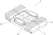
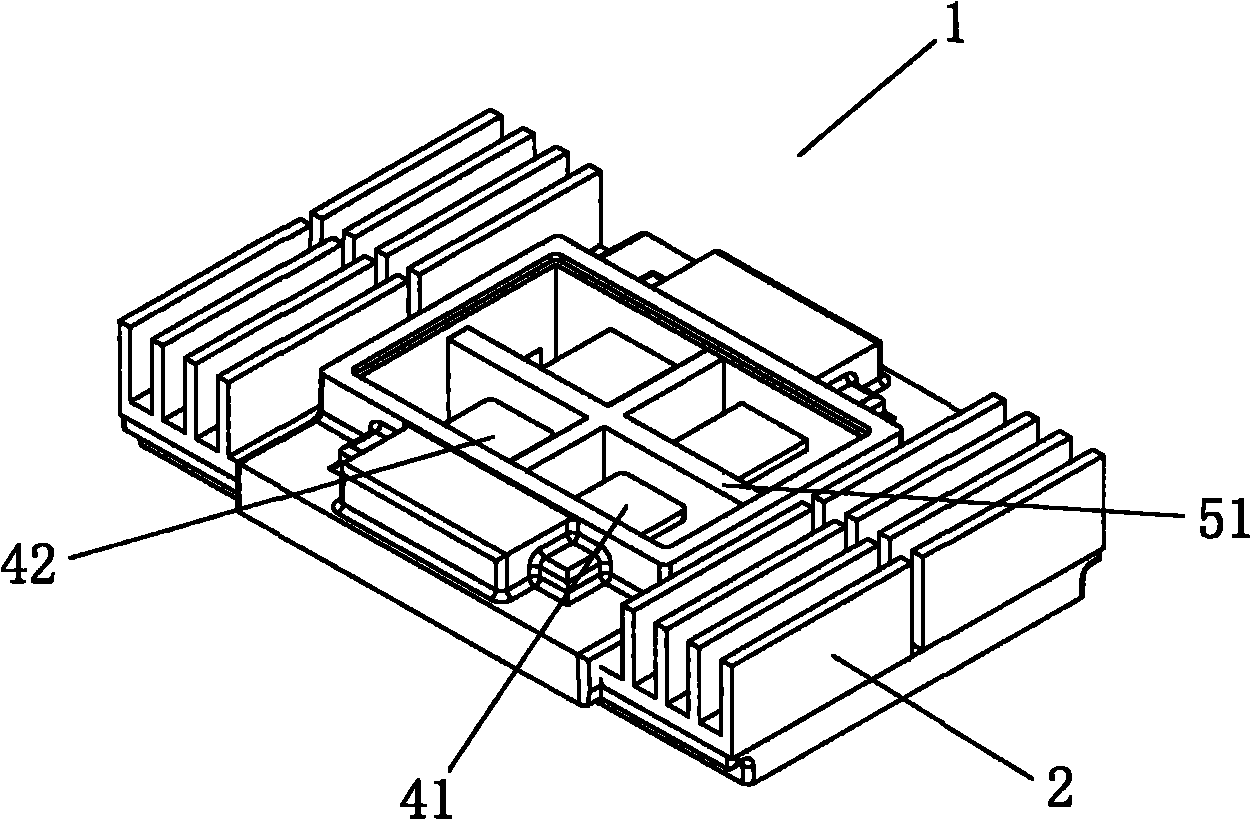
图4为本发明提供的太阳电池组件用接线盒的另一个实施例的示意图;图5为图4所示接线盒盖上盒盖之后的示意图。如图4、图5所示,该实施例的接线盒1包括盒体5,与图3所示的接线盒不同的是盒体5没有设置在散热单元2的外围,而是仅设置在散热单元2的中心部位,即散热单元2的散热栅板22设置在盒体5的外围,这样使散热单元2更多地暴露于空气中,更加提高了接线盒1的散热性。优选的,在盒体5中各控制电路之间设置隔板51,以防止各控制电路的二极管之间产生高压电弧,从而保护二极管,还可以在二极管的两管脚之间设有防止汇流条搭接的隔板(未示出)。Fig. 4 is a schematic diagram of another embodiment of the junction box for solar cell modules provided by the present invention; Fig. 5 is a schematic diagram of the junction box shown in Fig. 4 after the box cover is put on. As shown in Figures 4 and 5, the
如图5所示,上述接线盒还可以包括盒盖52,盒盖52构造为仅密封盒体5中设置有所述导电体的区域,即,使散热单元2尽可能多地暴露于空气中,以利于接线盒的散热。可使散热单元2的散热栅板22和/或部分散热底板21暴露于空气中,这样更有利于接线盒中二极管的散热,另盒盖52也可用于标记图形及文字符号等;另外,在盒体5和盒盖52之间可设有用于增加接线盒1的密封性能的密封圈(未示出),可置于盒体5或盒盖52上的密封圈槽(未图示)中;盒体5与盒盖52可通过卡扣结构(未示出)等公知的连接方式进行密封连接,其中盒体5与散热单元2还可以为一体成型的。As shown in Fig. 5, the above-mentioned junction box may further include a
图6为本发明提供的太阳电池组件用接线盒的另一个实施例的示意图;图7为图6所示接线盒盖上盒盖之后的示意图,如图6及图7所示,本实施例中,接线盒1′与上述接线盒1相似,在每个控制电路中,仅包括一个导电体与二极管(未示出)管脚相电连接为一体或为一体成型结构。接线盒1′的盒体5上设置有电缆连接件,电缆连接件包括电缆线74、螺母73及公头(插头),其中公头按照本领域的公知常识与电缆线74连接,本实施例的电缆连接件是通过螺母73设置在盒体5上并与盒体5内的一个控制电路电连接,即,公头分别与接线盒中的第一导电体和第二导电体相电连接,在本发明可选的实施例中,电缆连接件也可以通过其他的方式与盒体5连接。优选的,在盒体5中各控制电路之间设置隔板51,以防止各控制电路的二极管之间产生高压电弧,从而保护二极管,还可以在二极管的两管脚之间设有防止汇流条搭接的隔板(未示出)。Fig. 6 is the schematic diagram of another embodiment of the junction box for solar cell assembly provided by the present invention; Fig. 7 is the schematic diagram after the junction box shown in Fig. 6 is covered with a box cover, as shown in Fig. 6 and Fig. Among them, the junction box 1' is similar to the
图8为本发明提供的太阳电池组件用接线盒的另一个实施例的示意图;图9为图8所示接线盒盖上盒盖之后的示意图,如图8及图9所示,本实施例中,太阳电池组件用接线盒1″与上述接线盒1相似,接线盒1″的盒体5上设置有包括公头71及母头72的电缆连接件,电缆连接件与盒体5内的一个控制电路电连接。优选的,在盒体5中各控制电路之间设置隔板51,以防止各控制电路的二极管之间产生高压电弧,从而保护二极管,还可以在二极管的两管脚之间设有防止汇流条搭接的隔板(未示出)。Fig. 8 is a schematic diagram of another embodiment of a junction box for solar cell modules provided by the present invention; Fig. 9 is a schematic diagram after the junction box shown in Fig. 8 is covered with a cover, as shown in Fig. 8 and Fig. 9, the present embodiment Among them, the solar cell
图6、图7所示的接线盒1′与图8、图9所示的接线盒1″可以通过电缆连接件包括的公头与母头相互电连接,方法简便,不仅可以节约大量的电缆连接线,接线盒之间的连接更加可靠、方便,尤其可以提高系统安装效率。而图4、图5所示的接线盒1与图6、图7所示的接线盒1′及图8、图9所示的接线盒1″之间可以利用太阳电池组件内的汇流条进行电连接。The junction box 1' shown in Figure 6 and Figure 7 and the
图10为本发明的太阳电池组件的一种电路连接示意图,图11为本发明的太阳电池组件用接线盒安装在图10所示的太阳电池组件上的示意图。如图10、图11所示,该实施例的太阳电池组件6安装有上述的接线盒,且接线盒安装在太阳电池组件6的中部位置,由于图示的太阳电池组件6分为6个支路,且图示的每个接线盒包括两个控制电路2,因此太阳电池组件6上设置了3个接线盒,但此仅为示例,不作为对本发明的限定。每个接线盒中的两个控制电路分别与太阳电池组件6的位置相对且两个互相没有直接电连接的支路通过汇流条61并联,三个接线盒优选地分别为接线盒1、1′、1″,且接线盒1设置在接线盒1′、1″之间,三个接线盒之间可以利用太阳电池组件6上的汇流条61进行电连接,设置有接线盒1、1′、1″的太阳电池组件之间进行电连接时,优选地处于相邻位置的两个太阳电池组件6相互电连接的接线盒分别为接线盒1′及1″,这样可以通过接线盒1′及1″的电缆连接件快速、可靠的将多个太阳电池组件6连接在一起,既可以节约连接电缆而且因为使用的电缆线较短且电缆连接件与接线盒为一体的而无需将电缆线进行固定,从而提高了系统安装效率和降低系统成本。FIG. 10 is a schematic diagram of a circuit connection of a solar cell module of the present invention, and FIG. 11 is a schematic diagram of a junction box for a solar cell module of the present invention installed on the solar cell module shown in FIG. 10 . As shown in Fig. 10 and Fig. 11, the solar cell assembly 6 of this embodiment is equipped with the above-mentioned junction box, and the junction box is installed in the middle of the solar cell assembly 6, since the illustrated solar cell assembly 6 is divided into six branches road, and each junction box shown in the figure includes two
总之,以上所述仅为本发明的实施例,并非用于限定本发明的保护范围,而是用于说明本发明。凡在本发明的精神和原则之内,所作的任何修改、等同替换、改进等,均应包含在本发明的保护范围之内。In a word, the above descriptions are only examples of the present invention, not for limiting the protection scope of the present invention, but for illustrating the present invention. Any modifications, equivalent replacements, improvements, etc. made within the spirit and principles of the present invention shall be included within the protection scope of the present invention.
Claims (28)
Priority Applications (1)
| Application Number | Priority Date | Filing Date | Title |
|---|---|---|---|
| CN201010118329XA CN101789572B (en) | 2010-03-03 | 2010-03-03 | Junction box for solar cell module |
Applications Claiming Priority (1)
| Application Number | Priority Date | Filing Date | Title |
|---|---|---|---|
| CN201010118329XA CN101789572B (en) | 2010-03-03 | 2010-03-03 | Junction box for solar cell module |
Publications (2)
| Publication Number | Publication Date |
|---|---|
| CN101789572A true CN101789572A (en) | 2010-07-28 |
| CN101789572B CN101789572B (en) | 2012-07-04 |
Family
ID=42532680
Family Applications (1)
| Application Number | Title | Priority Date | Filing Date |
|---|---|---|---|
| CN201010118329XA Active CN101789572B (en) | 2010-03-03 | 2010-03-03 | Junction box for solar cell module |
Country Status (1)
| Country | Link |
|---|---|
| CN (1) | CN101789572B (en) |
Cited By (10)
| Publication number | Priority date | Publication date | Assignee | Title |
|---|---|---|---|---|
| WO2011047543A1 (en) * | 2009-10-22 | 2011-04-28 | 无锡尚德太阳能电力有限公司 | Junction box for solar battery module |
| CN102169915A (en) * | 2011-04-30 | 2011-08-31 | 常州天合光能有限公司 | Photovoltaic assembly having junction box arranged in middle |
| CN102646739A (en) * | 2011-02-16 | 2012-08-22 | 台达电子工业股份有限公司 | Terminal box |
| CN102694354A (en) * | 2011-03-25 | 2012-09-26 | 李浩日 | Junction box and manufacturing method thereof |
| CN102723391A (en) * | 2012-05-25 | 2012-10-10 | 高密星合电子有限公司 | Photovoltaic wiring device |
| CN102945878A (en) * | 2012-12-07 | 2013-02-27 | 常熟市福莱德连接器科技有限公司 | Photovoltaic wiring box |
| CN107547041A (en) * | 2017-09-01 | 2018-01-05 | 宁波明禾新能源科技有限公司 | A kind of sun-proof type solar junction box |
| CN108540086A (en) * | 2018-01-18 | 2018-09-14 | 浙江人和光伏科技有限公司 | A kind of conductive module of solar battery connecting box |
| WO2019114021A1 (en) * | 2017-12-12 | 2019-06-20 | 北京创昱科技有限公司 | Diode mounting tool and diode and solar cell module integrated device |
| CN111682473A (en) * | 2020-07-23 | 2020-09-18 | 常熟市福莱德连接器科技有限公司 | A conductor junction box with a miniature heat sink |
Citations (4)
| Publication number | Priority date | Publication date | Assignee | Title |
|---|---|---|---|---|
| US20040177987A1 (en) * | 2003-01-08 | 2004-09-16 | Sumitomo Wiring Systems, Ltd. | Terminal box device for a solar cell module and a connecting method for a terminal box device |
| CN200980053Y (en) * | 2006-12-08 | 2007-11-21 | 孙月静 | The connection box of solar photovoltaic generating components |
| CN201038171Y (en) * | 2007-03-06 | 2008-03-19 | 松赞实业股份有限公司 | Aluminum alloy solar module junction box |
| CN201138665Y (en) * | 2007-12-19 | 2008-10-22 | 朱梅芳 | Wiring box of solar photovoltaic energy production component |
-
2010
- 2010-03-03 CN CN201010118329XA patent/CN101789572B/en active Active
Patent Citations (4)
| Publication number | Priority date | Publication date | Assignee | Title |
|---|---|---|---|---|
| US20040177987A1 (en) * | 2003-01-08 | 2004-09-16 | Sumitomo Wiring Systems, Ltd. | Terminal box device for a solar cell module and a connecting method for a terminal box device |
| CN200980053Y (en) * | 2006-12-08 | 2007-11-21 | 孙月静 | The connection box of solar photovoltaic generating components |
| CN201038171Y (en) * | 2007-03-06 | 2008-03-19 | 松赞实业股份有限公司 | Aluminum alloy solar module junction box |
| CN201138665Y (en) * | 2007-12-19 | 2008-10-22 | 朱梅芳 | Wiring box of solar photovoltaic energy production component |
Cited By (10)
| Publication number | Priority date | Publication date | Assignee | Title |
|---|---|---|---|---|
| WO2011047543A1 (en) * | 2009-10-22 | 2011-04-28 | 无锡尚德太阳能电力有限公司 | Junction box for solar battery module |
| CN102646739A (en) * | 2011-02-16 | 2012-08-22 | 台达电子工业股份有限公司 | Terminal box |
| CN102694354A (en) * | 2011-03-25 | 2012-09-26 | 李浩日 | Junction box and manufacturing method thereof |
| CN102169915A (en) * | 2011-04-30 | 2011-08-31 | 常州天合光能有限公司 | Photovoltaic assembly having junction box arranged in middle |
| CN102723391A (en) * | 2012-05-25 | 2012-10-10 | 高密星合电子有限公司 | Photovoltaic wiring device |
| CN102945878A (en) * | 2012-12-07 | 2013-02-27 | 常熟市福莱德连接器科技有限公司 | Photovoltaic wiring box |
| CN107547041A (en) * | 2017-09-01 | 2018-01-05 | 宁波明禾新能源科技有限公司 | A kind of sun-proof type solar junction box |
| WO2019114021A1 (en) * | 2017-12-12 | 2019-06-20 | 北京创昱科技有限公司 | Diode mounting tool and diode and solar cell module integrated device |
| CN108540086A (en) * | 2018-01-18 | 2018-09-14 | 浙江人和光伏科技有限公司 | A kind of conductive module of solar battery connecting box |
| CN111682473A (en) * | 2020-07-23 | 2020-09-18 | 常熟市福莱德连接器科技有限公司 | A conductor junction box with a miniature heat sink |
Also Published As
| Publication number | Publication date |
|---|---|
| CN101789572B (en) | 2012-07-04 |
Similar Documents
| Publication | Publication Date | Title |
|---|---|---|
| CN101789572B (en) | Junction box for solar cell module | |
| US11641098B1 (en) | Cooling system for busbars | |
| AU2012200866B2 (en) | Photovoltaic junction box | |
| CN106299223B (en) | battery module | |
| CN104995758A (en) | battery case | |
| CN104362972A (en) | Split type photovoltaic terminal box with cable protection structure | |
| JP5777580B2 (en) | Terminal box | |
| CN204013385U (en) | A kind of photovoltaic junction box bypass diode circuit module of device | |
| CN102420544A (en) | Integral-type injection molding junction box and manufacturing method thereof | |
| JP2005150277A (en) | Terminal box for solar cell module | |
| CN102044991B (en) | Junction box for solar cell module | |
| CN204119148U (en) | A kind of external photovoltaic counnter attack device and photovoltaic plant convergence system | |
| CN203192820U (en) | Efficient heat dissipation solar photovoltaic junction box | |
| WO2011116557A1 (en) | Solar photovoltaic component, terminal box used thereof and diode structure used threrof | |
| US20140256174A1 (en) | Terminal box for solar cell | |
| CN214900790U (en) | Split type terminal box of solar photovoltaic module | |
| CN206370453U (en) | Portable pump lithium battery group | |
| CN211429264U (en) | Photovoltaic junction box | |
| CN103532490B (en) | Photovoltaic power source management module | |
| CN111540854B (en) | High-energy-density battery system and vehicle | |
| CN210839468U (en) | Photovoltaic module | |
| CN108566160B (en) | Intelligent junction box with multichannel power management module | |
| CN202534666U (en) | Solar energy cell conjunction box | |
| CN219304792U (en) | High-power intelligent photovoltaic junction box and wiring terminal thereof | |
| CN200950438Y (en) | Junction box of a solar cell module |
Legal Events
| Date | Code | Title | Description |
|---|---|---|---|
| C06 | Publication | ||
| PB01 | Publication | ||
| C10 | Entry into substantive examination | ||
| SE01 | Entry into force of request for substantive examination | ||
| C14 | Grant of patent or utility model | ||
| GR01 | Patent grant |