CN101788042A - Symmetrical toggle rod pressure transmission mechanism - Google Patents
Symmetrical toggle rod pressure transmission mechanism Download PDFInfo
- Publication number
- CN101788042A CN101788042A CN 201010114197 CN201010114197A CN101788042A CN 101788042 A CN101788042 A CN 101788042A CN 201010114197 CN201010114197 CN 201010114197 CN 201010114197 A CN201010114197 A CN 201010114197A CN 101788042 A CN101788042 A CN 101788042A
- Authority
- CN
- China
- Prior art keywords
- hinge
- pressure transmission
- transmission mechanism
- nut
- screw rod
- Prior art date
- Legal status (The legal status is an assumption and is not a legal conclusion. Google has not performed a legal analysis and makes no representation as to the accuracy of the status listed.)
- Pending
Links
Images


Classifications
-
- B—PERFORMING OPERATIONS; TRANSPORTING
- B30—PRESSES
- B30B—PRESSES IN GENERAL
- B30B1/00—Presses, using a press ram, characterised by the features of the drive therefor, pressure being transmitted directly, or through simple thrust or tension members only, to the press ram or platen
- B30B1/10—Presses, using a press ram, characterised by the features of the drive therefor, pressure being transmitted directly, or through simple thrust or tension members only, to the press ram or platen by toggle mechanism
- B30B1/106—Presses, using a press ram, characterised by the features of the drive therefor, pressure being transmitted directly, or through simple thrust or tension members only, to the press ram or platen by toggle mechanism operated by another toggle mechanism
Abstract
The invention relates to a symmetrical toggle rod pressure transmission mechanism belonging to the field of connecting bar transmission mechanisms. The toggle rod pressure transmission mechanism comprises toggle rod mechanisms, a drive block, a slide block and a rack, wherein two toggle rod mechanisms are symmetrically arranged at both sides of an axis of a drive rod positioned in the center of the mechanism; each toggle rod mechanism comprises an upper toggle plate, a lower toggle rod and a middle connecting bar, wherein the upper toggle plate is respectively connected with the lower toggle rod, the middle connecting bar and the rack through a toggle rod hinge, a connection hinge and an upper beam hinge, the other end of the lower toggle rod is connected with the slice block through a slide block hinge, and the other end of the middle connecting bar is connected with a driving slide block through a driving hinge; and a segment taking the axle centers of the two connection hinges as endpoints is always intersected with a straight line passing through the axle center of the upper beam hinge and the axle center of the toggle rod hinge positioned at the same side with the upper beam hinge. Compared with the traditional symmetrical six-bar mechanism, the invention has good force-increasing effect, relative uncomplicated stress of a load-bearing shaft, difficult breakage, low total height of the mechanism, and the like.
Description
Technical field
The invention belongs to jointed gear unit, be specifically related to a kind of pressure drive mechanism.
Background technique
The symmetry six link presses product of (net wild (Wuhan) High Seience Technology Co., Ltd.) are the equipment of popular recently plastic working.It is with respect to other traditional pressure mechanism, for example crank-connecting rod transmission type press machine is (referring to "<crank press ", He Deyu, China Machine Press, 1987), toggle link transmission type press machine is (referring to " optimal design of mechanical press toggle link driving mechanism ", Zhang Yuantong, Zhu Denglin, " machinery and electronics ", 2008 (1), 10~12 pages), hydraulic driven press machine (referring to " design of hydraulic press and application ", Yu Xinlu, China Machine Press) and power screw formula press machine (referring to the J58K series numerical control electric screw press of Wuhan Xinweiqi Technology Co., Ltd.) have certain advantage.Be embodied in: 1, the lateral force of slide block is null under the situation of no unbalance loading, has so both guaranteed the working life of guide rail, has also improved formed precision.2, the reinforcement function of symmetrical six bar mechanism is more obvious, has reduced motor driving moment.But there are the following problems for symmetrical six link lever press driving mechanisms: 1, the bracket height size is big, occupies height space, needs tall and big delivery room, thereby has increased the construction cost of factory building; 2, be that speed is slow in idle stroke, cause inefficiency; 3, effectively the reinforcement stroke is short, causes this mechanism's operating range short.
The invention provides a kind of symmetrical toggle lever pressure transmission mechanism, reinforcement multiple, effective reinforcement stroke obviously are better than symmetrical six bar mechanism; And when having identical ram travel, mechanism of the present invention total height is lower by about 11% than symmetrical six bar mechanism, more can adapt to little factory building, reduces construction cost; Under the situation of no unbalance loading, there is not the slide block lateral force simultaneously yet; No-load speed is higher than symmetrical six bar mechanism.
Summary of the invention
For realizing purpose of the present invention, the concrete technological scheme of employing is:
A kind of symmetrical toggle lever pressure transmission mechanism, comprise slide block, driving source, two elbow-bar mechanism that are positioned at the driveshaft of central authorities of mechanism and are symmetrically arranged in above-mentioned driveshaft axis both sides, described elbow-bar mechanism comprises bracket, lower elbow lever and intermediate connecting rod, last bracket is by the toggle link hinge, connect hinge and upper beam hinge respectively with lower elbow lever one end, intermediate connecting rod one end links to each other with frame, the lower elbow lever the other end is connected with slide block by the slide block hinge, the intermediate connecting rod the other end is connected with driving sliding block by driving hinge
It is characterized in that in the entire work process of mechanism, the line segment that is end points with two described connection hinge axle center remains with the straight line in the toggle link hinge axle center of passing through described upper beam hinge axle center and its homonymy crossing.
In the elbow-bar mechanism of the present invention, last bracket, lower elbow lever and intermediate connecting rod all are at least one.
The present invention connects auxiliary rod between described upper beam hinge and toggle link hinge.
Driving source of the present invention is a motor, and described driveshaft is made up of screw rod and nut, and nut and screw rod constitute the ball screw structure, and motor is connected with screw rod, and nut is fixed on the driving block, the promotion driving block thereby the rotation drive nut by screw rod moves up and down.
Driving source of the present invention is a motor, and described driveshaft is made up of screw rod and nut, and nut and screw rod constitute the ball screw structure, and motor is connected with nut, and screw rod is fixed on the driving block, rotates the drive screw rod by nut and moves up and down, thereby promote driving block.
Be connected by worm and gear and/or gear train between motor of the present invention and screw rod or the nut.
Driving source of the present invention is an oil hydraulic cylinder, and driveshaft is the piston rod of oil hydraulic cylinder, and the termination of piston rod is fixed on the driving block.
Upward bracket of the present invention is set square triangle, circular plate or support.
A kind of press machine comprises the described symmetrical toggle lever pressure transmission mechanism of one of frame, guide rail, worktable and technique scheme.
A kind of injection machine comprises the described symmetrical toggle lever pressure transmission mechanism of one of frame, guide rail, worktable and technique scheme.
Drive characteristics of the present invention is: main driveshaft drives driving block and moves back and forth along main driveshaft axis, make the connection hinge of intermediate connecting rod drive go up the bracket bar and swing, make the toggle link hinge of bracket drive the lower elbow lever promotion slide block hinge that acts synergistically simultaneously slide block is moved up and down along vertical track.
The present invention utilizes driving block hinged with an end of the intermediate connecting rod of symmetry, the last bracket of the other end of intermediate connecting rod and symmetric arrangement is hinged, last bracket is hinged with the lower elbow lever of symmetry by the toggle link hinge, common formation boosting mechanism, vertically drive driving block with driveshaft, slide block is pumped as straight line in the vertical line direction, constitute press machine jointly with this pressure drive mechanism and other auxiliary device, slide block is to the guide rail non-lateral pressure, and the power of can reducing friction significantly improves transmission efficiency.Owing to use toggle link reinforcement and set square triangle reinforcement principle, use press machine of the present invention to compare with traditional crank connecting rod transmission type press machine, toggle link transmission type press machine, under identical nominal operation load, can significantly reduce input power; Load rating working stroke scope is bigger; When using motor to make driving source, the may command slide block is done variable motion, and increases work efficiency.The existing mechanical press of press machine that constitutes with the present invention fast, location and the high characteristic of repetitive positioning accuracy, the long Pressure characteristics of load rating working stroke of hydraulic press is arranged again.
When the present invention adopts AC motor to drive, energy that can only output needs when work, for intermittently used machines such as press machine, at upper and lower material consumed energy not in the time, so than general general driving mode, energy-conservation substantially more than 50%.Can utilize the control characteristic of motor, the control slide block is done variable motion, increases work efficiency.
The characteristic of the existing fluid drive mechanism of the present invention has the characteristic of crank-connecting rod transmission, toggle link driving mechanism again, has boosting function; Can be in most of stroke range of slide block movement with load rating work, slide block equals zero to the lateral force of guide rail in the total travel scope of motion, and slide block can variable motion, can pressurize at lower dead centre; Be applicable to the shaping of metal, nonmetal and special material.
Description of drawings
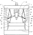
Fig. 1 is the structural representation of the embodiment of the invention one;
Fig. 2 is the structural representation of the embodiment of the invention two;
Fig. 3 is the structural representation of the embodiment of the invention three;
Fig. 4 is transmission principle figure of the present invention;
Fig. 5 is the comparison diagram of the reinforcement effect of the present invention and symmetrical six bar mechanism;
Embodiment
Below in conjunction with drawings and Examples pressure drive mechanism of the present invention is further specified.
Embodiment one
As shown in Figure 1, be fixed with the first upper beam hinge 6A on the bracket 3A on first, the first toggle link hinge 7A is connected hinge 8A with first, bracket 3A is connected with frame 11 by the first upper beam hinge 6A on first; The first lower elbow lever 4A, one end is connected with bracket 3A on first by the first toggle link hinge 7A, and the first lower elbow lever 4A the other end is connected with slide block 10 by the first slide block hinge 9A; The end of the first intermediate connecting rod 2A connects hinge 8A by first and is connected with bracket 3A on first, and the other end of the first intermediate connecting rod 2A drives hinge 5A by first and is connected with driving block 1.
Symmetrically, be fixed with the second upper beam hinge 6B on the bracket 3B on second, the second toggle link hinge 7B is connected hinge 8B with second, bracket 3B is connected with frame 11 by the second upper beam hinge 6B on second; The second lower elbow lever 4B, one end is connected with bracket 3B on second by the second toggle link hinge 7B, and the second lower elbow lever 4B the other end is connected with slide block 10 by the second slide block hinge 9B; The end of the second intermediate connecting rod 2B connects hinge 8B by second and is connected with bracket 3B on second, and the other end of the second intermediate connecting rod 2B drives hinge 5B by second and is connected with driving block 1.
Motor 14 is installed on the support 11, and motor 14 is connected with screw rod 13 by shaft joint 12, and the nut on the screw rod 13 is fixed on driving block 1, and motor 14 can drive in positive and negative two directions rotation, can control output torque and rotating speed.
Screw rod 13 axis and driving block 1 central lines, screw rod 13 lower ends are fixed on the screw rod fixing device 16;
Fig. 4 is transmission principle figure of the present invention, driveshaft can move up and down along the driveshaft axis, driving driving block 1 moves along the direction of driveshaft axis, the first intermediate connecting rod 2A in left side is swung by bracket 3A in the first connection hinge 8A drive first, thereby the bracket 3A and the first lower elbow lever 4A synergy movement on first, the motion of mechanism on right side is just the same with the left side, is symmetrical.Mechanism's collaborative work of the left and right sides can move up and down slide block 1 stably, does not produce lateral pressure.
Under the driving of nut, driving block 1 moves along the axial direction of screw rod 13 is upper and lower together with nut; This moment, the first toggle link hinge 7A was connected hinge 8A under the constraint of bracket 3A on first with first, do left and right swing along two circular arc lines respectively, the second toggle link hinge 7B is connected hinge 8B under the constraint of bracket 3B on second with second, do left and right swing along two circular arc lines respectively, the first slide block hinge 9A and the second slide block hinge 9B then drive slide block 10 and move up and down along the vertical line direction.
On first on the bracket 3A and second bracket 3B by first be connected hinge 8A be connected with second hinge 8B drive do left and right swing in, can bear the load of transmitting up by the first lower elbow lever 4A and the second lower elbow lever 4B from slide block 10, and give frame 11 loading transfer.
In entire work process, being connected hinge 8B axle center with second with the first connection hinge 8A axle center is the line segment of end points, be crossing with the straight line by the first upper beam hinge 6A axle center and the first toggle link hinge 7A axle center, the while also intersects with the straight line that passes through the second crossbeam hinge 6B axle center and the second toggle link hinge 7B axle center.
Embodiment two
Be subjected to equilibrium of forces and stable operation for what guarantee mechanism, go up bracket, lower elbow lever and intermediate connecting rod quantity separately in the elbow-bar mechanism and can under hands-off situation, determine arbitrarily according to actual needs.In the present embodiment, the last bracket of single elbow-bar mechanism is 2, and lower elbow lever is 2, and intermediate connecting rod is 1.
As shown in Figure 2, increase bracket 3C on the 3rd in mechanism, the 3rd lower elbow lever 4C, bracket 3D on the 4th, the 4th lower elbow lever 4D, respectively with first on bracket 3A, the first lower elbow lever 4A, bracket 3B on second, before and after the second lower elbow lever 4B constitutes corresponding one group.Layout specific as follows: the first intermediate connecting rod 2A is hinged by bracket 3C on the bracket 3A and the 3rd on the first connection hinge 8A same first, the 3rd lower elbow lever 4C is hinged by bracket 3C on the 3rd toggle link hinge (failing to express in the drawings owing to interfere) and the 3rd, and slide block 10 is hinged with the first lower elbow lever 4A and the 3rd lower elbow lever 4C by the first slide block hinge 9A.The second intermediate connecting rod 2B is hinged by bracket 3D on the bracket 3B and the 4th on the second connection hinge 8B same second, the 4th lower elbow lever 4D is hinged by bracket 3D on the 4th toggle link hinge (failing to express in the drawings owing to interfere) and the 4th, and slide block 10 is hinged with the second lower elbow lever 4B and the 4th lower elbow lever 4D by the second slide block hinge 9B.
Other constituent element of present embodiment is identical with embodiment one, under the driving of motor 14, screw rod 13, makes slide block do upper and lower moving along the vertical line direction.
Embodiment three
As shown in Figure 3, in the present embodiment, for mechanism has better mechanical property, increased on embodiment two the basis first auxiliary on bracket 18A, the second auxiliary bracket 18B that goes up, the 3rd auxiliary bracket 18C that goes up, the 4th auxiliary bracket 18D that goes up, concrete layout is as follows: increase by first in the front side of the first lower elbow lever 4A and the second lower elbow lever 4B respectively and assist bracket 18A and second to assist bracket 18B, the rear side of the 3rd lower elbow lever 4C and the 4th lower elbow lever 4D increase respectively the 3rd auxiliary on bracket 18C and the 4th auxiliary on bracket 18D (failing to show) at this figure, the end of the first auxiliary upward bracket 18A is hinged by the first upper beam hinge 6A and frame 11, the other end is hinged with the first lower elbow lever 4A by the first toggle link hinge 7A, the end of the second auxiliary upward bracket 18B is hinged by the second upper beam hinge 6B and frame 11, the other end is hinged with the second lower elbow lever 4B by the second toggle link hinge 7B, the end of the 3rd auxiliary upward bracket 18C is hinged by the first upper beam hinge 6A and frame 11, the other end is hinged with the 3rd lower elbow lever 4C by the 3rd toggle link hinge 7C (not shown), the end of the 4th auxiliary upward bracket 18D is hinged by the second upper beam hinge 6B and frame 11, and the other end is hinged with the 4th lower elbow lever 4D by the 4th toggle link hinge 7D (not shown).
Other constituent element of present embodiment is identical with embodiment one, under the driving of motor 14, screw rod 13, makes slide block do upper and lower moving along the vertical line direction.
Driving source is a motor in the foregoing description, and driveshaft is made up of screw rod and nut, and nut and screw rod constitute the ball screw structure, and motor links by shaft joint and screw rod, and nut is fixed on the driving block; In addition, also can pass through worm and gear between motor and the screw rod, gear train and other mechanisms connect; In addition, motor also can drive nut and rotate, and drives screw rod and moves up and down, to promote driving block.The present invention can also adopt hydraulic system as driving source, and driveshaft is the piston rod of oil hydraulic cylinder, and the termination of piston rod is fixed on the driving block.
The present invention can be used for the press machine of plastic working, the present invention is installed on the custom-designed fuselage that has worktable 17, a guide rail 15 constitute press machine, will be fixed on the fuselage 11 with the hinged bearing of the first upper beam hinge 6A and the second upper beam hinge 6B.The effect of guide rail 15 is constraint slide blocks 10, and when making it eccentric load to occur in pressure processing, guide rail can retrain slide block and keep straight line motion, thereby guarantees machining accuracy.Mould is installed in bottom at slide block, at table top bed die is installed, and promptly can be used for the plastic workings such as punching press, pull and stretch, extruding, impression of material.
Be illustrated in figure 5 as when the present invention littler by 11% than the height of symmetrical six bar mechanism, under the identical situation of width, load reinforcement multiple---the stroke curve under equal motor torque drives of two structures.The total kilometres of two mechanisms all are 600 millimeters, and this figure has got nethermost 200 millimeters straight, and the high order end of abscissa is the lower dead centre of slide block.Dotted line is a curve of the present invention, and solid line is the curve of symmetrical six bar mechanism.Can find out obviously that from plotted curve the present invention obviously is being better than symmetrical six bar mechanism aspect the reinforcement effect.(it is in order to improve the readability of figure that curve is not signed in high order end, and in fact up to the transverse axis high order end, dotted line all will be higher than solid line, and gap is increasing)
Claims (10)
1. symmetrical toggle lever pressure transmission mechanism, comprise slide block, driving source, two elbow-bar mechanism that are positioned at the driveshaft of central authorities of mechanism and are symmetrically arranged in above-mentioned driveshaft axis both sides, described elbow-bar mechanism comprises bracket, lower elbow lever and intermediate connecting rod, last bracket is by the toggle link hinge, connect hinge and upper beam hinge respectively with lower elbow lever one end, intermediate connecting rod one end links to each other with frame, the lower elbow lever the other end is connected with slide block by the slide block hinge, the intermediate connecting rod the other end is connected with driving block by driving hinge
It is characterized in that, in the entire work process of mechanism, remain and intersect by described upper beam hinge axle center with straight line that this upper beam hinge axle center is in the toggle link hinge axle center of axis homonymy with two described connection hinge axle center line segment that is end points.
2. symmetrical toggle lever pressure transmission mechanism as claimed in claim 1 is characterized in that, in the described elbow-bar mechanism, last bracket, lower elbow lever and intermediate connecting rod all are at least one.
3. symmetrical toggle lever pressure transmission mechanism as claimed in claim 1 or 2 is characterized in that, connects auxiliary rod between described upper beam hinge and toggle link hinge.
4. as the described symmetrical toggle lever pressure transmission mechanism of one of claim 1-3, it is characterized in that, described driving source is a motor, described driveshaft is made up of screw rod and nut, nut and screw rod constitute the ball screw structure, motor is connected with screw rod, and nut is fixed on the driving block, moves up and down and promotes driving block thereby the rotation by screw rod drives nut.
5. as the described symmetrical toggle lever pressure transmission mechanism of one of claim 1-3, it is characterized in that, described driving source is a motor, described driveshaft is made up of screw rod and nut, nut and screw rod constitute the ball screw structure, and motor is connected with nut, and screw rod is fixed on the driving block, rotate the drive screw rod by nut and move up and down, thereby promote driving block.
6. as claim 4 or 5 described symmetrical toggle lever pressure transmission mechanisms, it is characterized in that, be connected by worm and gear and/or gear train between motor and screw rod or the nut.
7. as the described symmetrical toggle lever pressure transmission mechanism of one of claim 1-3, it is characterized in that described driving source is an oil hydraulic cylinder, driveshaft is the piston rod of oil hydraulic cylinder, and the termination of piston rod is fixed on the driving block.
8. as the described symmetrical toggle lever pressure transmission mechanism of one of claim 1-7, it is characterized in that: described upward bracket is set square triangle, circular plate or support.
9. a press machine comprises one of frame, guide rail, worktable and aforesaid right requirement 1-8 described symmetrical toggle lever pressure transmission mechanism.
10. an injection machine comprises one of frame, guide rail, worktable and aforesaid right requirement 1-8 described symmetrical toggle lever pressure transmission mechanism.
Priority Applications (1)
| Application Number | Priority Date | Filing Date | Title |
|---|---|---|---|
| CN 201010114197 CN101788042A (en) | 2010-02-10 | 2010-02-10 | Symmetrical toggle rod pressure transmission mechanism |
Applications Claiming Priority (1)
| Application Number | Priority Date | Filing Date | Title |
|---|---|---|---|
| CN 201010114197 CN101788042A (en) | 2010-02-10 | 2010-02-10 | Symmetrical toggle rod pressure transmission mechanism |
Publications (1)
| Publication Number | Publication Date |
|---|---|
| CN101788042A true CN101788042A (en) | 2010-07-28 |
Family
ID=42531373
Family Applications (1)
| Application Number | Title | Priority Date | Filing Date |
|---|---|---|---|
| CN 201010114197 Pending CN101788042A (en) | 2010-02-10 | 2010-02-10 | Symmetrical toggle rod pressure transmission mechanism |
Country Status (1)
| Country | Link |
|---|---|
| CN (1) | CN101788042A (en) |
Cited By (13)
| Publication number | Priority date | Publication date | Assignee | Title |
|---|---|---|---|---|
| CN102297252A (en) * | 2011-06-14 | 2011-12-28 | 西安交通大学 | Low-speed pressing mechanism with large force increasing stroke |
| CN102320153A (en) * | 2011-06-14 | 2012-01-18 | 西安交通大学 | A kind of transmission system that is applicable to large-tonnage AC servo forcing press |
| CN102350811A (en) * | 2011-07-15 | 2012-02-15 | 徐州海虹建筑工程机械有限公司 | Hinge transmission mechanism for press |
| CN104029408A (en) * | 2014-06-25 | 2014-09-10 | 西安交通大学 | Symmetric double-toggle-rod boosting high-speed press driven by cylindrical linear motor |
| CN105034427B (en) * | 2015-07-30 | 2016-08-24 | 西安交通大学 | It is arranged symmetrically with multi-end surface actuated by cams even number independence toggle rod-type servo |
| CN106192507A (en) * | 2016-08-29 | 2016-12-07 | 北京润拓工业技术有限公司 | Moment quick-fried straw treating device |
| CN106217833A (en) * | 2016-08-22 | 2016-12-14 | 昆山中德利机械科技有限公司 | A kind of cut assembly for plastic thermal molding equipment |
| CN106678315A (en) * | 2017-02-28 | 2017-05-17 | 合肥钱锋特殊胶粘制品有限公司 | Screw-nut pair driving mechanism and laminating machine |
| CN107575714A (en) * | 2017-08-13 | 2018-01-12 | 高飞 | A kind of environment-friendly engineering clamping device |
| CN107597989A (en) * | 2017-10-19 | 2018-01-19 | 上汽通用五菱汽车股份有限公司 | The main precompressed integral type taping machine of compact |
| CN108262452A (en) * | 2018-03-12 | 2018-07-10 | 苏州明志科技有限公司 | A kind of electricity drives molding core making machine |
| CN110039815A (en) * | 2018-12-26 | 2019-07-23 | 嘉兴大道锻造技术咨询有限公司 | A kind of double drive long stroke pressure mechanism |
| CN110355250A (en) * | 2019-08-12 | 2019-10-22 | 济南二机床集团有限公司 | A kind of toggle rod type machinery bound edge press machine |
Citations (5)
| Publication number | Priority date | Publication date | Assignee | Title |
|---|---|---|---|---|
| GB2011571A (en) * | 1977-12-15 | 1979-07-11 | Leinhaas W | A toggle-lever mechanism |
| US4302961A (en) * | 1979-06-23 | 1981-12-01 | Werner Leinhaas | Press or similar machine tool |
| CN2512581Y (en) * | 2001-10-29 | 2002-09-25 | 汕头市金园区明发机械有限公司 | Closing mold punching shear device of positive pressure forming machine |
| CN2910544Y (en) * | 2006-04-29 | 2007-06-13 | 苏州市佳达数控拉伸机械有限公司 | Hydraulic punch press |
| CN201714931U (en) * | 2010-02-10 | 2011-01-19 | 华中科技大学 | Symmetric-toggle-rod pressure transmission mechanism and pressure machine and injection molding machine comprising same |
-
2010
- 2010-02-10 CN CN 201010114197 patent/CN101788042A/en active Pending
Patent Citations (5)
| Publication number | Priority date | Publication date | Assignee | Title |
|---|---|---|---|---|
| GB2011571A (en) * | 1977-12-15 | 1979-07-11 | Leinhaas W | A toggle-lever mechanism |
| US4302961A (en) * | 1979-06-23 | 1981-12-01 | Werner Leinhaas | Press or similar machine tool |
| CN2512581Y (en) * | 2001-10-29 | 2002-09-25 | 汕头市金园区明发机械有限公司 | Closing mold punching shear device of positive pressure forming machine |
| CN2910544Y (en) * | 2006-04-29 | 2007-06-13 | 苏州市佳达数控拉伸机械有限公司 | Hydraulic punch press |
| CN201714931U (en) * | 2010-02-10 | 2011-01-19 | 华中科技大学 | Symmetric-toggle-rod pressure transmission mechanism and pressure machine and injection molding machine comprising same |
Cited By (14)
| Publication number | Priority date | Publication date | Assignee | Title |
|---|---|---|---|---|
| CN102320153A (en) * | 2011-06-14 | 2012-01-18 | 西安交通大学 | A kind of transmission system that is applicable to large-tonnage AC servo forcing press |
| CN102320153B (en) * | 2011-06-14 | 2014-11-05 | 西安交通大学 | Transmission system suitable for large-tonnage alternating current servo press |
| CN102297252A (en) * | 2011-06-14 | 2011-12-28 | 西安交通大学 | Low-speed pressing mechanism with large force increasing stroke |
| CN102350811A (en) * | 2011-07-15 | 2012-02-15 | 徐州海虹建筑工程机械有限公司 | Hinge transmission mechanism for press |
| CN104029408A (en) * | 2014-06-25 | 2014-09-10 | 西安交通大学 | Symmetric double-toggle-rod boosting high-speed press driven by cylindrical linear motor |
| CN105034427B (en) * | 2015-07-30 | 2016-08-24 | 西安交通大学 | It is arranged symmetrically with multi-end surface actuated by cams even number independence toggle rod-type servo |
| CN106217833A (en) * | 2016-08-22 | 2016-12-14 | 昆山中德利机械科技有限公司 | A kind of cut assembly for plastic thermal molding equipment |
| CN106192507A (en) * | 2016-08-29 | 2016-12-07 | 北京润拓工业技术有限公司 | Moment quick-fried straw treating device |
| CN106678315A (en) * | 2017-02-28 | 2017-05-17 | 合肥钱锋特殊胶粘制品有限公司 | Screw-nut pair driving mechanism and laminating machine |
| CN107575714A (en) * | 2017-08-13 | 2018-01-12 | 高飞 | A kind of environment-friendly engineering clamping device |
| CN107597989A (en) * | 2017-10-19 | 2018-01-19 | 上汽通用五菱汽车股份有限公司 | The main precompressed integral type taping machine of compact |
| CN108262452A (en) * | 2018-03-12 | 2018-07-10 | 苏州明志科技有限公司 | A kind of electricity drives molding core making machine |
| CN110039815A (en) * | 2018-12-26 | 2019-07-23 | 嘉兴大道锻造技术咨询有限公司 | A kind of double drive long stroke pressure mechanism |
| CN110355250A (en) * | 2019-08-12 | 2019-10-22 | 济南二机床集团有限公司 | A kind of toggle rod type machinery bound edge press machine |
Similar Documents
| Publication | Publication Date | Title |
|---|---|---|
| CN101788042A (en) | Symmetrical toggle rod pressure transmission mechanism | |
| CN101788043A (en) | Toggle lever pressure transmission mechanism | |
| CN201714931U (en) | Symmetric-toggle-rod pressure transmission mechanism and pressure machine and injection molding machine comprising same | |
| CN101788044A (en) | Pressure transmission mechanism of intermediate connecting plate | |
| CN101722664B (en) | Diagonally driven connecting rod pressure drive mechanism | |
| CN201687906U (en) | Toggle rod pressure transmission mechanism and pressure machine or injection molding machine comprising same | |
| CN201530140U (en) | Diagonal tension driven connecting rod pressure transmission mechanism | |
| CN207495909U (en) | A kind of multipurpose c-type double coloured plastic injection machine | |
| CN101799065A (en) | Multi-link pressure drive mechanism | |
| CN101863132B (en) | Mechanical servo drive main transmission device for digital turrent punch press | |
| CN203282712U (en) | Four-guide-pillar underdrive slider jacking type high-speed precision punch | |
| CN105298449A (en) | Novel screw-type oil pumping machine | |
| CN202753454U (en) | Double-screw press | |
| CN201296627Y (en) | Electrical screw-driven lifting platform | |
| CN201169063Y (en) | Crank press machine tool | |
| CN201687907U (en) | Middle connecting plate pressure transmission mechanism | |
| CN201714930U (en) | Multi-connecting-rod pressure transmission mechanism and press machine or injection molding machine comprising same | |
| CN201973192U (en) | Stroke amplifying mechanism | |
| CN206623165U (en) | A kind of cutting means of four-column cutting machine | |
| CN103418724B (en) | Twin screw electric screw press | |
| CN203019103U (en) | Strong five-shaft linkage head swaying mechanism of high-power electric main shaft | |
| CN101966923A (en) | Automatic pushing device | |
| CN210358659U (en) | High-speed heavy-load full-electric servo numerical control bending machine | |
| CN210358660U (en) | Multi-degree-of-freedom mechanical full-electric servo numerical control synchronous bending machine | |
| CN202398687U (en) | Single servo main transmission mechanism of numerical control turret punch press |
Legal Events
| Date | Code | Title | Description |
|---|---|---|---|
| C06 | Publication | ||
| PB01 | Publication | ||
| C10 | Entry into substantive examination | ||
| SE01 | Entry into force of request for substantive examination | ||
| C02 | Deemed withdrawal of patent application after publication (patent law 2001) | ||
| WD01 | Invention patent application deemed withdrawn after publication |
Open date: 20100728 |