CN101720418A - Method and apparatus for wheel alignment - Google Patents
Method and apparatus for wheel alignment Download PDFInfo
- Publication number
- CN101720418A CN101720418A CN200780053075A CN200780053075A CN101720418A CN 101720418 A CN101720418 A CN 101720418A CN 200780053075 A CN200780053075 A CN 200780053075A CN 200780053075 A CN200780053075 A CN 200780053075A CN 101720418 A CN101720418 A CN 101720418A
- Authority
- CN
- China
- Prior art keywords
- objective
- object component
- dimensional
- image
- wheel
- Prior art date
- Legal status (The legal status is an assumption and is not a legal conclusion. Google has not performed a legal analysis and makes no representation as to the accuracy of the status listed.)
- Pending
Links
Images


Classifications
-
- G—PHYSICS
- G01—MEASURING; TESTING
- G01B—MEASURING LENGTH, THICKNESS OR SIMILAR LINEAR DIMENSIONS; MEASURING ANGLES; MEASURING AREAS; MEASURING IRREGULARITIES OF SURFACES OR CONTOURS
- G01B11/00—Measuring arrangements characterised by the use of optical techniques
- G01B11/26—Measuring arrangements characterised by the use of optical techniques for measuring angles or tapers; for testing the alignment of axes
- G01B11/275—Measuring arrangements characterised by the use of optical techniques for measuring angles or tapers; for testing the alignment of axes for testing wheel alignment
- G01B11/2755—Measuring arrangements characterised by the use of optical techniques for measuring angles or tapers; for testing the alignment of axes for testing wheel alignment using photoelectric detection means
-
- G—PHYSICS
- G06—COMPUTING; CALCULATING OR COUNTING
- G06V—IMAGE OR VIDEO RECOGNITION OR UNDERSTANDING
- G06V10/00—Arrangements for image or video recognition or understanding
- G06V10/20—Image preprocessing
- G06V10/24—Aligning, centring, orientation detection or correction of the image
- G06V10/245—Aligning, centring, orientation detection or correction of the image by locating a pattern; Special marks for positioning
-
- G—PHYSICS
- G01—MEASURING; TESTING
- G01B—MEASURING LENGTH, THICKNESS OR SIMILAR LINEAR DIMENSIONS; MEASURING ANGLES; MEASURING AREAS; MEASURING IRREGULARITIES OF SURFACES OR CONTOURS
- G01B2210/00—Aspects not specifically covered by any group under G01B, e.g. of wheel alignment, caliper-like sensors
- G01B2210/10—Wheel alignment
- G01B2210/30—Reference markings, reflector, scale or other passive device
Abstract
A vehicle wheel alignment method and system is provided. A three- dimensional target is attached to a vehicle wheel known to be in alignment. The three-dimensional target has multiple target elements thereon, each of which has known geometric characteristics and 3D spatial relationship with one another.
Description
Background technology
Invention field
Invention given here relates to the method and apparatus of the location that is used for definite wheel.More specifically, the present invention relates to be used to utilize objective to determine the method and apparatus of the location of wheel.
Correlation technique
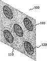
Usually know if wheel location each other is inaccurate, can cause the excessive wear or the irregular wear of tire and/or have influence on the manipulation and the stability of vehicle unfriendly.Therefore, need regularly to detect wheel to determine their whether accurate positionings.Traditionally, for determining the location of wheel, two dimension target is assembled on the wheel to be easy to carry out wheel alignment.Traditional two dimension target 100 is (prior art) as shown in fig. 1.Illustrated two dimension target 100 is plane targets 105, this plane target have with the known form space be arranged in a plurality of object components 120 on the target surface 110.Object component 120 can be made back reflection and target surface 110 can be non-reflection, so that suitable contrast to be provided.
Two dimension target 100 can be used for being convenient to carry out wheel alignment, and this is at United States Patent (USP) the 5th, 535, No. 522 and the 5th, 809, discloses in 658.Can use wheel alignment system (as United States Patent (USP) the 5th, 809, shown in Figure 9 in No. 658), video camera can be set in order to catch the two dimensional image of two dimension target 100 in this system, the object component 120 in this two dimensional image on the two dimension target 100 is visible.The particular characteristics relevant with object component can calculate by handling the two dimensional image of being caught, and these characteristics can be in order to the technology of using the wheel alignment field to know, the location of determining the wheel that two dimension target was attached to.
Be with a problem using two dimension target to be used for wheel alignment: the large-sized two dimension target of needs realizes that accurate wheel alignment is definite.
Summary of the invention
The invention solves realization, determine such as wheel alignment, accurately the demand measured.The invention provides a kind of improved system that utilizes three-dimensional (3D) target.
One aspect of the present invention relates to a kind of method that is used for determining the vehicle wheels location.Objective is attached on the wheel, has a plurality of object components on the wherein said objective, and each object component has specific known geometrical property and is configured in the 3d space according to specific known three-dimensional relationship relative to each other.Corresponding to a plurality of object component images of a plurality of object components, obtain detecting according to two dimension (2D) image by the objective that at least one video camera obtained.The location of wheel determines that based on the dimensional orientation of objective the three-dimensional relationship between this dimensional orientation based target part drawing picture and each object component is determined.
According to an embodiment, objective is attached on the wheel, have a plurality of object components on the wherein said objective, described object component has specific known geometrical property, also is configured in the 3d space according to known three-dimensional relationship relative to each other.Use at least one video camera to obtain the 2D image of objective.The 2D image of objective is in order to determine wheel alignment based on objective.
The other aspect of the present invention relates to a kind of system that is used for the location of definite vehicle wheels.Objective is used to be attached to wheel, has a plurality of object components on the wherein said objective, and described object component has specific known geometrical property, also is configured in the 3d space according to known three-dimensional relationship relative to each other.The 2D imaging system is set to be used to obtain the 2D image of described objective.Object component Characteristics Detection system according to the 2D image, detects a plurality of object component images corresponding to a plurality of object components.System is determined in wheel alignment, determines the location of wheel based on the dimensional orientation of objective, and this dimensional orientation is confirmed according to object component image that is detected and the three-dimensional relationship between each object component.
An embodiment according to the system of the location that is used for determining vehicle wheels has used the objective that can be attached on the wheel to be positioned.Have a plurality of object components on this objective, described object component has specific known geometrical property, also is configured in the 3d space according to known three-dimensional relationship relative to each other.Imaging system has at least one video camera, is constructed to be permeable to obtain the 2D image of objective.The directed definite system of wheel is used to utilize the 2D image of objective to determine the wheel orientation based on objective.
Another aspect of the present invention relates to a kind of method that is used to determine relate to the measurement of object.In one embodiment, objective is associated with this object.Have a plurality of object components on this objective, described object component has specific known geometrical property, also is configured in the 3d space according to known three-dimensional relationship relative to each other.Corresponding to a plurality of object component images of a plurality of object components, detected according to the 2D image of the objective that obtains by at least one video camera.Measurement about object determines that based on the dimensional orientation of objective the three-dimensional relationship between this dimensional orientation based target part drawing picture and each object component is determined.
Description of drawings
Invention requirement described here and/or explanation utilizes illustrative embodiments to be further detailed.With reference to the accompanying drawings these illustrative embodiments are described in detail.The determinate embodiment of these embodiment right and wrong, in these embodiments, whole structures like the same sequence number representation class in the view of accompanying drawings, and wherein:
Fig. 1 (prior art) shows the traditional two dimension target that is used in the wheel alignment;
Fig. 2 a shows the exemplary configurations of the objective of embodiment of the present invention to Fig. 2 e;
Fig. 3 has illustrated that the orientation of embodiment of the present invention determines the exemplary configurations of system;
Fig. 4 has described the geometric configuration of wheel alignment system of the use objective of embodiment of the present invention;
Fig. 5 has described the block diagram of exemplary wheel alignment system of the use objective of embodiment of the present invention;
Fig. 6 has described the block diagram of the exemplary 2D picture characteristics detection system of embodiment of the present invention; And
Fig. 7 is the process flow diagram that the use objective of embodiment of the present invention is used for the example process of definite wheel alignment.
Embodiment
The present invention relates to utilize be associated with object three-dimensional (3D) target, to carry out Flame Image Process, the method and system that carries out the measurement relevant with object by two dimension (2D) image to this 3D target.In some embodiments, this object is corresponding to wheel.The 3D target can be installed on the wheel, can carry out accurate wheel alignment.In some embodiments, this object is corresponding to hand-held device.The 3D target can be attached to or be associated with this device and measure can carry out loading height.In some embodiments, this object is corresponding to video camera.Can use the 3D target that attaches to or be associated with video camera, so that can carry out self calibration.Provide the details that to measure based on the 2D Flame Image Process about the 3D target below.
Fig. 2 a shows the exemplary configurations of the objective of embodiment of the present invention to Fig. 2 e.In Fig. 2 a, objective 200 comprises two or more solid face 201 and 202.Two faces 201 and 202 are by side of each face of alignment (seeing 200-1) located adjacent one another on the space, and their 200-2 that has a certain degree.On face 201, there are a plurality of object components 204, these object components are positioned on the face 201 according to some known space forms.Each object component all has some characteristics, such as shape, size or color; And these characteristics can be measured quantitatively.For example, as shown in Fig. 2 a, described object component is corresponding to filled circles.Flexible benchmark or the fid of often being called like this.Each this radius of a circle or barycenter can measure.In some embodiments, can be unified with the object component on the one side.In other embodiment, can be skimble-scamble with the object component on the one side.
Object component on each face is made visual perception.This can by object component and object component the surface of face between introduce contrast and realize.As shown in Fig. 2 a, it is darker that object component is made into the background surfaces (non-object component district) of specific surface 201.In some embodiments, object component can be made with different materials with background surfaces.For example, object component can be made back reflection, and background surfaces is made non-reflection.In other embodiment, background surfaces can be made of light color and make non-reflection than object component.
In Fig. 2 a, face 202 also has a plurality of object components 203.Object component on the face 202 can be similar to the mode of the object component on the face 201 and construct.For example, the object component on face 201 and the face 202 has similar characteristic, as shown in Fig. 2 a.In some embodiments, face 202 can be different from face 201.Object component on the face 202 can have different characteristics.In addition, the object component on the face 202 can be different layouts.
Fig. 2 b shows the different objective 205 according to an embodiment of the invention.Objective 205 total shapes roughly are similar to the rigidity cube with a plurality of, and these a plurality of faces comprise end face 206, front 207, the left side 208, bottom surface 209, the back side 210 and the right side 211.In a preferred embodiment, have one or more object components at least two faces.As in Fig. 2 b, seeing, four object component 210-a, 210-b, 210-c, 210-d are arranged on the back side of objective 205, and go up object component 209-a of existence in front.In this preferred implementation, the surface normal that has two faces of two dimension target element thereon has identical orientation.In some embodiments, the two dimension target element on two faces, to arrange when all visible pattern of target complete element when specific line of sight is observed.Although all element is visual, these object components can or cannot be overlapping.For making the target complete element visual, it is transparent that in two faces one can make, and as illustrated in fig. 2, wherein the front is transparent when observing rearwards when face in the past.
Fig. 2 c shows another exemplary configurations according to the objective 212 of embodiments of the present invention.As shown in Fig. 2 c, three-dimensional structure 214 is arranged as the face that physically is adjacent to 213 and both form specific spatial relationship.In some embodiments, the geometrical property of three-dimensional structure 214 is: have a surface thereon, this surperficial dimensional orientation is identical with the dimensional orientation on the surface 217 of face 213, and three-dimensional structure 214 is attached to the surface 217 of face 213.For example, the surface 215 among Fig. 2 c has the dimensional orientation identical with the surface 217 of face 213.
In such 3D structure, a plurality of two dimension target elements 216,217-a, 217-b, 217-c, 217-d are arranged on surface 217 and surperficial 215 according to ground, a shaping type space.In a preferred implementation, arrange the two dimension target element so that when target complete element when specific line of sight is observed as seen.Although the target complete element as seen, these object components can or cannot be overlapping.In a preferred implementation, sight line is perpendicular to surface 215 and surface 217.Fig. 2 c illustrates a kind of possible layout, wherein a plurality of object components around three-dimensional structure 214 be arranged on the face 213 and the single target arrangements of elements the surface 215 on.Should be understood that such explanation only is exemplary, they do not limit scope of the present invention.
Fig. 2 d shows another exemplary configurations according to the objective 220 of an embodiment of the invention.Objective 220 is corresponding to a kind of three-dimensional structure, and this three-dimensional structure has two-layer at least parallel plane in certain hollow space.As shown in Fig. 2 d, there is face parallel to each other 223,225 and 226, and is positioned at the diverse location place along axis perpendicular to the surface of these faces.One or more these parallel surfaces can be on a surface of three-dimensional structure 220.For example, parallel surface 225 and 226 is on the front surface 221 of 3D structure 220.
In some embodiments, all has the more than one object component of arranging according to a shaping type on each face.In the embodiment shown in Fig. 2 d, on face 223, there are four object component 223-a, 223-b, 223-c and 223-d that are arranged to rhombus.Two object component 229-a and 229-b are arranged on face 225, and two object component 230-a and 230-b are arranged on face 226.In some embodiments, the pattern of arranging object component is: when target complete element when specific line of sight is observed as seen.These object components can or cannot be overlapping.
Fig. 2 e shows the similar three-dimensional structure 231 with 220 (shown in Fig. 2 d), but has dissimilar object components on the not coplanar of structure.For example, as shown in Fig. 2 e, four object component 236-a, 236-b, 236-c and 236-d being installed on the front surface 232 of three-dimensional structure 231 are LED.In addition, Fig. 2 e difference of showing object component 235-a, 235-b on the face 233,235-c, 235-d, 235-e is arranged.
Fig. 3 shows thereon can carry out the example that orientation of the present invention is determined system.Directed definite system 300 comprises visual imaging system 302, and imaging system 302 has the video camera 310,312 a pair of fixing, the interval that is installed on the beam 314.Beam 314 has enough length and comes respectively video camera 310,312 to be positioned at the outside for the treatment of to be determined by orientation the vehicle of system's 300 imagings.In addition, beam 314 is positioned on the place 316 video camera 310,312 enough high, guaranteeing two destination apparatus 318,320 on the vehicle left side in the visual field of left side camera 110, and guarantee that two destination apparatus 322,321 on the vehicle right side are in the visual field of right side video camera 312.
Destination apparatus 318,320,322,324 is installed on each wheel 326,328,330,332 of motor vehicle, and each destination apparatus 318,320,322,324 all comprises attached peripheral device 338.Attached peripheral device 338 is attached to wheel 326,328,330,332 with destination apparatus 318,320,322,324.The name that licensed to people such as Borner on June 18th, 1991 is called the example that attached peripheral device has been described in No. 5024001 United States Patent (USP) of " Wheel Alignment Rim Clamp Claw ", is incorporated in this by merging.
In operation, in case directed determine that system 300 calibrated, as the 5th, 535, the 522 and the 5th, 724, illustrate in 743 United States Patent (USP)s, just can be to carriage 340 with vehicle traction, and if desired, vehicle is risen to suitable maintenance highly.In a single day destination apparatus 318,320,322,324 is attached on the wheel hub, makes target towards separately video camera 310,312 thereby then be directed then.
Usually known target device 318,320,322,324 with respect to, be attached with the position of wheel hub of the wheel 326,328,330,332 of these destination apparatus.In case destination apparatus 318,320,322,324 by imaging, just is rolled to wheel 326,328,330,332 another position and can obtains new image in a position.Use the image space of destination apparatus 318,320,322,324 in two positions, the physical location of wheel 326,328,330,332 and wheel axis and orientation can be calculated by visual imaging system 302.Although the distance between two positions changes, this distance is approximately 8 inches forward and backward usually.
Fig. 4 illustrated the wheel alignment system that adopts objective 412, based on the imaging geometry shape 410 of pinhole camera modeling.Three coordinate systems are arranged: 3D camera coordinate system 422; 2D image coordinate system 426; With 3D target-based coordinate system 414.3D camera coordinate system 422 has X-axis, Y-axis and Z axle respectively, and with its initial point O (424) as focus or pin hole.2D image coordinate system 426 is parallel to shooting machine side 420, forms by X-axis and Y-axis, and perpendicular to the Z axle.Distance from the initial point of 3D camera coordinate system 422 to the initial point of 2D image coordinate system 426 is the focal length of imaging system 410.3D target-based coordinate system 414 has axle Uo, Ui and the Uz with respect to the definition of 3D camera coordinate system respectively.
In imaging process, each point on the objective 412 for example is labeled as Ф=(t
0, t
1, t
2) some Ф 416 in the vector r418 projection of mathematics upper edge and pass pin hole O424 and arrive some P on the 2D image surface 426 in the 2D image coordinate system, t here
0, t
1, t
2Be the coordinate of a Ф in the 3D target-based coordinate system, i.e. the unit vector axle U of 3D target-based coordinate system
0, U
1, and U
2The such 2D picture point of component be labeled as P=(C
X, C
Y), C wherein
XAnd C
YBe the coordinate of subpoint in the 2D image coordinate system.3D point Ф=(t on the objective
0, t
1, t
2) (representing with the 3D target-based coordinate system) and 2D picture point P=(C
X, C
Y) between relation be expressed as follows:
r=C+(t
0*U
0)+(t
1*U
1)+(t
2*U
2)
c
x=F*(r·x)/(r·z),
c
γ=F*(r·y)/(r·z),
Wherein r is the vector of the point on from the initial point of camera coordinate system to the 3D target, and (Cz) (not shown) is the vector from the initial point of camera coordinate system to the initial point of target-based coordinate system to C=, U for Cx, Cy
0, U
1, and U
2Be that x, y and z are the unit vectors of camera coordinate system with respect to the quadrature unit vector axle of the target-based coordinate system of camera coordinate system definition.
Expression formula with r is replaced r, can access:
r=C+(t
0*U
0)+(t
1*U
1)+(t
2*U
2)
Cx=F*(C
x+(t
0*U
0X)+(t
1*U
1x)+(t
2*U
2X))/C
z,
C
Y=F*(C
Y+(t
0*U
0y)+(t
1*U
1y)+(t
2*U
2y))/c
z,
C
2=C
2+(to*U
0Z)+(t
1*U
1Z)+(t
2*U
2Z)
Supposing that each object component observes in the 2D image that is obtained is spot.Each such spot can be characterized by barycenter, and the target complete element can be labeled as measured center-of-mass coordinate (mx
i, my
i), wherein i is the index of one group of such barycenter.Object component unique point Ф on the corresponding target of each such point (i).
For determining that wheel is with respect to the orientation as the video camera in the imaging system of explanation just now, from this imaging system, can determine the misalignment of wheel, can calibrate imaging system as describing among Fig. 4, to obtain one group of barycenter, wherein adopt described objective to determine wheel alignment corresponding to the viewed object component on the objective.
Suppose one group of barycenter (mx that this is measured
i, my
i) corresponding to one group of point of the projection of one group of object component from objective (Cxi, Cyi), the sequence number during wherein i represents to organize.Be to determine the orientation of target, can determine to be equipped with the misalignment of the wheel of objective described herein, following cost function can be minimized from video camera with respect to video camera:
ρ=∑i((Cx
i-mx
i)
2+(C
Yi-my
i)
2)
Here (mx
i, my
i) expression is installed in the measured center-of-mass coordinate of i object component of the objective on the wheel, measure in this 2D image that is during wheel alignment to be obtained, and coordinate (Cxi, Cyi) corresponding point of the object component projection of expression from the objective of hypothesis.
In some embodiments, the objective of supposing is the 3D model.This 3D object module is to have a plurality of known structure, and each mask has a plurality of object components.The barycenter of each object component on the 3D object module can project or be transformed into the 2D image surface to produce one group of projection or model barycenter on mathematics.Each such transformation model barycenter have coordinate (Cxi, Cyi).Under such hypothesis, the model barycenter can be stored in advance, perhaps based on the underway generation with changing relevant a plurality of stored parameters.Such parameter comprises: camera parameters; The coordinate system that is used for the 3D object module; Camera coordinate system; And the relation between camera coordinate system and the 3D target-based coordinate system.
Cost function ρ describes the function of target with respect to six independent parameters in the 3D orientation of video camera, and this is that (Cxi, Cyi) expression 3D point is through being incident upon the point on the machine side of making a video recording after the 3D conversion with six degree of freedom because of coordinate.For example, six degree of freedom can be realized by six independent parameters: for example, Cx, Cy, Cz are corresponding to the translation of X-Y-Z direction, and the angle of attack, inclination angle and swing angle are corresponding to the rotation in three dimensions.。
When minimizing cost function ρ, the 3D coordinate of the objective of supposing can be adjusted (by 6 independent parameters) on mathematics, and (Cxi is Cyi) with (mx thereby make two groups of 2D points
i, my
i) between difference minimize.For of the adjustment of six independent parameters, generated the ρ of the minimum of representing measured target azimuth about the 3D position of calibration.
Fig. 5 has described the block diagram 500 according to the exemplary wheel alignment system of the use objective of embodiment of the present invention.This wheel alignment system comprises the wheel 501 that objective 502 is installed; Imaging system 505; 3D object module 503; Object component feature identification system 515; Optimization system 525; Determine system 545 with orientation.Alternatively, can also comprise wheel alignment corrective system 550, when detecting misalignment, to proofread and correct such misalignment.
In operation, imaging system 505 is set up according to the imaging geometry profile of describing among Fig. 4.3D object module 503 in order to, the transformational relation based on a plurality of systematic parameters such as camera parameters 535-d, target-based coordinate system 535-c, camera coordinate system 535-b and two coordinate systems produces model center-of-mass coordinate (Cxi, Cyi) 535-a.
Can adopt wheel alignment system 500 to carry out wheel alignment detects and proofreaies and correct.When objective 502 is installed on the wheel 501, system construction illustrated in fig. 4 for example, the 2D imaging system is activated to obtain the 2D image 510 of objective 502.Object component feature identification system 515 analyzes the 2D image 510 that is obtained, to obtain feature such as target blob, the corresponding object component of each target blob; And/or the barycenter of the target blob of this identification or (mx
i, my
i) 520.
Detected 2D characteristics of image is such as barycenter (mx
i, my
i), be sent to optimization system 525, the 3D position that optimization system 525 is passed through about six independent parameters that illustrate here, objective or the 3D object module 503 of regulating hypothesis minimize cost function ρ.Be sent to the directed system 545 that determines then for the adjusting of six independent parameters, in orientation that this orientation is determined target 501 in the system based on needs with so that the minimized adjusting of cost function ρ determine.Then, wheel alignment corrective system 550 can and be stored in wheel alignment standard in the database based on wheel side relative to each other, calculates positional parameter and for any needed correction of wheel alignment.
Fig. 6 has described the block diagram according to the object component feature identification system 515 of embodiment of the present invention.In this illustrative embodiments, detect the circular target element, and the barycenter that obtains each circular target element is represented object component.Should be understood that 2D characteristics of image described herein, and the method and system of the such 2D characteristics of image of the detection of adopting here, do not limit the scope of this teaching.Also can use other 2D characteristics of image, and can design and carry out corresponding method and system and detect, discern these 2D characteristics of image of description.
Object component feature identification system 515 comprises: iconic element detecting unit 620; Circle detecting unit 630; With barycenter determining unit 640.Alternatively, object component feature identification system 515 also can comprise image pretreatment unit 610.The 2D target image 510 that is obtained by imaging system 505 can carry out pre-service by image pretreatment unit 610.Such pre-service can comprise image filtering, enhancing or rim detection.
Iconic element detecting unit 620 is analyzed from 510 2D image or from the 2D image of image pretreatment unit 610, discerns significant composition in the 2D image.Such composition can comprise that each such spot of zone of the expression 2D spot in the 2D image can operate and obtain by for example carrying out some image segmentation.For example, compare with background when having clearly contrast, can obtain each zone or its overlapping region by threshold operation about pixel intensity about object component when the image object element.
In some embodiments, based on the Image Speckle of being cut apart, can carry out further graphical analysis and discern needed feature.For example,, can call the border that circular test element 630 detects each Image Speckle, and will such border compare with the boundary shape that projects such as the circle of the image surface of the imaging system that illustrates here if the known target element is circular.When Image Speckle is overlapping, can use other analysis.In some embodiments, can adopt algorithm known in the art to detect the border of overlapping Image Speckle.Detected like this circle can be in order to draw the specific expression of each circular target element.For example, can calculate the radius of object component based on detected like this circle.The detected projection center of circle can be used as the estimation for the barycenter of this circle.
In some embodiments, the barycenter iconic element that can directly be detected from iconic element detecting unit 620 obtains.For example, for each Image Speckle, can use algorithm known in the art, come to go out center-of-mass coordinate based on the coordinate Calculation of the whole pixels in the Image Speckle.In some embodiments, the barycenter of Image Speckle also can draw based on the frontier point of Image Speckle, the circle of these Image Speckle as being discerned by circle detecting unit 630.
Fig. 7 is according to the use objective of the embodiment of the present invention process flow diagram with the example process that is used for determining wheel alignment.At 710 places, at first design or structure objective, and such objective can have any one illustrated structure in Fig. 2 e as Fig. 2 a.The objective of being constructed also can have any other 3D structure of the wheel alignment of being applicable to.At 720 places, set up the objective model be used for objective accordingly (Fig. 5 503), and calculate and the 2D characteristic of the projection of storage objective model 503, to reach the purpose of determining the wheel orientation based on the objective model.
For carrying out wheel alignment, the objective of being constructed is installed on the wheel according to particular geometric constraint described herein at 730 places.At 740 places, the video camera that activates the calibration in the system is as shown in Figure 4 caught the 2D image of objective.At 750 places, from the 2D image, discern the object component on the objective, and obtain the character pair (for example barycenter) of object component afterwards at 760 places.At 770 places, such feature in order to, by adjusting six independent parameters, cost function is minimized about the 2D projection feature of objective model 503.At 780 places, the adjusting of carrying out in the optimizing process is used to calculate target direction then.At 790 places, the target direction of being calculated is used to determine to be used for making the parameter of aligner wheel then.
Below, the optimizing process according to the ρ of embodiment of the present invention is described.Cost function ρ is six nonlinearity in parameters functions.There is not analytic solution for ρ.Therefore, its optimization needs iterative process usually, so cost is higher on calculating.About such rules that minimize a large amount of documents is arranged.For example, the least square method of knowing can be in order to optimize ρ.For improving the speed of wheel alignment, in some embodiments of the present invention, adopted improved optimizing process.
In so improved optimizing process, regulate six independent parameters respectively.In the step of each optimization, only be thought of as variable thus with one in six parameters, and with other five parameters as constant.In this case, cost function ρ is still the nonlinear function (polynomial ratio and) of no analytic solution.In some embodiments, can repeat about a Parameter Optimization.In this case, in process independently, regulate in six parameters each parameter and optimize cost function ρ, up to the variation of the ρ that causes by adjusting less than some threshold values.
In some embodiments, the cost function that has a parameter can solve approx.When current parameter value when minimizing the value of cost function, the cost function ρ that has a parameter be have can be little, the parabolic function of the function curve of smooth change.Parabolic function or the quadratic function of supposing a parameter are expressed as: ρ (q)=a*q
2+ b*q+c, wherein q is parameter (six parameter in independent parameter).The single order of this function and second derivative corresponding to: ρ ' (q)=2a*q+b and ρ " (q)=2a.Known when ρ (q) is 0 about the first order derivative of q at q=q
*The ρ (q) of place minimum.That is, ρ ' (q)=2a*q+b=0.Separate this equation, q
*=-b/ (2*a).Since ρ ' (q=0)=b and ρ " (q=0)=2a, therefore, q
*=-(ρ ' (0)/ρ " (0)).By this way, the parameter value q of parameter q
*Make the cost function ρ minimum of a parameter.Here, q
*Corresponding to parameter q is adjusted to minimize ρ.This technology is applied to each parameter in turn, can obtain in other five independent parameters each parameter make the minimized parameter value of cost function ρ.
Above-mentioned optimizing process is applied to the mathematic(al) representation corresponding with the perspective projection process.In some embodiments, can also carry out non-perspective separates.As mentioned above, c
z=C
z+ (t
0* U
0Z)+(t
1* U
1Z)+(t
2* U
2Z).If C
z>>(t
0* U
0Z)+(t
1* U
1Z)+(t
2* U
2Z), c then
zThe approximate U that is independent of
0Z, U
1Z and U
2Z.This allows parameters C, U
0, U
1And U
2Carry out analytical Calculation, rather than use iterative process such as least square method.Suppose that parameter value approaches minimum value, as required, so enough conducts of separating are finally separated, or can be used as the initial point that perspective is calculated.
Though described the present invention with reference to the embodiment of certain illustrated, using statement here is descriptive statement, but not determinate statement.Within the scope of the claims, under the prerequisite that does not depart from the scope and spirit aspect of the present invention, can make a change.Although with reference to specific structure, effect and material the present invention has been described here, the present invention is not limited to illustrated particular case, but can be with different widely form instantiations, some example can be different from the form of disclosed embodiment fully, and extends to structure, effect and material such as within the scope of the claims whole equivalences.
Claims (20)
1. method that is used for determining the location of vehicle wheels comprises step:
Objective is attached on the described wheel, has a plurality of object components on the wherein said objective, described object component has known geometrical property, also is configured in the three dimensions according to relative to each other known three-dimensional relationship;
From the two dimensional image of the described objective that obtains by at least one video camera, detect a plurality of object component images corresponding to described a plurality of object components; With
Determine the location of described wheel based on the dimensional orientation of described objective, the dimensional orientation of described objective is determined based on the three-dimensional relationship between described object component image and the described object component.
2. method according to claim 1 is characterized in that described objective has a plurality of, and at least one described mask has one or more lip-deep object components that are positioned at described.
3. method according to claim 2 is characterized in that, the described object component on the parts surface forms the pattern of appointment.
4. method according to claim 2 is characterized in that, the surface that is provided with the different parts of object component above has specific geometric relationship.
5. method according to claim 2 is characterized in that, described a plurality of unit architectures are in the housing of described objective.
6. method according to claim 1 is characterized in that, described object component is made back reflection, and is positioned on the non-reflecting surface of described objective.
7. method according to claim 1 is characterized in that, described object component is made non-reflection, and is positioned on the surface of back reflection of described objective.
8. method according to claim 1 is characterized in that, described definite localization step comprises, detects the step of the characteristics of image of each object component image.
9. method according to claim 8 is characterized in that, described characteristics of image comprises the representative position of described object component image.
10. method according to claim 9 is characterized in that, described representative position is corresponding to the barycenter of described respective objects part drawing picture.
11. a method that is used for the location of definite vehicle wheels comprises step:
Objective is attached on the wheel, has a plurality of object components on the wherein said objective, described object component has known geometrical property, also is configured in the three dimensions according to relative to each other known three-dimensional relationship;
Use at least one video camera to obtain the two dimensional image of described objective; With
Utilize the two dimensional image of described objective to determine wheel alignment based on described objective.
12. a system that is used for the location of definite vehicle wheels comprises:
Objective is used to be attached to wheel, has a plurality of object components on the wherein said objective, and described object component has known geometrical property, also is configured in the three dimensions according to relative to each other known three-dimensional relationship;
The two-dimensional imaging system is used to obtain the two dimensional image of described objective;
Object component feature detection system is used for from a plurality of object component images of described two dimensional image detection corresponding to described a plurality of object components; With
System is determined in wheel alignment, is used for determining based on the dimensional orientation of described objective the location of described wheel, and the dimensional orientation of described objective is determined according to object component image that is detected and the three-dimensional relationship between the described object component.
13. system according to claim 12 is characterized in that, described objective has a plurality of parts, and at least one described parts has the one or more object components that are positioned on the described parts surface.
14. system according to claim 13 is characterized in that, the lip-deep described object component of described parts forms the pattern of appointment.
15. system according to claim 13 is characterized in that, the surface that has the different parts of object component above forms specific geometric relationship.
16. system according to claim 13 is characterized in that, described a plurality of unit architectures are in the housing of described objective.
17. system according to claim 12 is characterized in that, described object component is made back reflection, and is positioned on the surface of non-reflection of described objective.
18. system according to claim 12 is characterized in that, described object component is made non-reflection, and is positioned on the surface of back reflection of described objective.
19. a system that is used for the location of definite vehicle wheels, it comprises:
Objective is used to be attached to desire location wheel, has a plurality of object components on the wherein said objective, and described object component has known geometrical property, also is configured in the three dimensions according to relative to each other known three-dimensional relationship;
Imaging system has at least one video camera, can obtain the two dimensional image of described objective; With
The directed definite system of wheel is used to utilize the described two dimensional image of described objective to determine described wheel orientation based on described objective.
20. determine for one kind to comprise step with respect to the method for the measurement of an object:
Objective is associated with described object, has a plurality of object components on the wherein said objective, described object component has known geometrical property, also is configured in the three dimensions according to relative to each other known three-dimensional relationship;
From the two dimensional image of the described objective that obtains by at least one video camera, detect a plurality of object component images corresponding to described a plurality of object components; With
Based on the definite measurement with respect to described object of the dimensional orientation of described objective, the dimensional orientation of described objective is determined based on the three-dimensional relationship between described object component image and the described object component.
Priority Applications (1)
| Application Number | Priority Date | Filing Date | Title |
|---|---|---|---|
| CN201510379846.5A CN105373792A (en) | 2007-05-21 | 2007-05-21 | Wheel alignment method and wheel alignment equipment |
Applications Claiming Priority (1)
| Application Number | Priority Date | Filing Date | Title |
|---|---|---|---|
| PCT/US2007/011978 WO2008143614A1 (en) | 2007-05-21 | 2007-05-21 | Method and apparatus for wheel alignment |
Related Child Applications (1)
| Application Number | Title | Priority Date | Filing Date |
|---|---|---|---|
| CN201510379846.5A Division CN105373792A (en) | 2007-05-21 | 2007-05-21 | Wheel alignment method and wheel alignment equipment |
Publications (1)
| Publication Number | Publication Date |
|---|---|
| CN101720418A true CN101720418A (en) | 2010-06-02 |
Family
ID=39110564
Family Applications (1)
| Application Number | Title | Priority Date | Filing Date |
|---|---|---|---|
| CN200780053075A Pending CN101720418A (en) | 2007-05-21 | 2007-05-21 | Method and apparatus for wheel alignment |
Country Status (3)
| Country | Link |
|---|---|
| EP (2) | EP2153168B1 (en) |
| CN (1) | CN101720418A (en) |
| WO (1) | WO2008143614A1 (en) |
Cited By (5)
| Publication number | Priority date | Publication date | Assignee | Title |
|---|---|---|---|---|
| CN101893425A (en) * | 2010-07-09 | 2010-11-24 | 清华大学 | Visual full-parameter wheel alignment detection system and method based on linear array images |
| CN102721548A (en) * | 2012-05-18 | 2012-10-10 | 朱迪文 | 3D four-wheel aligner with no car pushing required |
| CN103403492A (en) * | 2010-12-30 | 2013-11-20 | 思贝斯独资有限公司 | Detection device, and corresponding system for determining the orientation of the wheels of a vehicle |
| CN105358934A (en) * | 2013-07-02 | 2016-02-24 | 实耐宝公司 | Wheel alignment with target marking for secure logo validation process |
| CN108449946A (en) * | 2015-10-06 | 2018-08-24 | 实耐宝公司 | The self calibration wheel aligner of portability with raising |
Families Citing this family (6)
| Publication number | Priority date | Publication date | Assignee | Title |
|---|---|---|---|---|
| US8341848B2 (en) | 2005-09-28 | 2013-01-01 | Hunter Engineering Company | Method and apparatus for vehicle service system optical target assembly |
| US7444752B2 (en) | 2005-09-28 | 2008-11-04 | Hunter Engineering Company | Method and apparatus for vehicle service system optical target |
| IT1399988B1 (en) * | 2010-05-05 | 2013-05-09 | Space S R L Con Unico Socio | SYSTEM AND ITS METHOD OF DETERMINING THE WHEEL ALIGNMENT OF A VEHICLE |
| WO2015136499A1 (en) | 2014-03-14 | 2015-09-17 | Space S.R.L. Con Unico Socio | Three-dimensional target for a vehicle wheel alignment system, and related method |
| DE102020109253A1 (en) * | 2019-04-02 | 2020-10-08 | Perpetual Mobile Gmbh | Robotic vehicle with position marker, position marker |
| EP3848900A1 (en) | 2020-01-10 | 2021-07-14 | Aptiv Technologies Limited | Methods and systems for calibrating a camera |
Family Cites Families (14)
| Publication number | Priority date | Publication date | Assignee | Title |
|---|---|---|---|---|
| JPH0680403B2 (en) * | 1985-06-03 | 1994-10-12 | 日本電信電話株式会社 | Moving body position and orientation measurement method |
| US5024001A (en) | 1988-10-07 | 1991-06-18 | Balco, Incorporated | Wheel alignment rim clamp claw |
| DE69330466T2 (en) | 1992-09-04 | 2002-04-11 | Snap On Tech Inc | METHOD AND DEVICE FOR DETERMINING THE ALIGNMENT OF MOTOR VEHICLE WHEELS |
| US5724743A (en) | 1992-09-04 | 1998-03-10 | Snap-On Technologies, Inc. | Method and apparatus for determining the alignment of motor vehicle wheels |
| US5809658A (en) | 1993-09-29 | 1998-09-22 | Snap-On Technologies, Inc. | Method and apparatus for calibrating cameras used in the alignment of motor vehicle wheels |
| FR2748321B1 (en) | 1996-05-06 | 1998-07-17 | Muller Bem | DEVICE FOR GEOMETRIC VEHICLE INSPECTION |
| US5889550A (en) * | 1996-06-10 | 1999-03-30 | Adaptive Optics Associates, Inc. | Camera tracking system |
| US6973202B2 (en) * | 1998-10-23 | 2005-12-06 | Varian Medical Systems Technologies, Inc. | Single-camera tracking of an object |
| US6483577B2 (en) * | 1998-11-02 | 2002-11-19 | Hunter Engineering Company | Vehicle alignment sensor system |
| JP3391441B2 (en) * | 1999-09-13 | 2003-03-31 | 東芝Itコントロールシステム株式会社 | Computed tomography equipment |
| US6323776B1 (en) * | 1999-12-21 | 2001-11-27 | Snap-On Technologies, Inc. | Method and apparatus of automatically identifying faults in a machine vision measuring system |
| JP4282216B2 (en) | 2000-09-19 | 2009-06-17 | オリンパス株式会社 | 3D position and orientation sensing device |
| US7302093B2 (en) * | 2002-03-26 | 2007-11-27 | Hunter Engineering Company | Color vision vehicle wheel alignment system |
| CN101124454A (en) | 2004-12-30 | 2008-02-13 | 斯耐普昂公司 | Non-contact vehicle measurement method and system |
-
2007
- 2007-05-21 CN CN200780053075A patent/CN101720418A/en active Pending
- 2007-05-21 EP EP07777174.9A patent/EP2153168B1/en active Active
- 2007-05-21 WO PCT/US2007/011978 patent/WO2008143614A1/en active Application Filing
- 2007-05-21 EP EP13002507.5A patent/EP2636989B1/en active Active
Cited By (11)
| Publication number | Priority date | Publication date | Assignee | Title |
|---|---|---|---|---|
| CN101893425A (en) * | 2010-07-09 | 2010-11-24 | 清华大学 | Visual full-parameter wheel alignment detection system and method based on linear array images |
| CN101893425B (en) * | 2010-07-09 | 2012-06-27 | 清华大学 | Visual full-parameter wheel alignment detection system and method based on linear array images |
| CN103403492A (en) * | 2010-12-30 | 2013-11-20 | 思贝斯独资有限公司 | Detection device, and corresponding system for determining the orientation of the wheels of a vehicle |
| CN103403492B (en) * | 2010-12-30 | 2016-05-25 | 思贝斯独资有限公司 | The system of the wheel orientation of definite vehicle of checkout gear and correspondence |
| CN102721548A (en) * | 2012-05-18 | 2012-10-10 | 朱迪文 | 3D four-wheel aligner with no car pushing required |
| CN105358934A (en) * | 2013-07-02 | 2016-02-24 | 实耐宝公司 | Wheel alignment with target marking for secure logo validation process |
| CN108449946A (en) * | 2015-10-06 | 2018-08-24 | 实耐宝公司 | The self calibration wheel aligner of portability with raising |
| US11073381B2 (en) | 2015-10-06 | 2021-07-27 | Snap-On Incorporated | Self-calibrating wheel aligner with improved portability |
| CN108449946B (en) * | 2015-10-06 | 2021-10-29 | 实耐宝公司 | Self-calibrating wheel aligner with improved portability |
| US11408732B2 (en) | 2015-10-06 | 2022-08-09 | Snap-On Incorporated | Wheel aligner with advanced diagnostics and no-stop positioning |
| US11933606B2 (en) | 2015-10-06 | 2024-03-19 | Snap-On Incorporated | Wheel aligner with advanced diagnostics and no-stop positioning |
Also Published As
| Publication number | Publication date |
|---|---|
| WO2008143614A1 (en) | 2008-11-27 |
| EP2636989A1 (en) | 2013-09-11 |
| EP2636989B1 (en) | 2017-04-19 |
| EP2153168A1 (en) | 2010-02-17 |
| EP2153168B1 (en) | 2017-05-10 |
Similar Documents
| Publication | Publication Date | Title |
|---|---|---|
| CN101720418A (en) | Method and apparatus for wheel alignment | |
| US20200309517A1 (en) | Rolling virtual wheel spindle calibration | |
| US7583372B2 (en) | Machine vision vehicle wheel alignment image processing methods | |
| US8401236B2 (en) | Method and apparatus for wheel alignment | |
| CN108292439B (en) | Method and storage medium for calibrating orientation of camera mounted to vehicle | |
| CN108921906B (en) | Calibration method and measuring tool | |
| US7982766B2 (en) | Method and device for determining the alignment of the wheels of a vehicle | |
| CN101175971B (en) | Wheel aligner measurement module attachment system | |
| US8363979B2 (en) | Method for ascertaining the axis of rotation of a vehicle wheel | |
| EP2102588B1 (en) | Vehicle wheel alignment system and methodology | |
| US10582188B2 (en) | System and method for adjusting a baseline of an imaging system with microlens array | |
| US10641617B2 (en) | Calibration device and calibration method | |
| EP1335181B1 (en) | Device for measuring the characteristic attitude parameters of a vehicle | |
| JP4843190B2 (en) | Image sensor system calibration method and apparatus | |
| JP6317456B2 (en) | Method and control device for detecting relative yaw angle changes in a vehicle stereo / video system | |
| CN105373792A (en) | Wheel alignment method and wheel alignment equipment |
Legal Events
| Date | Code | Title | Description |
|---|---|---|---|
| C06 | Publication | ||
| PB01 | Publication | ||
| C10 | Entry into substantive examination | ||
| SE01 | Entry into force of request for substantive examination | ||
| C12 | Rejection of a patent application after its publication | ||
| RJ01 | Rejection of invention patent application after publication |
Application publication date: 20100602 |