CN101605446B - Radiating device - Google Patents
Radiating device Download PDFInfo
- Publication number
- CN101605446B CN101605446B CN200810302094A CN200810302094A CN101605446B CN 101605446 B CN101605446 B CN 101605446B CN 200810302094 A CN200810302094 A CN 200810302094A CN 200810302094 A CN200810302094 A CN 200810302094A CN 101605446 B CN101605446 B CN 101605446B
- Authority
- CN
- China
- Prior art keywords
- installation
- radiator
- installation portion
- fastener
- heat abstractor
- Prior art date
- Legal status (The legal status is an assumption and is not a legal conclusion. Google has not performed a legal analysis and makes no representation as to the accuracy of the status listed.)
- Expired - Fee Related
Links
Images


Classifications
-
- H—ELECTRICITY
- H10—SEMICONDUCTOR DEVICES; ELECTRIC SOLID-STATE DEVICES NOT OTHERWISE PROVIDED FOR
- H10W—GENERIC PACKAGES, INTERCONNECTIONS, CONNECTORS OR OTHER CONSTRUCTIONAL DETAILS OF DEVICES COVERED BY CLASS H10
- H10W40/00—Arrangements for thermal protection or thermal control
- H10W40/20—Arrangements for cooling
- H10W40/22—Arrangements for cooling characterised by their shape, e.g. having conical or cylindrical projections
- H10W40/226—Arrangements for cooling characterised by their shape, e.g. having conical or cylindrical projections characterised by projecting parts, e.g. fins to increase surface area
-
- H—ELECTRICITY
- H10—SEMICONDUCTOR DEVICES; ELECTRIC SOLID-STATE DEVICES NOT OTHERWISE PROVIDED FOR
- H10W—GENERIC PACKAGES, INTERCONNECTIONS, CONNECTORS OR OTHER CONSTRUCTIONAL DETAILS OF DEVICES COVERED BY CLASS H10
- H10W40/00—Arrangements for thermal protection or thermal control
- H10W40/40—Arrangements for thermal protection or thermal control involving heat exchange by flowing fluids
- H10W40/43—Arrangements for thermal protection or thermal control involving heat exchange by flowing fluids by flowing gases, e.g. forced air cooling
-
- H—ELECTRICITY
- H10—SEMICONDUCTOR DEVICES; ELECTRIC SOLID-STATE DEVICES NOT OTHERWISE PROVIDED FOR
- H10W—GENERIC PACKAGES, INTERCONNECTIONS, CONNECTORS OR OTHER CONSTRUCTIONAL DETAILS OF DEVICES COVERED BY CLASS H10
- H10W40/00—Arrangements for thermal protection or thermal control
- H10W40/60—Securing means for detachable heating or cooling arrangements, e.g. clamps
- H10W40/611—Bolts or screws
-
- H—ELECTRICITY
- H10—SEMICONDUCTOR DEVICES; ELECTRIC SOLID-STATE DEVICES NOT OTHERWISE PROVIDED FOR
- H10W—GENERIC PACKAGES, INTERCONNECTIONS, CONNECTORS OR OTHER CONSTRUCTIONAL DETAILS OF DEVICES COVERED BY CLASS H10
- H10W40/00—Arrangements for thermal protection or thermal control
- H10W40/70—Fillings or auxiliary members in containers or in encapsulations for thermal protection or control
- H10W40/73—Fillings or auxiliary members in containers or in encapsulations for thermal protection or control for cooling by change of state
Landscapes
- Cooling Or The Like Of Electrical Apparatus (AREA)
Abstract
一种散热装置,用于对电路板上的电子元件进行散热,其包括一散热器和将散热器固定在一电路板上的扣具,所述扣具包括分别结合至散热器两侧的二安装片和二扣件,所述安装片可沿第一方向相对散热器来回滑动,所述扣件可在安装片上沿着第二方向移动,与现有技术相比,上述散热装置的扣具可以根据电路板上电子元件周围的固定孔位置对扣具进行调节,使散热装置适于安装在不同规格的电路板上。
A heat dissipation device is used to dissipate heat from electronic components on a circuit board. It includes a radiator and a fastener for fixing the radiator on a circuit board. The mounting piece and two fasteners, the mounting piece can slide back and forth relative to the heat sink along the first direction, and the fastener can move along the second direction on the mounting piece. Compared with the prior art, the fastener of the above-mentioned heat dissipation device The buckle can be adjusted according to the positions of the fixing holes around the electronic components on the circuit board, so that the heat dissipation device is suitable for being installed on circuit boards of different specifications.
Description
技术领域 technical field
本发明涉及一种散热装置,特别是指用于冷却电子元件的散热装置。The invention relates to a heat dissipation device, in particular to a heat dissipation device for cooling electronic components.
背景技术 Background technique
随着计算机技术的迅速发展,电脑的电子元件如中央处理器、北桥芯片的运行频率及速度在不断提升。然而,电子元件产生的热量随之增多,温度也不断升高,严重威胁着电子元件运行时的性能,为确保电子元件正常运作,通常将一散热装置安装在电子元件所在的电路板上而将电子元件产生的热量及时排出。With the rapid development of computer technology, the operating frequency and speed of computer electronic components such as central processing unit and north bridge chip are constantly increasing. However, the heat generated by electronic components increases, and the temperature continues to rise, which seriously threatens the performance of electronic components during operation. To ensure the normal operation of electronic components, a heat sink is usually installed on the circuit board where the electronic components are located. The heat generated by the electronic components is discharged in time.
为使散热装置与电路板上的电子元件表面紧密接触,业界通常在散热装置的底部安装一固定架,固定架周缘向外延伸有若干开设有通孔的凸缘。安装散热装置时,将若干螺钉插入固定架凸缘的通孔,使螺钉对准电路板或电路板背面背板的固定孔,用相应工具旋拧螺钉将散热器锁固在电路板上。但该散热装置的固定架的通孔通常只与电路板上电子元件周围特定的固定孔位置对齐配合,不同规格电路板上电子元件周围的固定孔位置不尽相同,只与孔位对应一致的散热装置匹配。于是针对不同规格的电路板必须设计与之匹配的散热装置,增加了设计成本。In order to make the cooling device closely contact with the surface of the electronic components on the circuit board, the industry usually installs a fixing frame on the bottom of the cooling device, and a plurality of flanges with through holes extend outward from the periphery of the fixing frame. When installing the heat sink, insert a number of screws into the through holes of the flange of the fixing frame, align the screws with the fixing holes on the circuit board or the back panel on the back of the circuit board, and use corresponding tools to screw the screws to lock the heat sink on the circuit board. However, the through holes of the fixing frame of the heat dissipation device are usually only aligned with the specific fixing holes around the electronic components on the circuit board. Heatsinks match. Therefore, matching heat dissipation devices must be designed for circuit boards of different specifications, which increases the design cost.
发明内容 Contents of the invention
有鉴于此,有必要提供一种散热装置,该散热装置具有一扣具可使该散热装置调适用于不同规格的电路板。In view of this, it is necessary to provide a heat dissipation device, the heat dissipation device has a buckle to make the heat dissipation device adaptable to circuit boards of different specifications.
一种散热装置,用于对电路板上的电子元件进行散热,其包括一散热器和将散热器固定在一电路板上的扣具,所述扣具包括分别结合至散热器两侧的二安装片和二扣件,所述安装片可沿第一方向相对散热器来回滑动,所述扣件可在安装片上沿着第二方向移动。A heat dissipation device is used to dissipate heat from electronic components on a circuit board. It includes a radiator and a fastener for fixing the radiator on a circuit board. An installation piece and two fasteners, the installation piece can slide back and forth relative to the radiator along the first direction, and the fastener can move on the installation piece along the second direction.
与现有技术相比,上述散热装置的扣具可以根据电路板上电子元件周围的固定孔位置对扣具进行调节,使散热装置适于安装在不同规格的电路板上。Compared with the prior art, the fasteners of the heat dissipation device can be adjusted according to the positions of the fixing holes around the electronic components on the circuit board, so that the heat dissipation device is suitable for installation on circuit boards of different specifications.
附图说明 Description of drawings
图1是本发明一实施例散热装置的立体组装图。FIG. 1 is a three-dimensional assembly view of a heat sink according to an embodiment of the present invention.
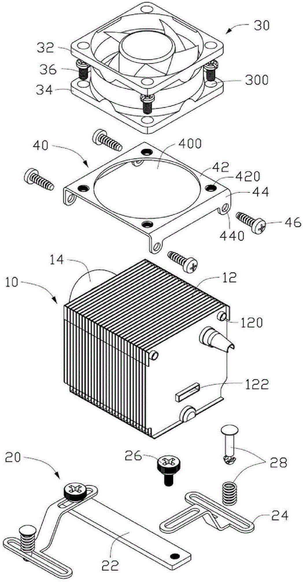
图2是图1的立体分解图。FIG. 2 is an exploded perspective view of FIG. 1 .
图3是图2中散热装置中散热器和扣具的立体分解图。FIG. 3 is a three-dimensional exploded view of the radiator and the buckle in the heat dissipation device in FIG. 2 .
具体实施方式 Detailed ways
请参照图1,本发明一实施例中的散热装置用于对电路板(图未示)上的芯片(图未示)进行散热,该散热装置包括一与芯片接触的散热器10、一安装在散热器10上而将散热装置固定在电路板上的扣具20、一风扇30及一将风扇30固定在散热器10上的固定架40。Please refer to Fig. 1, the heat dissipation device in one embodiment of the present invention is used for dissipating heat to the chip (not shown) on the circuit board (figure not shown), and this heat dissipation device comprises a
请参照图2,所述散热器10由导热性良好的金属材料制成,其整体结构大致呈立方体形,其包括若干鳍片12及一穿设鳍片12的热管14。所述鳍片12具有相同尺寸并相互平行。所述热管14被弯成U形,其具有一吸热部及一放热部(未标号),其吸热部嵌入鳍片12底部的中间位置并与鳍片12垂直,且该吸热部的底面与鳍片12的底面齐平,从而将芯片产生的热量传递至鳍片12上,其放热部垂直穿过鳍片12且靠近鳍片12顶端。该散热器10在其二相对的最外侧鳍片12顶部各向外凸设一凸柱(未标号),每一凸柱内开设一用于安装固定架40的螺孔120。所述鳍片12于靠近其底部位置处开设有一矩形槽道122,该槽道122垂直鳍片12贯通散热器10相对两侧且位于热管14吸热部的正上方位置,用以插设扣具20的相应组件。Referring to FIG. 2 , the
请参照图2及图3,所述扣具20用于将散热装置安装在电路板上,其包括一矩形条状支撑板22、分别位于支撑板22两端的二安装片24、二用于将安装片24固定于支撑板22两端的螺钉26及分别插设于二安装片24一端并与安装片24配合的二扣件28。该支撑板22可沿散热器20的矩形槽道122进入且贯通散热器20,仅保留支撑板22两端在散热器20相对两侧,支撑板22的两端各开设一螺孔220,用以与穿设于安装片24一端的螺钉26配合。每一安装片24由一金属片一体形成,其包括第一安装部242、垂直于第一安装部242的一第二安装部244和从第一安装部242一端倾斜向下延伸并连接第二安装部244一侧的一连接部246。所述二安装片24的二第一安装部242分别通过螺钉26平行地固接在支撑板22两端,每一第一安装部242的中央形成一长椭圆形纵向滑孔2420,用以供螺钉26穿过与支撑板22两端的螺孔220配合而将安装片24连接到支撑板22上,且在螺钉26未处于最紧螺合状态时,安装片24可沿纵向滑孔2420在平行鳍片12的方向来回移动。所述第二安装部244通过扣件28结合至电路板上,其具有长椭圆环状结构且靠近椭圆圆弧端的边缘与连接部246相连接,其中央形成一长椭圆形横向滑孔2440,用以供扣件28穿设。第一安装部242与第二安装部244沿长度方向相互垂直。所述扣件28穿设于安装片24第二安装部244用于将散热装置固定在电路板上,每一扣件28包括一扣件本体(图未标)及套置在该扣件本体上的一弹簧288。所述扣件本体由塑胶材料一体形成,其包括一扣帽282、一自扣帽282中央向下延伸形成的一杆部284及于杆部284末端形成的一倒刺状的卡块286,其中扣帽282的直径大于弹簧288的直径,弹簧288的直径大于第二安装部244的长椭圆形横向滑孔2440宽度,以使弹簧288两端分别抵靠在扣帽282和第二安装部244表面,防止其脱离扣件本体。所述卡块286下压变形后穿过第二安装部244的横向滑孔2440并卡置在第二安装部244下面,弹簧288套设在杆部284上并夹置在扣帽282与第二安装部244之间,该扣件28可沿横向滑孔2440在垂直鳍片12的方向上来回移动。所述螺钉26包括一螺帽262、自螺帽262中央向下延伸形成的一圆形台阶部264和自该台阶部264中央向下延伸形成的一螺杆266。螺帽262顶面形成一十字形沟槽260,用以供一螺丝刀(图未示)进入旋拧该螺钉26。螺杆266表面具有螺纹(图未标)用以与支撑板22上的螺孔220匹配。螺杆266的直径小于第一安装部242的长椭圆形纵向滑孔2420的宽度,台阶部264的直径大于第一安装部242的长椭圆形纵向滑孔2420的宽度,使螺钉26的螺杆266穿过第一安装部242的长椭圆形纵向滑孔2420而使台阶部264抵靠住第一安装部242表面。Please refer to Fig. 2 and Fig. 3, described
所述风扇30为轴流风扇,其结合至固定架40的上表面。该风扇30具有分别自其顶端和底端延伸而出的上凸缘32、下凸缘34及用以固定风扇30的若干螺钉36。上凸缘32和下凸缘34相互平行,于下凸缘34的四角处开设四通孔300,用以供螺钉36穿设。The
所述固定架40用于将风扇30固定在散热器10上,其包括一本体部42、自本体部42相对两侧垂直向下延伸形成的二安装板44。该本体部42中央开设一圆形入风口400,用以供风扇30产生的气流通过。该本体部42四角处开设四环绕入风口400的螺孔420,用以与穿过风扇30通孔300的螺钉36相配合。该二安装板44两端各开设一通孔440,用以供螺钉46穿过与散热器10上的螺孔120配合而将固定架40固定到散热器10上。The
组装该散热装置时,所述风扇30通过四螺钉36穿过其下凸缘34的通孔300与固定架40本体部42的螺孔420配合,而将风扇30锁固在固定架40上;固定架40通过四螺钉46穿过其安装板44的通孔440与散热器10顶部的螺孔120,而将载有风扇30的固定架40锁固在散热器10上;将扣具20的支撑板22插设在散热器20的矩形槽道122内,仅保留支撑板22两端在散热器20二相对外侧;将二螺钉26的螺杆266沿第一安装部242的纵向滑孔2420插入第一安装部242,继而借助一螺丝刀旋拧螺钉26,使螺杆266沿支撑板22的螺孔220进入而与支撑板22螺接,在固紧第一安装部242前,第一安装部242可沿纵向滑孔2420相对螺钉26左右滑动来调节安装片24在支撑板22上的位置,使第二安装部244的横向滑孔2440正对对应的电路板固定孔(图未示)上,再继续旋拧螺钉26使螺钉26的台阶部264顶靠在第一安装部242表面,而将第一安装部242锁紧固定;将扣件28沿第二安装部244的横向滑孔2440插入第二安装部244,并沿第二安装部244左右滑动扣件28而使扣件28的卡块286与电路板的固定孔对齐,向下按压扣件28的扣帽282使弹簧288被压缩而两端分别抵靠在扣帽282和第二安装部244表面,同时卡块286穿过电路板固定孔,直至卡块286卡置在电路板下面的背板上,从而将散热装置牢固地固定在电路板上。When assembling the heat sink, the
与现有技术相比,上述散热装置的扣具可以根据电路板上电子元件周围的固定孔位置对扣具进行调节,使散热装置适于安装在不同规格的电路板上。Compared with the prior art, the fasteners of the heat dissipation device can be adjusted according to the positions of the fixing holes around the electronic components on the circuit board, so that the heat dissipation device is suitable for installation on circuit boards of different specifications.
Claims (13)
Priority Applications (2)
| Application Number | Priority Date | Filing Date | Title |
|---|---|---|---|
| CN200810302094A CN101605446B (en) | 2008-06-11 | 2008-06-11 | Radiating device |
| US12/261,047 US20090308573A1 (en) | 2008-06-11 | 2008-10-30 | Heat dissipation device |
Applications Claiming Priority (1)
| Application Number | Priority Date | Filing Date | Title |
|---|---|---|---|
| CN200810302094A CN101605446B (en) | 2008-06-11 | 2008-06-11 | Radiating device |
Publications (2)
| Publication Number | Publication Date |
|---|---|
| CN101605446A CN101605446A (en) | 2009-12-16 |
| CN101605446B true CN101605446B (en) | 2012-09-05 |
Family
ID=41413698
Family Applications (1)
| Application Number | Title | Priority Date | Filing Date |
|---|---|---|---|
| CN200810302094A Expired - Fee Related CN101605446B (en) | 2008-06-11 | 2008-06-11 | Radiating device |
Country Status (2)
| Country | Link |
|---|---|
| US (1) | US20090308573A1 (en) |
| CN (1) | CN101605446B (en) |
Families Citing this family (13)
| Publication number | Priority date | Publication date | Assignee | Title |
|---|---|---|---|---|
| US8120919B2 (en) * | 2009-12-23 | 2012-02-21 | Coolit Systems Inc. | Adjustable mounting bracket for a computer component |
| TWM390036U (en) * | 2009-12-31 | 2010-10-01 | Shi-Ming Chen | Tightening structure of head dissipation module |
| CN102655730A (en) * | 2011-03-04 | 2012-09-05 | 鸿富锦精密工业(深圳)有限公司 | Heat dissipation device |
| CN103179840A (en) * | 2011-12-26 | 2013-06-26 | 鸿富锦精密工业(深圳)有限公司 | heat sink |
| CN103517613A (en) * | 2012-06-25 | 2014-01-15 | 富瑞精密组件(昆山)有限公司 | Heat radiation device |
| CN103671262A (en) * | 2012-09-14 | 2014-03-26 | 英业达科技有限公司 | Fan structure and shell structure |
| CN103857263B (en) * | 2012-12-07 | 2017-05-10 | 富瑞精密组件(昆山)有限公司 | Cooling device |
| US10070755B2 (en) | 2014-12-18 | 2018-09-11 | Weber-Stephen Products Llc | Fuel efficient grill for direct and indirect cooking |
| US9414481B1 (en) * | 2015-04-02 | 2016-08-09 | Cooler Master Technology Inc. | Heat sink fastener |
| CN109302827A (en) * | 2017-07-25 | 2019-02-01 | 鸿富锦精密工业(武汉)有限公司 | Heat dissipation module and electronic device using the same |
| TWI776504B (en) * | 2021-05-12 | 2022-09-01 | 訊凱國際股份有限公司 | Fixed structure of heat sink |
| TWI772243B (en) * | 2022-01-12 | 2022-07-21 | 尼克森微電子股份有限公司 | Power module and a power device |
| FR3147663B1 (en) * | 2023-04-07 | 2025-04-18 | St Microelectronics Int Nv | FIXED HEAT SINK ON THE SUBSTRATE OF AN INTEGRATED CIRCUIT PACKAGE |
Citations (3)
| Publication number | Priority date | Publication date | Assignee | Title |
|---|---|---|---|---|
| US6246584B1 (en) * | 1999-04-16 | 2001-06-12 | Hon Hai Precision Ind. Co., Ltd. | Heat sink |
| US20050036289A1 (en) * | 2003-08-13 | 2005-02-17 | Lee Hsieh Kun | Heat dissipation device |
| US20070211437A1 (en) * | 2006-03-07 | 2007-09-13 | Chih-Peng Liao | Fixing Means For Heat Dissipator |
Family Cites Families (9)
| Publication number | Priority date | Publication date | Assignee | Title |
|---|---|---|---|---|
| US2920853A (en) * | 1957-11-18 | 1960-01-12 | Bufogle John | Guide for the ball float of flush tanks |
| US4141524A (en) * | 1977-02-28 | 1979-02-27 | Corvese Jr Louis | Tube holder for immobile patients |
| KR100457220B1 (en) * | 2002-02-27 | 2004-11-16 | 잘만테크 주식회사 | Heat sink device for cooling chipset |
| CN2757509Y (en) * | 2004-12-04 | 2006-02-08 | 鸿富锦精密工业(深圳)有限公司 | Radiator locking device |
| US7694363B2 (en) * | 2005-02-15 | 2010-04-13 | Finger Lakes Intellectual Property, Llc | Foundation headboard bracket system for bed |
| TWM278206U (en) * | 2005-05-11 | 2005-10-11 | Cooler Master Co Ltd | Cooling and fixing device |
| US7239518B2 (en) * | 2005-11-01 | 2007-07-03 | Fu Zhun Precision Industry (Shen Zhen) Co., Ltd. | Universal locking device for heat sink |
| US7609522B2 (en) * | 2006-12-01 | 2009-10-27 | Fu Zhun Precision Industry (Shen Zhen) Co., Ltd. | Heat sink assembly |
| CN101242732B (en) * | 2007-02-08 | 2011-01-05 | 鸿富锦精密工业(深圳)有限公司 | Heat sink combination |
-
2008
- 2008-06-11 CN CN200810302094A patent/CN101605446B/en not_active Expired - Fee Related
- 2008-10-30 US US12/261,047 patent/US20090308573A1/en not_active Abandoned
Patent Citations (3)
| Publication number | Priority date | Publication date | Assignee | Title |
|---|---|---|---|---|
| US6246584B1 (en) * | 1999-04-16 | 2001-06-12 | Hon Hai Precision Ind. Co., Ltd. | Heat sink |
| US20050036289A1 (en) * | 2003-08-13 | 2005-02-17 | Lee Hsieh Kun | Heat dissipation device |
| US20070211437A1 (en) * | 2006-03-07 | 2007-09-13 | Chih-Peng Liao | Fixing Means For Heat Dissipator |
Also Published As
| Publication number | Publication date |
|---|---|
| CN101605446A (en) | 2009-12-16 |
| US20090308573A1 (en) | 2009-12-17 |
Similar Documents
| Publication | Publication Date | Title |
|---|---|---|
| CN101605446A (en) | Heat abstractor | |
| CN101848623B (en) | Heat abstractor | |
| US7891411B2 (en) | Heat dissipation device having a fan for dissipating heat generated by at least two electronic components | |
| CN101835364B (en) | Heat-dissipating device | |
| CN101896053B (en) | Cooling module | |
| CN101466241A (en) | Radiating device | |
| CN102111985A (en) | Heat-dissipating device | |
| US8422226B2 (en) | Heat dissipation device | |
| CN102056456A (en) | Heat dissipating device | |
| CN101778553A (en) | Radiator | |
| CN102111984A (en) | Heat dissipation device | |
| CN101662919B (en) | Radiating device | |
| US20040109301A1 (en) | Cooling device for an integrated circuit | |
| US20120222835A1 (en) | Heat dissipating device | |
| US20090120613A1 (en) | Heat sink | |
| CN102843894B (en) | Heat abstractor and fan Fixture thereof | |
| CN100534283C (en) | Combination of cooling device | |
| US7428153B2 (en) | Heat dissipation assembly | |
| CN101742885B (en) | Radiator fixing device | |
| US7965507B2 (en) | Heat dissipation device having a fan holder thereon | |
| CN100562237C (en) | heat sink | |
| US20080316705A1 (en) | Heat dissipation device having a fan mounted thereon | |
| CN102117783A (en) | Heat-radiating device | |
| CN216982405U (en) | Heat sink and its fixing components | |
| CN101466242A (en) | Radiating device |
Legal Events
| Date | Code | Title | Description |
|---|---|---|---|
| C06 | Publication | ||
| PB01 | Publication | ||
| EE01 | Entry into force of recordation of patent licensing contract |
Assignee: Hongfutai precision electronics (Yantai) Co., Ltd. Assignor: Hung Fujin Precision Industry (Shenzhen) Co., Ltd.|Hon Hai Precision Industry Co Contract record no.: 2010990000395 Denomination of invention: Heat sink combination License type: Exclusive License Open date: 20091216 Record date: 20100629 |
|
| C10 | Entry into substantive examination | ||
| SE01 | Entry into force of request for substantive examination | ||
| C14 | Grant of patent or utility model | ||
| GR01 | Patent grant | ||
| CF01 | Termination of patent right due to non-payment of annual fee |
Granted publication date: 20120905 Termination date: 20140611 |
|
| EXPY | Termination of patent right or utility model |