CN101553843A - Interacting with 2D content on 3D surfaces - Google Patents
Interacting with 2D content on 3D surfaces Download PDFInfo
- Publication number
- CN101553843A CN101553843A CNA2007800437399A CN200780043739A CN101553843A CN 101553843 A CN101553843 A CN 101553843A CN A2007800437399 A CNA2007800437399 A CN A2007800437399A CN 200780043739 A CN200780043739 A CN 200780043739A CN 101553843 A CN101553843 A CN 101553843A
- Authority
- CN
- China
- Prior art keywords
- input equipment
- content
- point
- scene
- seizure
- Prior art date
- Legal status (The legal status is an assumption and is not a legal conclusion. Google has not performed a legal analysis and makes no representation as to the accuracy of the status listed.)
- Pending
Links
Images


Classifications
-
- G—PHYSICS
- G06—COMPUTING; CALCULATING OR COUNTING
- G06F—ELECTRIC DIGITAL DATA PROCESSING
- G06F3/00—Input arrangements for transferring data to be processed into a form capable of being handled by the computer; Output arrangements for transferring data from processing unit to output unit, e.g. interface arrangements
- G06F3/01—Input arrangements or combined input and output arrangements for interaction between user and computer
- G06F3/048—Interaction techniques based on graphical user interfaces [GUI]
- G06F3/0481—Interaction techniques based on graphical user interfaces [GUI] based on specific properties of the displayed interaction object or a metaphor-based environment, e.g. interaction with desktop elements like windows or icons, or assisted by a cursor's changing behaviour or appearance
- G06F3/04815—Interaction with a metaphor-based environment or interaction object displayed as three-dimensional, e.g. changing the user viewpoint with respect to the environment or object
-
- G—PHYSICS
- G06—COMPUTING; CALCULATING OR COUNTING
- G06F—ELECTRIC DIGITAL DATA PROCESSING
- G06F3/00—Input arrangements for transferring data to be processed into a form capable of being handled by the computer; Output arrangements for transferring data from processing unit to output unit, e.g. interface arrangements
- G06F3/01—Input arrangements or combined input and output arrangements for interaction between user and computer
- G06F3/03—Arrangements for converting the position or the displacement of a member into a coded form
- G06F3/033—Pointing devices displaced or positioned by the user, e.g. mice, trackballs, pens or joysticks; Accessories therefor
- G06F3/0346—Pointing devices displaced or positioned by the user, e.g. mice, trackballs, pens or joysticks; Accessories therefor with detection of the device orientation or free movement in a 3D space, e.g. 3D mice, 6-DOF [six degrees of freedom] pointers using gyroscopes, accelerometers or tilt-sensors
-
- G—PHYSICS
- G06—COMPUTING; CALCULATING OR COUNTING
- G06F—ELECTRIC DIGITAL DATA PROCESSING
- G06F3/00—Input arrangements for transferring data to be processed into a form capable of being handled by the computer; Output arrangements for transferring data from processing unit to output unit, e.g. interface arrangements
- G06F3/01—Input arrangements or combined input and output arrangements for interaction between user and computer
- G06F3/03—Arrangements for converting the position or the displacement of a member into a coded form
- G06F3/033—Pointing devices displaced or positioned by the user, e.g. mice, trackballs, pens or joysticks; Accessories therefor
- G06F3/038—Control and interface arrangements therefor, e.g. drivers or device-embedded control circuitry
-
- G—PHYSICS
- G06—COMPUTING; CALCULATING OR COUNTING
- G06F—ELECTRIC DIGITAL DATA PROCESSING
- G06F3/00—Input arrangements for transferring data to be processed into a form capable of being handled by the computer; Output arrangements for transferring data from processing unit to output unit, e.g. interface arrangements
- G06F3/01—Input arrangements or combined input and output arrangements for interaction between user and computer
- G06F3/048—Interaction techniques based on graphical user interfaces [GUI]
- G06F3/0484—Interaction techniques based on graphical user interfaces [GUI] for the control of specific functions or operations, e.g. selecting or manipulating an object, an image or a displayed text element, setting a parameter value or selecting a range
- G06F3/04842—Selection of displayed objects or displayed text elements
Abstract
Various technologies and techniques are disclosed that enable interaction with 2D content placed on a 3D surface. The system determines where relative to a 3D surface an input device is located. If the input device is hitting a 3D surface, a hidden content in 2D is positioned so that a point representing the area hit on the 3D surface lines up with a corresponding point on the hidden content in 2D. For example, when a request is received for the input device position when an input device is detected at a location in a scene, the 3D surface is projected into two dimensions. A closest point is calculated on the projected. 3D surface to a 2D location of the input device. The closest point is provided in response to be used in positioning the hidden content with the corresponding point of the 3D surface.
Description
Background
In 2 dimension (2D) environment, system can know by determining movable X and Y coordinates simply the user has selected what zone or otherwise mutual with what zone.Yet, in 3 dimension (3D) worlds, seek always not flat-footed with respect to the X/Y coordinate of the lip-deep interactive 2D element of 3D.For example, can be placed in such as on the 3D surfaces such as sphere such as 2D objects such as user interfaces.Be placed under the situation on 3D surface at this 2D object, may be difficult to process user and this and be projected in the mutual of 2D object among the 3D now.
General introduction
Disclose and enabled and place the lip-deep 2D content of 3D to carry out mutual various technology and method.System determines that input equipment with respect to the 3D surface alignment wherein.If the hiding content among the 2D is then located so that the corresponding point on the hiding content among the point that is illustrated in the zone of clashing on the 3D surface and the 2D comes into line in input equipment bump 3D surface.In one implementation, when the position in scene detected not input equipment above the border of interactive 2D content, when the request that receives this input equipment position, the 3D surface was projected in 2 dimensions.On the 3D surface of institute's projection, calculate point near the 2D position of input equipment.In response to being used to locate hiding content, provide the point of the correspondence on 3D surface to this immediate point.
In one implementation, depend on whether specific 3D surface has the different process of following of catching.For example, if the 3D surface in the 3D scene does not have seizure, and if input equipment bump 3D surface, then using texture coordinate to determine to have clashed into what point on the hiding content in 2D on the 3D triangle.Hiding content is moved to a position subsequently, so that hiding content and the lip-deep corresponding point of 3D come into line.Similarly, if the 3D surface in the 3D scene has seizure, and if determine that input equipment with this seizure content bump 3D surface, then uses texture coordinate and previous described process to come into line hiding content.
In another is realized, if the 3D surface in the 3D scene has seizure, if and determine that input equipment is with catching content bump 3D surface, then system-computed is caught the border of content, seek on the border point, and this immediate point on the border is placed the below of the position of input equipment near the position of input equipment.
Provide this general introduction so that introduce some notions that will further describe in the following detailed description in simplified form.This general introduction is not intended to identify the key feature or the essential feature of theme required for protection, is not intended to be used to help to determine the scope of theme required for protection yet.
The accompanying drawing summary
Fig. 1 is the diagram of the computer system of a realization.
Fig. 2 is the diagram of the interactive 3D application program of a realization operating on the computer system of Fig. 1.
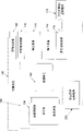
Fig. 3 is the high level process flow diagram of a realization of the system of Fig. 1.
Fig. 4 is the processing flow chart of a realization of the system of Fig. 1, related each stage when it is illustrated in and provides the input equipment position with the 3D object.
Fig. 5 is the processing flow chart of a realization of the system of Fig. 1, and it is illustrated in enables and related more detailed stage when placing the lip-deep 2D content of 3D mutual.
Fig. 6 is the analog image of a realization of the system of Fig. 1, and it is illustrated in the 2D that hides content when not catching and represents.
Fig. 7 is the analog image of a realization of the system of Fig. 1, and it is illustrated in when not catching and the 3D surface of hiding content exchange.
Fig. 8 is the analog image of a realization of the system of Fig. 1, and it is illustrated in and covers the lip-deep 2D of 3D when not catching and represent.
Fig. 9 is the analog image of a realization of the system of Fig. 1, and it is illustrated in the 3D surface that has the Show Button and text when catching.
Figure 10 is the analog image of a realization of the system of Fig. 1, and it is illustrated in and has the 3D surface shown in Figure 9 of selecting the part of text when catching.
Figure 11 is the analog image of a realization of the system of Fig. 1, and it illustrates the relevant immediate edge point of 2D of wherein expecting on the orientation on input equipment and 3D surface shown in Figure 10.
Figure 12 is the analog image of a realization of the system of Fig. 1, and it illustrates the 2D text box with seizure.
Figure 13 is the analog image of a realization of the system of Fig. 1, and it illustrates the limit of the image that obtains Figure 12 and the profile that 2D comes to provide on 3D with the 2D form 2D content is returned in these limit projections.
Describe in detail
Be to promote understanding to principle of the present invention, now in addition reference of each embodiment shown in the figure, simultaneously also will with concrete language description they.But, it will be appreciated that, and do the restriction on the scope thus unintentionally.Any change in described embodiment and further change, and the further application of principle described herein can expect it will will be that those skilled in the art are thinkable usually.
This system can be described as providing and placing the mutual application program of the lip-deep 2D content of 3D in general context, but this system also is used for other purpose in addition.In one implementation, one or more technology described herein can be implemented as figure and present feature in the program, such as be included in such as
 Deng the program of any other type that presents in the operating system environment or from processing graphics or those features in the service.In another was realized, one or more technology described herein are implemented as handled the feature that allows other application program that the 2D content uses with the 3D surface.
In one implementation, system provides mutual with the 3D surface by using hiding 2D content.Real interactive 2D content keeps hiding, but does not hide the outward appearance of this 2D content of hiding and be placed on the 3D.Should hide content locatees with the mode that the outward appearance of the content that is presented on the 3D surface is carried out mutual trial with the intercepting user.That term as used herein " hide content " is intended to comprise is invisible because of it, being decided to be can not descried size, be positioned at after another object etc. thereby the unwitnessed 2D content of user.In another was realized, in the position of any part request input equipment of 2D content or request when catching, the 3D of this 2D content represented to be projected back 2D.The border of the content of this projection is used to determine any input request that how to respond from the 3D surface of being caught subsequently.Term as used herein " seizure " means when 2D content requests notice input equipment state changes.
As shown in Figure 1, the exemplary computer system that is used to realize one or more parts of this system comprises such as computing equipment 100 computing equipments such as grade.In its most basic configuration, computing equipment 100 generally includes at least one processing unit 102 and storer 104.The definite configuration and the type that depend on computing equipment, storer 104 can be (as the RAM) of volatibility, non-volatile (as ROM, flash memory etc.) or both certain combinations.This most basic configuration is come illustration by dotted line 106 in Fig. 1.
In addition, equipment 100 also can have additional feature/function.For example, equipment 100 also can comprise extra storage (removable and/or not removable), comprising but be not limited to disk, CD or tape.Such extra storage in Fig. 1 by removable storage 108 with can not mobile storage 110 illustrate.Computer-readable storage medium comprises to be used to store such as any method of information such as computer-readable instruction, data structure, program module or other data or volatibility that technology realizes and non-volatile, removable and removable medium not.Storer 104, removable storage 108 and can not mobile storage 110 all be the example of computer-readable storage medium.Computer-readable storage medium includes but not limited to, RAM, ROM, EEPROM, flash memory or other memory technology, CD-ROM, digital versatile disc (DVD) or other optical storage, tape cassete, tape, disk storage or other magnetic storage apparatus or can be used for storing information needed and can be by any other medium of equipment 100 visits.Any such computer-readable storage medium can be the part of equipment 100.
Continuation now forwards Fig. 2 to reference to Fig. 1, and it shows the interactive 3D application program 200 that runs on the computing equipment 100.Interactive 3D application program 200 is to reside in one of application program on the computing equipment 100.Yet, be appreciated that interactive 3D application program 200 can be alternatively or additionally be embodied on one or more computing machines computer executable instructions and/or with different modification shown in Figure 1.Alternatively or additionally, one or more parts of interactive 3D application program 200 can be the part of system storage 104, can be on other computing machine and/or application program 115, maybe can be thinkable other this type of modification of technician of computer software fields.
Interactive 3D application program 200 comprises the programmed logic 204 of being responsible for carrying out some or all technology described here.Programmed logic 204 comprises the logic 206 that is used for determining to exist the demand (for example, determining) of upgrading hiding content when receiving request or on program; Be used for determining that input equipment (for example mouse, stylus etc.) is positioned at logic where 208 with respect to the 3D surface; Be used for determining whether input equipment clashes into (hit) logic 210 on 3D surface; Being used for determining in system that input equipment does not clash into will hide content under the situation on 3D surface and (for example become inertia, to hide content and remove or otherwise remove or make its inertia, so that the user can be unexpectedly not mutual with it from input equipment) logic 212; Be used for determining that in system input equipment has clashed into location 2D object under the situation on 3D surface really, so that 3D is lip-deep with point that input equipment clashed into and the logic 214 that should hiding 2D object comes into line (for example mobile so that identical point comes into line); Be used to wait for another logic 216 of indicating and correspondingly responding of the demand (for example reception is asked or determined) that exists renewal to hide content on program; And other logic 220 that is used to operate this application program.In one implementation, programmed logic 204 can be used for by programming, as using to single the calling of a process in the programmed logic 204 and from another routine call.
Turn to Fig. 3-5 now, and continue, described each stage of the one or more realizations that are used to realize interactive 3D application program 200 in more detail with reference to Fig. 1-2.Fig. 3 is the high level process flow diagram of interactive 3D application program 200.In one form, the process of Fig. 3 realizes in the operation logic of computing equipment 100 at least in part.This process begins at starting point 240 places, can randomly determine to exist the demand (for example, determining when receiving request or on program) (stage 242) of hiding content of upgrading.System determines that input equipment (for example mouse, stylus etc.) is with respect to 3D surface alignment (stage 244) wherein.If input equipment does not clash into (for example contact) 3D surface (for example general area in the 3d space) (decision-point 246), then will hide content and (for example become inertia, remove or otherwise remove or make its inertia from input equipment, so that the user can be unexpectedly not mutual with it) (stage 248).If input equipment has clashed into 3D surface (decision-point 246) really, then locate the 2D object, come into line (for example move so that identical point come into line) (stage 250) with the point that input equipment clashed into the 2D object that should hide so that 3D is lip-deep.System can randomly wait for and exist another indication of upgrading the demand of hiding content also correspondingly to respond (stage 252).This process finishes at end point 256 places.
Fig. 4 is illustrated in a realization in each related when the position of input equipment with respect to the 3D surface is provided stage.In one form, the process of Fig. 4 realizes in the operation logic of computing equipment 100 at least in part.This process begins at starting point 270 places, when detecting input equipment in the somewhere of scene, receives (for example from such as zones such as any 3D geometry, balls) request or inquiry (stage 272) to the input equipment position.Obtain this 3D surface and it is projected in 2 dimensions (stage 274).Calculate the point (stage 276) that approaches the 2D position of input equipment in this projection most.Immediate point is in response to request or inquires about the position of being returned (for example turning back to the request object in the 3d space) (stage 278) on the projection objects.This process finishes at end point 280 places.
Fig. 5 is illustrated in and enables and the realization in related more detailed stage when placing the lip-deep 2D content of 3D mutual.In one form, the process of Fig. 5 realizes in the operation logic of computing equipment 100 at least in part.This process begins at starting point 310 places, can randomly determine to exist the demand (" carrying out (on) " incident etc.) (stage 312) of hiding content of upgrading.If system determines the 3D surface and do not have seizure (decision-point 314), then carry out impact test 3D scene and determine that where input equipment is positioned at (stage 316) with respect to the 3D surface.If the 3D surface by bump (decision-point 320), then will not hide content and remove (stage 324) from input equipment.If the 3D surface by bump (decision-point 320), is then using texture coordinate to seek what point (stage 326) that has clashed on the 2D content on the 3D triangle.The 2D content is placed in to be hidden in the layer, and moves and should hide layer so that each point comes into line (stage 326).
If system determines the 3D surface and have seizure (decision-point 314) really, then carry out impact test 3D scene and determine that where input equipment is positioned at (stage 318) with respect to the 3D surface.System determines whether the 3D surface is clashed into (decision-point 322) by (for example by input equipment) with catching content.If then using texture coordinate to seek what point (stage 326) that has clashed on the 2D content on the 3D triangle.The 2D content is placed in to be hidden in the layer, and moves and should hide layer so that each point comes into line (stage 326).Do not clashed into (decision-point 322) if system determines the 3D surface, then calculated the border (stage 328) of the content of being caught with catching content.Approach most the point of input equipment position on the border, location, and this immediate point on the border is placed below, input equipment position (stage 328).This process finishes at end point 330 places.
Now turn to Fig. 6-13, use analog image to illustrate in greater detail each stage of Fig. 3-5.In Fig. 6-8, use some exemplary simulated images that the 3D surface is shown and do not have some possible scenes when catching.The description that these analog images and they are followed provides the further diagram of Fig. 5's and/or some other technology described herein stage 314,316,320,324 and 326.Fig. 6 is the analog image 400 of a realization of the system of Fig. 1, and it illustrates the 2D that hides content when not catching and represents.Analog image 500 comprises the content that is mapped to spheroid.Fig. 7 comprises the analog image 500 that the image 400 that Fig. 6 is shown is mapped to spheroid (for example 3D).Fig. 8 comprises analog image 600, and it illustrates how to align hides content so that the slider bar part that 3D is lip-deep, input equipment is arranged in its top is identical with the slider bar of 2D.Pointing-input device will be subsequently and the thumb widget interaction.Because kept this mapping, thus the 3D surface correctly notified input equipment when to enter and left them, with and be positioned at what part of they self top.This establishment can be carried out mutual result with the 2D content on the 3D.In one implementation, input equipment moves as hiding the signal that content need upgrade and follows the tracks of.
Now will use some non-limiting examples to describe and how the 2D content map be reached the result shown in Fig. 6-8 to the 3D surface.At input equipment during not in the 3D surface, hide then that layer can be placed in any position so that input equipment not above it.In one implementation, required behavior is that the lip-deep 2D content of 3D is not taken action, and as input equipment above it, and any other incident should not influence it.To hide layer makes it not be apprised of mobile or click etc. away from the input equipment placement.
For the purpose of example, suppose that all 3D surfaces all are made up of triangle, and all triangles all has the texture coordinate that is associated with it.Which part of texture coordinate specify image (texture) should be displayed on the triangle.For example, suppose that texture coordinate is in (0,0) in the scope of (1,1), wherein (0,0) is the upper left corner of image, and (1,1) is the lower right corner of image.If then texture coordinate is (0,0), (1,0) and (0,1), then the upper left of image partly is displayed on the triangle.In addition, suppose that being presented at the lip-deep 2D content of 3D can be represented as image, and this image is the texture that is applied to the 3D surface of this image.For example, Fig. 6 can be considered to texture, and texture coordinate is to make its coordinate around spheroid, as shown in Figure 7.
Now, at input equipment during in the 3D surface, light be shot in to the 3 d scene to see itself and this 3D surface what partly intersect.This can finish with many standard techniques.In case it is what that system knows crossing, then can determine on the triangle the point that is clashed into and texture coordinate.In case determined texture coordinate, owing to also know texture, then system can be mapped to position on the 2D content from this texture coordinate.This position is the accurate point of 3D surface.Be correct location, system moves hiding content so that formerly in the part position of being calculated directly below the input equipment position.Directly below the same position on the hiding content, its both is directly below input equipment for the point of 3D surface.Therefore, if the user clicks or otherwise from this position input, then they will click/import on the hiding content with 3D on the 2D content on accurate identical point.Equally, when input equipment moves, because this location, hide content and its input equipment above the 2D on the 3D represents will to be apprised of accurate identical point and move.
Now turn to Fig. 9-13, show some exemplary simulated images and illustrate that wherein the 3D surface has some possible scenes of seizure.The description that these analog images and they are followed provides the further diagram of Fig. 5's and/or some other technology described herein stage 314,318,322,326 and 328.In one implementation, when the 2D element on 3D obtained catching, correct hiding content location may become more complicated.As an example, in 3D, because the projection of 3D to the 2D plane, the position of input equipment is in fact corresponding to a line in the 3d space.In addition, the 3D surface with seizure also can be mapped to any any geometry.Therefore, when input equipment was positioned at the 3D surface, where impact test indication input equipment was positioned at respect to the 2D visual element.When it leaves the 3D surface, because above problem no longer includes the direct answer to this problem: the 2D point can be on any geometry corresponding to 3D line and 2D content.Equally, because the 3D surface has seizure, so it wants to receive all incidents.Before, when not relating to seizure, system only need guarantee that input equipment is always above correct object.Now, have seizure, then system need locate and hide content so that it is in the suitable position with respect to the object with seizure.Analog image shown in Fig. 9-11 illustrates in greater detail this point.
In one implementation, be that this 3D problem is reverted back 2D to one of this problem possible solution.Under normal 2D situation, the conversion that is applied to this content can be used to the input equipment position is converted to the local coordinate system of this content.This position through conversion makes this content know where input equipment is in respect to it subsequently.In 3D, because the multiple orientation of geometry and texture coordinate layouts, be difficult to sometimes to judge that relative coordinate system that the 3D point is arranged in the 2D content on the 3D where.In one implementation, for approximate this point, after the 2D content on the 3D is being projected to screen space, calculates its profile and locate input equipment based on this projection subsequently.Fig. 9-11 illustrates in greater detail this point.
The analog image 700 of Fig. 9 illustrates the 2D content on the 3D.Analog image 750 on Figure 10 illustrates has selected text, and input equipment is moved to the point that leaves this object.Figure 11 illustrates the have text box analog image 800 of profile of (object that promptly has seizure).This profile is used to locate hiding content subsequently.
After profile can be used, calculate on this profile point near the input equipment position, and the point that is considered to be " hit " with this point on the rear profile, and it is placed in the below of input equipment position.In the example shown, carry out " T " of highlight up to the central authorities of image 750.Because input equipment places by immediate edge point, thus trend towards alternately in 2D, taking action as it because hiding content be based on input equipment the most approaching with 3D on the 2D content on the position locate.Be placed on immediate edge point place by hiding content, system indicates its expection input equipment where to be positioned at respect to the 2D on the orientation on 3D surface.
Carry out with reference to the described process of figure 9-11 for reality, system-computed has the border of the object of seizure, and it is relevant that this seizure and this object are comprised in interior 2D content.As example, consider the 2D content shown in Figure 12-13.Suppose that text box has seizure.In Figure 12, profile is marked with runic in the border of the text box that comprises in the image 900.These borders can be converted into texture coordinate, because to have the border on the 3D surface of seizure be known and 2D content size as a whole also is known.Use texture coordinate, system can check each triangle of position, 3D surface grid thereon subsequently, and seeks those triangles that comprise the texture coordinate that intersects with boundary coordinate.For example, suppose to have a triangle, and the triangle with texture coordinate is as the same being drawn shown on the 2D content among Figure 12.Systems inspection checks whether intersect with the border on the 3D surface with seizure on this leg-of-mutton limit, and they intersect (they intersect with the text box with seizure) really in this case.If gore is to the viewer, and any and its of boundary edge intersect, and then the limit of boundary edge and triangle intersect is added to final tabulation.With the limit that is added shown in the image 950 of Figure 13.By carrying out these steps, determine the visual limit of intersecting with the border on the 3D surface of being caught.
In one implementation, system also follow the tracks of which gore to the viewer and which dorsad.If two triangles are shared limits, user oriented and one is the user dorsad, and then system can also add the part in the border on the 3D surface of being caught on this shared limit to final tabulation.This may be necessary, so that calculate visual boundary.As the non-limiting example of this situation, consider the spheroid among Fig. 9.The left side and the right all are sihouette limit (that is, the limit not only have visual triangle but also have not visible triangle).System adds these whole visible contours (as shown in figure 11) of calculating the 3D surface of being caught.Otherwise the leftmost side and far right images will be lost, and will not calculate complete profile.In case determined the tabulation on limit, then subsequently 2D returned in their projections.This provides the profile of the 2D content on the 3D with the 2D form.Subsequently, calculate on these limits point near input equipment.This point has its oneself texture coordinate, and this texture coordinate as above is used to locate hiding content.Depend on required behavior, the border on the 3D surface of can overstriking catching is further removed from the 3D surface of being caught if necessary.
Although used to the special-purpose language description of architectural feature and/or method action this theme, be appreciated that subject matter defined in the appended claims is not necessarily limited to above-mentioned concrete feature or action.On the contrary, above-mentioned concrete feature and action are disclosed as the exemplary forms that realizes claim.Interior all equivalents, change and the correction of scope that falls into the spirit of said and/or the described realization of claims all expected to be protected.
For example, the computer software fields those of ordinary skill will appreciate that client computer and/or server layout, user interface screen content and/or the data layout described in the example of this discussion can be on one or more computing machine tissue differently, with comprise than described in the example still less or more option or feature.
Claims (20)
1. one kind has and is used to make computing machine to carry out the computer-readable medium of the computer executable instructions of following steps, and described step comprises:
Determine that input equipment with respect to the 3D surface alignment wherein; And
If described input equipment clashes into described 3D surface, then locate the hiding content among the 2D so that the corresponding point on the described hiding content among the point that is illustrated in the zone of clashing on the described 3D surface and the 2D comes into line.
2. computer-readable medium as claimed in claim 1 is characterized in that, also has to be used to make computing machine to carry out the computer executable instructions of following steps, and described step comprises:
If described input equipment does not clash into described 3D surface, then make described hiding content inertia.
3. computer-readable medium as claimed in claim 1 is characterized in that, also has to be used to make computing machine to carry out the computer executable instructions of following steps, and described step comprises:
Before where definite described input equipment is positioned at respect to described 3D surface, determine to exist the demand of upgrading described hiding content.
4. one kind is used to provide the method for input equipment with respect to the position on 3D surface, said method comprising the steps of:
When the position in scene detects input equipment, receive request to the input equipment position;
In 2 dimensions of 3D surface projection in the described scene;
Calculate on the 3D surface of institute's projection the point of the 2D position of approaching described input equipment; And
Return described immediate point in response to described request.
5. method as claimed in claim 4 is characterized in that described input equipment is a mouse.
6. method as claimed in claim 4 is characterized in that described input equipment is a stylus.
7. method as claimed in claim 4 is characterized in that described request receives from a zone.
8. method as claimed in claim 7 is characterized in that, described zone is any 3D geometry.
9. one kind has and is used to make computing machine to carry out the computer-readable medium of the computer executable instructions of step as claimed in claim 4.
10. mutual method that is used to enable and place the lip-deep 2D content of 3D said method comprising the steps of:
The hiding content of determining to be in the 2D in the 3D scene needs to upgrade;
Determine the position of input equipment in described 3D scene; And
If the 3D surface in the described 3D scene does not have seizure, determine then whether described input equipment clashes into the 3D surface in the described 3D scene, if and described input equipment has clashed into described 3D surface really, then on the 3D triangle, use texture coordinate to determine to have clashed on the hiding content in 2D what point in a plurality of points, and described hiding content is moved on to a position so that described hiding content comes into line with the lip-deep corresponding point of described 3D.
11. method as claimed in claim 10 is characterized in that, also comprises:
If the 3D surface in the described 3D scene has seizure, determine then whether described input equipment clashes into described 3D surface with the seizure content.
12. method as claimed in claim 11 is characterized in that, also comprises:
If the 3D surface in the described 3D scene has seizure, if and determine that described input equipment has clashed into described 3D surface with described seizure content, then on described 3D triangle, use texture coordinate to determine to have clashed on the described hiding content in 2D what point in a plurality of points, and described hiding content is moved on to described position so that described hiding content comes into line with the lip-deep corresponding point of described 3D.
13. method as claimed in claim 11 is characterized in that, also comprises:
If the 3D surface in the described 3D scene has seizure, if and determine that described input equipment does not clash into described 3D surface with described seizure content, then calculate the border of described seizure content, seek on the described border point of the position of approaching described input equipment, and immediate point on the described border is placed the below of the position of described input equipment.
14. method as claimed in claim 10 is characterized in that, from described input equipment just when moving event takes place, determine that described hiding content needs to upgrade.
15. method as claimed in claim 10 is characterized in that, described input equipment is a mouse.
16. method as claimed in claim 10 is characterized in that, described input equipment is a stylus.
17. method as claimed in claim 10 is characterized in that, the demand of upgrading described hiding content be receive from a zone to the request of the position of described input equipment the time determine.
18. method as claimed in claim 17 is characterized in that, described zone is any 3D geometry.
19. method as claimed in claim 10 is characterized in that, also comprises:
If the 3D surface in the described 3D scene does not have seizure, and if determine that described input equipment does not clash into the 3D surface in the described 3D scene, then removes described hiding content from the position of described input equipment.
20. one kind has and is used to make computing machine to carry out the computer-readable medium of the computer executable instructions of step as claimed in claim 10.
Applications Claiming Priority (2)
| Application Number | Priority Date | Filing Date | Title |
|---|---|---|---|
| US11/605,183 | 2006-11-28 | ||
| US11/605,183 US20080122839A1 (en) | 2006-11-28 | 2006-11-28 | Interacting with 2D content on 3D surfaces |
Publications (1)
| Publication Number | Publication Date |
|---|---|
| CN101553843A true CN101553843A (en) | 2009-10-07 |
Family
ID=39463202
Family Applications (1)
| Application Number | Title | Priority Date | Filing Date |
|---|---|---|---|
| CNA2007800437399A Pending CN101553843A (en) | 2006-11-28 | 2007-11-27 | Interacting with 2D content on 3D surfaces |
Country Status (8)
| Country | Link |
|---|---|
| US (1) | US20080122839A1 (en) |
| EP (1) | EP2095326A1 (en) |
| JP (1) | JP2010511228A (en) |
| KR (1) | KR20090084900A (en) |
| CN (1) | CN101553843A (en) |
| MX (1) | MX2009004894A (en) |
| TW (1) | TW200828098A (en) |
| WO (1) | WO2008067330A1 (en) |
Cited By (2)
| Publication number | Priority date | Publication date | Assignee | Title |
|---|---|---|---|---|
| CN102915232A (en) * | 2011-08-01 | 2013-02-06 | 华为技术有限公司 | 3D (three-dimensional) controls interaction method and communication terminal |
| CN109087402A (en) * | 2018-07-26 | 2018-12-25 | 上海莉莉丝科技股份有限公司 | Method, system, equipment and the medium of particular surface form are covered in the particular surface of 3D scene |
Families Citing this family (10)
| Publication number | Priority date | Publication date | Assignee | Title |
|---|---|---|---|---|
| KR101416235B1 (en) * | 2008-02-12 | 2014-07-07 | 삼성전자주식회사 | Method and apparatus for 3D location input |
| US8436816B2 (en) | 2008-10-24 | 2013-05-07 | Apple Inc. | Disappearing button or slider |
| US8854357B2 (en) | 2011-01-27 | 2014-10-07 | Microsoft Corporation | Presenting selectors within three-dimensional graphical environments |
| US9361283B2 (en) | 2011-11-30 | 2016-06-07 | Google Inc. | Method and system for projecting text onto surfaces in geographic imagery |
| US9167999B2 (en) | 2013-03-15 | 2015-10-27 | Restoration Robotics, Inc. | Systems and methods for planning hair transplantation |
| US9320593B2 (en) | 2013-03-15 | 2016-04-26 | Restoration Robotics, Inc. | Systems and methods for planning hair transplantation |
| CN103529943B (en) * | 2013-10-17 | 2016-05-04 | 合肥金诺数码科技股份有限公司 | A kind of human body projection exchange method based on fluid physics simulation system |
| KR20230123931A (en) | 2020-12-20 | 2023-08-24 | 루머스 리미티드 | Image projector with laser scanning on a spatial light modulator |
| KR20220120141A (en) | 2021-02-23 | 2022-08-30 | 이동건 | I/o expansion system using mr |
| WO2022056499A1 (en) * | 2021-10-13 | 2022-03-17 | Innopeak Technology, Inc. | 3d rendering and animation support for ui controls |
Citations (2)
| Publication number | Priority date | Publication date | Assignee | Title |
|---|---|---|---|---|
| US20030048277A1 (en) * | 2001-07-19 | 2003-03-13 | Jerome Maillot | Dynamically adjusted brush for direct paint systems on parameterized multi-dimensional surfaces |
| US20050268254A1 (en) * | 2001-04-30 | 2005-12-01 | Michael Abramson | Interactive electronically presented map |
Family Cites Families (17)
| Publication number | Priority date | Publication date | Assignee | Title |
|---|---|---|---|---|
| US6037936A (en) * | 1993-09-10 | 2000-03-14 | Criticom Corp. | Computer vision system with a graphic user interface and remote camera control |
| US5511157A (en) * | 1993-12-13 | 1996-04-23 | International Business Machines Corporation | Connection of sliders to 3D objects to allow easy user manipulation and viewing of objects |
| JPH0869274A (en) * | 1994-08-30 | 1996-03-12 | Sega Enterp Ltd | Device and method for processing image |
| US5903271A (en) * | 1997-05-23 | 1999-05-11 | International Business Machines Corporation | Facilitating viewer interaction with three-dimensional objects and two-dimensional images in virtual three-dimensional workspace by drag and drop technique |
| KR20010087256A (en) * | 2000-03-03 | 2001-09-15 | 김종민 | System for providing clients with a three dimensional virtual reality |
| US6556227B1 (en) * | 2000-03-16 | 2003-04-29 | Autodesk, Inc. | Visualization techniques for constructive systems in a computer-implemented graphics system |
| JP2001276420A (en) * | 2000-03-30 | 2001-10-09 | Namco Ltd | Game device and information memory medium |
| JP4167390B2 (en) * | 2000-11-20 | 2008-10-15 | 日本電気株式会社 | Object collation method, object collation apparatus, and recording medium recording the program |
| FR2820269A1 (en) * | 2001-01-30 | 2002-08-02 | Koninkl Philips Electronics Nv | PROCESS FOR PROCESSING 2D IMAGES APPLIED TO 3D OBJECTS |
| WO2003021394A2 (en) * | 2001-08-31 | 2003-03-13 | Solidworks Corporation | Simultaneous use of 2d and 3d modeling data |
| US7554541B2 (en) * | 2002-06-28 | 2009-06-30 | Autodesk, Inc. | Widgets displayed and operable on a surface of a volumetric display enclosure |
| CA2507959A1 (en) * | 2002-11-29 | 2004-07-22 | Bracco Imaging, S.P.A. | System and method for displaying and comparing 3d models |
| US7480873B2 (en) * | 2003-09-15 | 2009-01-20 | Sun Microsystems, Inc. | Method and apparatus for manipulating two-dimensional windows within a three-dimensional display model |
| JP2005339060A (en) * | 2004-05-25 | 2005-12-08 | Nec Electronics Corp | Crosstalk computing apparatus and crosstalk computing method |
| US7540866B2 (en) * | 2004-06-04 | 2009-06-02 | Stereotaxis, Inc. | User interface for remote control of medical devices |
| US7178111B2 (en) * | 2004-08-03 | 2007-02-13 | Microsoft Corporation | Multi-planar three-dimensional user interface |
| EP1815423A1 (en) * | 2004-11-27 | 2007-08-08 | Bracco Imaging S.P.A. | 2d/3d integrated contour editor |
-
2006
- 2006-11-28 US US11/605,183 patent/US20080122839A1/en not_active Abandoned
-
2007
- 2007-10-24 TW TW096139918A patent/TW200828098A/en unknown
- 2007-11-27 EP EP07854803A patent/EP2095326A1/en not_active Withdrawn
- 2007-11-27 WO PCT/US2007/085666 patent/WO2008067330A1/en active Application Filing
- 2007-11-27 JP JP2009538536A patent/JP2010511228A/en not_active Withdrawn
- 2007-11-27 MX MX2009004894A patent/MX2009004894A/en active IP Right Grant
- 2007-11-27 CN CNA2007800437399A patent/CN101553843A/en active Pending
- 2007-11-27 KR KR1020097010916A patent/KR20090084900A/en not_active IP Right Cessation
Patent Citations (2)
| Publication number | Priority date | Publication date | Assignee | Title |
|---|---|---|---|---|
| US20050268254A1 (en) * | 2001-04-30 | 2005-12-01 | Michael Abramson | Interactive electronically presented map |
| US20030048277A1 (en) * | 2001-07-19 | 2003-03-13 | Jerome Maillot | Dynamically adjusted brush for direct paint systems on parameterized multi-dimensional surfaces |
Non-Patent Citations (1)
| Title |
|---|
| MAUREEN C. STONE, ET AL.: "The Movable Filter as a User Interface Tool", 《HUMAN FACTORS COMPUTING SYSTEMS,CHI’94 "CELEBRATING INERDEPENDENCE》 * |
Cited By (3)
| Publication number | Priority date | Publication date | Assignee | Title |
|---|---|---|---|---|
| CN102915232A (en) * | 2011-08-01 | 2013-02-06 | 华为技术有限公司 | 3D (three-dimensional) controls interaction method and communication terminal |
| CN102915232B (en) * | 2011-08-01 | 2016-08-10 | 华为技术有限公司 | The exchange method of a kind of 3D control and communication terminal |
| CN109087402A (en) * | 2018-07-26 | 2018-12-25 | 上海莉莉丝科技股份有限公司 | Method, system, equipment and the medium of particular surface form are covered in the particular surface of 3D scene |
Also Published As
| Publication number | Publication date |
|---|---|
| JP2010511228A (en) | 2010-04-08 |
| TW200828098A (en) | 2008-07-01 |
| MX2009004894A (en) | 2009-05-19 |
| WO2008067330A1 (en) | 2008-06-05 |
| EP2095326A1 (en) | 2009-09-02 |
| US20080122839A1 (en) | 2008-05-29 |
| KR20090084900A (en) | 2009-08-05 |
Similar Documents
| Publication | Publication Date | Title |
|---|---|---|
| CN101553843A (en) | Interacting with 2D content on 3D surfaces | |
| JP7079231B2 (en) | Information processing equipment, information processing system, control method, program | |
| CN105659295B (en) | For indicating the method for point of interest in the view of true environment on the mobile apparatus and for the mobile device of the method | |
| US9632677B2 (en) | System and method for navigating a 3-D environment using a multi-input interface | |
| US11443453B2 (en) | Method and device for detecting planes and/or quadtrees for use as a virtual substrate | |
| US20140375587A1 (en) | Method of controlling virtual object or view point on two dimensional interactive display | |
| Pucihar et al. | Exploring the evolution of mobile augmented reality for future entertainment systems | |
| US10950056B2 (en) | Apparatus and method for generating point cloud data | |
| Pietroszek et al. | Smartcasting: a discount 3D interaction technique for public displays | |
| CN104081307A (en) | Image processing apparatus, image processing method, and program | |
| CN104067315A (en) | Target acquisition in a three dimensional building display | |
| JP2015118556A (en) | Augmented reality overlay for control devices | |
| US10855481B2 (en) | Live ink presence for real-time collaboration | |
| US20230325009A1 (en) | Methods, devices, apparatuses, and storage media for mapping mouse models for computer mouses | |
| Medeiros et al. | A tablet-based 3d interaction tool for virtual engineering environments | |
| CN107688426B (en) | Method and device for selecting target object | |
| CN113680065A (en) | Map processing method and device in game | |
| CN111459266A (en) | Method and device for operating 2D application in virtual reality 3D scene | |
| TWI766258B (en) | Method for selecting interactive objects on display medium of device | |
| Raziapov | Application of AR technologies in the building industry | |
| CN102902412A (en) | Acceleration-based interaction of multi-pointer indirect input device | |
| US20210278954A1 (en) | Projecting inputs to three-dimensional object representations | |
| CN112569601B (en) | Splicing method and device of model components in game and electronic equipment | |
| JP6002346B1 (en) | Program, method, electronic apparatus and system for displaying object image in game | |
| JP7452917B2 (en) | Operation input device, operation input method and program |
Legal Events
| Date | Code | Title | Description |
|---|---|---|---|
| C06 | Publication | ||
| PB01 | Publication | ||
| C10 | Entry into substantive examination | ||
| SE01 | Entry into force of request for substantive examination | ||
| C12 | Rejection of a patent application after its publication | ||
| RJ01 | Rejection of invention patent application after publication |
Application publication date: 20091007 |