CN101501864B - Photovoltaic conductive features and processes for forming same - Google Patents
Photovoltaic conductive features and processes for forming same Download PDFInfo
- Publication number
- CN101501864B CN101501864B CN2007800299986A CN200780029998A CN101501864B CN 101501864 B CN101501864 B CN 101501864B CN 2007800299986 A CN2007800299986 A CN 2007800299986A CN 200780029998 A CN200780029998 A CN 200780029998A CN 101501864 B CN101501864 B CN 101501864B
- Authority
- CN
- China
- Prior art keywords
- conductive component
- particle
- weight
- less
- flame
- Prior art date
- Legal status (The legal status is an assumption and is not a legal conclusion. Google has not performed a legal analysis and makes no representation as to the accuracy of the status listed.)
- Expired - Fee Related
Links
- 238000000034 method Methods 0.000 title claims abstract description 96
- 230000008569 process Effects 0.000 title claims abstract description 43
- 239000002245 particle Substances 0.000 claims abstract description 172
- 239000000203 mixture Substances 0.000 claims abstract description 116
- 229910052751 metal Inorganic materials 0.000 claims abstract description 90
- 239000002184 metal Substances 0.000 claims abstract description 90
- 229910010293 ceramic material Inorganic materials 0.000 claims abstract description 59
- 239000011248 coating agent Substances 0.000 claims abstract description 29
- 238000000576 coating method Methods 0.000 claims abstract description 29
- 239000000758 substrate Substances 0.000 claims abstract description 20
- 238000010438 heat treatment Methods 0.000 claims abstract description 15
- 239000011164 primary particle Substances 0.000 claims abstract description 10
- 238000007639 printing Methods 0.000 claims description 81
- 239000013528 metallic particle Substances 0.000 claims description 73
- 229910052709 silver Inorganic materials 0.000 claims description 47
- 239000004332 silver Substances 0.000 claims description 44
- BQCADISMDOOEFD-UHFFFAOYSA-N Silver Chemical compound [Ag] BQCADISMDOOEFD-UHFFFAOYSA-N 0.000 claims description 42
- 230000002776 aggregation Effects 0.000 claims description 40
- 238000004220 aggregation Methods 0.000 claims description 35
- -1 alkyl naphthalene sulfonic acid Chemical compound 0.000 claims description 31
- VYPSYNLAJGMNEJ-UHFFFAOYSA-N Silicium dioxide Chemical compound O=[Si]=O VYPSYNLAJGMNEJ-UHFFFAOYSA-N 0.000 claims description 30
- 239000000956 alloy Substances 0.000 claims description 23
- 229910045601 alloy Inorganic materials 0.000 claims description 23
- PXHVJJICTQNCMI-UHFFFAOYSA-N Nickel Chemical compound [Ni] PXHVJJICTQNCMI-UHFFFAOYSA-N 0.000 claims description 22
- XUIMIQQOPSSXEZ-UHFFFAOYSA-N Silicon Chemical group [Si] XUIMIQQOPSSXEZ-UHFFFAOYSA-N 0.000 claims description 22
- RTAQQCXQSZGOHL-UHFFFAOYSA-N Titanium Chemical compound [Ti] RTAQQCXQSZGOHL-UHFFFAOYSA-N 0.000 claims description 20
- 229910052710 silicon Inorganic materials 0.000 claims description 20
- 239000010703 silicon Substances 0.000 claims description 20
- 239000010936 titanium Substances 0.000 claims description 20
- KDLHZDBZIXYQEI-UHFFFAOYSA-N Palladium Chemical compound [Pd] KDLHZDBZIXYQEI-UHFFFAOYSA-N 0.000 claims description 19
- 229910052719 titanium Inorganic materials 0.000 claims description 19
- 229910052725 zinc Inorganic materials 0.000 claims description 19
- 239000011701 zinc Substances 0.000 claims description 19
- KJTLSVCANCCWHF-UHFFFAOYSA-N Ruthenium Chemical compound [Ru] KJTLSVCANCCWHF-UHFFFAOYSA-N 0.000 claims description 18
- HCHKCACWOHOZIP-UHFFFAOYSA-N Zinc Chemical compound [Zn] HCHKCACWOHOZIP-UHFFFAOYSA-N 0.000 claims description 18
- 229910052797 bismuth Inorganic materials 0.000 claims description 18
- 229910044991 metal oxide Inorganic materials 0.000 claims description 18
- 229910052707 ruthenium Inorganic materials 0.000 claims description 18
- 239000002270 dispersing agent Substances 0.000 claims description 17
- 238000009826 distribution Methods 0.000 claims description 17
- 150000004706 metal oxides Chemical class 0.000 claims description 17
- 159000000000 sodium salts Chemical class 0.000 claims description 17
- JCXGWMGPZLAOME-UHFFFAOYSA-N bismuth atom Chemical compound [Bi] JCXGWMGPZLAOME-UHFFFAOYSA-N 0.000 claims description 16
- BASFCYQUMIYNBI-UHFFFAOYSA-N platinum Chemical compound [Pt] BASFCYQUMIYNBI-UHFFFAOYSA-N 0.000 claims description 15
- 239000000377 silicon dioxide Substances 0.000 claims description 15
- 229910052796 boron Inorganic materials 0.000 claims description 14
- DGAQECJNVWCQMB-PUAWFVPOSA-M Ilexoside XXIX Chemical compound C[C@@H]1CC[C@@]2(CC[C@@]3(C(=CC[C@H]4[C@]3(CC[C@@H]5[C@@]4(CC[C@@H](C5(C)C)OS(=O)(=O)[O-])C)C)[C@@H]2[C@]1(C)O)C)C(=O)O[C@H]6[C@@H]([C@H]([C@@H]([C@H](O6)CO)O)O)O.[Na+] DGAQECJNVWCQMB-PUAWFVPOSA-M 0.000 claims description 13
- 239000010949 copper Substances 0.000 claims description 13
- 230000008021 deposition Effects 0.000 claims description 13
- 229910052708 sodium Inorganic materials 0.000 claims description 13
- 239000011734 sodium Substances 0.000 claims description 13
- ZOXJGFHDIHLPTG-UHFFFAOYSA-N Boron Chemical compound [B] ZOXJGFHDIHLPTG-UHFFFAOYSA-N 0.000 claims description 12
- OYPRJOBELJOOCE-UHFFFAOYSA-N Calcium Chemical compound [Ca] OYPRJOBELJOOCE-UHFFFAOYSA-N 0.000 claims description 12
- 229910052684 Cerium Inorganic materials 0.000 claims description 12
- ATJFFYVFTNAWJD-UHFFFAOYSA-N Tin Chemical compound [Sn] ATJFFYVFTNAWJD-UHFFFAOYSA-N 0.000 claims description 12
- QCWXUUIWCKQGHC-UHFFFAOYSA-N Zirconium Chemical compound [Zr] QCWXUUIWCKQGHC-UHFFFAOYSA-N 0.000 claims description 12
- 229910052782 aluminium Inorganic materials 0.000 claims description 12
- 239000004411 aluminium Substances 0.000 claims description 12
- XAGFODPZIPBFFR-UHFFFAOYSA-N aluminium Chemical compound [Al] XAGFODPZIPBFFR-UHFFFAOYSA-N 0.000 claims description 12
- 229910052791 calcium Inorganic materials 0.000 claims description 12
- 239000011575 calcium Substances 0.000 claims description 12
- 229910052712 strontium Inorganic materials 0.000 claims description 12
- CIOAGBVUUVVLOB-UHFFFAOYSA-N strontium atom Chemical compound [Sr] CIOAGBVUUVVLOB-UHFFFAOYSA-N 0.000 claims description 12
- 229910052718 tin Inorganic materials 0.000 claims description 12
- 229910052726 zirconium Inorganic materials 0.000 claims description 12
- 229910052802 copper Inorganic materials 0.000 claims description 11
- 229910052759 nickel Inorganic materials 0.000 claims description 11
- RYGMFSIKBFXOCR-UHFFFAOYSA-N Copper Chemical compound [Cu] RYGMFSIKBFXOCR-UHFFFAOYSA-N 0.000 claims description 10
- 239000000443 aerosol Substances 0.000 claims description 10
- 235000012239 silicon dioxide Nutrition 0.000 claims description 10
- 229910019142 PO4 Inorganic materials 0.000 claims description 9
- 150000003863 ammonium salts Chemical class 0.000 claims description 9
- 125000000524 functional group Chemical group 0.000 claims description 9
- 238000006116 polymerization reaction Methods 0.000 claims description 9
- 238000007650 screen-printing Methods 0.000 claims description 9
- ZOKXTWBITQBERF-UHFFFAOYSA-N Molybdenum Chemical compound [Mo] ZOKXTWBITQBERF-UHFFFAOYSA-N 0.000 claims description 8
- 229910017052 cobalt Inorganic materials 0.000 claims description 8
- 239000010941 cobalt Substances 0.000 claims description 8
- GUTLYIVDDKVIGB-UHFFFAOYSA-N cobalt atom Chemical compound [Co] GUTLYIVDDKVIGB-UHFFFAOYSA-N 0.000 claims description 8
- 239000010931 gold Substances 0.000 claims description 8
- 238000007641 inkjet printing Methods 0.000 claims description 8
- 229910052750 molybdenum Inorganic materials 0.000 claims description 8
- 239000011733 molybdenum Substances 0.000 claims description 8
- 229910052763 palladium Inorganic materials 0.000 claims description 8
- 239000010452 phosphate Substances 0.000 claims description 8
- WFKWXMTUELFFGS-UHFFFAOYSA-N tungsten Chemical compound [W] WFKWXMTUELFFGS-UHFFFAOYSA-N 0.000 claims description 8
- 229910052721 tungsten Inorganic materials 0.000 claims description 8
- 239000010937 tungsten Substances 0.000 claims description 8
- BLRPTPMANUNPDV-UHFFFAOYSA-N Silane Chemical compound [SiH4] BLRPTPMANUNPDV-UHFFFAOYSA-N 0.000 claims description 7
- PCHJSUWPFVWCPO-UHFFFAOYSA-N gold Chemical compound [Au] PCHJSUWPFVWCPO-UHFFFAOYSA-N 0.000 claims description 7
- 229910052737 gold Inorganic materials 0.000 claims description 7
- FFUAGWLWBBFQJT-UHFFFAOYSA-N hexamethyldisilazane Chemical compound C[Si](C)(C)N[Si](C)(C)C FFUAGWLWBBFQJT-UHFFFAOYSA-N 0.000 claims description 7
- NBIIXXVUZAFLBC-UHFFFAOYSA-K phosphate Chemical compound [O-]P([O-])([O-])=O NBIIXXVUZAFLBC-UHFFFAOYSA-K 0.000 claims description 7
- 229910052697 platinum Inorganic materials 0.000 claims description 7
- 229910000077 silane Inorganic materials 0.000 claims description 7
- 229920000058 polyacrylate Polymers 0.000 claims description 6
- 239000011159 matrix material Substances 0.000 claims description 5
- IAYPIBMASNFSPL-UHFFFAOYSA-N Ethylene oxide Chemical compound C1CO1 IAYPIBMASNFSPL-UHFFFAOYSA-N 0.000 claims description 4
- 229920005601 base polymer Polymers 0.000 claims description 4
- 125000001436 propyl group Chemical group [H]C([*])([H])C([H])([H])C([H])([H])[H] 0.000 claims description 4
- 229920001909 styrene-acrylic polymer Polymers 0.000 claims description 4
- KPUWHANPEXNPJT-UHFFFAOYSA-N disiloxane Chemical class [SiH3]O[SiH3] KPUWHANPEXNPJT-UHFFFAOYSA-N 0.000 claims description 3
- 238000002347 injection Methods 0.000 claims description 3
- 239000007924 injection Substances 0.000 claims description 3
- 229920001400 block copolymer Polymers 0.000 claims description 2
- PSZYNBSKGUBXEH-UHFFFAOYSA-M naphthalene-1-sulfonate Chemical compound C1=CC=C2C(S(=O)(=O)[O-])=CC=CC2=C1 PSZYNBSKGUBXEH-UHFFFAOYSA-M 0.000 claims description 2
- GWXLDORMOJMVQZ-UHFFFAOYSA-N cerium Chemical compound [Ce] GWXLDORMOJMVQZ-UHFFFAOYSA-N 0.000 claims 4
- 239000002243 precursor Substances 0.000 abstract description 115
- 238000000151 deposition Methods 0.000 abstract description 10
- 238000010285 flame spraying Methods 0.000 abstract description 3
- 239000000446 fuel Substances 0.000 description 80
- 239000002105 nanoparticle Substances 0.000 description 76
- 239000007788 liquid Substances 0.000 description 64
- 239000007800 oxidant agent Substances 0.000 description 53
- 230000001590 oxidative effect Effects 0.000 description 43
- PEDCQBHIVMGVHV-UHFFFAOYSA-N Glycerine Chemical compound OCC(O)CO PEDCQBHIVMGVHV-UHFFFAOYSA-N 0.000 description 42
- 239000000463 material Substances 0.000 description 40
- 239000007789 gas Substances 0.000 description 36
- 239000012071 phase Substances 0.000 description 33
- 239000000047 product Substances 0.000 description 32
- 229910052760 oxygen Inorganic materials 0.000 description 30
- QVGXLLKOCUKJST-UHFFFAOYSA-N atomic oxygen Chemical compound [O] QVGXLLKOCUKJST-UHFFFAOYSA-N 0.000 description 29
- 239000001301 oxygen Substances 0.000 description 29
- XLYOFNOQVPJJNP-UHFFFAOYSA-N water Substances O XLYOFNOQVPJJNP-UHFFFAOYSA-N 0.000 description 29
- 239000000919 ceramic Substances 0.000 description 28
- 239000008187 granular material Substances 0.000 description 28
- 239000010410 layer Substances 0.000 description 28
- XLOMVQKBTHCTTD-UHFFFAOYSA-N Zinc monoxide Chemical compound [Zn]=O XLOMVQKBTHCTTD-UHFFFAOYSA-N 0.000 description 26
- LYCAIKOWRPUZTN-UHFFFAOYSA-N Ethylene glycol Chemical compound OCCO LYCAIKOWRPUZTN-UHFFFAOYSA-N 0.000 description 24
- 229910004298 SiO 2 Inorganic materials 0.000 description 24
- 238000006243 chemical reaction Methods 0.000 description 23
- 239000006185 dispersion Substances 0.000 description 23
- 229920000036 polyvinylpyrrolidone Polymers 0.000 description 23
- 239000001267 polyvinylpyrrolidone Substances 0.000 description 23
- 235000013855 polyvinylpyrrolidone Nutrition 0.000 description 23
- 239000003981 vehicle Substances 0.000 description 22
- 235000011187 glycerol Nutrition 0.000 description 21
- 238000004519 manufacturing process Methods 0.000 description 21
- 239000011521 glass Substances 0.000 description 20
- 238000007600 charging Methods 0.000 description 19
- YXFVVABEGXRONW-UHFFFAOYSA-N Toluene Chemical compound CC1=CC=CC=C1 YXFVVABEGXRONW-UHFFFAOYSA-N 0.000 description 18
- 238000002296 dynamic light scattering Methods 0.000 description 18
- LFQSCWFLJHTTHZ-UHFFFAOYSA-N Ethanol Chemical compound CCO LFQSCWFLJHTTHZ-UHFFFAOYSA-N 0.000 description 16
- 238000010791 quenching Methods 0.000 description 16
- 230000000171 quenching effect Effects 0.000 description 15
- 238000005245 sintering Methods 0.000 description 15
- 238000002485 combustion reaction Methods 0.000 description 14
- 239000011787 zinc oxide Substances 0.000 description 13
- 229920000642 polymer Polymers 0.000 description 12
- 239000011257 shell material Substances 0.000 description 12
- 238000004627 transmission electron microscopy Methods 0.000 description 12
- 239000007795 chemical reaction product Substances 0.000 description 11
- VNWKTOKETHGBQD-UHFFFAOYSA-N methane Chemical compound C VNWKTOKETHGBQD-UHFFFAOYSA-N 0.000 description 10
- 238000003917 TEM image Methods 0.000 description 9
- 230000015572 biosynthetic process Effects 0.000 description 9
- 239000012530 fluid Substances 0.000 description 9
- 239000004094 surface-active agent Substances 0.000 description 9
- 239000002253 acid Substances 0.000 description 8
- ZMIGMASIKSOYAM-UHFFFAOYSA-N cerium Chemical compound [Ce][Ce][Ce][Ce][Ce][Ce][Ce][Ce][Ce][Ce][Ce][Ce][Ce][Ce][Ce][Ce][Ce][Ce][Ce][Ce][Ce][Ce][Ce][Ce][Ce][Ce][Ce][Ce][Ce][Ce][Ce][Ce][Ce][Ce][Ce][Ce][Ce][Ce] ZMIGMASIKSOYAM-UHFFFAOYSA-N 0.000 description 8
- 230000006911 nucleation Effects 0.000 description 8
- 238000010899 nucleation Methods 0.000 description 8
- 235000021317 phosphate Nutrition 0.000 description 8
- 239000007921 spray Substances 0.000 description 8
- 239000003643 water by type Substances 0.000 description 8
- 238000005516 engineering process Methods 0.000 description 7
- RTZKZFJDLAIYFH-UHFFFAOYSA-N ether Substances CCOCC RTZKZFJDLAIYFH-UHFFFAOYSA-N 0.000 description 7
- 230000006872 improvement Effects 0.000 description 7
- 238000012423 maintenance Methods 0.000 description 7
- 239000000843 powder Substances 0.000 description 7
- 238000002360 preparation method Methods 0.000 description 7
- 239000002904 solvent Substances 0.000 description 7
- HIXDQWDOVZUNNA-UHFFFAOYSA-N 2-(3,4-dimethoxyphenyl)-5-hydroxy-7-methoxychromen-4-one Chemical compound C=1C(OC)=CC(O)=C(C(C=2)=O)C=1OC=2C1=CC=C(OC)C(OC)=C1 HIXDQWDOVZUNNA-UHFFFAOYSA-N 0.000 description 6
- KFZMGEQAYNKOFK-UHFFFAOYSA-N Isopropanol Chemical compound CC(C)O KFZMGEQAYNKOFK-UHFFFAOYSA-N 0.000 description 6
- 229910052581 Si3N4 Inorganic materials 0.000 description 6
- 238000005054 agglomeration Methods 0.000 description 6
- 150000001875 compounds Chemical class 0.000 description 6
- 238000001816 cooling Methods 0.000 description 6
- 230000035784 germination Effects 0.000 description 6
- 239000008188 pellet Substances 0.000 description 6
- HQVNEWCFYHHQES-UHFFFAOYSA-N silicon nitride Chemical compound N12[Si]34N5[Si]62N3[Si]51N64 HQVNEWCFYHHQES-UHFFFAOYSA-N 0.000 description 6
- 239000000243 solution Substances 0.000 description 6
- 238000011282 treatment Methods 0.000 description 6
- 239000000080 wetting agent Substances 0.000 description 6
- YPIFGDQKSSMYHQ-UHFFFAOYSA-N 7,7-dimethyloctanoic acid Chemical compound CC(C)(C)CCCCCC(O)=O YPIFGDQKSSMYHQ-UHFFFAOYSA-N 0.000 description 5
- 230000032683 aging Effects 0.000 description 5
- 238000004458 analytical method Methods 0.000 description 5
- 238000000149 argon plasma sintering Methods 0.000 description 5
- 239000004567 concrete Substances 0.000 description 5
- 229920001577 copolymer Polymers 0.000 description 5
- 238000013461 design Methods 0.000 description 5
- 230000000694 effects Effects 0.000 description 5
- 238000005530 etching Methods 0.000 description 5
- 239000002737 fuel gas Substances 0.000 description 5
- 238000002161 passivation Methods 0.000 description 5
- 238000012545 processing Methods 0.000 description 5
- 239000007787 solid Substances 0.000 description 5
- IJGRMHOSHXDMSA-UHFFFAOYSA-N Atomic nitrogen Chemical compound N#N IJGRMHOSHXDMSA-UHFFFAOYSA-N 0.000 description 4
- OKTJSMMVPCPJKN-UHFFFAOYSA-N Carbon Chemical compound [C] OKTJSMMVPCPJKN-UHFFFAOYSA-N 0.000 description 4
- WSFSSNUMVMOOMR-UHFFFAOYSA-N Formaldehyde Chemical compound O=C WSFSSNUMVMOOMR-UHFFFAOYSA-N 0.000 description 4
- XEEYBQQBJWHFJM-UHFFFAOYSA-N Iron Chemical compound [Fe] XEEYBQQBJWHFJM-UHFFFAOYSA-N 0.000 description 4
- 229920000604 Polyethylene Glycol 200 Polymers 0.000 description 4
- ATUOYWHBWRKTHZ-UHFFFAOYSA-N Propane Chemical compound CCC ATUOYWHBWRKTHZ-UHFFFAOYSA-N 0.000 description 4
- PPBRXRYQALVLMV-UHFFFAOYSA-N Styrene Chemical compound C=CC1=CC=CC=C1 PPBRXRYQALVLMV-UHFFFAOYSA-N 0.000 description 4
- 238000002441 X-ray diffraction Methods 0.000 description 4
- 230000005540 biological transmission Effects 0.000 description 4
- 229910052799 carbon Inorganic materials 0.000 description 4
- 230000008859 change Effects 0.000 description 4
- 239000007859 condensation product Substances 0.000 description 4
- 238000010276 construction Methods 0.000 description 4
- 239000000839 emulsion Substances 0.000 description 4
- UQEAIHBTYFGYIE-UHFFFAOYSA-N hexamethyldisiloxane Chemical compound C[Si](C)(C)O[Si](C)(C)C UQEAIHBTYFGYIE-UHFFFAOYSA-N 0.000 description 4
- 229910001092 metal group alloy Inorganic materials 0.000 description 4
- 150000002739 metals Chemical class 0.000 description 4
- 230000004048 modification Effects 0.000 description 4
- 238000012986 modification Methods 0.000 description 4
- 239000003960 organic solvent Substances 0.000 description 4
- 229920000151 polyglycol Polymers 0.000 description 4
- 239000010695 polyglycol Substances 0.000 description 4
- 238000007789 sealing Methods 0.000 description 4
- 239000004065 semiconductor Substances 0.000 description 4
- SQGYOTSLMSWVJD-UHFFFAOYSA-N silver(1+) nitrate Chemical compound [Ag+].[O-]N(=O)=O SQGYOTSLMSWVJD-UHFFFAOYSA-N 0.000 description 4
- 239000000126 substance Substances 0.000 description 4
- WYZIVNCBUWDCOZ-UHFFFAOYSA-N 2-(1-phenylethyl)phenol Chemical compound C=1C=CC=C(O)C=1C(C)C1=CC=CC=C1 WYZIVNCBUWDCOZ-UHFFFAOYSA-N 0.000 description 3
- CSCPPACGZOOCGX-UHFFFAOYSA-N Acetone Chemical compound CC(C)=O CSCPPACGZOOCGX-UHFFFAOYSA-N 0.000 description 3
- 229910001316 Ag alloy Inorganic materials 0.000 description 3
- PNEYBMLMFCGWSK-UHFFFAOYSA-N Alumina Chemical compound [O-2].[O-2].[O-2].[Al+3].[Al+3] PNEYBMLMFCGWSK-UHFFFAOYSA-N 0.000 description 3
- 239000001856 Ethyl cellulose Substances 0.000 description 3
- ZZSNKZQZMQGXPY-UHFFFAOYSA-N Ethyl cellulose Chemical compound CCOCC1OC(OC)C(OCC)C(OCC)C1OC1C(O)C(O)C(OC)C(CO)O1 ZZSNKZQZMQGXPY-UHFFFAOYSA-N 0.000 description 3
- OKKJLVBELUTLKV-UHFFFAOYSA-N Methanol Chemical compound OC OKKJLVBELUTLKV-UHFFFAOYSA-N 0.000 description 3
- 229910002651 NO3 Inorganic materials 0.000 description 3
- NHNBFGGVMKEFGY-UHFFFAOYSA-N Nitrate Chemical compound [O-][N+]([O-])=O NHNBFGGVMKEFGY-UHFFFAOYSA-N 0.000 description 3
- 229910001252 Pd alloy Inorganic materials 0.000 description 3
- 239000002202 Polyethylene glycol Substances 0.000 description 3
- 239000000654 additive Substances 0.000 description 3
- 239000002318 adhesion promoter Substances 0.000 description 3
- 150000001450 anions Chemical class 0.000 description 3
- 230000008901 benefit Effects 0.000 description 3
- 239000012700 ceramic precursor Substances 0.000 description 3
- 239000004020 conductor Substances 0.000 description 3
- 230000001276 controlling effect Effects 0.000 description 3
- MTHSVFCYNBDYFN-UHFFFAOYSA-N diethylene glycol Chemical compound OCCOCCO MTHSVFCYNBDYFN-UHFFFAOYSA-N 0.000 description 3
- 238000009792 diffusion process Methods 0.000 description 3
- 238000007599 discharging Methods 0.000 description 3
- 229920001249 ethyl cellulose Polymers 0.000 description 3
- 235000019325 ethyl cellulose Nutrition 0.000 description 3
- 230000004907 flux Effects 0.000 description 3
- 238000009472 formulation Methods 0.000 description 3
- 230000004927 fusion Effects 0.000 description 3
- 238000002309 gasification Methods 0.000 description 3
- 150000002500 ions Chemical class 0.000 description 3
- 150000002576 ketones Chemical class 0.000 description 3
- 239000005355 lead glass Substances 0.000 description 3
- PSZYNBSKGUBXEH-UHFFFAOYSA-N naphthalene-1-sulfonic acid Chemical class C1=CC=C2C(S(=O)(=O)O)=CC=CC2=C1 PSZYNBSKGUBXEH-UHFFFAOYSA-N 0.000 description 3
- 229920000570 polyether Polymers 0.000 description 3
- 229920001223 polyethylene glycol Polymers 0.000 description 3
- 230000009467 reduction Effects 0.000 description 3
- 229920005989 resin Polymers 0.000 description 3
- 239000011347 resin Substances 0.000 description 3
- 230000000630 rising effect Effects 0.000 description 3
- 150000003839 salts Chemical class 0.000 description 3
- 238000009736 wetting Methods 0.000 description 3
- ZSLUVFAKFWKJRC-IGMARMGPSA-N 232Th Chemical compound [232Th] ZSLUVFAKFWKJRC-IGMARMGPSA-N 0.000 description 2
- 101710134784 Agnoprotein Proteins 0.000 description 2
- QGZKDVFQNNGYKY-UHFFFAOYSA-N Ammonia Chemical compound N QGZKDVFQNNGYKY-UHFFFAOYSA-N 0.000 description 2
- KAKZBPTYRLMSJV-UHFFFAOYSA-N Butadiene Chemical compound C=CC=C KAKZBPTYRLMSJV-UHFFFAOYSA-N 0.000 description 2
- 239000004215 Carbon black (E152) Substances 0.000 description 2
- 229920002160 Celluloid Polymers 0.000 description 2
- VYZAMTAEIAYCRO-UHFFFAOYSA-N Chromium Chemical compound [Cr] VYZAMTAEIAYCRO-UHFFFAOYSA-N 0.000 description 2
- 229940126062 Compound A Drugs 0.000 description 2
- 229910052688 Gadolinium Inorganic materials 0.000 description 2
- NLDMNSXOCDLTTB-UHFFFAOYSA-N Heterophylliin A Natural products O1C2COC(=O)C3=CC(O)=C(O)C(O)=C3C3=C(O)C(O)=C(O)C=C3C(=O)OC2C(OC(=O)C=2C=C(O)C(O)=C(O)C=2)C(O)C1OC(=O)C1=CC(O)=C(O)C(O)=C1 NLDMNSXOCDLTTB-UHFFFAOYSA-N 0.000 description 2
- UFHFLCQGNIYNRP-UHFFFAOYSA-N Hydrogen Chemical compound [H][H] UFHFLCQGNIYNRP-UHFFFAOYSA-N 0.000 description 2
- FYYHWMGAXLPEAU-UHFFFAOYSA-N Magnesium Chemical compound [Mg] FYYHWMGAXLPEAU-UHFFFAOYSA-N 0.000 description 2
- 229920001410 Microfiber Polymers 0.000 description 2
- 239000002033 PVDF binder Substances 0.000 description 2
- 229920001214 Polysorbate 60 Polymers 0.000 description 2
- ULUAUXLGCMPNKK-UHFFFAOYSA-N Sulfobutanedioic acid Chemical compound OC(=O)CC(C(O)=O)S(O)(=O)=O ULUAUXLGCMPNKK-UHFFFAOYSA-N 0.000 description 2
- 229910052776 Thorium Inorganic materials 0.000 description 2
- GWEVSGVZZGPLCZ-UHFFFAOYSA-N Titan oxide Chemical compound O=[Ti]=O GWEVSGVZZGPLCZ-UHFFFAOYSA-N 0.000 description 2
- XSQUKJJJFZCRTK-UHFFFAOYSA-N Urea Chemical compound NC(N)=O XSQUKJJJFZCRTK-UHFFFAOYSA-N 0.000 description 2
- MCMNRKCIXSYSNV-UHFFFAOYSA-N Zirconium dioxide Chemical compound O=[Zr]=O MCMNRKCIXSYSNV-UHFFFAOYSA-N 0.000 description 2
- 150000007513 acids Chemical class 0.000 description 2
- 125000005396 acrylic acid ester group Chemical group 0.000 description 2
- 239000000853 adhesive Substances 0.000 description 2
- 230000001070 adhesive effect Effects 0.000 description 2
- 150000001299 aldehydes Chemical class 0.000 description 2
- 150000004703 alkoxides Chemical class 0.000 description 2
- 125000000217 alkyl group Chemical group 0.000 description 2
- WUOACPNHFRMFPN-UHFFFAOYSA-N alpha-terpineol Chemical compound CC1=CCC(C(C)(C)O)CC1 WUOACPNHFRMFPN-UHFFFAOYSA-N 0.000 description 2
- 239000007864 aqueous solution Substances 0.000 description 2
- 238000000889 atomisation Methods 0.000 description 2
- 239000001273 butane Substances 0.000 description 2
- 150000001732 carboxylic acid derivatives Chemical class 0.000 description 2
- 229910052804 chromium Inorganic materials 0.000 description 2
- 239000011651 chromium Substances 0.000 description 2
- 230000001427 coherent effect Effects 0.000 description 2
- 239000011246 composite particle Substances 0.000 description 2
- 239000013078 crystal Substances 0.000 description 2
- 238000000354 decomposition reaction Methods 0.000 description 2
- SQIFACVGCPWBQZ-UHFFFAOYSA-N delta-terpineol Natural products CC(C)(O)C1CCC(=C)CC1 SQIFACVGCPWBQZ-UHFFFAOYSA-N 0.000 description 2
- 239000002283 diesel fuel Substances 0.000 description 2
- 235000014113 dietary fatty acids Nutrition 0.000 description 2
- CAEFTTNJCFXOSS-UHFFFAOYSA-N dioxosilane;silver Chemical compound [Ag].O=[Si]=O CAEFTTNJCFXOSS-UHFFFAOYSA-N 0.000 description 2
- 235000013399 edible fruits Nutrition 0.000 description 2
- 239000003822 epoxy resin Chemical class 0.000 description 2
- 150000002148 esters Chemical class 0.000 description 2
- QQBWQAURZPGDOG-UHFFFAOYSA-N ethyl hexanoate;zinc Chemical compound [Zn].CCCCCC(=O)OCC QQBWQAURZPGDOG-UHFFFAOYSA-N 0.000 description 2
- 239000004744 fabric Substances 0.000 description 2
- 239000000194 fatty acid Substances 0.000 description 2
- 229930195729 fatty acid Natural products 0.000 description 2
- UIWYJDYFSGRHKR-UHFFFAOYSA-N gadolinium atom Chemical compound [Gd] UIWYJDYFSGRHKR-UHFFFAOYSA-N 0.000 description 2
- 229930195733 hydrocarbon Natural products 0.000 description 2
- 150000002430 hydrocarbons Chemical class 0.000 description 2
- 239000001257 hydrogen Substances 0.000 description 2
- 229910052739 hydrogen Inorganic materials 0.000 description 2
- 229910052742 iron Inorganic materials 0.000 description 2
- 239000003350 kerosene Substances 0.000 description 2
- 239000004816 latex Substances 0.000 description 2
- 229920000126 latex Polymers 0.000 description 2
- 229910052749 magnesium Inorganic materials 0.000 description 2
- 239000011777 magnesium Substances 0.000 description 2
- WPBNNNQJVZRUHP-UHFFFAOYSA-L manganese(2+);methyl n-[[2-(methoxycarbonylcarbamothioylamino)phenyl]carbamothioyl]carbamate;n-[2-(sulfidocarbothioylamino)ethyl]carbamodithioate Chemical compound [Mn+2].[S-]C(=S)NCCNC([S-])=S.COC(=O)NC(=S)NC1=CC=CC=C1NC(=S)NC(=O)OC WPBNNNQJVZRUHP-UHFFFAOYSA-L 0.000 description 2
- 238000005259 measurement Methods 0.000 description 2
- 230000007246 mechanism Effects 0.000 description 2
- 239000003658 microfiber Substances 0.000 description 2
- 238000001000 micrograph Methods 0.000 description 2
- UHOVQNZJYSORNB-UHFFFAOYSA-N monobenzene Natural products C1=CC=CC=C1 UHOVQNZJYSORNB-UHFFFAOYSA-N 0.000 description 2
- IJDNQMDRQITEOD-UHFFFAOYSA-N n-butane Chemical compound CCCC IJDNQMDRQITEOD-UHFFFAOYSA-N 0.000 description 2
- OFBQJSOFQDEBGM-UHFFFAOYSA-N n-pentane Natural products CCCCC OFBQJSOFQDEBGM-UHFFFAOYSA-N 0.000 description 2
- 229910052758 niobium Inorganic materials 0.000 description 2
- 239000010955 niobium Substances 0.000 description 2
- GUCVJGMIXFAOAE-UHFFFAOYSA-N niobium atom Chemical compound [Nb] GUCVJGMIXFAOAE-UHFFFAOYSA-N 0.000 description 2
- 229910052757 nitrogen Inorganic materials 0.000 description 2
- 229920003986 novolac Polymers 0.000 description 2
- 230000003647 oxidation Effects 0.000 description 2
- 238000007254 oxidation reaction Methods 0.000 description 2
- 229920002285 poly(styrene-co-acrylonitrile) Polymers 0.000 description 2
- 229920000867 polyelectrolyte Polymers 0.000 description 2
- 229920000647 polyepoxide Chemical class 0.000 description 2
- 229920000728 polyester Polymers 0.000 description 2
- 229920002981 polyvinylidene fluoride Polymers 0.000 description 2
- 239000002244 precipitate Substances 0.000 description 2
- WXNYILVTTOXAFR-UHFFFAOYSA-N prop-2-en-1-ol;styrene Chemical compound OCC=C.C=CC1=CC=CC=C1 WXNYILVTTOXAFR-UHFFFAOYSA-N 0.000 description 2
- 239000001294 propane Substances 0.000 description 2
- 238000000197 pyrolysis Methods 0.000 description 2
- DHERNFAJQNHYBM-UHFFFAOYSA-N pyrrolidin-2-one Chemical compound O=C1CCCN1.O=C1CCCN1 DHERNFAJQNHYBM-UHFFFAOYSA-N 0.000 description 2
- 238000001953 recrystallisation Methods 0.000 description 2
- 238000002310 reflectometry Methods 0.000 description 2
- 230000001105 regulatory effect Effects 0.000 description 2
- 238000012958 reprocessing Methods 0.000 description 2
- 239000006254 rheological additive Substances 0.000 description 2
- 229910010271 silicon carbide Inorganic materials 0.000 description 2
- 229910001961 silver nitrate Inorganic materials 0.000 description 2
- 238000005507 spraying Methods 0.000 description 2
- 230000002194 synthesizing effect Effects 0.000 description 2
- 229910052715 tantalum Inorganic materials 0.000 description 2
- GUVRBAGPIYLISA-UHFFFAOYSA-N tantalum atom Chemical compound [Ta] GUVRBAGPIYLISA-UHFFFAOYSA-N 0.000 description 2
- 229940116411 terpineol Drugs 0.000 description 2
- 239000012085 test solution Substances 0.000 description 2
- 229910052720 vanadium Inorganic materials 0.000 description 2
- GPPXJZIENCGNKB-UHFFFAOYSA-N vanadium Chemical compound [V]#[V] GPPXJZIENCGNKB-UHFFFAOYSA-N 0.000 description 2
- 229910052727 yttrium Inorganic materials 0.000 description 2
- VWQVUPCCIRVNHF-UHFFFAOYSA-N yttrium atom Chemical compound [Y] VWQVUPCCIRVNHF-UHFFFAOYSA-N 0.000 description 2
- ODIGIKRIUKFKHP-UHFFFAOYSA-N (n-propan-2-yloxycarbonylanilino) acetate Chemical group CC(C)OC(=O)N(OC(C)=O)C1=CC=CC=C1 ODIGIKRIUKFKHP-UHFFFAOYSA-N 0.000 description 1
- VIESAWGOYVNHLV-UHFFFAOYSA-N 1,3-dihydropyrrol-2-one Chemical class O=C1CC=CN1 VIESAWGOYVNHLV-UHFFFAOYSA-N 0.000 description 1
- SBASXUCJHJRPEV-UHFFFAOYSA-N 2-(2-methoxyethoxy)ethanol Chemical compound COCCOCCO SBASXUCJHJRPEV-UHFFFAOYSA-N 0.000 description 1
- NGFPWHGISWUQOI-UHFFFAOYSA-N 2-sec-butylphenol Chemical compound CCC(C)C1=CC=CC=C1O NGFPWHGISWUQOI-UHFFFAOYSA-N 0.000 description 1
- 241001502050 Acis Species 0.000 description 1
- 229920000178 Acrylic resin Polymers 0.000 description 1
- 239000004925 Acrylic resin Substances 0.000 description 1
- NLHHRLWOUZZQLW-UHFFFAOYSA-N Acrylonitrile Chemical compound C=CC#N NLHHRLWOUZZQLW-UHFFFAOYSA-N 0.000 description 1
- QGZKDVFQNNGYKY-UHFFFAOYSA-O Ammonium Chemical compound [NH4+] QGZKDVFQNNGYKY-UHFFFAOYSA-O 0.000 description 1
- VHUUQVKOLVNVRT-UHFFFAOYSA-N Ammonium hydroxide Chemical compound [NH4+].[OH-] VHUUQVKOLVNVRT-UHFFFAOYSA-N 0.000 description 1
- 101100400452 Caenorhabditis elegans map-2 gene Proteins 0.000 description 1
- UGFAIRIUMAVXCW-UHFFFAOYSA-N Carbon monoxide Chemical compound [O+]#[C-] UGFAIRIUMAVXCW-UHFFFAOYSA-N 0.000 description 1
- 229920002134 Carboxymethyl cellulose Polymers 0.000 description 1
- VEXZGXHMUGYJMC-UHFFFAOYSA-M Chloride anion Chemical compound [Cl-] VEXZGXHMUGYJMC-UHFFFAOYSA-M 0.000 description 1
- MYMOFIZGZYHOMD-UHFFFAOYSA-N Dioxygen Chemical compound O=O MYMOFIZGZYHOMD-UHFFFAOYSA-N 0.000 description 1
- OTMSDBZUPAUEDD-UHFFFAOYSA-N Ethane Chemical compound CC OTMSDBZUPAUEDD-UHFFFAOYSA-N 0.000 description 1
- 239000004258 Ethoxyquin Substances 0.000 description 1
- 240000004859 Gamochaeta purpurea Species 0.000 description 1
- 229920001479 Hydroxyethyl methyl cellulose Polymers 0.000 description 1
- 244000188472 Ilex paraguariensis Species 0.000 description 1
- NHTMVDHEPJAVLT-UHFFFAOYSA-N Isooctane Chemical compound CC(C)CC(C)(C)C NHTMVDHEPJAVLT-UHFFFAOYSA-N 0.000 description 1
- 229920005692 JONCRYL® Polymers 0.000 description 1
- LRHPLDYGYMQRHN-UHFFFAOYSA-N N-Butanol Chemical class CCCCO LRHPLDYGYMQRHN-UHFFFAOYSA-N 0.000 description 1
- GRYLNZFGIOXLOG-UHFFFAOYSA-N Nitric acid Chemical compound O[N+]([O-])=O GRYLNZFGIOXLOG-UHFFFAOYSA-N 0.000 description 1
- IGFHQQFPSIBGKE-UHFFFAOYSA-N Nonylphenol Natural products CCCCCCCCCC1=CC=C(O)C=C1 IGFHQQFPSIBGKE-UHFFFAOYSA-N 0.000 description 1
- 239000004677 Nylon Substances 0.000 description 1
- ALQSHHUCVQOPAS-UHFFFAOYSA-N Pentane-1,5-diol Chemical compound OCCCCCO ALQSHHUCVQOPAS-UHFFFAOYSA-N 0.000 description 1
- 239000004698 Polyethylene Substances 0.000 description 1
- 239000004642 Polyimide Chemical class 0.000 description 1
- 239000004721 Polyphenylene oxide Substances 0.000 description 1
- 239000004743 Polypropylene Substances 0.000 description 1
- 229910001260 Pt alloy Inorganic materials 0.000 description 1
- 229920002125 Sokalan® Polymers 0.000 description 1
- QAOWNCQODCNURD-UHFFFAOYSA-L Sulfate Chemical compound [O-]S([O-])(=O)=O QAOWNCQODCNURD-UHFFFAOYSA-L 0.000 description 1
- NRTOMJZYCJJWKI-UHFFFAOYSA-N Titanium nitride Chemical compound [Ti]#N NRTOMJZYCJJWKI-UHFFFAOYSA-N 0.000 description 1
- 229910003077 Ti−O Inorganic materials 0.000 description 1
- GSEJCLTVZPLZKY-UHFFFAOYSA-N Triethanolamine Chemical class OCCN(CCO)CCO GSEJCLTVZPLZKY-UHFFFAOYSA-N 0.000 description 1
- 230000001154 acute effect Effects 0.000 description 1
- 239000003570 air Substances 0.000 description 1
- 125000003158 alcohol group Chemical group 0.000 description 1
- 150000001335 aliphatic alkanes Chemical class 0.000 description 1
- HSFWRNGVRCDJHI-UHFFFAOYSA-N alpha-acetylene Natural products C#C HSFWRNGVRCDJHI-UHFFFAOYSA-N 0.000 description 1
- 150000001408 amides Chemical class 0.000 description 1
- 150000001412 amines Chemical class 0.000 description 1
- 229910021529 ammonia Inorganic materials 0.000 description 1
- 239000000908 ammonium hydroxide Substances 0.000 description 1
- 230000003321 amplification Effects 0.000 description 1
- 150000001555 benzenes Chemical class 0.000 description 1
- 238000009835 boiling Methods 0.000 description 1
- 229910021538 borax Inorganic materials 0.000 description 1
- 239000003990 capacitor Substances 0.000 description 1
- 239000004202 carbamide Substances 0.000 description 1
- 239000006229 carbon black Substances 0.000 description 1
- 229910002091 carbon monoxide Inorganic materials 0.000 description 1
- 239000001768 carboxy methyl cellulose Substances 0.000 description 1
- 235000010948 carboxy methyl cellulose Nutrition 0.000 description 1
- 150000007942 carboxylates Chemical class 0.000 description 1
- 239000008112 carboxymethyl-cellulose Substances 0.000 description 1
- 239000004359 castor oil Substances 0.000 description 1
- 235000019438 castor oil Nutrition 0.000 description 1
- 239000003054 catalyst Substances 0.000 description 1
- 150000001768 cations Chemical class 0.000 description 1
- 230000001413 cellular effect Effects 0.000 description 1
- CETPSERCERDGAM-UHFFFAOYSA-N ceric oxide Chemical compound O=[Ce]=O CETPSERCERDGAM-UHFFFAOYSA-N 0.000 description 1
- 229910000422 cerium(IV) oxide Inorganic materials 0.000 description 1
- 238000004140 cleaning Methods 0.000 description 1
- 238000004581 coalescence Methods 0.000 description 1
- 239000011247 coating layer Substances 0.000 description 1
- 239000002131 composite material Substances 0.000 description 1
- 235000009508 confectionery Nutrition 0.000 description 1
- 238000011109 contamination Methods 0.000 description 1
- 239000007822 coupling agent Substances 0.000 description 1
- 238000002425 crystallisation Methods 0.000 description 1
- 230000008025 crystallization Effects 0.000 description 1
- 230000001186 cumulative effect Effects 0.000 description 1
- 238000010790 dilution Methods 0.000 description 1
- 239000012895 dilution Substances 0.000 description 1
- JVSWJIKNEAIKJW-UHFFFAOYSA-N dimethyl-hexane Natural products CCCCCC(C)C JVSWJIKNEAIKJW-UHFFFAOYSA-N 0.000 description 1
- KZHJGOXRZJKJNY-UHFFFAOYSA-N dioxosilane;oxo(oxoalumanyloxy)alumane Chemical compound O=[Si]=O.O=[Si]=O.O=[Al]O[Al]=O.O=[Al]O[Al]=O.O=[Al]O[Al]=O KZHJGOXRZJKJNY-UHFFFAOYSA-N 0.000 description 1
- 229910001882 dioxygen Inorganic materials 0.000 description 1
- 150000002016 disaccharides Chemical class 0.000 description 1
- UQGFMSUEHSUPRD-UHFFFAOYSA-N disodium;3,7-dioxido-2,4,6,8,9-pentaoxa-1,3,5,7-tetraborabicyclo[3.3.1]nonane Chemical compound [Na+].[Na+].O1B([O-])OB2OB([O-])OB1O2 UQGFMSUEHSUPRD-UHFFFAOYSA-N 0.000 description 1
- 239000000975 dye Substances 0.000 description 1
- 230000005611 electricity Effects 0.000 description 1
- 238000005538 encapsulation Methods 0.000 description 1
- 230000002708 enhancing effect Effects 0.000 description 1
- 230000007613 environmental effect Effects 0.000 description 1
- 150000002168 ethanoic acid esters Chemical class 0.000 description 1
- DECIPOUIJURFOJ-UHFFFAOYSA-N ethoxyquin Chemical compound N1C(C)(C)C=C(C)C2=CC(OCC)=CC=C21 DECIPOUIJURFOJ-UHFFFAOYSA-N 0.000 description 1
- 229940093500 ethoxyquin Drugs 0.000 description 1
- 235000019285 ethoxyquin Nutrition 0.000 description 1
- 125000001495 ethyl group Chemical group [H]C([H])([H])C([H])([H])* 0.000 description 1
- 125000002534 ethynyl group Chemical group [H]C#C* 0.000 description 1
- 238000001704 evaporation Methods 0.000 description 1
- 230000008020 evaporation Effects 0.000 description 1
- 238000002474 experimental method Methods 0.000 description 1
- 238000011049 filling Methods 0.000 description 1
- 239000012467 final product Substances 0.000 description 1
- 239000013305 flexible fiber Substances 0.000 description 1
- 125000001153 fluoro group Chemical group F* 0.000 description 1
- NVVZQXQBYZPMLJ-UHFFFAOYSA-N formaldehyde;naphthalene-1-sulfonic acid Chemical compound O=C.C1=CC=C2C(S(=O)(=O)O)=CC=CC2=C1 NVVZQXQBYZPMLJ-UHFFFAOYSA-N 0.000 description 1
- 239000000295 fuel oil Substances 0.000 description 1
- 239000003502 gasoline Substances 0.000 description 1
- ZEMPKEQAKRGZGQ-XOQCFJPHSA-N glycerol triricinoleate Natural products CCCCCC[C@@H](O)CC=CCCCCCCCC(=O)OC[C@@H](COC(=O)CCCCCCCC=CC[C@@H](O)CCCCCC)OC(=O)CCCCCCCC=CC[C@H](O)CCCCCC ZEMPKEQAKRGZGQ-XOQCFJPHSA-N 0.000 description 1
- 239000010439 graphite Substances 0.000 description 1
- 229910002804 graphite Inorganic materials 0.000 description 1
- 239000013529 heat transfer fluid Substances 0.000 description 1
- 230000002209 hydrophobic effect Effects 0.000 description 1
- WGCNASOHLSPBMP-UHFFFAOYSA-N hydroxyacetaldehyde Natural products OCC=O WGCNASOHLSPBMP-UHFFFAOYSA-N 0.000 description 1
- 230000008676 import Effects 0.000 description 1
- 239000003112 inhibitor Substances 0.000 description 1
- 239000011810 insulating material Substances 0.000 description 1
- 238000009413 insulation Methods 0.000 description 1
- 230000003993 interaction Effects 0.000 description 1
- 238000013532 laser treatment Methods 0.000 description 1
- 239000007791 liquid phase Substances 0.000 description 1
- 229960003511 macrogol Drugs 0.000 description 1
- 238000013507 mapping Methods 0.000 description 1
- 239000002082 metal nanoparticle Substances 0.000 description 1
- 239000002923 metal particle Substances 0.000 description 1
- XZWYZXLIPXDOLR-UHFFFAOYSA-N metformin Chemical compound CN(C)C(=N)NC(N)=N XZWYZXLIPXDOLR-UHFFFAOYSA-N 0.000 description 1
- 150000007522 mineralic acids Chemical class 0.000 description 1
- 229910003455 mixed metal oxide Inorganic materials 0.000 description 1
- 238000002156 mixing Methods 0.000 description 1
- 239000003607 modifier Substances 0.000 description 1
- 239000000178 monomer Substances 0.000 description 1
- 229910052863 mullite Inorganic materials 0.000 description 1
- 239000002114 nanocomposite Substances 0.000 description 1
- 230000007935 neutral effect Effects 0.000 description 1
- 229910017604 nitric acid Inorganic materials 0.000 description 1
- 150000004767 nitrides Chemical class 0.000 description 1
- SNQQPOLDUKLAAF-UHFFFAOYSA-N nonylphenol Chemical compound CCCCCCCCCC1=CC=CC=C1O SNQQPOLDUKLAAF-UHFFFAOYSA-N 0.000 description 1
- 238000003199 nucleic acid amplification method Methods 0.000 description 1
- 229920001778 nylon Polymers 0.000 description 1
- 150000007524 organic acids Chemical class 0.000 description 1
- 239000011224 oxide ceramic Substances 0.000 description 1
- 239000003002 pH adjusting agent Substances 0.000 description 1
- 238000005325 percolation Methods 0.000 description 1
- 238000005191 phase separation Methods 0.000 description 1
- 239000000049 pigment Substances 0.000 description 1
- 229920005575 poly(amic acid) Polymers 0.000 description 1
- 239000004584 polyacrylic acid Substances 0.000 description 1
- 229920000573 polyethylene Polymers 0.000 description 1
- 229920001721 polyimide Chemical class 0.000 description 1
- 239000001818 polyoxyethylene sorbitan monostearate Substances 0.000 description 1
- 235000010989 polyoxyethylene sorbitan monostearate Nutrition 0.000 description 1
- 229920001155 polypropylene Polymers 0.000 description 1
- 229920000915 polyvinyl chloride Polymers 0.000 description 1
- 239000004800 polyvinyl chloride Substances 0.000 description 1
- LVTJOONKWUXEFR-FZRMHRINSA-N protoneodioscin Natural products O(C[C@@H](CC[C@]1(O)[C@H](C)[C@@H]2[C@]3(C)[C@H]([C@H]4[C@@H]([C@]5(C)C(=CC4)C[C@@H](O[C@@H]4[C@H](O[C@H]6[C@@H](O)[C@@H](O)[C@@H](O)[C@H](C)O6)[C@@H](O)[C@H](O[C@H]6[C@@H](O)[C@@H](O)[C@@H](O)[C@H](C)O6)[C@H](CO)O4)CC5)CC3)C[C@@H]2O1)C)[C@H]1[C@H](O)[C@H](O)[C@H](O)[C@@H](CO)O1 LVTJOONKWUXEFR-FZRMHRINSA-N 0.000 description 1
- HNJBEVLQSNELDL-UHFFFAOYSA-N pyrrolidin-2-one Chemical compound O=C1CCCN1 HNJBEVLQSNELDL-UHFFFAOYSA-N 0.000 description 1
- 239000010453 quartz Substances 0.000 description 1
- 230000009257 reactivity Effects 0.000 description 1
- 230000000717 retained effect Effects 0.000 description 1
- 229930195734 saturated hydrocarbon Natural products 0.000 description 1
- 238000001878 scanning electron micrograph Methods 0.000 description 1
- 238000004062 sedimentation Methods 0.000 description 1
- 238000000926 separation method Methods 0.000 description 1
- 238000002444 silanisation Methods 0.000 description 1
- 229910021332 silicide Inorganic materials 0.000 description 1
- FVBUAEGBCNSCDD-UHFFFAOYSA-N silicide(4-) Chemical compound [Si-4] FVBUAEGBCNSCDD-UHFFFAOYSA-N 0.000 description 1
- 239000002002 slurry Substances 0.000 description 1
- 239000004328 sodium tetraborate Substances 0.000 description 1
- 235000010339 sodium tetraborate Nutrition 0.000 description 1
- 239000011949 solid catalyst Substances 0.000 description 1
- 238000003756 stirring Methods 0.000 description 1
- 150000005846 sugar alcohols Polymers 0.000 description 1
- XTQHKBHJIVJGKJ-UHFFFAOYSA-N sulfur monoxide Chemical compound S=O XTQHKBHJIVJGKJ-UHFFFAOYSA-N 0.000 description 1
- 238000006557 surface reaction Methods 0.000 description 1
- 230000003746 surface roughness Effects 0.000 description 1
- 238000010189 synthetic method Methods 0.000 description 1
- JBQYATWDVHIOAR-UHFFFAOYSA-N tellanylidenegermanium Chemical compound [Te]=[Ge] JBQYATWDVHIOAR-UHFFFAOYSA-N 0.000 description 1
- 238000005979 thermal decomposition reaction Methods 0.000 description 1
- 239000002562 thickening agent Substances 0.000 description 1
- XOLBLPGZBRYERU-UHFFFAOYSA-N tin dioxide Chemical compound O=[Sn]=O XOLBLPGZBRYERU-UHFFFAOYSA-N 0.000 description 1
- 229910001887 tin oxide Inorganic materials 0.000 description 1
- 239000004408 titanium dioxide Substances 0.000 description 1
- 229910021341 titanium silicide Inorganic materials 0.000 description 1
- 238000004448 titration Methods 0.000 description 1
- MTPVUVINMAGMJL-UHFFFAOYSA-N trimethyl(1,1,2,2,2-pentafluoroethyl)silane Chemical compound C[Si](C)(C)C(F)(F)C(F)(F)F MTPVUVINMAGMJL-UHFFFAOYSA-N 0.000 description 1
- RYFMWSXOAZQYPI-UHFFFAOYSA-K trisodium phosphate Chemical compound [Na+].[Na+].[Na+].[O-]P([O-])([O-])=O RYFMWSXOAZQYPI-UHFFFAOYSA-K 0.000 description 1
- 230000005641 tunneling Effects 0.000 description 1
- 229930195735 unsaturated hydrocarbon Natural products 0.000 description 1
- 239000012808 vapor phase Substances 0.000 description 1
- 239000007762 w/o emulsion Substances 0.000 description 1
- 239000002918 waste heat Substances 0.000 description 1
- 239000001993 wax Substances 0.000 description 1
- 239000002888 zwitterionic surfactant Substances 0.000 description 1
- 150000003953 γ-lactams Chemical class 0.000 description 1
Images


Classifications
-
- H—ELECTRICITY
- H01—ELECTRIC ELEMENTS
- H01L—SEMICONDUCTOR DEVICES NOT COVERED BY CLASS H10
- H01L31/00—Semiconductor devices sensitive to infrared radiation, light, electromagnetic radiation of shorter wavelength or corpuscular radiation and specially adapted either for the conversion of the energy of such radiation into electrical energy or for the control of electrical energy by such radiation; Processes or apparatus specially adapted for the manufacture or treatment thereof or of parts thereof; Details thereof
- H01L31/04—Semiconductor devices sensitive to infrared radiation, light, electromagnetic radiation of shorter wavelength or corpuscular radiation and specially adapted either for the conversion of the energy of such radiation into electrical energy or for the control of electrical energy by such radiation; Processes or apparatus specially adapted for the manufacture or treatment thereof or of parts thereof; Details thereof adapted as photovoltaic [PV] conversion devices
-
- B—PERFORMING OPERATIONS; TRANSPORTING
- B22—CASTING; POWDER METALLURGY
- B22F—WORKING METALLIC POWDER; MANUFACTURE OF ARTICLES FROM METALLIC POWDER; MAKING METALLIC POWDER; APPARATUS OR DEVICES SPECIALLY ADAPTED FOR METALLIC POWDER
- B22F9/00—Making metallic powder or suspensions thereof
- B22F9/16—Making metallic powder or suspensions thereof using chemical processes
- B22F9/18—Making metallic powder or suspensions thereof using chemical processes with reduction of metal compounds
- B22F9/28—Making metallic powder or suspensions thereof using chemical processes with reduction of metal compounds starting from gaseous metal compounds
-
- B—PERFORMING OPERATIONS; TRANSPORTING
- B22—CASTING; POWDER METALLURGY
- B22F—WORKING METALLIC POWDER; MANUFACTURE OF ARTICLES FROM METALLIC POWDER; MAKING METALLIC POWDER; APPARATUS OR DEVICES SPECIALLY ADAPTED FOR METALLIC POWDER
- B22F1/00—Metallic powder; Treatment of metallic powder, e.g. to facilitate working or to improve properties
- B22F1/05—Metallic powder characterised by the size or surface area of the particles
- B22F1/054—Nanosized particles
- B22F1/056—Submicron particles having a size above 100 nm up to 300 nm
-
- B—PERFORMING OPERATIONS; TRANSPORTING
- B22—CASTING; POWDER METALLURGY
- B22F—WORKING METALLIC POWDER; MANUFACTURE OF ARTICLES FROM METALLIC POWDER; MAKING METALLIC POWDER; APPARATUS OR DEVICES SPECIALLY ADAPTED FOR METALLIC POWDER
- B22F1/00—Metallic powder; Treatment of metallic powder, e.g. to facilitate working or to improve properties
- B22F1/16—Metallic particles coated with a non-metal
-
- B—PERFORMING OPERATIONS; TRANSPORTING
- B22—CASTING; POWDER METALLURGY
- B22F—WORKING METALLIC POWDER; MANUFACTURE OF ARTICLES FROM METALLIC POWDER; MAKING METALLIC POWDER; APPARATUS OR DEVICES SPECIALLY ADAPTED FOR METALLIC POWDER
- B22F9/00—Making metallic powder or suspensions thereof
- B22F9/16—Making metallic powder or suspensions thereof using chemical processes
- B22F9/30—Making metallic powder or suspensions thereof using chemical processes with decomposition of metal compounds, e.g. by pyrolysis
-
- B—PERFORMING OPERATIONS; TRANSPORTING
- B42—BOOKBINDING; ALBUMS; FILES; SPECIAL PRINTED MATTER
- B42D—BOOKS; BOOK COVERS; LOOSE LEAVES; PRINTED MATTER CHARACTERISED BY IDENTIFICATION OR SECURITY FEATURES; PRINTED MATTER OF SPECIAL FORMAT OR STYLE NOT OTHERWISE PROVIDED FOR; DEVICES FOR USE THEREWITH AND NOT OTHERWISE PROVIDED FOR; MOVABLE-STRIP WRITING OR READING APPARATUS
- B42D25/00—Information-bearing cards or sheet-like structures characterised by identification or security features; Manufacture thereof
- B42D25/30—Identification or security features, e.g. for preventing forgery
- B42D25/36—Identification or security features, e.g. for preventing forgery comprising special materials
- B42D25/373—Metallic materials
-
- B—PERFORMING OPERATIONS; TRANSPORTING
- B82—NANOTECHNOLOGY
- B82Y—SPECIFIC USES OR APPLICATIONS OF NANOSTRUCTURES; MEASUREMENT OR ANALYSIS OF NANOSTRUCTURES; MANUFACTURE OR TREATMENT OF NANOSTRUCTURES
- B82Y30/00—Nanotechnology for materials or surface science, e.g. nanocomposites
-
- C—CHEMISTRY; METALLURGY
- C03—GLASS; MINERAL OR SLAG WOOL
- C03C—CHEMICAL COMPOSITION OF GLASSES, GLAZES OR VITREOUS ENAMELS; SURFACE TREATMENT OF GLASS; SURFACE TREATMENT OF FIBRES OR FILAMENTS MADE FROM GLASS, MINERALS OR SLAGS; JOINING GLASS TO GLASS OR OTHER MATERIALS
- C03C12/00—Powdered glass; Bead compositions
-
- H—ELECTRICITY
- H01—ELECTRIC ELEMENTS
- H01L—SEMICONDUCTOR DEVICES NOT COVERED BY CLASS H10
- H01L31/00—Semiconductor devices sensitive to infrared radiation, light, electromagnetic radiation of shorter wavelength or corpuscular radiation and specially adapted either for the conversion of the energy of such radiation into electrical energy or for the control of electrical energy by such radiation; Processes or apparatus specially adapted for the manufacture or treatment thereof or of parts thereof; Details thereof
- H01L31/02—Details
- H01L31/0224—Electrodes
- H01L31/022408—Electrodes for devices characterised by at least one potential jump barrier or surface barrier
- H01L31/022425—Electrodes for devices characterised by at least one potential jump barrier or surface barrier for solar cells
-
- Y—GENERAL TAGGING OF NEW TECHNOLOGICAL DEVELOPMENTS; GENERAL TAGGING OF CROSS-SECTIONAL TECHNOLOGIES SPANNING OVER SEVERAL SECTIONS OF THE IPC; TECHNICAL SUBJECTS COVERED BY FORMER USPC CROSS-REFERENCE ART COLLECTIONS [XRACs] AND DIGESTS
- Y02—TECHNOLOGIES OR APPLICATIONS FOR MITIGATION OR ADAPTATION AGAINST CLIMATE CHANGE
- Y02E—REDUCTION OF GREENHOUSE GAS [GHG] EMISSIONS, RELATED TO ENERGY GENERATION, TRANSMISSION OR DISTRIBUTION
- Y02E10/00—Energy generation through renewable energy sources
- Y02E10/50—Photovoltaic [PV] energy
-
- Y—GENERAL TAGGING OF NEW TECHNOLOGICAL DEVELOPMENTS; GENERAL TAGGING OF CROSS-SECTIONAL TECHNOLOGIES SPANNING OVER SEVERAL SECTIONS OF THE IPC; TECHNICAL SUBJECTS COVERED BY FORMER USPC CROSS-REFERENCE ART COLLECTIONS [XRACs] AND DIGESTS
- Y10—TECHNICAL SUBJECTS COVERED BY FORMER USPC
- Y10T—TECHNICAL SUBJECTS COVERED BY FORMER US CLASSIFICATION
- Y10T428/00—Stock material or miscellaneous articles
- Y10T428/12—All metal or with adjacent metals
- Y10T428/12181—Composite powder [e.g., coated, etc.]
-
- Y—GENERAL TAGGING OF NEW TECHNOLOGICAL DEVELOPMENTS; GENERAL TAGGING OF CROSS-SECTIONAL TECHNOLOGIES SPANNING OVER SEVERAL SECTIONS OF THE IPC; TECHNICAL SUBJECTS COVERED BY FORMER USPC CROSS-REFERENCE ART COLLECTIONS [XRACs] AND DIGESTS
- Y10—TECHNICAL SUBJECTS COVERED BY FORMER USPC
- Y10T—TECHNICAL SUBJECTS COVERED BY FORMER US CLASSIFICATION
- Y10T428/00—Stock material or miscellaneous articles
- Y10T428/25—Web or sheet containing structurally defined element or component and including a second component containing structurally defined particles
- Y10T428/256—Heavy metal or aluminum or compound thereof
-
- Y—GENERAL TAGGING OF NEW TECHNOLOGICAL DEVELOPMENTS; GENERAL TAGGING OF CROSS-SECTIONAL TECHNOLOGIES SPANNING OVER SEVERAL SECTIONS OF THE IPC; TECHNICAL SUBJECTS COVERED BY FORMER USPC CROSS-REFERENCE ART COLLECTIONS [XRACs] AND DIGESTS
- Y10—TECHNICAL SUBJECTS COVERED BY FORMER USPC
- Y10T—TECHNICAL SUBJECTS COVERED BY FORMER US CLASSIFICATION
- Y10T428/00—Stock material or miscellaneous articles
- Y10T428/29—Coated or structually defined flake, particle, cell, strand, strand portion, rod, filament, macroscopic fiber or mass thereof
- Y10T428/2982—Particulate matter [e.g., sphere, flake, etc.]
- Y10T428/2991—Coated
- Y10T428/2993—Silicic or refractory material containing [e.g., tungsten oxide, glass, cement, etc.]
- Y10T428/2995—Silane, siloxane or silicone coating
-
- Y—GENERAL TAGGING OF NEW TECHNOLOGICAL DEVELOPMENTS; GENERAL TAGGING OF CROSS-SECTIONAL TECHNOLOGIES SPANNING OVER SEVERAL SECTIONS OF THE IPC; TECHNICAL SUBJECTS COVERED BY FORMER USPC CROSS-REFERENCE ART COLLECTIONS [XRACs] AND DIGESTS
- Y10—TECHNICAL SUBJECTS COVERED BY FORMER USPC
- Y10T—TECHNICAL SUBJECTS COVERED BY FORMER US CLASSIFICATION
- Y10T428/00—Stock material or miscellaneous articles
- Y10T428/29—Coated or structually defined flake, particle, cell, strand, strand portion, rod, filament, macroscopic fiber or mass thereof
- Y10T428/2982—Particulate matter [e.g., sphere, flake, etc.]
- Y10T428/2991—Coated
- Y10T428/2998—Coated including synthetic resin or polymer
Abstract
Photovoltaic conductive features and processes for forming photovoltaic conductive features are described. The process comprises (a) depositing a composition onto at least a portion of a substrate, wherein the composition comprises metal-containing particles having a primary particle size of from about 10 nanometers to less than 500 nanometers and including a continuous or non-continuous coating of a ceramic material; and (b) heating the composition such that the precursor composition forms at least a portion of a photovoltaic conductive feature. The metal-containing particles are preferably produced by flame spraying.
Description
Technical field
The present invention relates to contain metal nano particle, its synthetic with and purposes in form those that photovoltaic conductive component (feature) for example uses in solar cell.
Background technology
The improvement of solar battery efficiency can be adopted the extensive market of solar battery technology and has appreciable impact.For example possible is, improves the cost savings that can cause solar cell manufacturing market manufacturing market $250M in 2010 by 0.2% the battery efficiency that the improvement performance of the normal-gate of solar cell is obtained.
The main contributor of restriction solar battery efficiency is contact resistance and line resistance in the normal-gate.In Fig. 1, exemplarily illustrate the part of typical solar cell.The typical method that is formed for the normal-gate of solar cell is silk screen printing.Under the known method for printing screen that forms normal-gate, after silk screen printing being stuck with paste on the passivation layer that is applied to solar cell, because the treatment conditions of solar cell produce high contact resistance.Passivation layer generally includes silicon nitride.Typical silk screen printing paste comprises the silver-colored particle above the micron-scale of the lead glass particle of the micron-scale of 5 weight % and about 75 weight %.Under high treatment temperature (for example,>800 ℃), glass particle is in emitter/electrode interface place etches both silicon nitride layer.The etching of silicon nitride layer is for realizing that the gratifying contact between electrode and the emitter surface (for example, the surface of n N-type semiconductor N) is necessary.Yet under such high temperature, the diffusion rate of silver is high in the silicon emitter layer of solar cell, and can desirably not cause the complete etching of n type semiconductor layer.The complete etching of n type semiconductor layer is undesirable, because silver can cause the shunting (shunting) of battery.
In addition, when silk screen printing is used to form normal-gate, give birth to high line resistance owing to be present in the volume production of body electrode (bulk electrode) layer medium lead crystal glass.Because lead glass particle big relatively (in the micron-scale scope), thus glass particle have low relatively reactive and under above-mentioned treatment conditions not sintering form DB.The existence of unsintered glass particle causes porosity high in this layer in the body electrode layer.Porosity in the body electrode layer causes high line resistance in this body electrode layer again.
Although silk screen printing is to be used to print the cheap of normal-gate and method fast, its printing of also not allowing is than~100 microns narrow gridlines.In addition, because the reality of the necessary mechanical treatment of battery, method for printing screen can cause solar cell to break.Therefore, need be used to print the method for normal-gate, it provides 100 microns wide or littler gridlines that cell fracture is minimized.For example, the gridline electrode width is reduced to 50 microns from 100 microns and will produces extra 2% active area at the solar cell of standard.In addition, need be used to print the method for normal-gate, it minimizes contact and line resistance.
Summary of the invention
Have surprisingly been found that; The effective ways that satisfy aforementioned needs are that the printing ink by the metallic particles that comprises nano-scale of the present invention forms the photovoltaic cell conductive component, and said metallic particles has the surface coating of polymeric material or ceramic material such as metal oxide.Preferably, surface coating ability etch passivation layer such as silicon nitride layer, but make the metal phase sintering of adjacent particles form the continuous electrode structure that directly electrically contacts with emitter layer (for example, n type semiconductor layer) together.Metallic particles with nano-scale of surface coating has the high reactivity of homologue (counterpart) than their micron-scale, causes the lower Li Wendu of battery.Lower reason temperature can make the diffusion of silver in the silicon emitter layer of solar cell minimize, thereby the shunting of battery is minimized.And the metallic particles with nano-scale of surface coating has lower sintering temperature and has to change and is used for silver dissolving/reppd phase space can silver be supplied with better the potentiality of emitter interface.In addition; Metallic particles with nano-scale of surface coating is compared with the particle of micron-scale has higher reactive and lower sintering temperature (diffusion rate between high particle), thereby makes it possible to produce fine and close electrode layer and in the chance of more air contacts at emitter interface place.At last, because its size, the metallic particles with nano-scale of surface coating matees the surface roughness of passivation layer preferably and should increase and contacts with the air physics on surface and so improve etching.
Metallic nano particle is to contain metal or metal alloy and have 1 nanometer~less than the particle of the average grain diameter of 1000 nanometers.This particle has various potential uses; For example in the production of the electric conductor that is used for electronic device; Wherein for example silver nano-grain can for example be coated in the substrate through ink jet printing, then at the conductor of the sintering temperature that significantly is lower than block silver point with the generation expectation.
In first aspect, the present invention relates to form the method for photovoltaic conductive component, comprising:
(a) composition is deposited at least a portion of substrate, wherein said composition comprise have about 10 nanometers~less than the primary particle diameter of 500 nanometers and contain continuously or discrete ceramic material coating contain metallic particle; (b) the said composition of heating makes said composition form at least a portion of photovoltaic conductive component.
Particle diameter used herein refers to weight average particle diameter.
In some execution modes, saidly contain the primary particle diameter that metallic particle has about 10 nanometers~for example about 10 nanometers of about 500 nanometers~about 300 nanometers, about 10 nanometers~about 200 nanometers, about 10 nanometers~about 100 nanometers, about 10 nanometers~about 80 nanometers, about 20 nanometers~for example about 30 nanometers of about 60 nanometers~about 50 nanometers according to first aspect present invention.Usually, the said metallic particle that contains has and makes the particle of at least 80 weight %, preferred at least 90 weight % have the particle size distribution less than 500 nano-scales.In some embodiments, the said metallic particle that contains has and makes the particle of at least 90 weight % have less than 2 μ m, for example less than the particle size distribution of 1 μ m size.In addition, saidly contain the particle that metallic particle randomly contains a small amount of micron-scale.For example, said particle can have make at least 1 weight % for example the particle of at least 5 weight % have particle size distribution greater than 1 μ m size.
In some execution modes according to first aspect present invention, the metal of each particle and the volume ratio of ceramic material are at least 9: 1, for example are at least 19: 1, for example are at least 98: 1.In some embodiments, the weight ratio of the metal of each particle and ceramic material is at least 8: 2.
Further, comprise the composition that contains metallic particle and be included in a plurality of aggregations that contain metallic particle in the ceramic material matrix.In some embodiments, said aggregation has the particle diameter less than 500 nanometers.Randomly, each aggregation comprises the metallic particle that contains that has less than 100 nanometer particle sizes.
In some execution modes according to first aspect present invention, said aggregation have less than 300 nanometers for example less than 200 nanometers, for example less than 100 nanometers, in some cases less than the particle diameter of 50 nanometers.In some embodiments, said aggregation has 75 nanometers~500 nanometers for example 75 nanometers~300 nanometers, 75 nanometers~about 200 nanometers, or the particle diameter of 100 nanometers~500 nanometers.Usually, said aggregation comprise each aggregation on average be less than 20, for example on average be less than 10, for example on average be less than 5 the said metallic particle that contains.
In some execution modes according to first aspect present invention, said metal is selected from silver, copper, gold, palladium, platinum, nickel, cobalt, zinc, molybdenum, tungsten and their alloy.In some embodiments, said metal is selected from ruthenium, titanium and their alloy.In some embodiments, said ceramic material comprises the mixture of multiple metal oxide, and said metal oxide for example is the oxide that is selected from least a element of silicon, zinc, zirconium, aluminium, titanium, ruthenium, tin and cerium.In other embodiments, said ceramic material comprises two kinds or more kinds of oxides of at least a element that is selected from silicon, zinc, zirconium, aluminium, titanium, ruthenium, tin and cerium.In other execution modes, said ceramic material comprises the oxide of at least a element that is selected from lead, strontium, sodium, calcium, bismuth and boron.In other embodiments, said ceramic material comprises two kinds or more kinds of oxides of at least a element that is selected from lead, strontium, sodium, calcium, bismuth and boron.Preferably, said metal is a silicon dioxide for silver-colored and said ceramic material.
In some execution modes according to first aspect present invention, the said metallic particle that contains uses one or more functional groups functionalized.In some embodiments, said functional group comprises silane, for example comprises the silane of HMDS.In other embodiments, said functional group comprises siloxanes, for example oxirane functional siloxane such as Gelest 2-methoxyl group (gathering inferior ethoxyl) propyl trimethoxy silicane.
In some execution modes according to first aspect present invention, said deposition is selected from lithographic printing, intaglio printing, flexographic printing (flexo printing), photopatternable printing, drop on demand ink jet printing, syringe printing (syringe printing) and aerosol injection.In some embodiments, said deposition comprises silk screen printing.In other embodiments, said deposition comprises the printing of writing direct.In other execution modes, said deposition comprises ink jet printing.
In some execution modes according to first aspect present invention, said heating comprises said composition is heated to about 400 ℃~about 1000 ℃, and for example about 700 ℃~about 1000 ℃, about 400 ℃~about 700 ℃ temperature is to form the photovoltaic conductive component in substrate.
In some execution modes according to first aspect present invention, said composition comprises one or more dispersants, and it promotes the dispersion of particle when ink form.In some embodiments, said dispersant is selected from: polyacrylic ammonium salt or sodium salt; The styrene acrylic base polymer; Condense naphthalene sulfonate; The alkyl naphthalene sulfonic acid of polymerization; The phosphate of EO-PO-EO block polymer; With the EO-PO-acrylic polymer.In preferred embodiment, said dispersant comprises polyvinylpyrrolidone (PVP).
In some execution modes according to first aspect present invention, said composition has greater than about 5000cP for example greater than 7000cP with greater than the viscosity of 1000cP.In other embodiments, said composition for example have less than about 100cP less than about 50cP, less than about 10cP, less than about 5cP with less than the viscosity of about 1cP.In other execution modes, said composition has the viscosity of the for example about 50cP of about 50cP~about 300cP~about 200cP and about 50~about 100cP.
In some execution modes according to first aspect present invention, said composition has the surface tension of for example about 20 dyne of about 20 dyne/cm~about 60 dyne/cm/cm~about 40 dyne/cm.
In some execution modes according to first aspect present invention, said conductive component has greater than 1 μ m for example greater than the thickness of 5 μ m.In some embodiments, said conductive component has the thickness of the about 50nm~for example about 50nm of about 1 μ m~about 200nm and about 100nm~about 500nm.
In some execution modes according to first aspect present invention, said conductive component comprises that one group refers to line (finger line) and the afflux line (collector line) that deposits with the right angle with respect to said finger line basically.In some embodiments, parallel finger line or afflux line or both have less than 200 μ m for example less than the width of 100 μ m.
Method of the present invention provides the ability that forms the highly conductive parts, and said parts can have low especially pottery (for example glass) concentration.In second aspect, for example, the present invention relates to the photovoltaic conductive component, comprising:
(a) ooze network (percolation network) with containing the exceeding of metallic particles that silicon base electrically contacts, said metallic particles comprises metal; With
(b) ceramic material, its amount less than 5 weight % for example less than 3 weight %, less than 2 weight % with less than 1 weight %, the wherein said resistance that oozes network of exceeding is less than 5 times metallic object resistance, for example less than 3 times, less than 2 times with less than 1.5 times metallic object resistance.In some execution modes according to second aspect present invention, said exceeding oozes network and has less than 8 μ Ω cm for example less than 5 μ Ω cm with less than the resistance of 2 μ Ω cm.
In some execution modes according to second aspect present invention, said metal is selected from silver, copper, gold, palladium, platinum, nickel, cobalt, zinc, molybdenum, tungsten and their alloy.In some embodiments, said metal is selected from ruthenium, titanium and their alloy.In some embodiments, said ceramic material comprises the mixture of multiple metal oxide, and said metal oxide for example is the oxide that is selected from least a element of silicon, zinc, zirconium, aluminium, titanium, ruthenium, tin and cerium.In other embodiments, said ceramic material comprises two kinds or more kinds of oxides of at least a element that is selected from silicon, zinc, zirconium, aluminium, titanium, ruthenium, tin and cerium.In other execution modes, said ceramic material comprises the oxide of at least a element that is selected from lead, strontium, sodium, calcium, bismuth and boron.In other embodiments, said ceramic material comprises two kinds or more kinds of oxides of at least a element that is selected from lead, strontium, sodium, calcium, bismuth and boron.Preferably, said metal is a silicon dioxide for silver-colored and said ceramic material.
In some execution modes according to second aspect present invention, said conductive component has greater than 1 μ m for example greater than the thickness of 5 μ m.In other embodiments, said conductive component has the thickness of the about 50nm~for example about 50nm of about 1 μ m~about 200nm and about 100nm~about 500nm.In some embodiments, said conductive component comprises that one group refers to line and the afflux line that deposits with the right angle with respect to said finger line basically.In some embodiments, parallel finger line or afflux line or both have less than 200 μ m for example less than the width of 100 μ m.
Description of drawings
Fig. 1 is the sketch map that shows the solar cell that is electrically connected the path.
Fig. 2 is the cross-sectional side view of the flame reactor that uses in one aspect of the invention.
Fig. 3 is the cross-sectional side view of the flame reactor that uses in another aspect of the present invention.
Fig. 4 is the cross-sectional side view of the flame reactor that uses in another aspect of the present invention.
Fig. 5 is provided at the cross-sectional side view of the nozzle assembly that uses in the flame reactor shown in Fig. 2-4 for example.
Fig. 6 provides the cross sectional front end view of nozzle assembly among Fig. 5.
Fig. 7 provides the front perspective view of nozzle assembly among Fig. 4.
Fig. 8 (a) and (b) be the Ag/SiO that uses 30% weight Ag load to make according to embodiment 3 and in precursor mixture
2The transmission electron microscope of the different amplification of particle (TEM) micrograph.
Fig. 9 (a) and (b) be respectively the Ag/SiO that uses 80% weight Ag load to make according to embodiment 5 and in precursor mixture
2The TEM of particle and scanning tunneling microscope (STEM) micrograph.
Figure 10 (a) and (b) be respectively the Ag/SiO that uses 90% weight Ag load to make according to embodiment 6 and in precursor mixture
2The STEM of particle and TEM micrograph.
Figure 11 (a) and (b) be respectively the Ag/SiO that uses 95% weight Ag load to make according to embodiment 7 and in precursor mixture
2The STEM of particle and TEM micrograph.
Figure 12 is the Ag/SiO that uses 80% weight Ag load manufacturing according to embodiment 5 and in precursor mixture
2The TEM micrograph under the multiplication factor that is higher than Fig. 8 (a) of particle.
Figure 13 is the Ag/SiO that uses 98% weight Ag load manufacturing according to embodiment 8 and in precursor mixture
2The TEM micrograph of particle.
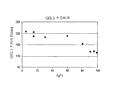
Figure 14 is for showing the Ag/SiO that makes according to embodiment 8
2The figure of the particle size distribution that particle records through QELS.
Figure 15 (a) is for marking and drawing with Ag change of size SiO
2Coating thickness to Ag before figure and Figure 14 (b) of body burden for marking and drawing the SiO of 20nmAg particle
2Coating thickness is to the figure of the preceding body burden of silver.
Figure 16 marks and draws the figure of x x ray diffraction (XRD) crystalline size of the Ag in the end product to the weight % silver content in the end product.
Figure 17 is the figure of the weight % silver content in the plotting end product to the BET surface area of final granular product.
Figure 18 is the figure of the weight % silver content in the plotting end product to the size of silver-colored aggregation in the final granular product.
Figure 19 is the figure of the weight % silver content in the plotting end product to the density of final granular product.
Figure 20 is for marking and drawing weight % silver content in the end product to the figure of the average grain diameter through the final granular product that QELS measured.
Figure 21 (a) and (b) be the Ag/SiO that uses 95% weight Ag load to make according to embodiment 7 and in precursor mixture
2The TEM micrograph of particle.
Figure 22 is the TEM micrograph that uses the Ag/ZnO particle of 90% weight Ag load manufacturing according to embodiment 10 and in precursor mixture.
Figure 23 is according to embodiment 11 and in precursor mixture, uses AgNO
3Ag/SiO as silver-colored source and 99% weight Ag load manufacturing
2The TEM micrograph of particle.
Figure 24 is for containing 55 weight %Bi
2O
3, 23 weight %B
2O
3, and the TEM micrograph of the glass powder particles of 22 weight %ZnO.
Figure 25 is for containing 99 weight %Ag and 1 weight %SiO
2The TEM micrograph of silver-silicon dioxide nanocomposite.
Figure 26 is for containing 99 weight % galactic nucleus and 1 weight % shell (55 weight %Bi
2O
3, 23 weight %B
2O
3, and 22 weight %ZnO) the SEM micrograph of nano-complex.
Embodiment
The present invention relates to the method that forms the photovoltaic conductive component in one embodiment, comprising:
(a) composition is deposited at least a portion of substrate, wherein said composition comprise have about 10 nanometers~less than the primary particle diameter of 500 nanometers and contain continuously or discrete ceramic material coating contain metallic particle; (b) the said composition of heating makes precursor composition form at least a portion of photovoltaic conductive component.In some embodiments, the nano particle that contains metal of pottery coating is with the manufacturing of single step vapor phase method.
Contain metallic particle
The particle that is used to make photovoltaic conductive component of the present invention has core/shell structure, and its center is made up of metal or metal alloy and shell is made up of ceramic material.Said particle can be used as the independent metallic particle that contains that has discrete continuous or discontinuous ceramic material coating separately and exists, and/or said particle can be used as, and a plurality of aggregations that contain metallic particle exist in common ceramic particle matrix.Like what below will discuss in more detail, depend on the relative quantity of metal and ceramic precursor in the charging of gas-phase synthesizing method as aggregation and/or as the independent character that contains metallic particle of particle.In some embodiments, contain the metallic particle that contains that metallic particle is a crystal.
In fact metal in the particle can comprise the metal of any type and can comprise single metal and metal alloy.Special preferred metals is drawn together following at least a: palladium (Pd), silver (Ag), nickel (Ni), cobalt (Co), copper (Cu), gold (Au), platinum (Pt), molybdenum (Mo), tungsten (W), zinc (Zn), ruthenium (Ru), titanium (Ti) etc.Typical alloy comprises that the Ag/Pd alloy for example has about 70: 30 Ag: the Ag/Pd alloy of Pd ratio, and Cu/Ni, Cu/Zn and Pd/Pt alloy.Preferably contain and at least aly in palladium, silver, nickel, copper, gold and the platinum contain metallic particle and even more specifically for containing at least a those in palladium, silver, nickel and the copper.Most preferably, said metal is silver or silver alloy.
Similarly; The selection of ceramic material is not narrow limited; Although ceramic material condenses generally under the temperature higher than metal in the gas-phase synthesizing method therein, apparent surface's wetting property of metal and pottery should make allows along with metal condenses in the superficial layer of the redistribution of pottery metal of last time with the nuclear that forms final particle.Usually the ceramic case material comprises oxide, for example following at least a oxide: silicon, zirconium, titanium, aluminium, cerium, zinc, tin, bismuth, molybdenum, manganese, vanadium, niobium, tantalum, tungsten, iron, chromium, cobalt, nickel, copper, yttrium, bismuth, magnesium, thorium, ruthenium and gadolinium.In some embodiments, said ceramic material comprises the mixture of multiple metal oxide.In other embodiments, said ceramic case material comprises two kinds or more kinds of oxides of silicon, zirconium, titanium, aluminium, cerium, zinc, tin, bismuth, molybdenum, manganese, vanadium, niobium, tantalum, tungsten, iron, chromium, cobalt, nickel, copper, yttrium, bismuth, magnesium, thorium, ruthenium and gadolinium.In some embodiments, said ceramic case material comprises the oxide of at least a element that is selected from lead, strontium, sodium, calcium, bismuth and boron.In some embodiments, said ceramic case material comprises two kinds or the oxide of more kinds of oxides of at least a element that is selected from lead, strontium, sodium, calcium, bismuth and boron.Some preferred oxides are silicon dioxide, titanium dioxide, zirconia, ceria and tin oxide, and preferred especially silicon dioxide.In all cases, these oxides can be doped with the doped chemical of low amount or a large amount, and wherein high doping content can cause forming tangible mixed-metal oxides phase.In some cases, the oxide as ceramic material can produce glassy shell on particle.Said oxide can be the composite oxides of being made up of two kinds or more kinds of elements, for example Y-Yb-O, Ba-Ti-O, Zn-Si-B-O etc.And multiple other ceramic material can be used for making particle shell, for example: and carbide, like carborundum or titanium carbide; Boride is like titanium boride; And nitride, comprise silicon nitride and titanium nitride; Silicide is like titanium silicide; Oxynitride; Oxysulfide; And oxycarbide.
Depend on to metal core and the selected concrete material of ceramic case, compare that final particle can demonstrate enhancing or other functional with the nano particle of clad metal not.For example, oxide skin(coating) can be the partially transparent chromatograph, and final in this case metal/metal oxide particle can demonstrate the metallic reflection property combined with color.In addition, if use SiO
2As shell material, the method (for example silanization, give hydrophobic or hydrophilicity, add different parts, the improvement of surface acidity etc. to silica surface) that silica surface is handled in then various known being used to can be used for providing functional as the resistance to wear of the adhesion that strengthens, improvement and environmental resistance and curing (curing) time of reducing to particle.In some embodiments, particle is functionalized with one or more functional groups.In some embodiments, said functional group comprises silane, for example comprises the silane of HMDS.In other embodiments, said functional group comprises siloxanes, for example oxirane functional siloxane such as Gelest 2-methoxyl group (gathering inferior ethoxyl) propyl trimethoxy silicane.
The particle of execution modes more of the present invention (as independent particle or as the part of aggregation) has little domain, its have through X-ray diffraction (XRD) measure less than the size of 50nm and have about 10 nanometers of measuring through transmission electron microscopy (TEM)~less than 100 nanometers, about 10 nanometers~about 80 nanometers 10 nanometers~about 50 nanometers or about 20~about 60 nanometers primary particle diameter of 30 nanometers~about 50 nanometers according to appointment according to appointment usually.
In some embodiments, particle has about 10 nanometers~about 500 nanometers primary particle diameter of 10 nanometers~about 300 nanometers, about 10 nanometers~about 200 nanometers and about 10 nanometers~about 100 nanometers according to appointment.
In addition; In some embodiments; No matter be that metal or metal alloy farmland are tending towards demonstrating narrow particle size distribution as aggregation or independent existing through coated pellet, make the particle of at least 80 weight %, preferred at least 90 weight % have size less than 500 nanometers; Wherein said particle size distribution is used accurate electric light scattering, and (quasi-elastic light scattering QELS) is measured.In some embodiments, the said metallic particle that contains has and makes the particle of at least 90 weight % have less than 2 μ m for example less than the particle size distribution of 1 μ m size.In addition, in optional execution mode, saidly contain the particle that metallic particle comprises a spot of micron-scale.For example, said particle randomly have make at least 1 weight % for example the particle of at least 5 weight % or at least 10 weight % have particle size distribution greater than 1 μ m size.
In some embodiments; When said when containing metallic particle and being present in the powder as aggregation; Aggregation have usually less than 500 nanometers as less than 300 nanometers for example less than 200 nanometers, in some cases less than 100 nanometers with less than the weight average particle diameter of 50 nanometers; Wherein aggregate size uses accurate electric light scattering (quasi-elastic light scattering, QELS) mensuration.In some embodiments, aggregation has the for example particle diameter of 75 nanometers~300 nanometers, 75 nanometers~about 200 nanometers or 100 nanometers~500 nanometers of 75 nanometers~500 nanometers.Usually, each aggregation comprise each aggregation on average less than 20 for example on average less than 10 as on average less than 5 the said metallic particle that contains.
Since their small size, aggregation be preferably can ink-jet and need not to pulverize.Usually, aggregation comprise each aggregation on average less than 20 for example on average less than 10 for example on average less than 5 the said metallic particle that contains.
In some embodiments; No matter said particle is independent to contain metallic particle and/or a plurality of aggregations that contain metallic particle in the matrix of general ceramic material through what coat; The volume ratio of metal and ceramic material is generally at least 9: 1 (90 volume % metals/10 volume % pottery) in each particle, for example at least 19: 1 (95 volume % metals/5 volume % pottery) and at least 98: 1 (98 volume % metals/1 volume % pottery).The result; The thickness of cramic coat extremely thin usually (usually less than 10 nanometers); Make under the situation of the preferred implementation of the silver-colored particle of coated with silica; Though coating plays the effect that prevents particle agglomeration, by the film of particle manufacturing be reflexive and high silver concentration (>95% weight) down particle conduct electricity.
Gas phase is synthetic
Employed particle can pass through the one-step method manufacturing in the method for the present invention; Metal/alloy nuclear and precursor vaporized cramic coat that wherein in the pyroreaction zone, makes nano particle lets devaporation/nucleation to form the nano particle of expecting to form ceramic steam and metal/alloy steam then.Usually, ceramic material has than the high boiling point of metal/alloy and suppose that therefore it condensed before metal component from steam.Although do not receive any concrete theory constraint, think that the metal/alloy steam condenses as the metal/alloy nano-cluster then on established ceramic particle.Yet, under related high temperature, think metal/alloy be highly movably and particle reset and to be the preferred form of thermodynamics, wherein than the low-surface-energy ceramic composition as existing at the outside coating that contains on the nano particle of metal.
Term " precursor " refers to comprise at least a composition that is included in the component in the nano particle." component " refers at least some parts confirmed of precursor, and it becomes a nano particle part.For example, when whole compositions were included in the nano particle, said component can be whole compositions of precursor.For example, in one embodiment, ceramic material self gasifies and contacts with the steam of metal/alloy precursor.Yet more frequently, said component is that the whole compositions than precursor lack, and can be merely be present in that precursor is formed and nano particle in the formation element.For example; It often is such situation: precursors decompose in the pyroreaction zone; Then a kind of in the catabolite or more than a kind of element said catabolite further reaction or further reaction become the part of nano particle down, perhaps metal oxide coating of metal/alloy nuclear for example.
Precursor can be in the pyroreaction zone gasification or has gasifiable intermediate and if necessary decompose with the pottery that produces expectation and the arbitrary substance of metal/alloy steam.Under the situation of metal/alloy component, precursor is generally one or more and may be dissolved in the slaine in the liquid vehicle (vehicle).Such salt can comprise simple inorganic acid salt for example nitrate and chloride.Yet; The pyroreaction zone is in the preferred implementation of a flame reactor part therein; Can expect to use precursor such as metal carboxylate, metal alkoxide or other organic derivative of one or more acylate forms, make that precursor is that flame reactor provides at least a portion fuel.Similarly, organic derivative can be used as the precursor of ceramic case, and when making that for example ceramic case is silicon dioxide, suitable precursor comprises HMDO.
In carry out this synthetic method, find that the volume ratio of metal precursor and ceramic precursor is important for the expectation nano particle that manufacturing comprises the metal core of being surrounded by ceramic case.Accurately than depending on employed concrete metal and pottery, but the volume ratio of finding metal and pottery in the precursor mixture usually should be at least 4: 1, as at least 9: 1, and for example at least 19: 1, at least 47: 1 or at least 98: 1.
Usually, precursor is incorporated in the pyroreaction zone with on-gaseous.More properly, when being incorporated in the reactor, precursor will for or part for to one or more of liquid, solid or the supercritical fluid charging of reactor.In a suitable enforcement, precursor is included in the discrete state material of on-gaseous and for example is ejected in the drop in the internal reaction device volume (internal reactor volume).
One preferred embodiment in; The gasification of metal/alloy precursor and ceramic precursor realizes through following: precursor is dispersed in one or more liquid vehicle; Liquid vehicle atomizing is contained the aerosol of precursor with generation, then aerosol is incorporated into the pyroreaction zone as by in plasma reactor or the pyroreaction zone that more preferably produced by flame jet or laser reactive device.Usually the pyroreaction zone be at least 1000 ℃, like at least 1500 ℃, at least 2000 ℃ temperature for example.Usually, the higher temperature in the conversion zone helps the formation of big nano particle.
The precursor of metal/alloy nuclear can be dispersed in the liquid vehicle identical with the precursor of pottery nuclear or precursor can be dispersed in the different liquid medium.And; Can each precursor be dispersed in its liquid vehicle through precursor portions ground perhaps is dissolved in the medium fully; Perhaps alternatively can precursor be dispersed in its liquid vehicle slurry or emulsion as the solid precursor particle; Make that after atomizing, the aerosol that is produced comprises the drop that contains precursor granules.
Liquid vehicle can be organically, water-based or organic/aqueous mixture.The more vectorial limiting examples of organic liquid comprise alcohol (for example methyl alcohol, ethanol, isopropyl alcohol, butanols), organic acid, glycol, aldehyde, ketone, ether, wax or fuel oil (for example kerosene or diesel oil), toluene and gasoline.Except organic liquid or replace organic liquid, liquid vehicle can comprise inorganic liquid, and said inorganic liquid is normally based on water-based.Some limiting examples of such inorganic liquid comprise the water and the aqueous solution, and it is neutral, acid or alkalescence that it can be pH.Said liquid vehicle can comprise the mixture of intersolubility liquid component, the mixture of the organic liquid (like some alcohol, ether, ketone, aldehyde etc.) that dissolves each other like the mixture of intersolubility organic liquid or water and one or more and water.Perhaps, liquid vehicle can comprise a plurality of tangible liquid phases, and emulsion for example is like oil-in-water type or water-in-oil emulsion.
Except the carrier that serves as precursor, said medium can have multiple other function.For example, when the pyroreaction zone was flame reactor a part of, liquid vehicle can be or can comprise as the flame combustion of the flame reactor component with fuel or oxidant.This fuel in liquid or oxidant can be main or postcombustion or the oxidant that is used to order about flame combustion.
When being incorporated in pyroreaction zone as the aerosol in liquid vehicle precursor, one preferred embodiment in, aerosol droplets is dispersed in the gas phase.Said gas phase can comprise the combination in any of the gas component of any concentration.Said gas phase can only be included in the reactor to (being non-reacted) component of inertia or said gas phase can comprise one or more reactive component (promptly in reactor, decomposing or otherwise reaction).When in flame reactor, producing the pyroreaction zone, gas phase can comprise that flame combustion is with fuel gas and/or oxidant.The limiting examples of suitable gaseous oxidizer be gaseous oxygen (its can through from air, make gas phase or through comprising that air provides) and carbon monoxide.The limiting examples that can be included in the fuel gas in the gas phase comprises hydrogen and gaseous organic substance such as hydrocarbon (like methane, ethane, propane, butane).Usually, gas phase comprises oxidant (being generally airborne oxygen) and the fuel that is delivered to flame individually at least.Perhaps, gas phase can comprise premixed fuel and the oxidant that is used for flame combustion.And gas phase can comprise and contains the admixture of gas that surpasses a kind of oxidant and/or surpass a kind of fuel.And gas phase can comprise and is used for a kind of of nano-particle material or more than a kind of gaseous precursors.For example, when ceramic case comprised oxide material, gaseous precursors can be oxygen-containing gas, like air.
Precursor is being incorporated under the situation in the pyroreaction zone as the aerosol in liquid vehicle, can using anyly to become the appropriate device of drop such as spray nozzle to make said aerosol liquid dispersion.The instance of suitable spray nozzle comprises ullrasonic spraying mouth, multithread spray body mouth and pressure atomization mouth.An instance of suitable multithread spray body mouth is shown among following Fig. 5 that goes through-6.
The ullrasonic spraying mouth vibrates liquid crushing is become the piezoelectric of droplet produce drop through using under supersonic frequency.Pressure atomization mouth working pressure and separator (separator) or sieve (screen) are to become drop with liquid crushing.In some cases, pressurized nozzles can relate to and uses some steams that produce from liquid self with the liquid pressurization be broken into drop.Using ultrasonic and advantage pressurized nozzles is not need extra fluid to produce drop.This precursor that is dissolved in the liquid vehicle therein be responsive and/or with the inconsistent situation of in multithread spray body mouth, using of other common fluid under can be useful.
Except using spray nozzle to be used for the dispersing liquid medium, in producing step, also can use any other to be used to produce the appropriate device or the equipment of dispersant liquid drop.An instance that can be used for producing the device of drop is a ultrasonic generator.Ultrasonic generator uses transducer so that liquid vibrates under very high frequency, and it makes liquid crushing become drop.An instance of the ultrasonic generator that can use with the present invention is disclosed in United States Patent(USP) No. 6,338, in 809, its full content is incorporated herein by reference.Another instance that can be used for producing the device of drop is the high energy atomizer, those that for example in production of carbon black, use.
One preferred embodiment in, use flame reactor to make nano particle through coating." flame reactor " refers to have the reactor of internal reaction device volume, and said internal reaction device volume perhaps surpasses a flame through one and directly heats when reactor moves." directly heating " refers to that the hot driving of flame flows in the said internal reaction device volume.Term " flame " refers to luminous combustion zone.
Each flame of flame burner is produced by burner usually, through this burner oxidant and fuel supply flame is used for burning.Burner can be any suitable design that is used to produce flame, although the geometry of flame and other character receive the influence of burner design.The U.S. Patent application No.11/335 that submits on January 20th, 2006; Gone through the burner design of the certain exemplary that can be used for producing the flame that is used for flame reactor among 727 (the attorney docket 2005A004.2), the full content of this application has been incorporated herein by reference.Each flame of flame reactor can any desired mode be orientated.Some limiting examples of flame orientation comprise that horizontal-extending, vertical extent perhaps extend with some intermediate angle between vertical and level.When flame reactor had a plurality of flame, some of flame perhaps all can have identical or different orientations.
Each flame of flame reactor is usually with to light oxidant and fuel related with the incendiary source that produces flame.In some cases, incendiary source is one or more pilot flame, its except the initial point burning things which may cause a fire disaster is provided so that oxidant and fuel takes fire, the continuous igniting/energy source of the flame of keeping flame reactor can be provided also.Pilot flame can perhaps be produced by different fuel and/or oxidant by the identical oxidant and the fuel generation that are used to produce main flame.For example, when using identical fuel, can use flows through be used to produce flame reactor flame multicenter combustor a passage little fuel stream and produce pilot flame.Said little fuel stream can or can consume oxygen from surrounding environment to produce pilot flame with the oxidant premixed.Incendiary source is not limited to pilot flame, and incendiary source can be spark or other incendiary source in some cases.
And; Each flame (for example has multiple character; Flame geometry, Temperature Distribution, flame inhomogeneities, flame holding), it receives the influence of the factor of the character of for example burner design, burner charging and the geometry that flame is positioned at cover (enclosure) wherein.
An importance of flame is its geometry, perhaps the shape of flame.Some geometries are tending towards providing flame characteristics more uniformly, and this promotes to make the nano particle with relative homogeneity matter.A geometric shape parameters of flame is that it is at the shape of cross section of flame base perpendicular to the flow direction that passes flame.This shape of cross section receives the very big influence of burner design, although the influence that this shape also receives among geometry that other factors for example covers and the flame and fluid on every side flows.Other geometric shape parameters comprises the length and the width characteristics of flame.In this article, the length of flame refers to the longest dimension of flame on flow direction is vertical, and flame width refers to the longest dimension perpendicular to the leap flame of flow direction.About the length of flame and width, broad, larger area flame have the potential of the more uniform temperature of crossing over flame, because with respect to the gross area of flame, the edge effect of flame perimeter reduces.
Except helping to control the flame profile of Temperature Distribution, also may command is incorporated into the charging in the flame.An instance of important control parameter is the ratio that joins fuel (for example liquid vehicle) and oxidant in the flame.In some embodiments, be incorporated into the precursor oxidation easily in the flame, and can expect that ratio that the ratio with fuel and oxidant remains rich fuel is to guarantee not having excessive oxygen to be incorporated in the flame.The environment of rich fuel guarantees that all are incorporated into the oxygen burning in the flame and in flame reactor, do not have available excess of oxygen to come oxidation nanometer particle or precursor.In other words, in charging, have stoichiometric oxygen, the completing combustion that it promotes the fuel of all existence does not remain excessive oxygen thus.In other embodiments, can expect to have the Fuel-to-Oxidizer Ratio of oxygen enrichment.For example, when making metal oxide ceramic, can expect to keep in the flame with flame reactor in environment have excess of oxygen.
Except the environment in flame and flame reactor, Fuel-to-Oxidizer Ratio is also controlled the others of flame, for example flame temperature.If Fuel-to-Oxidizer Ratio is the ratio of rich fuel, then flame reactor will contain unburned fuel.Unreacted fuel is created in such as fruit and offers the flame under the low temperature of all fuel combustions of reactor.Unburned fuel also can be introduced the carbon contamination thing in the product particle.Therefore, expectation therein make all fuel combustions so that the temperature maintenance of flame under those situation of high-temperature, expectation provides excessive oxidant to guarantee to make all fuel combustions that offer flame or flame reactor to flame reactor.Yet, if expectation with the temperature maintenance of flame in lower temperature, fuel and the ratio of oxidant can be the only fuel combustion of a part that makes of rich fuel, make flame be no more than desired temperature.
Join the speed of the total amount decision of fuel and oxidant in the flame through the gas of burning, this is controlling the time of staying of formed primary granule in the flame again.The time of staying in flame of said primary granule determines the product particle diameter and determines the form of product particle in some cases.Comparing of oxygen and fuel also determines the concentration of particle in the flame, and this determines final product particle diameter and form again.More weak flame will make particle less or less gathering.
The particular type of fuel also influences the temperature of flame.Except the temperature of flame, the selection of fuel can relate to other consideration.The fuel that is used to burn and produces flame can be gaseous state or on-gaseous.The fuel of on-gaseous can be liquid, solid or the two combination.In some cases, the fuel of burning formation flame also can play the solvent of precursor.Such advantage is that precursor is surrounded by fuel in each drop, and it provides the optimum condition of precursor conversion when burning.In other embodiments, liquid fuel can be used as the solvent of precursor, but does not contain enough energy to be created in institute's calorific requirement that all must react in the flame reactor.In this case, liquid fuel can replenish with another liquid fuel and/or fuel gas, and said another liquid fuel and/or fuel gas burning are to contribute extra heat to flame reactor.The limiting examples of the fuel gas that can use with method of the present invention comprises methane, propane, butane, hydrogen and acetylene.Some limiting examples of the liquid fuel that can use with method of the present invention comprise alcohol, toluene, acetone, isooctane, acid and than heavy hydrocarbon such as kerosene and diesel oil.
An enthalpy of combustion that standard is a fuel that can be used for the selection of gaseous state and non-gaseous fuel.The ability that the temperature of the enthalpy of combustion decision flame of fuel, relevant flame speed (it influences flame holding) and fuel combustion totally and not form carbon granule.Usually the fuel of higher enthalpy produces and helps forming the flame of the higher temperature of nano particle greatly.
In some cases, fuel is the combination of liquid, and it can expect dissolving in precursor dissolves in as the liquid of low energy fuel the time.In this case, low energy fuel (for example, liquid vehicle) can be used for dissolving precursor, and the fuel of other higher-energy can be replenishing in flame reactor, to produce essential heat of low energy fuel.In some cases, two kinds of liquid fuels can be not solvable fully in each other, and liquid will be the multi-phase fluid (that is emulsion) with two phases in this case.Perhaps, can two kinds of liquid fuels be incorporated into (for example, under the situation of multithread body nozzle) the flame discretely from the conduit that separates.In other cases, two kinds of liquid can be dissolve each other each other and form single-phase.It should be noted that in other cases to have the liquid fuel that surpasses two kinds to be incorporated in the flame, said liquid can be in each other completely soluble or can be the form of emulsion.
Be used to make fuel combustion to can be gaseous oxidizer or on-gaseous oxidant with the oxidant that forms flame.The on-gaseous oxidant can be liquid, solid or the two combination.Yet preferably said oxidant is gaseous oxidizer and randomly comprises oxygen.Oxygen can not have basically other gas ground for example basically pure oxygen gas flow be incorporated in the flame reactor.In other cases, the mixture of oxygen with other gas such as nitrogen is incorporated in the flame reactor, situation is like this when using air.Though preferably have gaseous oxidizer, oxidant can be liquid in some cases.Some instances that can be used as the liquid of oxidant comprise inorganic acid.And, be incorporated into the combination that oxidant in the flame reactor can be gaseous oxidizer or liquid oxidizer.When expectation lets the on-gaseous precursor be dissolved in the liquid so that its dispersion and when also expectation lets oxidant very near the on-gaseous precursor when in flame reactor can be this situation.In this case, can precursor be dissolved in the liquid flux that plays the oxidant effect.
From the discharge stream via flow passage of each flame of flame reactor or the inner track of conduit, pass flame reactor.Used " conduit " refers to pass the restricted access that is used for conveyance fluid of flame reactor among this paper.When flame reactor comprises a plurality of flame, can flow into the independent conduit that is used for this flame or be used for from the shared conduit of the discharging that surpasses a flame from the discharging of any given flame.But the circulation of finally flowing from each flame is everlasting and before the flame reactor discharging, is incorporated in the single conduit.
The conduit that passes flame reactor can have and can be used for multiple shape of cross section and the area that fluid flows, and some unrestricted instances comprise circle, ellipse, square or rectangle.Yet, as a rule, preferably have the conduit of circular cross section, because can producing the unwanted of deposition that can promote on catheter surface, the existence of sharp corner or acute angle flows or flow disturbance.Catheter wall can be processed by any material that is suitable for tolerating the temperature and pressure condition in the flame reactor.The character of fluid of flame reactor of flowing through also can influence the material chosen of the used structure in any position in the reactor.Yet temperature normally influences the most important variable that the catheter wall material is selected.For example, for being up to about 1200 ℃ temperature, quartz can be suitable material, and for being up to about 1500 ℃ temperature, the possible material of conduit comprises aluminium oxide, mullite and carborundum.As another instance, for being up to about 1700 ℃ treatment temperature, graphite or graphited pottery can be used for tube material.
Precursor is incorporated in the zone very hot in the flame reactor (being also referred to as the first area among this paper), and said zone enough heat makes that the material of all these first area parts of flowing through is in gas phase basically.Precursor can enter into gas phase through any mechanism.For example, precursor can gasify simply, and perhaps one or more precursors can decompose the component that produces final nano particle, and this component gets into gas phase as the part of catabolite.Yet along with particle nucleation and growth take place, this component is left gas phase at last.This component can comprise along with what temperature reduced from removing of gas phase simply condenses, and perhaps can comprise other reaction.For example, residual gasification precursor can react on the surface that becomes nuclear monomer through any surface reaction mechanism.
Growth step begins and owing to than granule collision and agglomeration with sinter bigger particle into and continue or continue to add in the nano particle of growing through other material is joined the flame reactor from the particle nucleation.The growth of nano particle can relate to and the interpolation material that has been present in the material same type in the nano particle, perhaps adds the flux (flux) of fusion (fusing), sintering and/or coalescence that different materials for example promotes nano particle.Depend on the temperature and the time of staying in the reactor first area, particle can fully fuse when condensing to form independent ball or they and can partly fuse to form hard fractal (fractal) shape aggregation.Usually, improve the particle diameter increase that temperature and the time of staying in the flame reactor make nano particle.Similarly, the concentration that improves precursor in the liquid vehicle is tending towards causing the size of the increase of nano particle.
When making minimum particle, growth step can most ofly perhaps fully take place in the first area of flame reactor after flame immediately.Yet, when expecting bigger particle diameter, can be except the processing the processing in the first area that occurs in flame reactor.The weight average particle diameter that makes nano particle " growth " refer to increase nano particle used herein.At least the part growth step will be randomly carries out in the volume of the flame reactor in downstream, first area, in its weight average particle diameter scope that is suitable for better making nano particle controllably grow to expectation.This downstream part of flame reactor is called second area in this article so that itself and above-mentioned first area are distinguished.As a rule, said first area is the hottest part in the flame reactor.
The comparable first area of the time of staying or the time of staying in the thermal region of the nano particle stream of growing in the second area are long.Term " time of staying " refers to that flow is retained in the time span in the specific region (for example, first area or second area), and it is based on the average flow speed of passing said zone and the geometry in said zone.For example, flow has the time of staying in following scope, the upper limit that this scope has the lower limit that is selected from 1ms, 10ms, 100ms and 250ms and is selected from 500ms, 400ms, 300ms, 200ms and 100ms usually in first area (and flame).In one embodiment, the time of staying of flow is at least 2 double-lengths, 4 double-lengths, 6 double-lengths or 10 double-lengths of the time of staying in the first area in second area.Therefore, in the second area time of staying of flow usually in following scope, the upper limit that this scope has the lower limit that is selected from 50ms, 100ms, 500ms, 1 second and 2 seconds and is selected from 1 second, 2 seconds, 3 seconds, 5 seconds and 10 seconds.In one embodiment, the total residence time of first area and second area in following scope, the upper limit that this scope has the lower limit that is selected from 100ms, 200ms, 300ms, 500ms and 1 second and is selected from 1 second, 2 seconds, 3 seconds, 5 seconds and 10 seconds.
In the decision second area in suitable time of staying of nano particle; Several considerations; The number concentration (that is the nano particle quantity of per unit volume flow) that comprises nano particle in melt temperature (and sintering temperature), the temperature in the second area and the flow of material in the weight average particle diameter, nano particle of expectation.
Number concentration about the nano particle of the second area of flowing through; If this number concentration is enough big; Then nano particle will be tending towards colliding more continually, and growing faster for particle provides bigger chance, need realize the weight average particle diameter of expecting the less time of staying in second area.On the contrary, if the concentrations of nanoparticles in the second area is little, then not too frequent the and germination of the collision between the nano particle must be carried out more slowly.And, have specific nano particle number concentration (being called " characteristic number concentration " among this paper), be lower than the collision of this concentration particle become rare so that for practical purpose nano particle stop effectively because the growth of particle collision.For different weight average particle diameters, the characteristic number concentration is different.
If the temperature in the setting second area with the growth of the nano particle that promotes the collision through nano particle (promptly; Fusion is sufficiently high to form single nanoparticle for the collision particle), then the control of the number concentration of nano particle and the time of staying is two important control variables in the second area.Therefore, if the number concentration of nano particle in the second area is maintained particular concentration, then can change time of staying in the second area with the collision degree that realizes expectation to be implemented in the weight average particle diameter in the expected range.Yet, if set the time of staying, the weight average particle diameter that the number concentration of the nano particle in the may command second area makes realization expectation in the time of staying that sets.The control of weight average particle diameter can be for example through change precursor concentration or the two combination in temperature and the charging that changes the first area in the second area, or cross-sectional area through changing reactor and/or flame realize at the cross-sectional area at its width position place.In one embodiment, flame is preferably 0.01~0.25 at the cross-sectional area at its width position place and ratio at the cross-sectional area of the reactor at same position place.On the contrary; For the time of staying of setting in the second area and Temperature Distribution; Scalable is supplied with the concentration of on-gaseous precursor (and other precursor) of first area realizing the intended volume concentration in the second area, thereby realizes being used to expect the character volume concentrations of weight average particle diameter at least.
Temperature control in the second area of flame reactor is very important.The temperature maintenance of second area can be comprised that in the temperature range of specific rising maintenance has been present in the heat (waste heat of flame in for example, from the first area) in the flow.This can for example realize with the higher temperature that keeps passing second area to reduce thermal loss through a whole or part that makes the conduit that passes second area is adiabatic.Except making the second area thermal insulation or be used for replacing making second area adiabatic, can add heat to second area and distribute with the desired temperatures of keeping in the second area.
With the temperature maintenance in the second area is that the material that is lower than nano particle will gasify or the temperature of thermal decomposition, but is higher than the sintering temperature of the metal and/or the ceramic composition of nano particle." sintering temperature " refers to that coherent collision nano particle fuses the minimum temperature that forms new primary granule in the time of staying of second area.Therefore, the sintering temperature of nano particle depends on the time of staying of nano particle in material and the second area in the nano particle and the size of nano particle.The growth of nano particle therein comprises in those execution modes through the remarkable growth of particle collision, should nano particle maintained the sintering temperature place in the second area and preferably be higher than this sintering temperature.
In some cases, the flow that contains nano particle was contacted before getting into second area in this flow with hardening media and reduce its temperature.Hardening media is in the temperature lower than flow, and when mixing with flow, it reduces the temperature of flow, and the temperature of the nano particle in the flow is reduced.This quenching step can reduce the temperature of nano particle the amount of any desired.For example, can make of the speed reduction of the temperature of flow with about 500 ℃/s~about 40000 ℃/s.In some enforcements, the temperature that can make flow is with about 30000 ℃/s, perhaps about 20000 ℃/s, perhaps about 10000 ℃/s, the perhaps perhaps speed reduction of about 1000 ℃/s of about 5000 ℃/s.
Hardening media preferably includes quenching gas.Quenching gas can be after in being incorporated into flame reactor non-reacted and can introduce the temperature that is used to reduce flow individually.For example when expectation stops the growth of nano particle through further collision, can be this situation.The quenching step is through helping that as follows further growth is stopped: making the flow dilution, the frequency of particle collision is reduced, and reduce temperature, reduce the collision particle thus and fuse together to form the possibility of new primary granule.When expectation stopped further germination, the flow through cooling of leaving the quenching step should be preferably lower than the sintering temperature of nano particle.Can collect then through the nano particle-promptly of cooling and the gas phase separation of flow.
The special properties of maintenance nano particle when the quenching step also is used in nano particle and in flow, has formed with nucleation.For example, if nano particle has been used for final specific phase nucleation and formation of using with expectation, the step of then quenching can help to keep this expectation phase, if do not quench then this expectation perhaps changes recrystallization into different crystalline phase.In other words, if hope to make the nano particle specific crystal structure maintenance of nucleation and formation, the step of then quenching can be used for making the recrystallization of nano particle to stop.Perhaps, quenching gas can be non-reacted, but is not intended to nanoparticle growth is stopped, but replaces only reducing temperature to adapt to some further processing that take place at a lower temperature.
As another option; Quenching gas can be reactive because it comprise one or more in flame reactor for reactive or become reactive (for example with the material of nano particle or with flame reactor in some components in the gas phase of flow be reactive) component.As an instance, quenching gas can comprise the precursor of the additional materials in the nano particle to be added.Said precursor can perhaps can not carry out any reaction before nano particle contribution material, in the quenching zone, reacting.In a concrete instance, quenching gas can contain oxygen, the metal reaction in itself and the nano particle with the generation that promotes metal oxide in the nano particle or its can with contained carbon reaction in the nano particle to be translated into CO
2Mutually preferred with the non-thermodynamics of generation through dynamics Controlling, quenching also to help the generation of metastable phase.
Usually hardening media is incorporated in the quenching zone in next-door neighbour downstream, first area in the flame reactor.Yet, also can be through for example introducing hardening media and pass burner and hardening media is incorporated in the first area around precursor spout (jet) through suitably designing spray nozzle.This provides around the cooling of main burner flame " involucrum (envelop) ".Perhaps, hardening media can be incorporated into the center of burner and can be surrounded by flame.This allows that core from flame is to flame hardening.Finally, the combination of two kinds of methods can be used for inside and outside cooling flame more than.
In other embodiments, can expect to provide sheath (sheathing) medium, it surrounds the flame that produced by flame reactor at least in part to realize following at least one: (a) make the flame cooling; (b) promote the product nano particle to pass flowing of flame jet system; (c) cooling is positioned at flame any metal surface on every side; (d) prevent in the internal reaction device volume that surrounds burner and/or flame, to form turbulent region; (e) allow extra material such as oxidant or extra precursor medium are caused flame and/or internal reaction device volume.Usually, the sheath medium comprises gas, like oxygen, nitrogen, air, exhaust gas recirculation or water vapour.In another embodiment, said sheath medium further comprises atomized water.If said sheath medium comprises atomized water, then this sheath medium randomly comprises the atomized water of about 10~about 100 volume % for example about 50~about 100% or about amount of 90~about 100%, based on the cumulative volume of sheath medium.
Can control the size and the agglomeration of metallic particles through the size of controlling the ceramic particle that in flame, forms at first.Because the much lower vapour pressure of the high vapour pressure of metal and pottery, thereby suppose that when metal still is the steam form the ceramic steam deposition that in flame, forms forms pottery solid particle.Ceramic particle will be grown through collision and agglomeration and had by the form of above-mentioned parameter decision and the primary granule or the aggregate particle of size with formation.At some some places of room and time, metal vapors will begin nucleation on the surface of already present ceramic particle, the formation of the metallic particles on this causes in the surface of ceramic particle/aggregation perhaps.Because height mobility, the phase counterdiffusion of metal/ceramic and the wetting property of metal/ceramic of metal under the high temperature; Thereby metal moves with metal oxide to nuclear with metal and to the mode that the appearance of new composite particles moves himself reset, and forms coated pellet.The size that is coated on the metallic particles in the pottery depends on concentration of metal in size and the reactor of initial ceramic particle/aggregation.Though the phase counterdiffusion of the interior metal of initial ceramic particle is strong under the high temperature, because the existence of pottery in appearance of aggregation, the metal diffusing between the ceramic particle/agglomerate that separates is very limited (perhaps not existing).Each ceramic particle/aggregation is the independent farmland on the space, and wherein metal can diffuse to form the spherical metal particle.Simultaneously, the effect of the obstacle of metal diffusing between the different aggregations is played on ceramic particle/farmland, otherwise this will cause the formation of much bigger metallic particles.
Desirably; Flame spraying of the present invention occurs in the flame jet system of sealing; The flame jet system of said sealing refers to that the flame jet system separates flame and its environment and can controllably import for example fuel/oxidant, precursor and liquid vehicle, makes the measurable and accurately control of this method.
With reference to accompanying drawing; An execution mode of the flame jet system of sealing is shown among Fig. 2; And comprise flame reactor 106, it comprises the tubular type conduit 108, burner 112 of circular cross section and produces and be arranged on the flame 114 in the tubular type conduit 108 by burner 112.Flame reactor 106 has very hot first area 116, and it comprises flame 114 and near the internal reaction device volume the next-door neighbour of flame.The charging 120 that will contain precursor medium is introduced directly in the flame 114 through burner 112.Can fuel that be used for flame 114 and oxidant be opened supply flame 114 in 120 minutes as the part of charging 120 and/or with charging.In preferred embodiment, preferably be present in the effect that liquid vehicle in the precursor medium plays fuel.
Randomly, the heat-insulating material (not shown) comprise second area 134 conduit 108 part and make this part adiabatic.In addition or alternatively, second area 134 or its part are surrounded by the heater (not shown), it is used for when flow is in said second area, heat being input to this flow.The additional heat of being added to second area 134 by heater provides control in second area, nano particle is maintained under the temperature of rising, and the temperature of said rising does not use the situation of heater high such as fruit.The flow that heater can be in second area provides any device of heat or the combination of installing.For example, heater can comprise one or more flame or can be heated by the flame or the heat-transfer fluid that circulates.In one embodiment, heater comprises along the heating region that can independently control of second area 134 length, makes that the different subregions (subzone) in the second area 134 can heat independently.For example when second area be when comprising the hot-wall tube furnace of a plurality of heating regions that can independently control, to can be this situation.
In the operating period of the flame jet system shown in Fig. 2, the charging 120 that will in liquid vehicle, comprise the precursor medium of metal core and precursor metal oxide shell is incorporated in the first area 116 through burner 112.Oxidant and fuel are also supplied with flame through burner 112 and are used for burning to keep flame 114.Oxidant and/or fuel can or be opened supplied burner 112 in 120 minutes with charging with charging 120.In first area 116, the physical chemical phenomenon of generation is following order: the burning of droplet evaporation, liquid vehicle and/or precursor, precursors reaction/decompositions, via the particle of nucleation form, through condense and the germination of sintering and metal from the surface of particle to the inversion of examining.Germination and metal are upside down in the second area 134 and continue then.
The improvement of the flame burner system shown in Fig. 3 and 4 displayed map 2, wherein the charging with precursor medium is incorporated in the first area 116 at the diverse location place.In Fig. 3, the end that flames 114 are pointed in charging 122 is incorporated in the first area 116, rather than passes through burner 112 like Fig. 2.In Fig. 4, contiguous but just exceeding the terminal position of flame 114 is incorporated into the charging 126 of on-gaseous precursor in the first area 116.
How Fig. 2-4 can be incorporated into the instance in the flame reactor if being merely precursor medium.Can the multiple charging of precursor medium be introduced in the flame reactor 106 in addition, different chargings is introduced in different positions, for example the charging 120,122 of Fig. 2-4 and introducing 126 time.
Referring now to Fig. 5-7, these have explained the flame atomizing nozzle assembly that is applicable to the flame reactor shown in Fig. 2-4.Spray nozzle assembly be shown usually 932 and comprise have outer wall 904, the columniform basically atomized feed nozzle 900 of near-end 924 and far-end 923.What longitudinal extension passed nozzle is: be arranged in the precursor feeds conduit 907 of central authorities, around conduit 907, extend and the atomizing medium feed conduit 908 of the annular coaxial with it and the isolated a plurality of fuel/oxidant feed conduits 909 in equal angles ground around atomizing medium feed conduit 908 and precursor medium feed conduit 907.Aptly, nozzle assembly also comprises one or more annular subsidiary conduit 934, and it is arranged between conduit 908 and 909 and is used for to reactor auxiliary material being provided.Although the shape of nozzle assembly can be the geometry (for example square and oval) of any appropriate, the shape of nozzle assembly is preferably columniform basically.
As shown in Figure 5, precursor medium feed conduit 907 has diameter δ, and atomizing medium conduit 908 has diameter γ, and fuel/oxidant conduit 909 has diameter ε.Precursor medium conduit 907 and atomizing medium conduit 908 separate with distance il, and each fuel/oxidant conduit 909 and precursor medium conduit 907 separate with distance lambda.The value of η must make and make the atomizing medium that the precursor medium that flows out the precursor medium conduit is flowed out the atomizing medium conduit atomize by precursor medium conduit 907 close enough atomizing medium conduits 908.The value of λ must make by the formed flame close enough of lighting of fuel/oxidant precursor medium conduit, make that precursor medium is lighted by fuel/oxidant flame during flame spraying.
According to the method for the invention, the value of δ control (i) is from the size of the precursor medium drop of precursor medium feed conduit outflow; But the (ii) amount of the precursor medium of flame jet (being output).The amount of the atomizing medium that the control of the value of γ can be flowed out from the atomizing medium conduit.The value control of ε is from the volume and the speed of the fuel/oxidant of fuel/oxidant conduit outflow.
In operation, fuel/oxidant 916 fuelings/oxidizer manifold 909 and its near-end 924 from nozzle assembly are flowed to far-end 923.When fuel/oxidant is left fuel/oxidant conduit 909 at far-end 923 places, for example it is lighted with extra pilot flame, form the directly flame of heating internal reaction device volume 921 thus.Simultaneously, atomizing medium 917 is supplied with atomizing medium conduit 908 and precursor medium conduit 907 respectively with precursor medium 918, and the near-end 924 from nozzle assembly flows through to far-end 923 under pressure.When atomizing medium and precursor medium were left the far-end 923 of nozzle assembly, atomizing medium made the precursor medium atomizing to form drop when precursor medium is incorporated into internal reaction device volume 921.Left the burnt fuel/oxidant mixture of conduit 909 subsequently lights through the precursor medium of atomizing.
In one embodiment, atomized feed nozzle 900 is surrounded and is in direct contact with it by the sheath medium nozzle supporting construction 919 that is limited inwall 912 and outer wall 913.Said sheath medium nozzle supporting construction comprises the sheath medium nozzle 915 of a plurality of longitudinal extensions basically.As shown, sheath medium nozzle supporting construction is formed by annular slab, wherein has the hole that limits sheath medium nozzle 915.Sheath medium nozzle 915 is communicated with sheath pressure medium ventilating system 920 fluids through sheath medium inlet 922.The sheath medium nozzle comprises that also the sheath medium can flow into the sheath media outlet 933 the internal reaction device volume from it.Sheath pressure medium ventilating system 920 is contained in the sheath pressure medium ventilating system shell (housing) within 927 that comprises inwall 926 and outer wall 925.The charging 929 of sheath medium gets in the forced air-ventilating system 920 via the inlet in the shell 927 928.
As shown in Figure 6, sheath pressure medium ventilating system inlet 928 preferably is positioned on the sheath pressure medium ventilating system shell 927, makes the sheath medium be incorporated in the sheath pressure medium ventilating system 920 along internal pressure ventilating system shell wall 926 tangentials.After it was introduced, the sheath medium was subsequently from flow through sheath media outlet 922 and enter into internal reaction device volume 921 of forced air-ventilating system 920.An advantage introducing the sheath medium along internal pressure ventilating system shell wall tangential is that it is allowed and passes evenly with stably distributing of sheath medium nozzle supporting construction and the sheath medium around flame.
Preparation of compositions
The employed composition of photovoltaic conductive component that forms some execution modes of the present invention can be printing ink or paste, depends on the employed method of deposition composition in substrate.Said composition preferably comprises the above-mentioned metallic particle that contains.In addition, said composition preferably comprises medium.Randomly, said composition also can contain one or more additives such as one or more dispersants.
Depend on prescription; Composition of the present invention can be useful in many different printing processes; Said method comprises for example silk screen, lithographic plate, intaglio plate, flexographic plate, photopatternable, syringe (syringe), aerosol injection, piezoelectricity, heat, drop on demand ink jet or continuous ink jet printing, the preferred ink jet printing or the printing of writing direct.Though highly depend on material and the concrete printing process of being implemented; But in various execution modes; Particulate load in the composition is at least about 2 weight % based on the total weight of total compsn, for example at least about 5 weight %, at least about 10 weight %, at least about 15 weight %, at least about 20 weight %, or at least about 50 weight %.Preferably; The total load of useful particle for not being higher than about 75 weight %, for example is not higher than about 40 weight % based on the total weight of composition, is not higher than about 20 weight %, is not higher than about 10 weight %, perhaps is not higher than about 5 weight % in the composition that is used to form photovoltaic conductive component of the present invention.In various execution modes; Aspect scope; Said composition comprises the metallic particle that contains based on about 1 weight %~about 60 weight % of composition total weight, for example about 2~about 40 weight % contain metallic particle, about 5~about 25 weight % contain metallic particle, or about 10~about 20 weight % contain metallic particle.In various other execution modes, said composition comprises and contains metallic particle, the metallic particles of for example about 40~about 60 weight % based on about 40 weight %~about 75 weight % of composition total weight.The load that surpasses preferred load can cause high viscosity of not expecting and/or the flow behavior of not expecting.Certainly, still provide the maximum load of useful consequence to depend on the density that contains metallic particle.In other words, for example, the density of metal that contains metallic particle is high more, and then by weight percentage the load that can accept and expect is high more.
Contain the metallic particle except said, said composition preferably also comprises medium.In one embodiment, these compositions further comprise anti-agglomeration material, for example above-mentioned polymer or surfactant.Used medium is preferably and can makes the liquid that contains the metallic particle stable dispersion in the composition.For example, preferably can provide at room temperature can keep a couple of days or even one, two, three weeks or month or even longer and do not contain the medium of composition of remarkable agglomeration and/or the sedimentation of metallic particle.For this reason, go back the preferred media thing and contain the surperficial compatible of metallic particle.In one embodiment, medium comprises one or more polar compounds (solvent) for example proton solvent or one or more non-proton non-polar component or their mixture (perhaps mainly being made up of it).In one embodiment, said medium is the solvent that is selected from alcohol, polyalcohol, amine, acid amides, ester, acid, ketone, ether, water, saturated hydrocarbons, unsaturated hydrocarbons and their mixture.
In some embodiments, said medium comprises the mixture of at least two kinds of solvents, the mixture of optional at least two kinds of organic solvents, the for example mixture of at least three kinds of organic solvents or at least four kinds of organic solvents.Use is preferred more than a kind of solvent, because it is especially allowed the multiple character of regulating composition simultaneously (for example viscosity, surface tension, with the contact angle of the substrate that will use etc.) and makes all these character as much as possible near optimum value.At for example United States Patent(USP) No. 4,877,451; 5,679,724; 5,725,647; 5,837,041; Disclose vectorial limiting examples in 5,837,045 and 5,853,470, its whole disclosures have been introduced this paper as a reference.In another embodiment, said medium comprises water, the optional water that mainly comprises.
In according to certain embodiments of the present invention, said composition has greater than about 5000cP for example greater than 7000cP with greater than the viscosity of 10000cP.Composition with above-mentioned viscosity is particularly useful in optional silk screen printing execution mode of the present invention.In other embodiments, said composition for example have less than about 100cP less than about 50cP, less than about 10cP, less than about 5cP with less than the viscosity of about 1cP.In other execution modes, said composition has the viscosity of the for example about 50cP of about 50cP~about 300cP~about 200cP and about 50~about 100cP.In some execution modes according to first aspect present invention, said composition has the surface tension of for example about 20 dyne of about 20 dyne/cm~about 60 dyne/cm/cm~about 40 dyne/cm.Viscosity and surface tension used among this paper are under 25 ℃.
Comprise the composition that contains metallic particle and randomly further comprise one or more additives; (ion, nonionic, anion, cation, zwitterionic surfactant contain the ion that comprises sulfate ion, sulfonate ion, carboxylic acid ion, phosphate anion, ammonium ion Huo person Phosphonium ion such as but not limited to buffer, polymer, resin (the for example ethyl cellulose solution of 20 weight % in terpineol), dispersant, thickener, adhesion promoter, rheology modifier, surfactant; The limiting examples of surfactant is two laruyl alcohol polyether phosphate sodium, 10 (sodium dilaurethphosphonate 10; DLP-10)), angle of wetting modifier, wetting agent are (for example; Glycerine, ethylene glycol, 2-Pyrrolidone and 1; The 5-pentanediol), crystallization inhibitor (for example, 29000MW PVP), adhesive, dyes/pigments etc.The limiting examples of adhesion promoter comprises lac, latex, acrylic acid ester, other polymer, metal or main group oxide (SiO for example
2, CuO).United States Patent(USP) No. 5,750 has been described the other instance of adhesion promoter in 194, and it is introduced this paper as a reference fully.The limiting examples of rheology modifier comprises SOLTHIX 250 (Lubrizol), SOLSPERSE 21000 (Lubrizol), styrene allyl alcohol (SAA), ethyl cellulose, carboxymethyl cellulose, celluloid, zinc-containing solid catalyst, ethyl celluloid etc.
The limiting examples of adhesive comprises latex, lac, acrylic acid ester etc.; In addition, such as but not limited to the for example copolymer of polyamic acid polymer, acrylic polymer, PVP, PVP (alkane, styrene etc.), gather fluoro esters of silicon acis polymer, gather fluorinated telomer and (comprise the Zonyl that E.I.Dupont deNemours & Co. makes
TMProduct) and the copolymer of styrene-acrylonitrile copolymer acids (for example can derive from Johnson Polymer Corp. with Joncryl
TMThose that trade name is sold) polymer can improve the bonding of metallic particles and/or metallicity nano particle and substrate, for example that kind that can accomplish of the material of coupling agent (for example zinc oxide, titanate esters and silane).These materials can function as follows: the interaction that increases the bonding of parts and substrate and reduce water and parts makes that thus parts are more durable.Gather promoter (cohesion promoter) in also can comprising in the printing ink to improve the reflectivity component durability.
The unrestricted instance of the dispersant that uses in polarity and the non-polar liquid body medium comprises: the copolymer of polymer, ion dispersant, non-ionic dispersing agent, copolymer, block copolymer, acrylic resin, styrene-acrylonitrile copolymer acid resin, styrene type dispersant, polyester, polyethers and Merlon, polyacrylic ammonium salt; The ammonium salt of styrene acrylic base polymer; Polymerization of carboxylic acid; The sodium salt of polymerization of carboxylic acid; The anion molecules surfactant, condense naphthalene sulfonic acids; Methyl hydroxyethylcellulose; Anion and non-ionic surface active agent; The polycarboxylic acids surfactant; Polyoxyethylene sorbitan fatty acid esters; The polyoxyethylene sorbitan monoleate; The polyoxyethylene sorbitan monostearate; The salt of polyfunctionality oligomer; Neopelex; The sodium salt of sulfuric ester or ammonium salt alkyl phenoxy gather (inferior ethoxyl) ethanol; The sodium salt of the polyelectrolyte of carboxylic acidization; Condense the sodium salt of naphthalene sulfonic acids; The sodium salt of disulfonic acid (disulohonic acid); The polyacrylic sodium salt of polyacrylic acid; The sodium salt of the alkyl naphthalene sulfonic acid of polymerization; The sodium salt of the alkyl-aryl sulfonic acid of polymerization; The sodium salt of the substituted alkyl-aryl sulfonic acid of polymerization; The sodium salt of the substituted benzene type alkyl sulfonic acid of polymerization; Sodium tetraborate; The ammonium salt of the polyelectrolyte alkylphenol b-oxide of carboxylic acidization; The condensation product of naphthalenesulfonateformaldehyde formaldehyde; The sulfosuccinate of the novolaks of condensation product alkoxide; Nonyl phenol novolaks b-oxide; The condensation product of cresols-formaldehyde-Schaeffer's salt (schaffer salt); The sodium salt of cresols-formaldehyde condensation products; Fatty acid methyl tarine (tauride) sodium salt; The phosphate of EO-PO-EO block polymer; 2,4,6-three (1-phenylethyl)-phenol polyethylene glycol ether phosphate; 2,4,6-three (1-phenylethyl)-phenol polyglycol ether phosplate triethanolamine salt; Three sec-butyl phenol polyethylene glycol ether phosphates with 4 EO; Alkyl polyglycol ether phosphate with 6 EO; Alkyl polyglycol ether phosphate with 8 EO; 2,4,6-three (1-phenylethyl)-phenol polyglycol ether sulfonic acid ammonium salt; The sulfosuccinate of the castor oil of ethoxyquin; Sweet mellow wine; NaLS; And list and disaccharides.EO-PO-acrylic polymer, sodium salt or ammonium salt.In some embodiments, said dispersant is selected from: polyacrylic ammonium salt; The ammonium salt of styrene acrylic base polymer; Condense naphthalene sulfonate salt; The sodium salt of the alkyl naphthalene sulfonic acid of polymerization; The phosphate of EO-PO-EO block polymer; The sodium salt of EO-PO-acrylic polymer; Ammonium salt with the EO-PO-acrylic polymer.In preferred embodiment, said dispersant comprises polyvinylpyrrolidone (PVP).
In some embodiments; Said composition comprises 1~20 weight % and contains metallic particle; (for example, 1~10 weight %, 5~20 weight % and 5~15 weight %), 0.1~5 weight % polyvinylpyrrolidone (for example, 0.1~1 weight %, 1~5 weight % and 2~5 weight %; Average MW=29000), 40~80 weight % water (for example; 40~50 weight %, 40~60 weight % and 50~80%), 0~50 weight % glycerine (for example; 0~20 weight %, 10~40 weight % and 20~50 weight %) and 0.01~1.5 weight %DLP-10 (for example, 0.01~1 weight %, 0.5~1.5 weight % and 0.9~1.5 weight %).
In addition, said composition can be randomly according to United States Patent(USP) No. 5,662,286; 5,624,485; 4,567,213; 4,390,369; 5,662,736; 5,596,027; 5,786,410; 5,643,356; 5,642, the method preparation described in 141 is introduced this paper as a reference with its full content.And, said composition can be randomly according to the method preparation described in the PCT application No.WO94/03546 that announces, its full content is introduced this paper as a reference.At last, said composition can be randomly according to european patent application No.EP0745479; EP0805192; Method configuration described in EP0745651 and the EP0952195 is introduced this paper as a reference with its full content.In optional execution mode, said composition can make water (40~80 weight %), glycerine (0~60 weight %), surfactant (0~10 weight through combination; DLP-10 for example) and buffer (0~2 weight %, for example ammonium hydroxide) preparation.Said composition also can randomly make water (84 weight %) through combination; 2-Pyrrolidone (2-pyrrolidinone) (2 weight %); Urea (0.2 weight %); Glycerine (2.1 weight %); Diethylene glycol (DEG) (7.5 weight %) and
 104E (0.2 weight %) preparation.Said composition also can randomly make water (85 weight %), 2-Pyrrolidone (2-pyrrolidinone) (2 weight %), glycerine (2 weight %), diethylene glycol (DEG) (2 weight %) and isopropyl alcohol (5 weight %) preparation through combination.
At low temperatures, the composition that contains metallic particle that comprises according to the present invention can deposit and be converted into the photovoltaic conductive component, can use multiple the have low relatively fusion or the substrate of decomposition temperature thus.Comprise according to the type of useful especially substrate of the present invention and to gather fluorinated compound, polyimides, epoxy resin (comprising the glass filling epoxy resin), Merlon and many other polymer.In some embodiments, substrate also can comprise based on cellulosic material for example timber or paper, acetic acid esters, polyester, polyethylene, polypropylene, polyvinyl chloride, acrylonitrile, butadiene (ABS), flexible fiber plate, nonwoven polymeric fabrics, cloth, metal forming and thin glass.Preferred especially substrate comprises the p-silicon wafer.
Photovoltaic conductive component: form and character
After on being deposited on substrate, handle, make said composition form at least a portion of photovoltaic conductive component comprising the composition that contains metallic particle.Said processing can comprise a plurality of steps, perhaps can in single step, take place, for example when said composition being heated rapidly and remaining under the conversion temperature capacity time when forming the photovoltaic conductive component.Can use stove, light source such as thermolamp and/or laser to realize heating.After the photovoltaic conductive component forms, can carry out reprocessing to it.For example, the degree of crystallinity of existing phase can for example increase through laser treatment.Said reprocessing also can comprise cleaning and/or encapsulation or other improvement of electronic unit.
In some embodiments, the processing that forms the photovoltaic conductive component comprises composition is heated to about 400 ℃~about 1000 ℃ for example about 700 ℃~about 1000 ℃, about 400 ℃~about 700 ℃ temperature in substrate, to form the photovoltaic conductive component.The heating of composition under said temperature causes and contains the metallic particle sintering, provides exceeding of metallic particles to ooze network thus.Therefore, the gained photovoltaic component not only comprises exceeding of metallic particles and oozes network, and comprises ceramic material.
In some embodiments, deposition photovoltaic conductive component in the substrate of the layer that comprises the silicon nitride layer on passivation layer for example such as the p-silicon wafer, it can be present in the ceramic material etching that contains on the metallic particle between the period of heating of said composition.In these execution modes, said photovoltaic conductive component comprises:
(a) ooze network with containing the exceeding of metallic particles that silicon base electrically contacts, said metallic particles comprises metal; With
(b) ceramic material.
The compositions and methods of the invention provide to form has the ability than the photovoltaic component of ceramic content low in the conventional photovoltaic conductive component.In a preferred embodiment, said ceramic material with less than 5 weight % for example less than 3 weight %, be present in the conductive component less than 2 weight % with less than the amount of 1 weight %.Because quite low ceramic content, the compositions and methods of the invention provide the ability of the photovoltaic conductive component of formation has improvement with respect to conventional photovoltaic conductive component conductivity.For example, in the preferred implementation of certain exemplary, the said resistance that oozes network of exceeding is less than 5 times metallic object resistance, for example less than 3 times, less than 2 times with less than 1.5 times metallic object resistance.In some embodiments, said exceeding oozes network and has less than 8 μ Ω cm for example less than 5 μ Ω cm or less than the resistance of 2 μ Ω cm.
In some execution modes according to second aspect present invention, said conductive component has greater than 1 μ m for example greater than the thickness of 5 μ m.Thick conductive component like this can for example print said composition through multipass and form.In other embodiments, said conductive component has the thickness of the about 50nm~for example about 50nm of about 1 μ m~about 200nm and about 100nm~about 500nm.In some embodiments, said conductive component comprises that one group refers to line and the afflux line that deposits with the right angle with respect to said finger line basically.When using some printing processes (for example, ink jet printing method), can form conductive component with quite thin live width.In some embodiments, for example, parallel finger line or afflux line or both have less than 200 μ m for example less than the width of 100 μ m.
The metal that is comprised in the photovoltaic conductive component of embodiment of the present invention randomly is selected from silver, copper, gold, palladium, platinum, nickel, cobalt, zinc, molybdenum, tungsten and their alloy.In some embodiments, metal is selected from ruthenium, titanium and alloy thereof.The ceramic material that is comprised in the photovoltaic conductive component to embodiment of the present invention is selected; Said ceramic material comprises the mixture of multiple metal oxide, and said metal oxide for example is selected from the oxide of at least a element of silicon, zinc, zirconium, aluminium, titanium, ruthenium, tin and cerium.In other embodiments, said ceramic material comprises two kinds or more kinds of oxides of at least a element that is selected from silicon, zinc, zirconium, aluminium, titanium, ruthenium, tin and cerium.In other execution modes, said ceramic material comprises the oxide of at least a element that is selected from lead, strontium, sodium, calcium, bismuth and boron.In other embodiments, said ceramic material comprises two kinds or more kinds of oxides of at least a element that is selected from lead, strontium, sodium, calcium, bismuth and boron.Preferably, said metal is a silicon dioxide for silver-colored and said ceramic material.
Purposes
Depend on employed metal and pottery, have various potential purposes through coated pellet described in this paper, be included in the purposes in optics, electronics, fuel cell and the above-mentioned photovoltaic application.
In one embodiment; Non-limiting purposes through coated pellet of the present invention comprises false proof and draws and use; The United States serial No.11/331 that for example submits on January 13rd, 2006,233, the United States serial No.11/443 that submits on May 31st, 2006,248, the United States serial No.11/443 that submits on May 31st, 2006; 264, the United States serial No.11/443 that submits on May 31st, 2006; 303 and the United States serial No.11/443 that submits on May 31st, 2006, those described in 304 are introduced this paper as a reference with all these documents.
In another embodiment; Non-limiting purposes through coated pellet of the present invention comprises that they are in electronics and electronics that can print and the purposes that shows in using; Like the purposes in conductor, resistance, dielectric, capacitor etc.; Purposes in for example various circuit, solar panel, plasma television, cellular phone, kneetop computer etc., as be described in the United States serial No.11/443 that for example submits on May 31st, 2006,131, the United States serial No.11/331 that submits on January 13rd, 2006; 231, the United States serial No.11/331 that submits on January 13rd, 2006; 186, the United States serial No.11/331 that submits on January 13rd, 2006,237, the United States serial No.11/331 that submits on January 13rd, 2006,190, the United States serial No.11/331 that submits on January 13rd, 2006; 239, the United States serial No.11/331 that submits on January 13rd, 2006; In 187 and the United States serial No.10/265 that submits on October 4th, 2002,179, all these documents are introduced this paper as a reference.
In another execution mode, the non-limiting purposes through coated pellet of the present invention comprises them as the purposes that is used for the eelctro-catalyst of fuel cells applications, the United States serial No.11/328 that for example submits on January 10th, 2006; 147, the United States serial No.10/417 that submits on April 16th, 2003,417, the United States serial No.11/081 that submits on March 15th, 2005,768, the United States serial No.11/081 that submits on March 15th, 2005; 765 and United States Patent(USP) No. 6,103,393,6; 660,680 and 6,967; Described in 183 those are introduced this paper as a reference with all these documents.
To further describe the present invention with reference to following non-limiting example now.
Embodiment 1-8
Neodecanoic acid silver and HMDO (HMDS) have the various Ag/SiO between 5/95 and 98/2 with the premixed in toluene of different amounts with manufacturing
2The test solution of weight ratio (seeing the following form 1).Each solution is dispersed in that the oxygen that flows with 40slpm disperses in the gas and offers and the similar flame reactor of reactor shown in Fig. 5-7 with 10ml/ minute speed.The incendiary source of reactor is made the pilot flame of fuel for the methane supplied with in order to 2slpm with the oxygen that 4slpm supplies with, and the fuel of burner is provided by precursor (neodecanoic acid silver and HMDO) and toluene carrier.In addition, reactor contains oxygen sheath that provides with 200slpm and the oxygen hardening media that provides with 900slpm.Nozzle head diameter (δ among Fig. 5) is 0.5mm.
Products therefrom is collected on bag house (baghouse) filter and uses transmission electron microscopy (TEM), scanning transmission electron microscope method (STEM), accurate electric light scattering, and (quasi-elastic light scattering QELS) is analyzed with other analysis to measure method.The result that the TEM of the product of embodiment 4-8 and STEM analyze is shown among Fig. 8-13.Find the Ag/SiO in the precursor mixture unexpectedly
2Than the character that influences end product significantly.For low Ag/SiO
2Precursor is than (being less than 20 weight % silver), and products therefrom is by the SiO that separates
2With Ag particle and some Ag/SiO
2The mixture of composite particles is formed.At higher Ag/SiO
2Precursor is during than (being greater than or equal to 60 weight %Ag), and product demonstrates unexpectedly and has the SiO of being encapsulated in
2The granule of Ag (20~60nm) the unique form in the coating.As shown in Figure 14, QELS proves higher Ag/SiO
2The product of ratio has near the relatively narrow particle size distribution of center 100nm, and does not have the particle greater than about 500nm basically.
Also find, can be through regulating Ag/SiO
2Ratio and treatment conditions control SiO
2The size of coating layer ranges in thickness and Ag particle.The layer thickness of coating and required SiO
2Relation between the coating material amount is shown among Figure 15 (a).Because silver (10g/cm
3) and silicon dioxide (2.2g/cm
3) between density variation, thereby need very little silica concentration to realize the covering basically of silver.This is shown among Figure 15 (b), wherein with compound Ag/SiO
2Silver concentration in the particle is to the coating thickness mapping of Ag nuclear particle with 20nm weight average particle diameter.The SiO that need be less than in this embodiment, 7% weight
2On 20nm silver particle, 1nm adhesion layer (coherent layer) to be provided.The diameter of galactic nucleus particle is big more, realizes that the required silica volume of the layer thickness of identical coating is few more.
Figure 16 explains that silver-colored load (in weight %) in the final granular product is to the influence of XRD crystallite size of silver in the product.See that from Figure 16 the XRD crystalline size of Ag is along with the weight % of silver increases and increases in the end product.For the silver-colored load that is lower than 80%, crystalline size<10nm and not by the increase appreciable impact of silver content.Under higher load (>80%), crystalline size depends on silver-colored load consumingly, and for 99% silver medal load, crystalline size increases to~25nm.
Figure 17 explains that silver-colored load (in weight %) in the final granular product is to the influence of the BET surface area of final granular product.Figure 17 shows, along with the weight % of silver increases to 60% from 5%, the specific area of end product only slightly changes.For those low Ag loads, the character of end product is by SiO
2The high surface area of character domination-therefore measure through BET.Under higher Ag load and especially for>80% Ag load, the character of end product is by the character domination of silver, the remarkable reduction of the specific area that this causes measuring through BET.
Figure 18 explains that silver-colored load (in weight %) in the final granular product is to the influence of the size of the silver-colored aggregation in the final granular product; And show that aggregate size slightly slightly falls to about 100nm from about 150nm along with silver-colored load increases to 98 weight % from 20 weight %.
Figure 19 explains silver-colored load (in weight %) in the final granular product to the influence of the density of final granular product, and shows that along with silver-colored load increases, said density is tending towards increasing.
Figure 20 explains that silver-colored load (in weight %) in the final granular product is to the influence of the average grain diameter of the final granular product measured through QELS; And show that average grain diameter is reduced to about 120nm from about 200nm along with silver-colored load increases to 98 weight % from 20 weight %.
Each powdered product is made into the printing ink based on water, and its ink-jet easily has the reflexive printing unit shown in the table 1 with generation.
Table 1
| Embodiment | Precursor is formed Ag weight %/SiO 2Weight % | SiO in the nano particle 2Volume % | The reflectivity of |
| 1 | 5 | |
|
| 2 | 15 | 96 | Unreflected |
| 3 | 30 | 91 | |
| 4 | 60 | 75 | Unreflected |
| 5 | 80 | 53 | |
| 6 | 90 | 33 | Partial reflection |
| 7 | 95 | 20 | |
| 8 | 98 | 8.5 | Reflection |
Embodiment 9
Use with above embodiment 1-8 in identical step manufacturing Ag: SiO
2Weight ratio is the particle of 90: 10,98: 2,99: 1 and 99.5: 0.5.First three material (90: 10,98: 2,99: 1) can easily be dispersed in the water and QEL ' s measurement demonstrates~average grain diameter of 100nm.Yet, 99.5: 0.5 materials be not be prone to disperse and QELS measure and show and exist greater than 100 microns particle and the particle swarm of about 100nm.This hinting the silver-colored particle made with this method some by SiO
2Coat, it prevents their gathering.Yet other Ag particle (perhaps at all not) not fully is covered with SiO
2, this causes them to assemble or agglomerate into the larger particles of rapid subsidence when disperseing.Figure 21 (a) and (b) showing that 99.5: 0.5 material TEM figure-some particles appear is covered with extremely thin SiO
2Layer, and other fuse together.
Embodiment 10 (contrast)
Following examples are described two kinds and are not caused producing the metal/metal oxide material system through the metallic particles that coats.Neodecanoic acid silver and zinc ethyl hexanoate precursor are with the different amounts test solution that premixed has the various Ag/ZnO weight ratios between 90/10 and 95/5 with manufacturing in toluene.Each solution is dispersed in that the oxygen that flows with 40slpm disperses in the gas and offers and the similar flame reactor of reactor shown in Fig. 5-7 with 10ml/ minute speed.The incendiary source of reactor is made the pilot flame of fuel for the methane supplied with in order to 2slpm with the oxygen that 4slpm supplies with, and the fuel of burner is provided by precursor (neodecanoic acid silver and zinc ethyl hexanoate) and toluene carrier.In addition, reactor comprises oxygen sheath that provides with 200slpm and the oxygen hardening media that provides with 900slpm.The nozzle head diameter is 0.5mm.
Products therefrom is collected on the bag house filter and uses transmission electron microscopy (TEM), scanning transmission electron microscope method (STEM), accurate electric light scattering, and (quasi-elastic light scattering QELS) is analyzed with other analysis to measure method.The result of the tem analysis of Ag/ZnO=90/10 product is shown among Figure 22.Find and SiO
2Difference, ZnO does not form coating/matrix of sealing the Ag particle.TEM figure shows that the Ag particle fuses together, and does not have the ZnO coating that they are separated.On the contrary, ZnO is independently to occur than the form of megacryst particle.When use is used for successfully disperseing Ag/SiO
2Same steps as with the Ag/ZnO dispersion of materials in water the time, particle diameter>3 μ m that this material is not easy to disperse and records through QELS.These Ag/ZnO particles settlings get very fast.
Embodiment 11
This embodiment describes from precursor cheap and that obtain easily and makes Ag/SiO
2Particle.Have 95: 5 and 99: 1 between and 98/2 various Ag/SiOs with manufacturing nitric acid Ag and HMDO (HMDS) premixed in the mixture of ethanol and ethylene glycol
2The solution of weight ratio.Each solution is dispersed in that the oxygen that flows with 40slpm disperses in the gas and offers and the similar flame reactor of reactor shown in Fig. 5-7 with 20ml/ minute speed.The incendiary source of reactor is made the pilot flame of fuel for the methane supplied with in order to 2slpm with the oxygen that 4slpm supplies with, and the fuel of burner is provided by precursor (silver nitrate and HMDS) and ethanol/ethylene glycol carrier.In addition, reactor comprises oxygen sheath that provides with 200slpm and the oxygen hardening media that provides with 900slpm.The nozzle head diameter is 0.5mm.
Products therefrom is collected on the bag house filter and uses transmission electron microscopy (TEM), scanning transmission electron microscope method (STEM), accurate electric light scattering, and (quasi-elastic light scattering QELS) is analyzed with other analysis to measure method.The result of tem analysis is shown among Figure 23.From the synthetic gained Ag/SiO of silver nitrate precursor
2Product demonstrates and uses the unique form like the product type of neodecanoic acid silver precursor manufacturing.As shown in Figure 23, the Ag/SiO that processes by nitrate
2By being encapsulated in SiO
2(20~60nm) constitute the granule of Ag in the coating.TEM figure shows, the SiO of the product that is made by the nitrate precursor
2The SiO of coating and the product that makes by other precursor
2Coating is compared can be a little not too even.Yet, use AgNO
399: 1 and 90 of making of precursor: 10Ag: SiO
2Both all disperse easily in water and the QELS measurement demonstrates the average-size of 140nm.This mixture keeps fine dispersion and does not significantly precipitate after hold over night.
Printing ink 1: silver-silica dioxide granule is dispersed in the water with 10 quality % through the ultrasonic angle of Branson (horn).Adding with respect to powder quality to this dispersion is the PVP (MW29000) of about 5 quality %.Dispersion with PVP was mixed 5 minutes through ultra sonic bath.Add glycerine and mixed about 1 minute and this printing ink mixed in ultra sonic bath 10 minutes to dispersion through vortex mixer.Finally consist of about 9.0 weight % silver-silica dioxide granules, 0.5 weight %PVP, 9.9 weight % glycerine, 80.6 weight % water.Printing ink filters through 1.5 μ m nylon syringe filters through 1.2 μ m glass microfiber syringe filters then.
Embodiment 13
Printing ink 2A, B: the wetting agent with other replaces glycerine manufacturing and 1 similar printing ink.For printing ink 2A, use the 1-pyrrolidones to replace glycerine.Finally consist of about 9.9 weight % silver-silica dioxide granules, 0.4 weight %PVP, 10.0 weight %2-pyrrolidones, 79.7 weight % deionized waters.For printing ink 2B, use 1, the 5-pentanediol replaces glycerine.Finally consist of about 9.9 weight % silver-silica dioxide granules, 0.4 weight %PVP, 10.0 weight % 1,5-pentanediol, 79.7 weight % deionized waters.Two kinds of printing ink all filters with vortex mixer and bath-sonicated and through 0.7 μ m glass needle filter cartridge.
Embodiment 14
Printing ink 3A: make and printing ink 1 similar printing ink.Consist of about 9.9 weight % silver-silica dioxide granules, 0.4 weight %PVP, 10.0 weight % glycerine, 79.7 weight % deionized waters.Each component is mixed through vortex mixer and in ultra sonic bath 10 minutes then.Printing ink filters through 0.7 μ m glass needle filter cartridge.
Embodiment 15
Printing ink 4: will be in advance be dispersed in the load of 20 weight % in the KOH aqueous solution of pH=11.1 and through the ultrasonic angle stragging of Branson with the silver-silica dioxide granule of the functionalized siloxanes of oxirane (Gelest 2-methoxyl group (gathering inferior ethoxyl) propyl trimethoxy silicane) modification.Add DLP-10 surfactant, water and glycerine to make the printing ink that can in piezoelectric ink jet head, use.Finally consist of the siloxanes and the KOH of about 5.0 weight % silver-silica dioxide granules, 39.9 weight % water, 54.9 weight % glycerine, 0.2 weight %DLP-10 and some little percentages.Under 24.7 ℃, this printing ink demonstrates the viscosity (through measuring with the Brookfield viscosimeter) of 8.6cP.Under 24.4 ℃, have the Wilhelmy dag Kruss K-100 tensometer dynamometry surface tension of (Wilhelmy plate) is 34.7mN/m through using.This printing ink filters with 0.45 μ m polyvinylidene fluoride (PVDF) syringe filter.
Embodiment 16
Printing ink 5: obtain the silver in the water-silica dioxide granule dispersion under the relative high capacity of 50 weight % through using ultrasonic angle.Adding with respect to silver-silica dioxide granule powder to said dispersion is the PVP (29000MW) of about 5 weight %, and eddy current mixes about 1 minute, and in ultra sonic bath, stirs 10 minutes.In this dispersion, add DLP-10 and glycerine to be formed for printing ink through Dimatix ink gun deposition.Finally consist of about 44.3 weight % silver-silica dioxide granules, 8.9 weight % glycerine, 0.2 weight %DLP-10,2.3 weight %PVP and 44.3 weight % deionized waters.The viscosity that under 24.9 ℃, records printing ink through Brookfield HVDV II+ viscosimeter is 5.8cP.Use down the surface tension of the printing ink that Wilhelmy dag technology records with Kruss K100 tensometer to be 34.4mN/m at 23.3 ℃.Confirm silver-colored load through dissolving and titration technique, two measured values are 45.1 and 45.2 weight % silver.
Embodiment 17
Printing ink 6: by the dispersion manufacturing of 55% weight of silver-silicon dioxide and the printing ink of printing ink 5 similar high capacities.In this case, to make be 60 weight % silver-silica dioxide granules for initial dispersion.Interpolation is the PVP (29000MW) of 5 weight % with respect to powder and lets this dispersion in the 50mL bottle, precipitate 48 hours and decant in distributing with particle separation diameter maximum via syringe.This dispersion is filtered through some 0.7 μ m glass microfiber syringe filters.This dispersion is with DLP-10 and glycerin modification.Finally consist of about 44 weight % silver-silica dioxide granules, 20.0 weight % glycerine, 0.1 weight %DLP-10,2.3 weight %PVP and 33.6 weight % deionized waters.The viscosity that under 25.0 ℃, records printing ink through Brookfield HVDV II+ viscosimeter is 11.4cP.Use down the surface tension of the printing ink that Wilhelmy dag technology records with Kruss K100 tensometer to be 34.9mN/m at 23.2 ℃.Recording ink density with the ink density cup is 1.82g/mL.
Embodiment 18
Senile experiment: the moisture silver-silica dioxide granule dispersion that will have PVP is processed the printing ink with various other additives that are used for wetting agent, surfactant and pH modifier.Printing ink is tested the aging characteristics of about 16~21 days and 43~44 days.Wear out and characterize through particle diameter and the counting of the bulky grain on Accusizer that relatively obtains by quasi-elastic light scattering on Malver Zetasizer instrument.Selected main wetting agent is glycerine, ethylene glycol and polyethylene glycol (PEG 200).Printing ink with best aging characteristics is with the printing ink of Macrogol 200 as wetting agent.These printing ink do not demonstrate significantly aging and can compare with the silver-silica dispersion with PVP cap (cap), and the printing ink that contains glycerine and ethylene glycol was via demonstration germination in 44~45 days.Printing ink with combination of glycerine, DLP-10 and ammonia is exception.The combination of DLP-10 and higher pH seems to make germination to slow down.
Embodiment 19
Printing ink 7:, use PEG-200 to prepare printing ink as wetting agent based on above-mentioned aging result.
 440 is used to reduce the surface tension of printing ink.Use is dispersed in 15.5 weight % formulated printing ink of the silver-silica dioxide granule in the water.End formulation is about 8.27 weight % silver-silica dioxide granules, 0.41 weight %29000MW PVP, 0.36 weight %
 440,46.3
 weight %PEG 200 and 46.3 weight % deionized waters.The viscosity that under 25.0 ℃, records printing ink through Brookfield HVDVII+ viscosimeter is 8.4cP.At room temperature, use the surface tension of the printing ink that Wilhelmy dag technology records with the KrussK100 tensometer to be 33.5mN/m.At room temperature recording ink density with the ink density cup is 1.17g/mL.The pH of printing ink is 5.5.The equal particle diameter of z that records through Malvern Zetasizer is 133.8nm.The bulky grain counting of the printing ink of>0.56 μ m/0.1mL is 5.5 * 10
7And the counting of>1.0 μ m/0.1mL is 1.4 * 10
5
Printing ink 8: use the denseer basic dispersion manufacturing and the 7 similar printing ink that have than 61.4 weight % of small particle size distribution and less bulky grain counting.The equal particle diameter of z of the dispersion that records through Malvern Zetasizer is 97.8nm.The bulky grain counting of the dispersion of>0.56 μ m/0.1mL is 7.9 * 10
6And the counting of>1.0 μ m/0.1mL is 1.8 * 10
4End formulation is about 8.53 weight % silver-silica dioxide granules, 0.43 weight %29000MW PVP, 0.36 weight %
 440,46.36
 weight %PEG 200 and 44.32 weight % deionized waters.The viscosity that under 24.8 ℃, records printing ink through Brookfield HVDV II+ viscosimeter is 8.5cP.At room temperature use the surface tension of the printing ink that Wilhelmy dag technology records with the KrussK100 tensometer to be 33.95mN/m.At room temperature recording ink density with the ink density cup is 1.17g/mL.The pH of printing ink is 5.8.The equal particle diameter of z that records through Malvern Zetasizer is 100.1nm.The bulky grain counting of the printing ink of>0.56 μ m/0.1mL is 7.8 * 10
6And the counting of>1.0 μ m/0.1mL is 1.6 * 10
4
Embodiment 21
Printing ink 9: use and be used for the identical dense dispersions of printing ink 8 and make 7 and 8 replacement printing ink as the basis that is used for printing ink.End formulation is about 7.18 weight % silver-silica dioxide granules, 0.36 weight %29000MW PVP, 0.10 weight %
440,55.82 weight % glycerine and 36.54 weight % deionized waters.The viscosity that under 24.8 ℃, records printing ink through Brookfield HVDV II+ viscosimeter is 10.9cP.At room temperature use the surface tension of the printing ink that Wilhelmy dag technology records with Kruss K100 tensometer to be 31.92mN/m.At room temperature recording ink density with the ink density cup is 1.24g/mL.The pH of printing ink is 3.95.The equal particle diameter of z that records through Malvern Zetasizer is 207.2nm.The bulky grain counting of the printing ink of>0.56 μ m/0.1mL is 7.4 * 10
7And the counting of>1.0 μ m/0.1mL is 2.1 * 10
7The data that the particle size data representative was got after 15 days, it shows pass in time aging.
Embodiment 22
Silver-silica dioxide granule with HMDS (Dow 6079) modification to give the compatibility with organic solvent.Through bottle being immersed in the ultra sonic bath functionalized particle is dispersed in the MEK (MEK) with 20 weight % then.This produced for continous inkjet (CIJ) batching compatible have vectorial dispersion.
Embodiment 23
The preparation have following composition nano-scale (5~500nm) glass powder particles:
Glass A:Bi
2O
355 weight %; B
2O
323 weight %; With ZnO 22 weight %.These particles have the average grain diameter of 120nm and make through the flame jet pyrolysis.The TEM of glass A is illustrated among Figure 24.
Glass B:Bi
2O
380 weight %; B
2O
35 weight %; ZnO 5 weight %; SrO5 weight %; And SiO
25 weight %.These particles have the average grain diameter of 110nm and make through the flame jet pyrolysis.The silver-metallic oxide compound is prepared as follows:
Compound A:Ag 99 weight %; And SiO
21 weight %;
Compound B:Ag 99 weight %; With glass A1 weight %; And
Compound C:Ag 99 weight %; With glass B1 weight %.
The TEM of compound A is illustrated among Figure 25.The SEM of compound B nano particle is illustrated among Figure 26.
Embodiment 24
The silver paste that is used for silk screen printing is prepared as follows:
Stick with paste A:Ag-silicon dioxide 85 weight %; Nano-scale (5~500nm) glass powder particles, 1 weight %; Polymeric dispersant (for example, the copolymer of polyethers and Merlon) 0.05 weight %; And water/ethylene glycol 13.95 weight %.The ratio of water and ethylene glycol is 50/50 weight %.
Stick with paste B:Ag-glass A (or B) 80 weight %+ polymeric dispersants 4 weight %; Resin (for example, the ethyl cellulose solution of 20 weight % in terpineol) 2 weight %; With paste medium 14 weight %.In this case, diethylene glycol monomethyl ether is as sticking with paste medium.
Sticking with paste prescription changes according to the paste viscosity of expecting.
Though describe with reference to embodiment and explained that the present invention, those of ordinary skills should be understood that the present invention is suitable for the modification that needn't explain in this article.Therefore, in order to confirm true scope of the present invention, so should be separately with reference to accompanying claims.
Claims (78)
1. form the method for photovoltaic conductive component, comprising:
(a) composition is deposited at least a portion of substrate, wherein said composition comprises and contains metallic particle, and this contains metallic particle has 10 nanometers~less than the primary particle diameter of 500 nanometers and contain continuously or discrete ceramic material coating; With
(b) the said composition of heating makes said composition form at least a portion of photovoltaic conductive component.
2. the process of claim 1 wherein the said primary particle diameter that metallic particle has 10 nanometers~300 nanometers that contains.
3. the process of claim 1 wherein the said primary particle diameter that metallic particle has 10 nanometers~200 nanometers that contains.
4. the process of claim 1 wherein the said primary particle diameter that metallic particle has 10 nanometers~100 nanometers that contains.
5. the process of claim 1 wherein that the distribution of sizes of said particle makes the said particle of at least 90 weight % have the size less than 2 μ m.
6. the process of claim 1 wherein that the distribution of sizes of said particle makes the said particle of at least 90 weight % have the size less than 1 μ m.
7. the method for claim 6, the distribution of sizes of wherein said particle make the said particle of at least 1 weight % have the size greater than 1 μ m.
8. the method for claim 6, the distribution of sizes of wherein said particle make the said particle of at least 5 weight % have the size greater than 1 μ m.
9. the process of claim 1 wherein that the metal of said particle and the volume ratio of ceramic material are at least 9: 1.
10. the process of claim 1 wherein that the metal of said particle and the volume ratio of ceramic material are at least 19: 1.
11. the process of claim 1 wherein that said composition is included in a plurality of said aggregation that contains metallic particles in the matrix of said ceramic material.
12. the method for claim 11, wherein said aggregation has the particle diameter less than 500 nanometers.
13. the method for claim 11, wherein said aggregation have the particle diameter of 75 nanometers~200 nanometers.
14. the method for claim 11, wherein said aggregation comprise the said metallic particle that contains that each aggregation on average is less than 20.
15. the method for claim 11, wherein said aggregation comprise the said metallic particle that contains that each aggregation on average is less than 5.
16. the process of claim 1 wherein that said metal is selected from silver, copper, gold, palladium, platinum, nickel, cobalt, zinc, molybdenum, tungsten and their alloy.
17. the process of claim 1 wherein that said metal is selected from ruthenium, titanium and their alloy.
18. the process of claim 1 wherein that said ceramic material comprises the mixture of multiple metal oxide.
19. the process of claim 1 wherein that said ceramic material comprises the oxide of at least a element that is selected from silicon, zinc, zirconium, aluminium, titanium, ruthenium, tin and cerium.
20. the process of claim 1 wherein that said ceramic material comprises two kinds or the oxide of more kinds of elements that is selected from silicon, zinc, zirconium, aluminium, titanium, ruthenium, tin and cerium.
21. the process of claim 1 wherein that said ceramic material comprises the oxide of at least a element that is selected from lead, strontium, sodium, calcium, bismuth and boron.
22. the process of claim 1 wherein that said ceramic material comprises two kinds or the oxide of more kinds of elements that is selected from lead, strontium, sodium, calcium, bismuth and boron.
23. the process of claim 1 wherein that said metal comprises that silver and said ceramic material comprise silicon dioxide.
24. the process of claim 1 wherein that said deposition is selected from lithographic printing, intaglio printing, flexographic printing, photopatternable printing, drop on demand ink jet printing, syringe printing and aerosol injection.
25. the process of claim 1 wherein that said deposition comprises silk screen printing.
26. the process of claim 1 wherein that said deposition comprises the printing of writing direct.
27. the process of claim 1 wherein that said deposition comprises ink jet printing.
28. the process of claim 1 wherein that said heating comprises is heated to 400 ℃~1000 ℃ temperature in said substrate, to form the photovoltaic conductive component with said composition.
29. the process of claim 1 wherein that said heating comprises is heated to 700 ℃~1000 ℃ temperature in said substrate, to form the photovoltaic conductive component with said composition.
30. the process of claim 1 wherein that said heating comprises is heated to 400 ℃~700 ℃ temperature in said substrate, to form the photovoltaic conductive component with said composition.
31. the process of claim 1 wherein that said conductive component has the thickness greater than 1 μ m.
32. the process of claim 1 wherein that said conductive component has the thickness greater than 5 μ m.
33. the process of claim 1 wherein that said conductive component has the thickness of 50nm~1 μ m.
34. the process of claim 1 wherein that said conductive component has the thickness of 50nm~200nm.
35. the process of claim 1 wherein that said conductive component has the thickness of 100nm~500nm.
36. the process of claim 1 wherein that said conductive component comprises one group of parallel finger line and the afflux line that deposits with the right angle with respect to said finger line basically.
37. the method for claim 36, wherein parallel finger line or afflux line or both have the width less than 200 μ m.
38. the method for claim 36, wherein parallel finger line or afflux line or both have the width less than 100 μ m.
39. the process of claim 1 wherein that said composition comprises dispersant.
40. the method for claim 39, wherein said dispersant is selected from: polyacrylic ammonium salt or sodium salt; The styrene acrylic base polymer; Condense naphthalene sulfonate; The alkyl naphthalene sulfonic acid of polymerization; The phosphate of EO-PO-EO block copolymer; With the EO-PO-acrylic polymer.
41. the method for claim 39, wherein said dispersant comprises PVP.
42. the process of claim 1 wherein that said composition has the viscosity greater than 5000cP.
43. the process of claim 1 wherein that said composition has the viscosity less than 100cP.
44. the process of claim 1 wherein that said composition has the viscosity of 50cP~300cP.
45. the process of claim 1 wherein that said composition has the surface tension of 20 dyne/cm~60 dyne/cm.
46. the process of claim 1 wherein that said composition has the surface tension of 20 dyne/cm~40 dyne/cm.
47. the process of claim 1 wherein said contain metallic particle with one or more functional groups functionalized.
48. the method for claim 47, wherein functional group comprises silane.
49. the method for claim 48, wherein said silane comprises HMDS.
50. the method for claim 47, wherein said functional group comprises siloxanes.
51. the method for claim 50, wherein said siloxanes comprises the oxirane functional siloxane.
52. the method for claim 50, wherein said siloxanes comprise Gelest 2-methoxyl group (gathering inferior ethoxyl) propyl trimethoxy silicane.
53. the photovoltaic conductive component comprises:
(a) ooze network with containing the exceeding of metallic particles that silicon base electrically contacts, said metallic particles comprises metal; With
(b) ceramic material, it is measured less than 5 weight %,
Wherein said 5 times of exceeding the resistance that oozes network less than metallic object resistance.
54. the conductive component of claim 53, the amount of wherein said ceramic material is less than 3 weight %.
55. the conductive component of claim 53, the amount of wherein said ceramic material is less than 2 weight %.
56. the conductive component of claim 53, the amount of wherein said ceramic material is less than 1 weight %.
57. the conductive component of claim 53, wherein said 3 times of exceeding the resistance that oozes network less than metallic object resistance.
58. the conductive component of claim 53, wherein said 2 times of exceeding the resistance that oozes network less than metallic object resistance.
59. the conductive component of claim 53, wherein said 1.5 times of exceeding the resistance that oozes network less than metallic object resistance.
60. the conductive component of claim 53, wherein said exceeding oozes network and has the resistance less than 8 μ Ω cm.
61. the conductive component of claim 53, wherein said exceeding oozes network and has the resistance less than 5 μ Ω cm.
62. the conductive component of claim 53, wherein said exceeding oozes network and has the resistance less than 2 μ Ω cm.
63. the conductive component of claim 53, wherein said metal are selected from silver, copper, gold, palladium, platinum, nickel, cobalt, zinc, molybdenum, tungsten and their alloy.
64. the conductive component of claim 53, wherein said metal are selected from ruthenium, titanium and their alloy.
65. the conductive component of claim 53, wherein said ceramic material comprises the mixture of multiple metal oxide.
66. the conductive component of claim 53, wherein said ceramic material comprises the oxide of at least a element that is selected from silicon, zinc, zirconium, aluminium, titanium, ruthenium, tin and cerium.
67. the conductive component of claim 53, wherein said ceramic material comprise two kinds or the oxide of more kinds of elements that is selected from silicon, zinc, zirconium, aluminium, titanium, ruthenium, tin and cerium.
68. the conductive component of claim 53, wherein said ceramic material comprises the oxide of at least a element that is selected from lead, strontium, sodium, calcium, bismuth and boron.
69. the conductive component of claim 53, wherein said ceramic material comprise two kinds or the oxide of more kinds of elements that is selected from lead, strontium, sodium, calcium, bismuth and boron.
70. the conductive component of claim 53, wherein said metal comprise that silver and said ceramic material comprise silicon dioxide.
71. the conductive component of claim 53, wherein said conductive component has the thickness greater than 1 μ m.
72. the conductive component of claim 53, wherein said conductive component has the thickness greater than 5 μ m.
73. the conductive component of claim 53, wherein said conductive component have the thickness of 50nm~1 μ m.
74. the conductive component of claim 53, wherein said conductive component has the thickness of 50nm~200nm.
75. the conductive component of claim 53, wherein said conductive component has the thickness of 100nm~500nm.
76. the conductive component of claim 53, wherein said conductive component comprise one group of parallel finger line and the afflux line that deposits with the right angle with respect to said finger line basically.
77. the conductive component of claim 76, wherein parallel finger line or afflux line or both have the width less than 200 μ m.
78. the conductive component of claim 76, wherein parallel finger line or afflux line or both have the width less than 100 μ m.
Applications Claiming Priority (3)
| Application Number | Priority Date | Filing Date | Title |
|---|---|---|---|
| US80518506P | 2006-06-19 | 2006-06-19 | |
| US60/805,185 | 2006-06-19 | ||
| PCT/US2007/071599 WO2007149883A1 (en) | 2006-06-19 | 2007-06-19 | Photovoltaic conductive features and processes for forming same |
Publications (2)
| Publication Number | Publication Date |
|---|---|
| CN101501864A CN101501864A (en) | 2009-08-05 |
| CN101501864B true CN101501864B (en) | 2012-08-08 |
Family
ID=38610637
Family Applications (2)
| Application Number | Title | Priority Date | Filing Date |
|---|---|---|---|
| CN2007800299473A Expired - Fee Related CN101500733B (en) | 2006-06-19 | 2007-06-19 | Metal-containing nanoparticles, their synthesis and use |
| CN2007800299986A Expired - Fee Related CN101501864B (en) | 2006-06-19 | 2007-06-19 | Photovoltaic conductive features and processes for forming same |
Family Applications Before (1)
| Application Number | Title | Priority Date | Filing Date |
|---|---|---|---|
| CN2007800299473A Expired - Fee Related CN101500733B (en) | 2006-06-19 | 2007-06-19 | Metal-containing nanoparticles, their synthesis and use |
Country Status (6)
| Country | Link |
|---|---|
| US (2) | US20100021634A1 (en) |
| EP (3) | EP2032291A2 (en) |
| JP (2) | JP2009541588A (en) |
| KR (2) | KR20090033227A (en) |
| CN (2) | CN101500733B (en) |
| WO (3) | WO2007149881A2 (en) |
Families Citing this family (47)
| Publication number | Priority date | Publication date | Assignee | Title |
|---|---|---|---|---|
| US7824466B2 (en) | 2005-01-14 | 2010-11-02 | Cabot Corporation | Production of metal nanoparticles |
| US8383014B2 (en) | 2010-06-15 | 2013-02-26 | Cabot Corporation | Metal nanoparticle compositions |
| WO2006076606A2 (en) | 2005-01-14 | 2006-07-20 | Cabot Corporation | Optimized multi-layer printing of electronics and displays |
| US8105643B2 (en) | 2006-05-31 | 2012-01-31 | Cabot Corporation | Process for printing features with smaller dimensions |
| US20080145633A1 (en) * | 2006-06-19 | 2008-06-19 | Cabot Corporation | Photovoltaic conductive features and processes for forming same |
| WO2008056404A1 (en) * | 2006-11-06 | 2008-05-15 | Glory Ltd. | Papers discriminating device, and papers discriminating method |
| US8058195B2 (en) | 2007-06-19 | 2011-11-15 | Cabot Corporation | Nanoglass and flame spray processes for producing nanoglass |
| EP2185304B1 (en) * | 2007-09-07 | 2013-07-17 | E. I. du Pont de Nemours and Company | Method for the production of a multi-element alloy powder containing silver and at least two non-silver containing elements |
| US8101231B2 (en) | 2007-12-07 | 2012-01-24 | Cabot Corporation | Processes for forming photovoltaic conductive features from multiple inks |
| DK2229471T3 (en) | 2008-01-08 | 2015-06-22 | Treadstone Technologies Inc | Highly electrically conductive surfaces for electrochemical applications |
| US8308993B2 (en) * | 2008-01-30 | 2012-11-13 | Basf Se | Conductive inks |
| US8623470B2 (en) * | 2008-06-20 | 2014-01-07 | Toyota Motor Engineering & Manufacturing North America, Inc. | Process to make core-shell structured nanoparticles |
| US8507403B2 (en) * | 2008-06-27 | 2013-08-13 | Cabot Corporation | Process for producing exhaust treatment catalyst powders, and their use |
| DE102008045148A1 (en) * | 2008-09-01 | 2010-03-04 | Allgemeine Gold- Und Silberscheideanstalt Aktiengesellschaft | Silver catalyst for formaldehyde production |
| US20120001412A1 (en) * | 2008-12-15 | 2012-01-05 | Council Of Scientific & Industrial Research | Surface Modified Optically Variable Product for Security Feature |
| US20110024159A1 (en) * | 2009-05-05 | 2011-02-03 | Cambrios Technologies Corporation | Reliable and durable conductive films comprising metal nanostructures |
| PL220030B1 (en) * | 2009-08-11 | 2015-08-31 | Nano Tech Spółka Z Ograniczoną Odpowiedzialnoscią | Method for manufacturing nanocrystalline luminophores to record information and method for reading the information |
| US20110076587A1 (en) * | 2009-09-28 | 2011-03-31 | Treadstone Technologies, Inc. | Highly electrically conductive surfaces for electrochemical applications and methods to produce same |
| CN102576766A (en) | 2009-10-15 | 2012-07-11 | 日立化成工业株式会社 | Conductive adhesive, solar cell, method for manufacturing solar cell, and solar cell module |
| KR101651932B1 (en) * | 2009-10-26 | 2016-08-30 | 한화케미칼 주식회사 | Method for manufacturing of conductive metal thin film using carboxylic acid |
| JP4970530B2 (en) * | 2009-12-28 | 2012-07-11 | 株式会社ノリタケカンパニーリミテド | Solar cell paste composition, method for producing the same, and solar cell |
| US8252619B2 (en) * | 2010-04-23 | 2012-08-28 | Primestar Solar, Inc. | Treatment of thin film layers photovoltaic module manufacture |
| US9228785B2 (en) | 2010-05-04 | 2016-01-05 | Alexander Poltorak | Fractal heat transfer device |
| CN101954480B (en) * | 2010-11-08 | 2013-04-24 | 华东理工大学 | Method for preparing carbon-coated core-shell nanoparticles continuously |
| DE102011108089B4 (en) * | 2011-07-18 | 2015-11-12 | Technische Universität Dresden | Process for the preparation of thin electrically conductive layers of silver, a silver complex, its solution and a use of the silver complex in a solution |
| WO2013039117A1 (en) * | 2011-09-12 | 2013-03-21 | 独立行政法人産業技術総合研究所 | Continuous synthesis method for metal core and oxide shell core-shell structure nanoparticles, continuous synthesis apparatus for same, and core-shell structure nanoparticles |
| RU2506346C2 (en) * | 2011-11-29 | 2014-02-10 | Федеральное государственное бюджетное образовательное учреждение высшего профессионального образования "Воронежский государственный технический университет" | Nanostructured coating of granulated composite |
| RU2506347C2 (en) * | 2011-11-29 | 2014-02-10 | Федеральное государственное бюджетное образовательное учреждение высшего профессионального образования "Воронежский государственный технический университет" | Method of improvement of wear resistance of nanostructured coating of granulated composite |
| US20130213032A1 (en) * | 2012-02-21 | 2013-08-22 | Baker Hughes Incorporated | Fluid pressure actuator |
| CN102784928A (en) * | 2012-09-11 | 2012-11-21 | 华东理工大学 | Preparation method of silicon oxide silver-coated core-shell structural nanoparticle |
| GEP201706647B (en) | 2012-11-01 | 2017-03-27 | Spectra Systems Corp | Supercritical fluid cleaning of banknotes and secure documents |
| US8932409B2 (en) | 2012-11-01 | 2015-01-13 | Spectra Systems Corporation | Supercritical fluid cleaning of banknotes and secure documents |
| US9676009B2 (en) | 2012-11-01 | 2017-06-13 | Specrra Systems Corporation | Supercritical fluid cleaning of banknotes and secure documents |
| US9567681B2 (en) | 2013-02-12 | 2017-02-14 | Treadstone Technologies, Inc. | Corrosion resistant and electrically conductive surface of metallic components for electrolyzers |
| US10077390B2 (en) * | 2013-05-30 | 2018-09-18 | National Tsing Hua University | Working fluid and manufacturing method of metal particles |
| US10088152B2 (en) | 2013-12-04 | 2018-10-02 | King Abdullah University Of Science And Technology | Apparatuses and methods for combustion and material synthesis |
| EP2946854A1 (en) * | 2014-05-23 | 2015-11-25 | Heraeus Precious Metals North America Conshohocken LLC | Coated conductive metallic particles |
| CN104376894B (en) * | 2014-11-26 | 2017-04-05 | 江苏欧耐尔新型材料有限公司 | Solar cell conductive front side silver paste |
| EP3076401A1 (en) | 2015-03-27 | 2016-10-05 | Heraeus Deutschland GmbH & Co. KG | Electro-conductive pastes comprising a metal compound |
| KR20170132837A (en) | 2015-03-27 | 2017-12-04 | 헤레우스 도이칠란트 게엠베하 운트 코. 카게 | Electro-conductive paste containing an oxide additive |
| US10435782B2 (en) | 2015-04-15 | 2019-10-08 | Treadstone Technologies, Inc. | Method of metallic component surface modification for electrochemical applications |
| EP3485215B1 (en) | 2016-07-12 | 2023-06-07 | Alexander Poltorak | System and method for maintaining efficiency of a heat sink |
| EP3622111B1 (en) | 2017-10-18 | 2021-05-26 | Hewlett-Packard Development Company, L.P. | Printing on a textile |
| JP7196861B2 (en) * | 2017-12-27 | 2022-12-27 | コニカミノルタ株式会社 | CORE-SHELL PARTICLES, METHOD FOR PRODUCING SAME, AND COMPOSITION |
| CN110102751B (en) * | 2019-04-18 | 2021-04-30 | 电子科技大学 | Plasma preparation technology for metal particle oxidation resistant layer |
| US11819914B2 (en) | 2020-03-26 | 2023-11-21 | Dowa Electronics Materials Co., Ltd. | Silver powder, method for producing the same, and conductive paste |
| CN115707517B (en) * | 2021-08-20 | 2024-02-02 | 中国科学院大连化学物理研究所 | Supported copper-based nano catalyst and preparation method and application thereof |
Citations (4)
| Publication number | Priority date | Publication date | Assignee | Title |
|---|---|---|---|---|
| EP1244168A1 (en) * | 2001-03-20 | 2002-09-25 | Francois Sugnaux | Mesoporous network electrode for electrochemical cell |
| EP1300897A1 (en) * | 2001-10-02 | 2003-04-09 | Francois Sugnaux | Segmented mesoporous ceramic electrodes for electrochemical devices and devices made thereof |
| FR2862429A1 (en) * | 2003-11-17 | 2005-05-20 | Commissariat Energie Atomique | Producing semiconductor material useful in photovoltaic cells comprises grafting a porous oxide ceramic substrate with a compound that can be polymerized with a precursor of an electrically conductive polymer |
| CN1238861C (en) * | 2001-04-04 | 2006-01-25 | 法罗有限公司 | Conductive paste, article produced therewith with conductive coating on glass, ceramics or enameled steel and method for production thereof |
Family Cites Families (47)
| Publication number | Priority date | Publication date | Assignee | Title |
|---|---|---|---|---|
| US5132248A (en) * | 1988-05-31 | 1992-07-21 | The United States Of America As Represented By The United States Department Of Energy | Direct write with microelectronic circuit fabrication |
| JP3156973B2 (en) * | 1991-10-18 | 2001-04-16 | キヤノン株式会社 | Solar cell |
| DE69819740T2 (en) * | 1997-02-24 | 2004-09-30 | Superior Micropowders Llc, Albuquerque | AEROSOL METHOD AND DEVICE, PARTICULATE PRODUCTS, AND ELECTRONIC DEVICES MADE THEREOF |
| EP1386708B1 (en) * | 1997-02-24 | 2014-06-18 | Cabot Corporation | Particulate products made by an aerosol method |
| US6699304B1 (en) * | 1997-02-24 | 2004-03-02 | Superior Micropowders, Llc | Palladium-containing particles, method and apparatus of manufacture, palladium-containing devices made therefrom |
| US20030148024A1 (en) * | 2001-10-05 | 2003-08-07 | Kodas Toivo T. | Low viscosity precursor compositons and methods for the depositon of conductive electronic features |
| JP3928309B2 (en) * | 1998-10-06 | 2007-06-13 | 昭栄化学工業株式会社 | Nickel composite particles, conductor paste, and ceramic multilayer electronic components |
| JP4004675B2 (en) * | 1999-01-29 | 2007-11-07 | 株式会社日清製粉グループ本社 | Method for producing oxide-coated metal fine particles |
| US6514767B1 (en) * | 1999-10-06 | 2003-02-04 | Surromed, Inc. | Surface enhanced spectroscopy-active composite nanoparticles |
| US7192778B2 (en) * | 1999-10-06 | 2007-03-20 | Natan Michael J | Surface enhanced spectroscopy-active composite nanoparticles |
| DE60043359D1 (en) * | 2000-01-21 | 2009-12-31 | Midwest Research Inst | METHOD FOR PRODUCING THIN FILMS BY DECOMPOSITION OF METAL CHELATES IN CONNECTION WITH METAL PARTS |
| US6610351B2 (en) * | 2000-04-12 | 2003-08-26 | Quantag Systems, Inc. | Raman-active taggants and their recognition |
| US6686045B2 (en) * | 2001-01-31 | 2004-02-03 | Shin-Etsu Chemical Co., Ltd. | Composite fine particles, conductive paste, and conductive film |
| JP4061462B2 (en) * | 2001-01-31 | 2008-03-19 | 信越化学工業株式会社 | Composite fine particles, conductive paste and conductive film |
| US6491944B2 (en) * | 2001-04-06 | 2002-12-10 | Shian Shyang Wu | Method for making spirillicide |
| US20030108664A1 (en) * | 2001-10-05 | 2003-06-12 | Kodas Toivo T. | Methods and compositions for the formation of recessed electrical features on a substrate |
| US20060001726A1 (en) * | 2001-10-05 | 2006-01-05 | Cabot Corporation | Printable conductive features and processes for making same |
| US6951666B2 (en) * | 2001-10-05 | 2005-10-04 | Cabot Corporation | Precursor compositions for the deposition of electrically conductive features |
| DE10150040A1 (en) * | 2001-10-10 | 2003-04-17 | Merck Patent Gmbh | Etching passivating and antireflection layers made from silicon nitride on solar cells comprises applying a phosphoric acid and/or etching medium containing a salt of phosphoric acid the surface regions to be etched |
| KR20040077655A (en) * | 2001-10-19 | 2004-09-06 | 슈페리어 마이크로파우더스 엘엘씨 | Tape compositions for the deposition of electronic features |
| DE10228186A1 (en) * | 2002-06-24 | 2004-01-22 | Merck Patent Gmbh | UV stabilized particles |
| EP1378947A1 (en) * | 2002-07-01 | 2004-01-07 | Interuniversitair Microelektronica Centrum Vzw | Semiconductor etching paste and the use thereof for localised etching of semiconductor substrates |
| US20040023019A1 (en) * | 2002-08-02 | 2004-02-05 | 3M Innovative Properties Company | Particulate transfer film with improved bead carrier |
| DE10239656A1 (en) * | 2002-08-26 | 2004-03-11 | Merck Patent Gmbh | Etching pastes for titanium oxide surfaces |
| US20040151978A1 (en) * | 2003-01-30 | 2004-08-05 | Huang Wen C. | Method and apparatus for direct-write of functional materials with a controlled orientation |
| KR100599404B1 (en) * | 2003-02-25 | 2006-07-12 | 한국과학기술원 | Fabrication Method of Nano-Composite Powders Reinforced with Carbon Nanotubes |
| JP2004281813A (en) * | 2003-03-17 | 2004-10-07 | Ebara Corp | Manufacturing method for solar cell |
| US7277770B2 (en) * | 2003-07-15 | 2007-10-02 | Huang Wen C | Direct write process and apparatus |
| US6971742B2 (en) * | 2003-07-24 | 2005-12-06 | Hewlett-Packard Development Company, L.P. | Slurried suspension ejector and related systems and methods of forming same |
| US20050022862A1 (en) * | 2003-08-01 | 2005-02-03 | Cudzinovic Michael J. | Methods and apparatus for fabricating solar cells |
| JP4586141B2 (en) * | 2003-10-27 | 2010-11-24 | Dowaエレクトロニクス株式会社 | Conductive paste |
| US8435603B2 (en) * | 2003-12-05 | 2013-05-07 | Conductive Inkjet Technology Limited | Formation of solid layers on substrates |
| JP4320729B2 (en) * | 2004-03-30 | 2009-08-26 | 日立金属株式会社 | Method for producing magnetic metal particles |
| US20060083694A1 (en) * | 2004-08-07 | 2006-04-20 | Cabot Corporation | Multi-component particles comprising inorganic nanoparticles distributed in an organic matrix and processes for making and using same |
| EP1835512B1 (en) * | 2004-10-08 | 2010-05-12 | Mitsui Mining & Smelting Co., Ltd. | Conductive ink |
| JP4799881B2 (en) * | 2004-12-27 | 2011-10-26 | 三井金属鉱業株式会社 | Conductive ink |
| JP2006188727A (en) * | 2005-01-05 | 2006-07-20 | Sony Corp | Cluster of nanoparticles of magnetic metal, and production method therefor |
| CN101870218A (en) * | 2005-01-14 | 2010-10-27 | 卡伯特公司 | Anti-counterfeiting characteristic spare, its use and manufacture method thereof |
| US7575621B2 (en) * | 2005-01-14 | 2009-08-18 | Cabot Corporation | Separation of metal nanoparticles |
| US7824466B2 (en) * | 2005-01-14 | 2010-11-02 | Cabot Corporation | Production of metal nanoparticles |
| US20060165898A1 (en) * | 2005-01-21 | 2006-07-27 | Cabot Corporation | Controlling flame temperature in a flame spray reaction process |
| US7691280B2 (en) * | 2005-03-25 | 2010-04-06 | E. I. Du Pont De Nemours And Company | Ink jet printing of etchants and modifiers |
| US7494607B2 (en) * | 2005-04-14 | 2009-02-24 | E.I. Du Pont De Nemours And Company | Electroconductive thick film composition(s), electrode(s), and semiconductor device(s) formed therefrom |
| US20060231802A1 (en) * | 2005-04-14 | 2006-10-19 | Takuya Konno | Electroconductive thick film composition, electrode, and solar cell formed therefrom |
| US8093491B2 (en) * | 2005-06-03 | 2012-01-10 | Ferro Corporation | Lead free solar cell contacts |
| JP4425246B2 (en) * | 2005-08-31 | 2010-03-03 | 三洋電機株式会社 | Photovoltaic device and method for producing photovoltaic device |
| EP1957608A2 (en) * | 2005-10-28 | 2008-08-20 | Cabot Corporation | Luminescent compositions, methods for making luminescent compositions and inks incorporating the same |
-
2007
- 2007-06-19 WO PCT/US2007/071597 patent/WO2007149881A2/en active Application Filing
- 2007-06-19 KR KR1020097000937A patent/KR20090033227A/en not_active Application Discontinuation
- 2007-06-19 EP EP07798782A patent/EP2032291A2/en not_active Withdrawn
- 2007-06-19 EP EP07798786A patent/EP2032290A2/en not_active Withdrawn
- 2007-06-19 WO PCT/US2007/071599 patent/WO2007149883A1/en active Application Filing
- 2007-06-19 CN CN2007800299473A patent/CN101500733B/en not_active Expired - Fee Related
- 2007-06-19 KR KR1020097000939A patent/KR20090023492A/en not_active Application Discontinuation
- 2007-06-19 US US11/765,347 patent/US20100021634A1/en not_active Abandoned
- 2007-06-19 JP JP2009516687A patent/JP2009541588A/en active Pending
- 2007-06-19 WO PCT/US2007/071601 patent/WO2007149885A2/en active Application Filing
- 2007-06-19 CN CN2007800299986A patent/CN101501864B/en not_active Expired - Fee Related
- 2007-06-19 JP JP2009516688A patent/JP2009542006A/en active Pending
- 2007-06-19 EP EP07798784A patent/EP2033229B1/en not_active Not-in-force
- 2007-06-19 US US11/765,328 patent/US20100151267A1/en not_active Abandoned
Patent Citations (4)
| Publication number | Priority date | Publication date | Assignee | Title |
|---|---|---|---|---|
| EP1244168A1 (en) * | 2001-03-20 | 2002-09-25 | Francois Sugnaux | Mesoporous network electrode for electrochemical cell |
| CN1238861C (en) * | 2001-04-04 | 2006-01-25 | 法罗有限公司 | Conductive paste, article produced therewith with conductive coating on glass, ceramics or enameled steel and method for production thereof |
| EP1300897A1 (en) * | 2001-10-02 | 2003-04-09 | Francois Sugnaux | Segmented mesoporous ceramic electrodes for electrochemical devices and devices made thereof |
| FR2862429A1 (en) * | 2003-11-17 | 2005-05-20 | Commissariat Energie Atomique | Producing semiconductor material useful in photovoltaic cells comprises grafting a porous oxide ceramic substrate with a compound that can be polymerized with a precursor of an electrically conductive polymer |
Non-Patent Citations (1)
| Title |
|---|
| David P.Norton.Synthesis and properties of epitaxial electronic oxide thin-film materials.《Materials Science and Engineering》.2004,第43卷(第5-6期),139-247. * |
Also Published As
| Publication number | Publication date |
|---|---|
| KR20090023492A (en) | 2009-03-04 |
| WO2007149883A1 (en) | 2007-12-27 |
| EP2032290A2 (en) | 2009-03-11 |
| EP2033229B1 (en) | 2012-07-04 |
| WO2007149885A2 (en) | 2007-12-27 |
| WO2007149881A2 (en) | 2007-12-27 |
| CN101500733A (en) | 2009-08-05 |
| JP2009542006A (en) | 2009-11-26 |
| WO2007149885A3 (en) | 2008-04-10 |
| EP2033229A1 (en) | 2009-03-11 |
| JP2009541588A (en) | 2009-11-26 |
| WO2007149881A3 (en) | 2008-03-13 |
| KR20090033227A (en) | 2009-04-01 |
| US20100151267A1 (en) | 2010-06-17 |
| EP2032291A2 (en) | 2009-03-11 |
| CN101501864A (en) | 2009-08-05 |
| CN101500733B (en) | 2012-05-30 |
| US20100021634A1 (en) | 2010-01-28 |
Similar Documents
| Publication | Publication Date | Title |
|---|---|---|
| CN101501864B (en) | Photovoltaic conductive features and processes for forming same | |
| US20080145633A1 (en) | Photovoltaic conductive features and processes for forming same | |
| JP5744750B2 (en) | Process for forming multi-component materials and apparatus therefor | |
| US20100102700A1 (en) | Flame spray pyrolysis with versatile precursors for metal oxide nanoparticle synthesis and applications of submicron inorganic oxide compositions for transparent electrodes | |
| US8058195B2 (en) | Nanoglass and flame spray processes for producing nanoglass | |
| WO2006078827A2 (en) | Controlling flame temperature in a flame spray reaction process | |
| KR19990036147A (en) | Chemical Vapor Deposition and Powder Formation Using Thermal Spray of Near-Threshold and Supercritical Flow Solutions | |
| US20060248982A1 (en) | Nanomaterials manufacturing methods and products thereof | |
| Eslamian et al. | Recent advances in nanoparticle preparation by spray and microemulsion methods | |
| JP2007138280A (en) | Method for manufacturing rhenium-containing alloy powder, rhenium-containing alloy powder, and conductor paste | |
| Trommer et al. | Flame Spray Technology: Method for Production of Nanopowders | |
| JP2010137220A (en) | Method of forming thin film by spray and electrode formation method using the thin film | |
| CN100586615C (en) | Method for manufacturing rhenium-containing alloy powder, rhenium-containing alloy powder, and conductor paste | |
| US20080193763A1 (en) | Carbonaceous Materials | |
| EP2419371B1 (en) | A process and apparatus for depositing nanostructured material onto a substrate material | |
| Im et al. | Effect of atomization methods on the size and morphology of Gd0. 1Ce0. 9O2− δ powder synthesized by aerosol flame synthesis | |
| CN101386421A (en) | Method for preparing nano oxide powder | |
| Pan et al. | Design and Synthesis of Nanofluid Fuels |
Legal Events
| Date | Code | Title | Description |
|---|---|---|---|
| C06 | Publication | ||
| PB01 | Publication | ||
| C10 | Entry into substantive examination | ||
| SE01 | Entry into force of request for substantive examination | ||
| C14 | Grant of patent or utility model | ||
| GR01 | Patent grant | ||
| CF01 | Termination of patent right due to non-payment of annual fee |
Granted publication date: 20120808 Termination date: 20160619 |
|
| CF01 | Termination of patent right due to non-payment of annual fee |