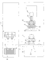
CN101486247A - Cooling and picking device and method for bottle blank - Google Patents

Cooling and picking device and method for bottle blank Download PDF

Info

Publication number
CN101486247A
CN101486247A CNA2008100011782A CN200810001178A CN101486247A CN 101486247 A CN101486247 A CN 101486247A CN A2008100011782 A CNA2008100011782 A CN A2008100011782A CN 200810001178 A CN200810001178 A CN 200810001178A CN 101486247 A CN101486247 A CN 101486247A
Authority
CN
China
Prior art keywords
pinch
acquisition
bottle embryo
cooling
bottle
Prior art date
Legal status (The legal status is an assumption and is not a legal conclusion. Google has not performed a legal analysis and makes no representation as to the accuracy of the status listed.)
Granted
Application number
CNA2008100011782A
Other languages
Chinese (zh)
Other versions
CN101486247B (en
Inventor
陈乐煌
Current Assignee (The listed assignees may be inaccurate. Google has not performed a legal analysis and makes no representation or warranty as to the accuracy of the list.)
Jiejin Automotive Co ltd
Original Assignee
Jiejin Automotive Co ltd
Priority date (The priority date is an assumption and is not a legal conclusion. Google has not performed a legal analysis and makes no representation as to the accuracy of the date listed.)
Filing date
Publication date
Application filed by Jiejin Automotive Co ltd filed Critical Jiejin Automotive Co ltd
Priority to CN2008100011782A priority Critical patent/CN101486247B/en
Publication of CN101486247A publication Critical patent/CN101486247A/en
Application granted granted Critical
Publication of CN101486247B publication Critical patent/CN101486247B/en
Expired - Fee Related legal-status Critical Current
Anticipated expiration legal-status Critical

Links

Images

Landscapes

  • Apparatus Associated With Microorganisms And Enzymes (AREA)

Abstract

A cooling and picking device for bottle blank comprises: a first picking mechanism capable of performing a reciprocating movement for picking each bottle blank molded in a mold of an injection molding machine from the mold; the second picking mechanism also carries out reciprocating movement and is used for picking up the bottle blanks on the first picking mechanism, and the second picking mechanism can sequentially unload the bottle blanks on the second picking mechanism in batches after picking up a preset number of bottle blanks; therefore, the injection molding process and the cooling process of the bottle blanks can be separated, and the time of each bottle blank on the second picking mechanism is controlled, so that each bottle blank can be cooled reliably.

Description

瓶胚的冷却撷取装置及其冷却撷取方法 Cooling pick-up device for preform and cooling pick-up method thereof

技术领域 technical field

本发明涉及一种瓶胚的制造流程,尤指一种瓶胚的冷却撷取装置及其冷却撷取方法。The invention relates to a manufacturing process of a preform, in particular to a preform cooling and picking device and a cooling and picking method thereof.

技术背景 technical background

以往的瓶胚射出成型机,是由一模具在闭模时形成有多数密闭的模穴,并待塑料熔液注入该模穴内,使塑料熔液充满该模穴,且经过一段预定时间的静待降温,使得瓶胚冷凝定型后,模具即会开模并藉一顶出装置将瓶胚予以顶出模穴,即完成整段瓶胚的制造流程。In the past preform injection molding machine, when the mold is closed, a plurality of closed mold cavities are formed, and the plastic melt is injected into the mold cavities, so that the plastic melt fills the mold cavities, and after a predetermined period of static After the temperature is lowered to make the preform condense and shape, the mold will be opened and the preform will be ejected out of the mold cavity by an ejector device, and the entire preform manufacturing process will be completed.

然而上述以往的瓶胚射出成型机,为了让射出的瓶胚冷却定型,以避免由模具脱模时,因瓶胚相互撞击而损及瓶胚外型,所以在制造上,射出后的瓶胚在模具中静待降温时,必须在经过一段凝结成型的时间后,再持续停留一冷却定型时间,而让瓶胚在成型之后能够更进一步的完全定型,如此一来,瓶胚在模具中等待冷却的时间较长,将会相对占用模具下次接续的射出成型时间,因而造成整段射出制程将会停滞,而导致产量降低。However, in the above-mentioned conventional preform injection molding machine, in order to cool and shape the injected preform, so as to avoid damage to the preform shape due to the collision of the preforms when the mold is released from the mold, in manufacturing, the preform after injection When waiting to cool down in the mold, it is necessary to continue to stay for a cooling and setting time after a period of condensing and forming, so that the preform can be further fully shaped after forming. In this way, the preform is waiting in the mold A longer cooling time will relatively occupy the next injection molding time of the mold, thus causing the entire injection process to stagnate, resulting in a decrease in output.

而目前市面上另有一种装设于瓶胚射出成型机旁的冷却装置,如图30所示,其是由移动模1以撷取位于模具2中的各瓶胚3成品后,再将瓶胚3移送至一冷却位置4,而可供冷却装置4进行冷却各瓶胚3的作用,其中,冷却装置4由多个气嘴5构成,如图31所示,当移动模1撷取瓶胚3至冷却位置4时,冷却装置4即会与移动模1相互接合,此时各气嘴5即会伸入各瓶胚3的内部,并进行一喷气冷却的动作。At present, there is another kind of cooling device installed beside the preform injection molding machine on the market, as shown in Figure 30, it uses the mobile mold 1 to pick up the finished products of each preform 3 in the mold 2, and then puts the bottle The preforms 3 are transferred to a cooling position 4, and the cooling device 4 can be used to cool each preform 3, wherein the cooling device 4 is composed of a plurality of air nozzles 5, as shown in Figure 31, when the moving mold 1 picks up the bottle When the preform 3 arrives at the cooling position 4, the cooling device 4 will engage with the movable mold 1, and at this time, each air nozzle 5 will extend into the inside of each preform 3, and perform an air jet cooling action.

然而,此种冷却装置4在与移动模1相互接合,并以各气嘴5对各瓶胚3进行喷气冷却时,由于为使各气嘴5所喷出的空气顺利地流通于各瓶胚3内部,因此,在各瓶胚3与各气嘴5间具有一气流空间6,而当各瓶胚3内部受各气嘴5喷气以进行冷却作用时,由于各气嘴5所喷出的冷却空气将会于各气流空间6中乱窜并导致气旋现象产生,如此一来,将会造成各瓶胚3内部壁缘的冷却效果不平均,从而导致各瓶胚3内部壁缘的变形,并影响各瓶胚3的整体良率;此外,由于此种瓶胚冷却方式,是以喷嘴5伸入于瓶胚3的内部,因此其仅能对瓶胚3的内缘进行冷却动作,并无法使瓶胚3的瓶口获得良好的冷却效果,致使各该瓶胚3于瓶口处极易发生变形现象,而会影响各瓶胚3的瓶口在与瓶盖相互旋接时的气密性,此亦为其缺点之一。However, when this cooling device 4 is connected with the movable mold 1, and each preform 3 is sprayed and cooled with each air nozzle 5, because the air ejected from each air nozzle 5 circulates smoothly in each preform 3 inside, therefore, there is an airflow space 6 between each preform 3 and each air nozzle 5, and when the inside of each preform 3 is cooled by each air nozzle 5 for cooling, due to the air ejected by each air nozzle 5 The cooling air will scurry in each airflow space 6 and cause the cyclone phenomenon to be generated. In this way, the cooling effect of the inner wall edge of each preform 3 will be uneven, resulting in the deformation of the inner wall edge of each preform 3 . And affect the overall yield of each preform 3; in addition, due to this preform cooling method, the nozzle 5 is inserted into the inside of the preform 3, so it can only cool the inner edge of the preform 3, and It is impossible to obtain a good cooling effect on the bottleneck of the preform 3, so that each preform 3 is easily deformed at the bottleneck, which will affect the gas flow of the bottleneck of each preform 3 when it is screwed with the bottle cap. This is also one of its disadvantages.

再者,移动模1于模具2中具有三处不同的撷取位置1A、1B、1C,如图32所示,移动模1先移动至第一撷取位置1A,并将模具2中的各瓶胚3撷取出在模具2外,再与冷却装置4接合以进行冷却动作;而后,移动模1再次进入模具2中并移动至第二撷取位置1B,如图33所示,再将各瓶胚3由模具2中取出以进行冷却动作;之后,移动模1再移动至第三撷取位置1C(如图34所示),以将瓶胚3由模具2中取出以进行冷却动作,当移动模1在进行撷取瓶胚的动作前,会先将移动模1中所欲撷取瓶胚3的撷取位置进行一卸料的动作,并按此步骤持续循环,即可使模具2中所成型的瓶胚3得于模具2外进行冷却动作。Furthermore, the movable mold 1 has three different pick-up positions 1A, 1B, and 1C in the mold 2. As shown in FIG. The preform 3 is picked out of the mold 2, and then engaged with the cooling device 4 for cooling; then, the movable mold 1 enters the mold 2 again and moves to the second pick-up position 1B, as shown in FIG. 33 , and each The preform 3 is taken out from the mold 2 for cooling; after that, the movable mold 1 moves to the third pick-up position 1C (as shown in FIG. 34 ) to take the preform 3 out of the mold 2 for cooling. Before the moving mold 1 performs the action of picking up the preform, it will first perform an unloading action on the picking position of the preform 3 to be picked up in the moving mold 1, and continue to cycle according to this step, and the mold can be made The preform 3 molded in 2 must be cooled outside the mold 2.

然而,以此种撷取方式所设计的移动模1与冷却装置4其体积都会相当庞大,而非常耗占厂房空间;且当移动模1于模具2中进行撷取动作时,由于移动模1中还会承载有前一次所撷取而尚未卸除的瓶胚3,因此,整个移动模1的载重极高,如此将造成移动模1于进行撷取移动时的速度相当缓慢,而严重影响到撷取各瓶胚3时的效率。However, the volume of the movable mold 1 and the cooling device 4 designed in this way of extraction will be quite large, and consume a lot of workshop space; There will also be preforms 3 that have been retrieved and not yet unloaded, so the load of the entire mobile mold 1 is very high, which will cause the speed of the mobile mold 1 to be very slow when picking up and moving, which will seriously affect to the efficiency when each preform 3 is retrieved.

发明内容 Contents of the invention

本发明的目的在于提供一种瓶胚的冷却撷取装置及其冷却撷取方法,其可将瓶胚射出成型的流程与瓶胚冷却流程分开进行,以使射出成型机可持续进行射出成型的操作,而不被中断,由此可有效提升瓶胚的生产效率。The object of the present invention is to provide a preform cooling pick-up device and cooling pick-up method thereof, which can separate the preform injection molding process from the preform cooling process, so that the injection molding machine can continue to perform injection molding Operation without being interrupted, which can effectively improve the production efficiency of preforms.

本发明的另一目的在于提供一种瓶胚的冷却撷取装置及其冷却撷取方法,其由第一夹制部在撷取瓶胚时,即进行第一阶段于各瓶胚外缘进行冷却的动作;而当第二夹制部与第一夹制部上的各瓶胚相互接合时,各瓶胚即会同时受到第一夹制部与第二夹制部分别对瓶胚之外、内缘进行冷却,并藉此提供瓶胚第二阶段的冷却动作;而后,再由该第二夹制部将瓶胚载运至集料位置,并持续对瓶胚内缘进行第三阶段的冷却,使本发明藉由可提供各瓶胚进行多阶段的冷却动作,以使瓶胚确实获得冷却,进而使各瓶胚的良率得以有效提升。Another object of the present invention is to provide a preform cooling pick-up device and its cooling pick-up method. When the first clamping part picks up the preforms, the first stage is carried out on the outer edge of each preform. Cooling action; and when the preforms on the second clamping part and the first clamping part are joined together, each preform will be subjected to the first clamping part and the second clamping part respectively. , the inner edge of the preform is cooled, and thereby provides the second stage of cooling action for the preform; then, the second clamping part carries the preform to the collecting position, and continues to perform the third stage of cooling on the inner edge of the preform Cooling, the present invention can provide each preform to perform multi-stage cooling action, so that the preforms can be cooled reliably, and then the yield rate of each preform can be effectively improved.

本发明的又一目的,在于提供一种瓶胚的冷却撷取装置及其冷却撷取方法,由三个阶段依序分批卸除由第二撷取机构的第二夹制部所完成冷却动作的各瓶胚,而得以延长尚未卸除的其余各瓶胚的冷却时间,以使冷却效果更加完善。Another object of the present invention is to provide a preform cooling pick-up device and its cooling pick-up method, in which the cooling completed by the second clamping part of the second pick-up mechanism is removed in batches in three stages. The preforms that are moving can prolong the cooling time of the remaining preforms that have not been removed, so that the cooling effect can be more perfect.

本发明的再一目的,在于提供一种瓶胚的冷却撷取装置及其冷却撷取方法,因第二撷取机构上的各冷却管的外缘是恰与其所撷取的各瓶胚的内缘相互贴合,因此使各瓶胚得以更贴近冷却源以达迅速冷却的功效,且藉由各瓶胚的内缘贴合于该冷却管上,因此又可提供各该瓶胚的瓶口一顶撑的作用,而避免各瓶胚的瓶口因遇冷收缩产生变形,确保瓶口的真圆度,使得瓶盖与瓶胚的瓶口相互接合时,可获得良好的气密性。Another object of the present invention is to provide a preform cooling pick-up device and its cooling pick-up method, because the outer edges of the cooling tubes on the second pick-up mechanism are just in line with the pick-up preforms. The inner edges of each preform are attached to each other, so that each preform can be closer to the cooling source to achieve the effect of rapid cooling, and the inner edge of each preform is attached to the cooling tube, so that the preforms can be provided. Mouth-supporting function, to avoid the deformation of the bottle mouth of each preform due to cold shrinkage, to ensure the roundness of the bottle mouth, so that when the bottle cap and the bottle mouth of the preform are joined together, good airtightness can be obtained .

本发明的又一目的,在于提供一种瓶胚的冷却撷取装置及其冷却撷取方法,由于第一撷取机构将模具中的瓶胚予以取出,再转交至第二撷取机构上予以集中冷却,藉此该第一撷取机构的体积即可有效减少,并大幅减少其载重量而使本发明的第一撷取机构得以进行高速移动,并使各瓶胚取出的速度可以更快,进而提升整体制程的效率。Yet another object of the present invention is to provide a preform cooling pick-up device and cooling pick-up method thereof, since the first pick-up mechanism takes out the preform from the mold, and then transfers it to the second pick-up mechanism for further processing. Concentrated cooling, so that the volume of the first picking mechanism can be effectively reduced, and its load capacity can be greatly reduced so that the first picking mechanism of the present invention can move at high speed, and the speed of taking out each preform can be faster , thereby improving the efficiency of the overall process.

本发明的再一目的,在于提供一种瓶胚的冷却撷取装置及其冷却撷取方法,藉由可大幅降低第一撷取机构的载重量,而可使驱动该第一撷取机构的动力源亦可随之降低,由此达到节省能源以及降低成本的功效。Another object of the present invention is to provide a preform cooling pick-up device and cooling pick-up method thereof, which can greatly reduce the load capacity of the first pick-up mechanism, and make the driving of the first pick-up mechanism The power source can also be reduced accordingly, thereby achieving the effects of energy saving and cost reduction.

为达前述之目的,本发明提供一种瓶胚的冷却撷取装置,其设置于一射出成型机的一侧,而用以撷取由该射出成型机的模具所成型的瓶胚,该瓶胚的冷却撷取装置包含有:In order to achieve the aforementioned purpose, the present invention provides a preform cooling pick-up device, which is arranged on one side of an injection molding machine, and is used to pick up the preform formed by the mold of the injection molding machine, the bottle Embryo cooling extraction device includes:

一第一撷取机构,其具有第一传动臂以及第一夹制部,该传动臂可进行往复移动,而第一夹制部设置于该传动臂的一端,而同步随第一传动臂进行移动,且第一撷取机构利用第一夹制部将射出成型机的模具所成型的各瓶胚由模具中撷取出来,第一夹制部对瓶胚外缘进行第一阶段的冷却作用,而射出成型机在各瓶胚被取出后,将再次进行射出成型瓶胚的动作,以供第一撷取机构的下一次撷取动作;A first pick-up mechanism, which has a first transmission arm and a first clamping part, the transmission arm can move back and forth, and the first clamping part is arranged at one end of the transmission arm, and is synchronized with the first transmission arm Move, and the first picking mechanism uses the first clamping part to pick up each preform formed by the mold of the injection molding machine from the mold, and the first clamping part performs the first-stage cooling effect on the outer edge of the preform , and after each preform is taken out, the injection molding machine will perform the action of injecting and molding the preform again for the next picking action of the first picking mechanism;

一第二撷取机构,其具有第二传动臂以及第二夹制部,第二传动臂可进行一往复移动,且第二夹制部设置于该第二传动臂的一端,并同步随第二传动臂进行移动,而第二撷取机构以第二夹制部撷取第一撷取机构的第一夹制部上的各瓶胚,且于撷取中使第一撷取机构的第一夹制部与第二撷取机构的第二夹制部同时对各瓶胚之外、内缘进行第二阶段的冷却作用,而于撷取后持续对各瓶胚的内缘进行第三阶段的冷却作用,且该第二夹制部于撷取至一预定数量的瓶胚后,即会将位于该第二夹制部上的各瓶胚依序予以分批卸除。A second pick-up mechanism, which has a second transmission arm and a second clamping part, the second transmission arm can perform a reciprocating movement, and the second clamping part is arranged at one end of the second transmission arm, and synchronizes with the second clamping part The two transmission arms move, and the second pick-up mechanism picks up each preform on the first clamping part of the first pick-up mechanism with the second clamping part, and makes the first pick-up mechanism of the first pick-up mechanism during pick-up The first clamping part and the second clamping part of the second pick-up mechanism perform the second-stage cooling on the outer and inner edges of each preform at the same time, and continue to perform the third cooling on the inner edge of each preform after picking. staged cooling, and after the second clamping part picks up a predetermined number of preforms, the preforms located on the second clamping part will be sequentially removed in batches.

本发明具有以下优点:The present invention has the following advantages:

一、本发明将瓶胚由模具中取出以进行冷却程序,藉此将瓶胚射出成型的流程与瓶胚冷却流程分开进行,以使该射出成型机得以持续进行射出成型的动作,而不被中断,由此可提高该射出成型机的生产效率。1. In the present invention, the preform is taken out from the mold to perform the cooling process, thereby separating the preform injection molding process from the preform cooling process, so that the injection molding machine can continue to perform the injection molding action without being blocked interruption, thereby improving the production efficiency of the injection molding machine.

二、本发明的冷却撷取装置,由于第一夹制部在撷取瓶胚时,即进行第一阶段于各瓶胚外缘进行冷却的动作;而当第二夹制部与第一夹制部上的各瓶胚相互接合时,各瓶胚即会同时受到第一夹制部与第二夹制部分别对瓶胚的外、内缘进行冷却,并提供瓶胚第二阶段的冷却动作;而后,再由第二夹制部将瓶胚载运至集料位置,并持续对瓶胚内缘进行第三阶段的冷却,使本发明可提供各瓶胚进行多阶段的冷却动作,以使瓶胚确实获得冷却,进而可以有效提升各瓶胚的良率。2. In the cooling pick-up device of the present invention, when the first clamping part picks up the preforms, it performs the cooling action at the outer edge of each preform in the first stage; and when the second clamping part and the first clamping part When the preforms on the manufacturing part are joined to each other, each preform will be simultaneously cooled by the first clamping part and the second clamping part to cool the outer and inner edges of the preforms respectively, and provide the second stage of cooling for the preforms Then, the preforms are carried to the collecting position by the second clamping part, and the inner edge of the preforms is continuously cooled in the third stage, so that the present invention can provide multi-stage cooling actions for each preform, so as to The preforms are indeed cooled, which can effectively improve the yield of each preform.

三、本发明通过三个阶段依序分批卸除由第二撷取机构的第二夹制部所完成冷却动作的各瓶胚,而得以延长尚未卸除的其余各瓶胚的冷却时间,使冷却效果更加完善。3. The present invention sequentially removes the preforms that have been cooled by the second clamping part of the second picking mechanism in batches in three stages, thereby prolonging the cooling time of the remaining preforms that have not been removed. Make the cooling effect more perfect.

四、本发明由于其第二撷取机构上的各冷却管的外缘是与其所撷取的各瓶胚的内缘相互贴合,因此可使各瓶胚得以更贴近冷却源以达迅速冷却的功效,且由于各瓶胚的内缘是贴合于该冷却管上,因此可提供给各瓶胚的瓶口一顶撑作用,避免各瓶胚的瓶口因遇冷收缩而产生变形,以确保瓶口的真圆度,使得瓶盖与瓶胚的瓶口相互接合时,可获得良好的气密性。4. In the present invention, since the outer edges of the cooling pipes on the second picking mechanism are in close contact with the inner edges of the preforms it picks up, each preform can be brought closer to the cooling source to achieve rapid cooling The effect, and because the inner edge of each preform is attached to the cooling tube, it can provide a support function for the bottle mouth of each preform, avoiding the deformation of the bottle mouth of each preform due to cold shrinkage, To ensure the true roundness of the bottle mouth, good airtightness can be obtained when the bottle cap and the bottle mouth of the preform are joined together.

五、本发明利用第一撷取机构将模具中的瓶胚予以取出,再转交至第二撷取机构上予以集中冷却,藉此第一撷取机构的体积即可有效减少,并大幅减少其载重量而使本发明的第一撷取机构得进行高速移动,并使各瓶胚取出的速度更快,进而提升整体制程的效率。5. The present invention uses the first picking mechanism to take out the preforms in the mold, and then transfers them to the second picking mechanism for centralized cooling, so that the volume of the first picking mechanism can be effectively reduced, and its The load capacity enables the first picking mechanism of the present invention to move at a high speed, and makes each preform take out faster, thereby improving the efficiency of the overall process.

六、本发明由于可大幅降低第一撷取机构的载重量,而使驱动第一撷取机构的动力源亦可随之降低,并藉此达到节省能源以及降低成本的功效。6. Since the present invention can greatly reduce the load capacity of the first picking mechanism, the power source for driving the first picking mechanism can also be reduced accordingly, thereby saving energy and reducing costs.

附图说明 Description of drawings

图1是本发明的俯视图Fig. 1 is a top view of the present invention

图2是本发明的主视图Fig. 2 is the front view of the present invention

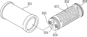
图3是本发明的瓶胚吸引管的立体分解图Fig. 3 is a three-dimensional exploded view of the preform suction tube of the present invention

图4是本发明的第一夹制部的结构示意图Fig. 4 is a schematic structural view of the first clamping part of the present invention

图5是本发明的第二夹制部的结构示意图Fig. 5 is a schematic structural view of the second clamping part of the present invention

图6是本发明的第一夹制部与第二夹制部相互接合时的结构状态示意图Fig. 6 is a schematic diagram of the structural state when the first clamping part and the second clamping part of the present invention are engaged with each other

图7至图29是本发明的瓶胚冷却撷取方法的流程示意图7 to 29 are schematic flow charts of the preform cooling and extraction method of the present invention

图30是以往的瓶胚冷却装置的示意图Figure 30 is a schematic diagram of a conventional preform cooling device

图31是以往的瓶胚冷却装置于进行冷却动作时的局部放大示意图Fig. 31 is a partially enlarged schematic view of a conventional preform cooling device during cooling operation

图32是以往的瓶胚冷却装置于撷取瓶胚时的动作示意图,其用以显示该夹臂位于第一撷取位置而准备撷取瓶胚时的状态Fig. 32 is a schematic diagram of the action of the conventional preform cooling device when picking up the preform, which is used to show the state when the clamp arm is in the first picking position and ready to pick up the preform

图33是以往瓶胚冷却装置在撷取瓶胚时的动作示意图,其用以显示该夹臂位于第二撷取位置,而准备撷取瓶胚时的状态Figure 33 is a schematic diagram of the action of the conventional preform cooling device when picking up the preform, which is used to show the state when the clamp arm is in the second picking position and ready to pick up the preform

图34是以往的瓶胚冷却装置在撷取瓶胚时的动作示意图,其用以显示该夹臂位于第三撷取位置,而准备撷取瓶胚时的状态Fig. 34 is a schematic diagram of the action of the conventional preform cooling device when picking up the preform, which is used to show the state when the clamp arm is in the third picking position and ready to pick up the preform

本发明的上述目的通过具体实施例进行详细说明,但不以此为对本发明保护范围的限制。The above purpose of the present invention is described in detail through specific examples, but it is not intended to limit the protection scope of the present invention.

具体实施方式 Detailed ways

如图1至图29所示,图中揭示的均为本发明所选用的实施例。As shown in Fig. 1 to Fig. 29, all those disclosed in the figures are selected embodiments of the present invention.

如图1、图2所示,其为本发明所提供的一种瓶胚的冷却撷取装置,其装设于一射出成型机11的一侧,射出成型机11具有一可反复闭模及开模的模具12,模具12于闭模时形成有多个的密闭模穴14,以供塑料熔液注入于模穴14中并经一成型时间之后,即能形成多个瓶胚21,并待该模具12于开模后可供本发明的冷却撷取装置取出;而该冷却撷取装置主要由一第一撷取机构31以及一第二撷取机构41所组成,其中:该第一撷取机构31,其系具有一轨道32、一第一传动臂33以及一第一夹制部34,第一传动臂33可沿该轨道32而于一起始位置A、一目标位置B以及一冷却位置C间进行往复移动,其中,目标位置B位于模具12中,该冷却位置C位于与第二撷取机构41相对应的一侧,起始位置A则位于该目标位置B以及冷却位置C之间,本实施例中,起始位置A邻近于该模具12一侧,而当模具12尚未完成射出成型时,第一夹制部34位于起始位置A以等待模具12开模,第一夹制部34设于该第一传动臂33的一端,而可同步随第一传动臂33进行移动。As shown in Fig. 1 and Fig. 2, it is a cooling pick-up device for a preform provided by the present invention, which is installed on one side of an injection molding machine 11, and the injection molding machine 11 has a mold that can be closed repeatedly and The mold 12 of the mold opening, the mold 12 forms a plurality of airtight mold cavities 14 when the mold is closed, for injection of plastic melt into the mold cavities 14 and after a molding time, a plurality of preforms 21 can be formed, and After the mold 12 is opened, it can be taken out by the cooling pick-up device of the present invention; and the cooling pick-up device is mainly composed of a first pick-up mechanism 31 and a second pick-up mechanism 41, wherein: the first pick-up mechanism The pick-up mechanism 31 has a track 32, a first transmission arm 33 and a first clamping portion 34, and the first transmission arm 33 can move along the track 32 at an initial position A, a target position B and a reciprocating movement between the cooling positions C, wherein the target position B is located in the mold 12, the cooling position C is located on the side corresponding to the second pick-up mechanism 41, and the starting position A is located at the target position B and the cooling position C Between, in this embodiment, the initial position A is adjacent to the side of the mold 12, and when the mold 12 has not yet completed the injection molding, the first clamping part 34 is located at the initial position A to wait for the mold 12 to open, the first The clamping part 34 is disposed at one end of the first transmission arm 33 and can move synchronously with the first transmission arm 33 .

如图3、图4所示,其中第一夹制部34上设有多个瓶胚吸引管35,第一夹制部34中具有一第一通槽36与一第二通槽37,第一通槽36与一第一气嘴38相接而进行一吸取空气的动作,第二通槽37可供一冷却液流通,且各瓶胚吸引管35分别由一外套件351与一内置件352相互套接而成,而于内置件352一端具有一开口353仅供容置瓶胚21,另一端则开设有一气孔354、一进水孔355及一出水口356,该气孔354以其一端与第一通槽36相连通,而该气孔354另一端则与内置件352的开口353相连通,并于该内置件352的外缘环设有一螺旋状缺槽357,该进水口355与该出水口356分别以其一端与第二通槽37相连通,而该进水口355与该出水口356的另一端则分别与该螺旋状缺槽357相连通,使得第二通槽37所流通的冷却液得以沿进水口355进入于内置件352外缘的螺旋状缺槽357,再由出水口356流出;当射出成型机11的模具12开模时,该第一传动臂33即带动第一夹制部34由起始位置A移动至该目标位置B(如图1所示),并以各瓶胚吸引管35的开口353嵌套瓶胚21,此时藉由第一气嘴38吸气所造成的负压真空作用,而使瓶胚21紧密的被吸附于各瓶胚吸引管35的开口353中,并于此同时,藉由瓶胚吸引管35中的螺旋状缺槽357所流通的冷却液的冷却作用,而使瓶胚21分别被吸附于各瓶胚吸引管35的开口353中时,即可对瓶胚21的外缘进行第一阶段的冷却作用,而后第一夹制部34再携带瓶胚21移动至该冷却位置C,且该冷却位置C分为一第一撷取位置C1、一第二撷取位置C2以及一第三撷取位置C3,(在后面的附图中标出C1、C2、C3的位置)而该射出成型机11在模具12各瓶胚21被取出后,将再次进行射出成型瓶胚21的动作,以供第一撷取机构31的第一夹制部34进行下一次的撷取动作。As shown in Fig. 3 and Fig. 4, a plurality of preform suction tubes 35 are arranged on the first clamping part 34, a first through groove 36 and a second through groove 37 are arranged in the first clamping part 34, A through groove 36 is connected with a first air nozzle 38 to perform an action of sucking air, the second through groove 37 can allow a coolant to circulate, and each preform suction pipe 35 is composed of an outer sleeve 351 and an inner part respectively. 352 are nested with each other, and one end of the built-in part 352 has an opening 353 only for accommodating the preform 21, and the other end is provided with an air hole 354, a water inlet 355 and a water outlet 356. It communicates with the first through groove 36, and the other end of the air hole 354 communicates with the opening 353 of the built-in part 352, and a spiral slot 357 is arranged on the outer edge ring of the built-in part 352, the water inlet 355 and the The water outlet 356 communicates with the second through groove 37 with its one end respectively, and the other end of the water inlet 355 and the water outlet 356 communicates with the helical slot 357 respectively, so that the flow of the second through groove 37 The coolant can enter the spiral groove 357 on the outer edge of the built-in part 352 along the water inlet 355, and then flow out from the water outlet 356; when the mold 12 of the injection molding machine 11 is opened, the first transmission arm 33 drives the first The clamping part 34 moves from the starting position A to the target position B (as shown in FIG. 1 ), and nests the preforms 21 with the openings 353 of the preform suction pipes 35. At this time, the first air nozzle 38 sucks The negative pressure and vacuum effect caused by the gas makes the preforms 21 tightly adsorbed in the openings 353 of the preform suction pipes 35, and at the same time, the preforms 21 are absorbed by the spiral grooves 357 in the preform suction pipes 35. The cooling effect of the circulating cooling liquid, so that when the preforms 21 are respectively adsorbed in the openings 353 of the suction pipes 35 of the preforms, the outer edge of the preforms 21 can be cooled in the first stage, and then the first clamping The manufacturing part 34 carries the preform 21 and moves to the cooling position C, and the cooling position C is divided into a first picking position C1, a second picking position C2 and a third picking position C3, (in the following The positions of C1, C2, and C3 are marked in the accompanying drawings), and the injection molding machine 11 will carry out the action of injection molding the preforms 21 again after the preforms 21 of the mold 12 are taken out for the first pick-up mechanism 31. A clamping part 34 performs the next picking action.

如图1及图2所示,其中,第二撷取机构41具有一第二传动臂42以及一第二夹制部43,第二传动臂42可在集料位置D与取料位置E之间进行往复移动,第二夹制部43设于第二传动臂42的一端,而可同步随第二传动臂42进行移动。如图5所示,其中,第二夹制部43上设有多根的冷却管45,而第二夹制部43具有一第三通槽46与一第四通槽47,第三通槽46用与第二气嘴48相接而进行吸取空气的动作,第四通槽47则可供一冷却液流通。此外,第二夹制部43枢接于第二传动臂42的一端,以使第二夹制部43于集料位置D与卸料位置F间进行往复旋转移动(如图18所示)。As shown in Figure 1 and Figure 2, wherein, the second pick-up mechanism 41 has a second transmission arm 42 and a second clamping part 43, the second transmission arm 42 can be between the collecting position D and the material taking position E The second clamping part 43 is disposed at one end of the second transmission arm 42 and can move synchronously with the second transmission arm 42 . As shown in Figure 5, wherein, the second clamping part 43 is provided with a plurality of cooling pipes 45, and the second clamping part 43 has a third through groove 46 and a fourth through groove 47, the third through groove 46 is used to connect with the second air nozzle 48 to carry out the action of sucking air, and the fourth through groove 47 is then available for a coolant to circulate. In addition, the second clamping part 43 is pivotally connected to one end of the second transmission arm 42 so that the second clamping part 43 can reciprocate and rotate between the collecting position D and the discharging position F (as shown in FIG. 18 ).

此外,冷却管45于其轴心分别设有一贯通的通孔451,且该通孔451并与该第三通槽46相连通,并于冷却管45内部具有一冷却流道452,且冷却流道452与第四通槽47相互连通,而使流通于第四通槽47冷却液亦得以流通至冷却管45的冷却流道452中,且冷却管45的外缘形状恰与瓶胚21的内缘形状相互对应;而当第一夹制部34携带瓶胚21至第一传动臂33的冷却位置C的第一撷取位置C1时,第二传动臂42即同时由该集料位置D移动至该取料位置E,并以第二传动臂42上的冷却管45而与第一夹制部34上的瓶胚21相互接合,此时,如图6所示,各瓶胚21同时受到该第一夹制部34与该第二夹制部43分别对该瓶胚21之外、内缘进行第二阶段的冷却动作,且由于该冷却管45的外缘恰与其所撷取的瓶胚21的内缘相互贴合,藉此,除了可将各该瓶胚21上的热度迅速冷却之外,更可使各瓶胚21因遇冷而产生收缩现象时,使各瓶胚21的内缘更贴近该冷却管45所产生的冷却源,以得到更好的冷却效果,且经过一预定的冷却时间后,第一撷取机构31的第一气嘴38将停止吸气作用,而改由第二撷取机构41的第二气嘴48进行吸气,并藉以形成一负压真空作用,使各瓶胚21得改由被第二夹制部43的各冷却管45紧密的吸附,此时,第二传动臂42即再由该取料位置E复归至集料位置D中,并由各冷却管45内部的冷却流道452所流通的冷却液的冷却作用,而持续对瓶胚21内缘进行第三阶段的冷却作用,并于此时第一夹制部34退回该起始位置A,以等待射出成型机11完成下一段的瓶胚21射出成型,再以第一撷取机构31的第一夹制部34继续对已完成射出成型的瓶胚21进行撷取的动作,而后第一夹制部34将所撷取出的瓶胚21依序载运至第二撷取位置C2及第三撷取位置C3,以供第二撷取机构41进行撷取。In addition, the cooling pipe 45 is respectively provided with a through hole 451 in its axial center, and the through hole 451 communicates with the third through groove 46, and has a cooling channel 452 inside the cooling pipe 45, and the cooling flow The channel 452 communicates with the fourth through-groove 47, so that the cooling fluid flowing through the fourth through-groove 47 can also flow into the cooling channel 452 of the cooling pipe 45, and the shape of the outer edge of the cooling pipe 45 is exactly the same as that of the preform 21. The shapes of the inner edges correspond to each other; and when the first clamping part 34 carries the preform 21 to the first pick-up position C1 of the cooling position C of the first transmission arm 33, the second transmission arm 42 simultaneously moves from the collecting position D Move to the pick-up position E, and use the cooling pipe 45 on the second transmission arm 42 to engage with the preforms 21 on the first clamping part 34. At this time, as shown in FIG. 6, each preform 21 simultaneously The outer and inner edges of the preform 21 are cooled by the first clamping part 34 and the second clamping part 43 respectively, and because the outer edge of the cooling pipe 45 is exactly the same as the captured The inner edges of the preforms 21 are attached to each other, thereby, in addition to rapidly cooling the heat on each preform 21, it is also possible to make each preform 21 shrink when it is cold. The inner edge of the inner edge is closer to the cooling source generated by the cooling pipe 45 to obtain a better cooling effect, and after a predetermined cooling time, the first air nozzle 38 of the first extraction mechanism 31 will stop the suction function, Instead, the second air nozzle 48 of the second pick-up mechanism 41 is used to inhale air, thereby forming a negative pressure vacuum effect, so that each preform 21 must be tightly closed by the cooling pipes 45 of the second clamping part 43 instead. Adsorption, at this time, the second transmission arm 42 returns to the collection position D from the material taking position E, and is cooled by the cooling liquid circulated in the cooling channels 452 inside the cooling pipes 45, and continues to The inner edge of the preform 21 undergoes the third stage of cooling, and at this time the first clamping part 34 returns to the starting position A, waiting for the injection molding machine 11 to complete the injection molding of the next stage of the preform 21, and then the first The first clamping part 34 of the picking mechanism 31 continues to pick up the injection-molded preforms 21, and then the first clamping part 34 carries the picked out preforms 21 to the second picker in sequence. The position C2 and the third capturing position C3 are used for capturing by the second capturing mechanism 41 .

然而,当第二撷取机构41的第二夹制部43经上述撷取动作依序撷取至一定数量的瓶胚21后,第二夹制部43即会由一回转气缸44的作用,而由集料位置D旋动至卸料位置F,此时第二气嘴48将停止吸气动作,并由一顶推件49的顶推作用,而将第二夹制部43上对应第一夹制部34的冷却位置C,由第一撷取位置C1所撷取已完成冷却的瓶胚21开始依序予以分批卸出,而于此特别提出说明的是,其中,由第一气嘴38与第二气嘴48所构成的负压真空回路设计为习知结构,故于此不再详述其构造。However, when the second clamping part 43 of the second picking mechanism 41 picks up a certain number of preforms 21 sequentially through the above picking action, the second clamping part 43 will be activated by a rotary cylinder 44, And rotate from the collecting position D to the discharging position F, at this time the second air nozzle 48 will stop the air suction action, and by the pushing action of a push piece 49, the second clamping part 43 corresponding to the first In the cooling position C of a clamping part 34, the preforms 21 that have been picked up and cooled by the first pick-up position C1 are sequentially unloaded in batches. The negative pressure vacuum circuit formed by the gas nozzle 38 and the second gas nozzle 48 is designed as a conventional structure, so its structure will not be described in detail here.

一输送机构51,其设置于第二撷取机构41下方,输送机构51于本实施例中为一输送带结构,仅供承接由第二撷取机构41的第二夹制部43所卸除的已完成冷却的各瓶胚21,并将瓶胚21予以输送至下一制程。A conveying mechanism 51, which is arranged below the second picking mechanism 41, the conveying mechanism 51 is a conveyor belt structure in this embodiment, and is only used for accepting the unloading by the second clamping part 43 of the second picking mechanism 41. Each preform 21 that has been cooled, and the preform 21 is transported to the next process.

而为提高瓶胚21的冷却速度,亦可于第二撷取机构41旁装设有一除雾机(图中未示),该除雾机可用以吹出一冷空气61(如第5图),而可加速于第二撷取机构41的第二夹制部43上各瓶胚21的冷却速度,由于除雾机为习知结构,且并非本发明的申请重点,故于此容不在详述其整体结构。In order to improve the cooling rate of the preform 21, a defogger (not shown) can also be installed next to the second pick-up mechanism 41, and the defogger can be used to blow out a cold air 61 (as shown in Figure 5). , and can accelerate the cooling rate of each preform 21 on the second clamping part 43 of the second pick-up mechanism 41. Since the defogger is a conventional structure and is not the focus of the application of the present invention, it will not be described in detail here. describe its overall structure.

如图7至图29,其为本发明利用上述构件所进行的冷却撷取方法,其步骤包含有:As shown in Fig. 7 to Fig. 29, it is the cooling extraction method performed by the above-mentioned components in the present invention, and its steps include:

a.射出成型机11的模具12进行闭模,并于各模穴14中进行各瓶胚21的射出成型作业(如图7所示);a. The mold 12 of the injection molding machine 11 is closed, and the injection molding operation of each preform 21 is carried out in each mold cavity 14 (as shown in Figure 7);

b.经一预定成型时间后,射出成型机11进行开模,并形成有多个高温瓶胚21成品(如图8所示);b. After a predetermined molding time, the injection molding machine 11 opens the mold, and forms a plurality of high-temperature preforms 21 finished products (as shown in FIG. 8 );

c.第一撷取机构31的第一夹制部34,由起始位置A移动至目标位置B(如图9所示),而进入呈开模状态的模具12中,此时,模具12内的顶推模16将瓶胚21往第一夹制部34的方向顶出,而使瓶胚21恰可容置在第一夹制部34的各瓶胚吸引管35中,并由第一夹制部34内部的第一气嘴38所产生的吸气负压作用,而将瓶胚21撷取至第一夹制部34上(如图10所示);c. The first clamping part 34 of the first picking mechanism 31 moves from the initial position A to the target position B (as shown in Figure 9 ), and enters the mold 12 in the mold-opening state. At this time, the mold 12 The inner pushing mold 16 pushes the preform 21 out toward the direction of the first clamping part 34, so that the preform 21 can be accommodated in each preform suction tube 35 of the first clamping part 34, and the The suction negative pressure generated by the first air nozzle 38 inside a clamping part 34 captures the preform 21 onto the first clamping part 34 (as shown in FIG. 10 );

d.第一撷取机构31的第一夹制部34,由目标位置B移动至该冷却位置C的第一撷取位置C1,而使各瓶胚21得移出于该模具12外,且第一该撷取机构31的第一夹制部34由于其内部流通的冷却液作用,而可对瓶胚21的外缘进行第一阶段的冷却作用,且第一撷取机构31将瓶胚21移出模具12后,射出成型机11随即闭模以进行下一段的射出成型加工(如图11及图12所示);d. The first clamping part 34 of the first picking mechanism 31 moves from the target position B to the first picking position C1 of the cooling position C, so that each preform 21 has to be moved out of the mold 12, and the second The first clamping portion 34 of the pick-up mechanism 31 can perform a first-stage cooling effect on the outer edge of the preform 21 due to the cooling liquid flowing inside it, and the first pick-up mechanism 31 will hold the preform 21 After removing the mold 12, the injection molding machine 11 closes the mold immediately to carry out the next stage of injection molding processing (as shown in Figure 11 and Figure 12);

e.第二撷取机构41的第二夹制部43,由集料位置D移动至取料位置E,而与第一夹制部34上的各瓶胚21相互接合,此时,各瓶胚21同时受到第一夹制部34与第二夹制部43分别对瓶胚的外、内缘进行第二阶段的冷却动作(如图13所示),并经一预定的冷却时间后,再由第二夹制部43将瓶胚21由取料位置E载运至集料位置D上(如图14所示),并于此同时,第二撷取机构41的第二夹制部43持续对各瓶胚21内缘进行第三阶段的冷却动作,且第一夹制部34由第一撷取位置C1复归至起始位置A,以待该射出成型机11完成下一段的瓶胚21射出成型,再以第一撷取机构31的第一夹制部34继续对已完成成型的各瓶胚21进行撷取动作(如图15所示);e. The second clamping part 43 of the second pick-up mechanism 41 moves from the collecting position D to the taking-out position E, and engages with each preform 21 on the first clamping part 34. At this time, each bottle The preform 21 is simultaneously subjected to the second-stage cooling action of the outer and inner edges of the preform by the first clamping part 34 and the second clamping part 43 (as shown in FIG. 13 ), and after a predetermined cooling time, Then the preform 21 is carried by the second clamping part 43 from the retrieving position E to the collecting position D (as shown in Figure 14), and at the same time, the second clamping part 43 of the second pick-up mechanism 41 Continue to carry out the third-stage cooling action on the inner edge of each preform 21, and the first clamping part 34 returns from the first picking position C1 to the initial position A, waiting for the injection molding machine 11 to complete the next stage of the preform 21 injection molding, and then use the first clamping part 34 of the first picking mechanism 31 to continue picking up each preform 21 that has been formed (as shown in Figure 15);

f.重复步骤b~步骤e,其中,并令第一夹制部34将瓶胚21载运至第二撷取位置C2,再以第二夹制部43撷取各瓶胚21(如图16所示),之后第一夹制部34再由模具12中将各瓶胚21载运至第三撷取位置C3,以供第二夹制部43撷取,而使第二夹制部43上撷取至一预定数量的瓶胚21(如图17所示);f. Steps b to e are repeated, wherein the first clamping part 34 is used to carry the preforms 21 to the second picking position C2, and then the second clamping part 43 is used to pick up each preform 21 (as shown in Figure 16 shown), and then the first clamping part 34 carries each preform 21 from the mold 12 to the third pick-up position C3 for the second clamping part 43 to pick up, so that the second clamping part 43 Capture a predetermined number of preforms 21 (as shown in Figure 17);

g.第二撷取机构41的第二夹制部43由一旋转汽缸44的作用,而由集料位置D移动至卸料位置F以进行一卸料动作(如图18所示),接着并将一部份的瓶胚21由第二夹制部43卸除;(以本实施例为例,是先将第一排冷却管与第四排冷却管上的瓶胚21予以卸除,如图19所示);g. The second clamping part 43 of the second picking mechanism 41 is moved from the collecting position D to the discharging position F by the action of a rotating cylinder 44 to perform a discharging action (as shown in FIG. 18 ), and then And a part of the preforms 21 are removed from the second clamping section 43; (taking this embodiment as an example, the preforms 21 on the first row of cooling pipes and the fourth row of cooling pipes are first removed, as shown in Figure 19);

h.以一输出机构51承接由第二夹制部43所卸出已完成冷却的瓶胚21,并将瓶胚21予以输出(如图19所示);h. Use an output mechanism 51 to accept the cooled preform 21 discharged from the second clamping part 43, and output the preform 21 (as shown in Figure 19);

i.继续重复步骤b~步骤e,其中,第一夹制部34再次移动至第一撷取位置C1,且第二夹制部43以步骤g所卸除瓶胚21的部分撷取第一夹制部34上的瓶胚21(以本实施例为例,当第一夹制部34移动至第一撷取位置C1时,该第一夹制部34上的瓶胚21与第二夹制部43的第一排冷却管与第四排冷却管相互对应,并藉以撷取位于第一夹制部34上的瓶胚21,如图20及图21所示);i. Continue to repeat step b to step e, wherein the first clamping part 34 moves to the first picking position C1 again, and the second clamping part 43 picks up the part of the preform 21 removed in step g for the first The preform 21 on the clamping part 34 (taking this embodiment as an example, when the first clamping part 34 moves to the first picking position C1, the preform 21 on the first clamping part 34 and the second clamping part The first row of cooling pipes and the fourth row of cooling pipes of the manufacturing part 43 correspond to each other, and are used to pick up the preform 21 located on the first clamping part 34, as shown in Figure 20 and Figure 21);

j.第二撷取机构41的第二夹制部43由集料位置D移动至卸料位置F而进行一卸料动作,以将另一部分的瓶胚21由第二夹制部43卸除至输送机构51上(以本实施例为例,是改为将第二排冷却管与第五排冷却管上的瓶胚予以卸除(如图22及图23所示);j. The second clamping part 43 of the second pick-up mechanism 41 moves from the collecting position D to the discharging position F to perform a discharge action to remove another part of the preform 21 from the second clamping part 43 To the conveying mechanism 51 (taking the present embodiment as an example, the preforms on the second row of cooling pipes and the fifth row of cooling pipes are removed instead (as shown in Figure 22 and Figure 23);

k.接着于本实施例中,第一夹制部34则将由模具12中撷取出的各瓶胚21移送至第二撷取位置C2,此时第一夹制部34上的瓶胚21是与第二夹制部43上的第二排冷却管45与第五排冷却管45相对应,并藉以将各瓶胚21撷取至第二夹制部43上(如图24及图25所示),而后在将第二夹制部43上的第三排冷却管45与第六排冷却管45卸出(如图26及图27所示),之后当第一夹制部34将瓶胚21载运至第三撷取位置C3时,第一夹制部34上的各瓶胚21即可与第二夹制部43上第三排冷却管45与第六排冷却管45相对应,并藉此将各瓶胚21撷取至第二夹制部43上(如图28及图29所示)。k. Next, in this embodiment, the first clamping part 34 transfers each preform 21 extracted from the mold 12 to the second picking position C2. At this time, the preforms 21 on the first clamping part 34 are Corresponding to the second row of cooling pipes 45 and the fifth row of cooling pipes 45 on the second clamping section 43, each preform 21 is picked up on the second clamping section 43 (as shown in Figure 24 and Figure 25 shown), then the third row of cooling pipes 45 and the sixth row of cooling pipes 45 on the second clamping part 43 are unloaded (as shown in Figure 26 and Figure 27), and then when the first clamping part 34 bottle When the preforms 21 are carried to the third picking position C3, each preform 21 on the first clamping part 34 can correspond to the third row of cooling pipes 45 and the sixth row of cooling pipes 45 on the second clamping part 43, And thereby pick each preform 21 onto the second clamping part 43 (as shown in FIG. 28 and FIG. 29 ).

并依此原则持续循环,重复步骤i~步骤k,以使本发明位于第二撷取机构41上的瓶胚21,可以依序被分批卸出,且由于刚被撷取出来的瓶胚21并不会马上进行卸除的动作,藉此即可延长瓶胚21位于第二撷取机构41上的冷却时间,以达到确实冷却的功效。And continue to circulate according to this principle, repeat step i~step k, so that the preforms 21 located on the second picking mechanism 41 of the present invention can be unloaded in batches in sequence, and because the preforms just picked up 21 will not be removed immediately, so that the cooling time of the preform 21 on the second pick-up mechanism 41 can be prolonged, so as to achieve the effect of sure cooling.

此外,本发明的撷取瓶胚的方法并不局限于上述实施例所采用的具有三段撷取位置的撷取方法,本发明亦可依照第二撷取机构41所可承载的瓶胚数量不同,更可以四段以上的冷却位置来分批撷取瓶胚。In addition, the method for picking up preforms of the present invention is not limited to the picking method with three picking positions adopted in the above-mentioned embodiment, the present invention can also be based on the number of preforms that can be carried by the second picking mechanism 41 Different, more than four cooling positions can be used to extract preforms in batches.

而本发明在实际作业前,由于射出成型机11于进行第一次的射出成型作业时,由于模具12的模穴14中多少都会残留有因前一次作业所造成的杂质,因此由射出成型机11第一次射出成型的瓶胚21,往往皆会予以丢弃,以避免影响整体制程的良率。However, before the actual operation of the present invention, since the injection molding machine 11 is performing the first injection molding operation, impurities caused by the previous operation will remain in the mold cavity 14 of the mold 12, so the injection molding machine 11 The preforms 21 that are injected for the first time are often discarded to avoid affecting the yield rate of the overall process.

Claims (24)

1. the cooling acquisition device of a bottle embryo, it is arranged at a side of a Jet forming machine, and in order to the bottle embryo of acquisition by the mould institute moulding of this Jet forming machine, this device includes:
One first acquisition mechanism, it has one first transmission arm and one first pinch, transmission arm can carry out one and move back and forth, first pinch is arranged at an end of first transmission arm, and can move with first transmission arm synchronously, and first acquisition mechanism is come out by acquisition in the mould with formed in mould each bottle embryo of first pinch with Jet forming machine, and first pinch carries out the cooling effect of phase I to bottle embryo outer rim, and Jet forming machine is after each bottle indusium takes out, the action of ejection formation bottle embryo will be carried out once more, for the acquisition action next time of first acquisition mechanism;
One second acquisition mechanism, it has one second transmission arm and one second pinch, this second transmission arm system can carry out one and move back and forth, and second pinch system is located at one of this second transmission arm end, and can move with second transmission arm synchronously, and this second acquisition mechanism system captures each bottle embryo on first pinch of first acquisition mechanism with second pinch, and second pinch that makes first pinch of first acquisition mechanism and second acquisition mechanism in acquisition is simultaneously to outside this bottle embryo respectively, inner edge carries out the cooling effect of second stage, and edge carries out the cooling effect of phase III within acquisition back system continues each bottle embryo, and second pinch to the bottle embryo of a predetermined quantity, promptly can give removal in batches with each bottle embryo that is positioned on second pinch in acquisition in regular turn.
2. the cooling acquisition device of bottle embryo as claimed in claim 1, wherein first transmission arm carries out one and moves back and forth in order to drive first pinch between an initial position, a target location and a cool position, and this target location is arranged in mould, cool position is positioned at and the corresponding side of second acquisition mechanism, original position is then between target location and cool position, when mould was not finished ejection formation as yet, first pinch was positioned at original position to wait for the mould die sinking.
3. the cooling acquisition device of bottle as claimed in claim 1 embryo is characterized in that, this first is picked
Getting mechanism moves back and forth in orbit.
4. the cooling acquisition device of bottle embryo as claimed in claim 2 is characterized in that original position is a side that is adjacent to mould.
5. the cooling acquisition device of bottle as claimed in claim 2 embryo is characterized in that, when mould is finished ejection formation and during die sinking, first pinch moves to this target location, with each bottle embryo in the acquisition mould.
6. the cooling acquisition device of bottle embryo as claimed in claim 2 is characterized in that, behind each bottle embryo in first pinch acquisition mould, first pinch moves to cool position by this target location.
7. the cooling acquisition device of bottle embryo as claimed in claim 6 is characterized in that, cool position system divides into one first acquisition position, one second acquisition position and one the 3rd acquisition position.
8. the cooling acquisition device of bottle embryo as claimed in claim 1, it is characterized in that, first pinch is provided with a plurality of bottles of embryo suction tubes, have one first groove and one second groove in first pinch, first groove and first valve join and the action of drawing air, second groove is then for cooling fluid circulation, and each bottle embryo suction tube is socketed to form mutually by a package assembly and a built-in part respectively, only supply ccontaining this bottle embryo and have an opening in this built-in part one end, the other end then offers a pore, one inlet opening and a delivery port, this pore is connected with first groove with the one end, the pore other end then is connected with the opening of this built-in part, and edge is equipped with a helical form short slot outside built-in part, water inlet is connected with second groove with the one end respectively with delivery port, and water inlet is connected with the helical form short slot respectively with the other end of delivery port.
9. the cooling acquisition device of bottle embryo as claimed in claim 8 is characterized in that the cooling fluid that second groove is circulated is flowed out by delivery port along the helical form short slot that water inlet enters the built-in part outer rim again.
10. the cooling acquisition device of bottle embryo as claimed in claim 8, it is characterized in that, when each bottle embryo is placed in the opening of each built-in part,, and bottle embryo closely is adsorbed in bottle opening of embryo suction tube by the air-breathing negative-pressure vacuum effect that causes of first valve.
11. the cooling acquisition device of bottle as claimed in claim 1 embryo is characterized in that second pinch is arranged at an end of second transmission arm, so that second pinch is got material level and is moved back and forth between putting in the position and that gathers materials.
12. the cooling acquisition device of bottle embryo as claimed in claim 1, it is characterized in that, on second pinch, be provided with a plurality of cooling tubes, have one the 3rd groove and a four-way groove in second pinch, the 3rd groove and one second valve join can carry out one draw air actuated, the four-way groove is then for cooling fluid circulation, and cooling tube is respectively equipped with a through hole that connects in its axle center, and through hole also is connected with the 3rd groove of second pinch, and has a coolant flow channel in cooling tube inside, and coolant flow channel and four-way groove are interconnected, and the outer rim shape of cooling tube is corresponding mutually with the inner edge shape of bottle embryo.
13. the cooling acquisition device as claim 12 a described bottle embryo is characterized in that, when bottle indusium cooling tube captures, by the air-breathing negative-pressure vacuum effect that causes of second valve, a bottle embryo closely is adsorbed on the cooling tube.
14. the cooling acquisition device of bottle embryo as claimed in claim 1 is characterized in that, is provided with a conveying mechanism in second acquisition mechanism below, supplies to accept the bottle embryo of second pinch institute removal, and each bottle embryo is carried.
15. the cooling acquisition device of bottle embryo as claimed in claim 14 is characterized in that conveying mechanism is a conveyer belt structure.
16. the cooling acquisition device of bottle embryo as claimed in claim 14 is characterized in that second pinch is hubbed at an end of second transmission arm, carries out reciprocal turn so that second pinch gathers materials one between a position and the discharge position.
17. the cooling acquisition device of bottle embryo as claimed in claim 1 is characterized in that, is provided with a fogbroom on second acquisition mechanism side, fogbroom is used for blowing out cold air, and quickens to cool off each bottle embryo that is positioned on second acquisition mechanism.
18. the cooling acquisition method of a bottle embryo, its step includes:
A. the mould of a Jet forming machine carries out mold closing, and carries out the ejection formation operation of each bottle embryo in each die cavity;
B. after a molding time of being scheduled to, Jet forming machine carries out die sinking, and is formed with the bottle embryo of a plurality of high temperature;
C. first pinch of one first acquisition mechanism moves to a target location by an initial position, and enters in the mould that is die opening state, and the intake negative-pressure effect that is produced by first valve of the first pinch inside, with the acquisition of bottle embryo to first pinch;
D. first pinch of first acquisition mechanism, move to a cool position by the target location, and each bottle embryo is shifted out outside mould, and first pinch of first this acquisition mechanism is by the cooling fluid effect of its internal circulation, and the outer rim of bottle embryo is carried out the cooling effect of phase I, and after first acquisition mechanism shifted out mould with the bottle embryo, Jet forming machine mold closing was immediately processed with the ejection formation that carries out next stage;
E. second pinch of one second acquisition mechanism, move to one and get material level and put by the position that gathers materials, and be bonded with each other with each bottle embryo on first pinch that is positioned on the cool position, at this moment, each bottle embryo is subjected to first pinch and second pinch simultaneously respectively to outside each bottle embryo, the cooling action of the second stage that inner edge carries out, and after a cool time of being scheduled to, by second pinch bottle embryo is put carrying to the position that gathers materials by getting material level again, simultaneously, second pinch of second acquisition mechanism continues each bottle embryo inner edge is carried out the cooling action of phase III, and first pinch, is moved with pending acquisition next time to original position by the cool position involution;
F. repeating step b~step e captures bottle embryo that a predetermined quantity is arranged on second pinch;
G. second pinch of second acquisition mechanism carries out discharging action, is drawn off by second pinch with the bottle embryo that will be arranged in last part of second pinch;
H. continue repeating step b~step e, and first pinch moves to this second pinch in the position that bottle embryo component that step g draws off divides, and must capture bottle embryo on first pinch for second pinch;
I second pinch carries out the discharging action once more, with with another part on second pinch the bottle embryo by drawing off in second pinch, then first pinch is again by acquisition bottle embryo in the mould, and move to the correspondence position that second bottle embryo component that pinch draws off divides, so that second pinch must capture the bottle embryo on first pinch.
19. the method for bottle embryo cooling acquisition as claimed in claim 18, it is characterized in that, the target location is arranged in mould, cool position is positioned at and the corresponding side of second acquisition mechanism, original position is then between target location and cool position, when mould was not finished ejection formation as yet, first pinch system was positioned at original position to wait for the mould die sinking.
20. the method for bottle embryo cooling acquisition as claimed in claim 19 is characterized in that original position is adjacent to mould one side.
21. the method for bottle embryo cooling acquisition as claimed in claim 18 is characterized in that second pinch gathers materials one and carries out reciprocal turn between a position and the discharge position.
22. the method for bottle embryo cooling acquisition as claimed in claim 18 is characterized in that, cool position is divided into one first acquisition position, one second acquisition position and one the 3rd acquisition position.
23. the method for bottle embryo cooling acquisition as claimed in claim 22, it is characterized in that, first pinch captures each bottle embryo earlier in regular turn to the first acquisition position, on the second acquisition position and the 3rd acquisition position, capture each bottle embryo that is positioned on first pinch for second pinch, then second pinch will be by first acquisition each bottle embryo that the position captured by the second pinch removal, and make first pinch move to the first acquisition position, be positioned at each bottle embryo on first pinch of the first acquisition position by second pinch acquisition again, then second pinch carries out the discharging action again, and will be by second acquisition each bottle embryo that the position captured by the second pinch removal, this pinch is transferred to the second acquisition position with each bottle embryo afterwards, capture for second pinch, then will be by the 3rd acquisition each bottle embryo that the position captured by drawing off in second pinch, make first pinch again with each bottle embryo carrying to the three acquisition positions, capture for second pinch.
24. the method for bottle embryo cooling acquisition as claimed in claim 18 is characterized in that cool position is distinguished the acquisition position that has more than three.
CN2008100011782A 2008-01-18 2008-01-18 Cooling pick-up device for preform and cooling pick-up method thereof Expired - Fee Related CN101486247B (en)

Priority Applications (1)

Application Number Priority Date Filing Date Title
CN2008100011782A CN101486247B (en) 2008-01-18 2008-01-18 Cooling pick-up device for preform and cooling pick-up method thereof

Applications Claiming Priority (1)

Application Number Priority Date Filing Date Title
CN2008100011782A CN101486247B (en) 2008-01-18 2008-01-18 Cooling pick-up device for preform and cooling pick-up method thereof

Publications (2)

Publication Number Publication Date
CN101486247A true CN101486247A (en) 2009-07-22
CN101486247B CN101486247B (en) 2011-03-02

Family

ID=40889381

Family Applications (1)

Application Number Title Priority Date Filing Date
CN2008100011782A Expired - Fee Related CN101486247B (en) 2008-01-18 2008-01-18 Cooling pick-up device for preform and cooling pick-up method thereof

Country Status (1)

Country Link
CN (1) CN101486247B (en)

Cited By (8)

* Cited by examiner, † Cited by third party
Publication number Priority date Publication date Assignee Title
CN101767423B (en) * 2010-01-18 2013-07-17 深圳先进技术研究院 Combined type preform taking and cooling device
CN103817882A (en) * 2014-03-05 2014-05-28 广东伊之密高速包装系统有限公司 Bottle embryo taking out and cooling system
CN106182650A (en) * 2016-07-13 2016-12-07 广州道注塑机械股份有限公司 Straight line machine arm and robot cooperated take base system
CN109352959A (en) * 2018-10-30 2019-02-19 广州铂特机电设备有限公司 High-low-position connects embryo machine
CN113580539A (en) * 2021-06-29 2021-11-02 广州华研精密机械股份有限公司 Pre-pressing and quick cooling device for molded product
CN117429020A (en) * 2023-10-11 2024-01-23 惠州市艾宝特智能科技股份有限公司 A four-station removal plate for preforms
CN119868683A (en) * 2025-03-25 2025-04-25 山东佳创科瑞医疗科技有限公司 Drainage tube and processing and forming method and device thereof
CN120422426A (en) * 2025-07-04 2025-08-05 宁波希通自动化科技有限公司 Automatic material taking system for bottle embryo molding

Family Cites Families (1)

* Cited by examiner, † Cited by third party
Publication number Priority date Publication date Assignee Title
JP2004122440A (en) * 2002-09-30 2004-04-22 Aoki Technical Laboratory Inc Mold clamping device for injection blow molding machine

Cited By (10)

* Cited by examiner, † Cited by third party
Publication number Priority date Publication date Assignee Title
CN101767423B (en) * 2010-01-18 2013-07-17 深圳先进技术研究院 Combined type preform taking and cooling device
CN103817882A (en) * 2014-03-05 2014-05-28 广东伊之密高速包装系统有限公司 Bottle embryo taking out and cooling system
CN103817882B (en) * 2014-03-05 2016-04-20 广东伊之密高速包装系统有限公司 Bottle embryo takes out and cooling system
CN106182650A (en) * 2016-07-13 2016-12-07 广州道注塑机械股份有限公司 Straight line machine arm and robot cooperated take base system
CN109352959A (en) * 2018-10-30 2019-02-19 广州铂特机电设备有限公司 High-low-position connects embryo machine
CN109352959B (en) * 2018-10-30 2024-06-28 广州铂特机电设备有限公司 High-low position embryo receiving machine
CN113580539A (en) * 2021-06-29 2021-11-02 广州华研精密机械股份有限公司 Pre-pressing and quick cooling device for molded product
CN117429020A (en) * 2023-10-11 2024-01-23 惠州市艾宝特智能科技股份有限公司 A four-station removal plate for preforms
CN119868683A (en) * 2025-03-25 2025-04-25 山东佳创科瑞医疗科技有限公司 Drainage tube and processing and forming method and device thereof
CN120422426A (en) * 2025-07-04 2025-08-05 宁波希通自动化科技有限公司 Automatic material taking system for bottle embryo molding

Also Published As

Publication number Publication date
CN101486247B (en) 2011-03-02

Similar Documents

Publication Publication Date Title
CN101486247B (en) Cooling pick-up device for preform and cooling pick-up method thereof
US20110115119A1 (en) Cooling fetch method of preforms
JPH0418524B2 (en)
CN104254436B (en) To being cooled down after the molding of injection moldings
CN1761559A (en) Post-molding cooling unit mounted on the template
US9381692B2 (en) Apparatus and method for injection molding and cooling pet preforms
CN101767423B (en) Combined type preform taking and cooling device
CN114311493A (en) Injection mold for processing electronic plastic element and injection method thereof
CN209937587U (en) Injection molding machine
JP7030796B2 (en) Equipment for cooling and handling preforms of plastic materials
CN221913100U (en) Injection mold stripping equipment for injection molding machine
EP0937566B1 (en) Cooling and removal system for injection moulded hollow bodies
US8057728B2 (en) Device and process for extracting plastic items
CN119348110B (en) Injection blowing machine with rapid cooling forming capability
CN208148419U (en) A kind of manipulator taken out for injection molding machine bottle embryo
CN106915061B (en) Bottle preform out-of-mold picker, bottle preform out-of-mold picking device and bottle preform transferring method
WO2024051137A1 (en) Device and method for laterally withdrawing pet bottle blanks
CN102438804B (en) Improved injection molding and cooling of plastic articles
CN108481691A (en) A kind of manipulator taken out for injection molding machine bottle embryo
CN116198087A (en) Plastic injection mold capable of self-demolding
CN1074708C (en) Biaxial stretch-forming machine
KR101040560B1 (en) Preform Automatic Injection Molding System
CN224012949U (en) Plastic bottle embryo drawing of patterns discharging device
CN113580539A (en) Pre-pressing and quick cooling device for molded product
CN221183841U (en) Chip sorting device

Legal Events

Date Code Title Description
C06 Publication
PB01 Publication
C10 Entry into substantive examination
SE01 Entry into force of request for substantive examination
C14 Grant of patent or utility model
GR01 Patent grant
CF01 Termination of patent right due to non-payment of annual fee

Granted publication date: 20110302