CN101460691B - Actuating device - Google Patents
Actuating device Download PDFInfo
- Publication number
- CN101460691B CN101460691B CN200780020893.4A CN200780020893A CN101460691B CN 101460691 B CN101460691 B CN 101460691B CN 200780020893 A CN200780020893 A CN 200780020893A CN 101460691 B CN101460691 B CN 101460691B
- Authority
- CN
- China
- Prior art keywords
- operating means
- cover plate
- front cover
- cover sheet
- lock
- Prior art date
- Legal status (The legal status is an assumption and is not a legal conclusion. Google has not performed a legal analysis and makes no representation as to the accuracy of the status listed.)
- Expired - Fee Related
Links
Images


Classifications
-
- E—FIXED CONSTRUCTIONS
- E05—LOCKS; KEYS; WINDOW OR DOOR FITTINGS; SAFES
- E05B—LOCKS; ACCESSORIES THEREFOR; HANDCUFFS
- E05B81/00—Power-actuated vehicle locks
- E05B81/54—Electrical circuits
- E05B81/64—Monitoring or sensing, e.g. by using switches or sensors
- E05B81/76—Detection of handle operation; Detection of a user approaching a handle; Electrical switching actions performed by door handles
-
- E—FIXED CONSTRUCTIONS
- E05—LOCKS; KEYS; WINDOW OR DOOR FITTINGS; SAFES
- E05B—LOCKS; ACCESSORIES THEREFOR; HANDCUFFS
- E05B79/00—Mounting or connecting vehicle locks or parts thereof
- E05B79/10—Connections between movable lock parts
- E05B79/20—Connections between movable lock parts using flexible connections, e.g. Bowden cables
-
- E—FIXED CONSTRUCTIONS
- E05—LOCKS; KEYS; WINDOW OR DOOR FITTINGS; SAFES
- E05B—LOCKS; ACCESSORIES THEREFOR; HANDCUFFS
- E05B15/00—Other details of locks; Parts for engagement by bolts of fastening devices
- E05B15/0053—Other details of locks; Parts for engagement by bolts of fastening devices means providing a stable, i.e. indexed, position of lock parts
- E05B15/006—Spring-biased ball or roller entering a notch
-
- E—FIXED CONSTRUCTIONS
- E05—LOCKS; KEYS; WINDOW OR DOOR FITTINGS; SAFES
- E05B—LOCKS; ACCESSORIES THEREFOR; HANDCUFFS
- E05B81/00—Power-actuated vehicle locks
- E05B81/02—Power-actuated vehicle locks characterised by the type of actuators used
- E05B81/04—Electrical
- E05B81/06—Electrical using rotary motors
-
- E—FIXED CONSTRUCTIONS
- E05—LOCKS; KEYS; WINDOW OR DOOR FITTINGS; SAFES
- E05B—LOCKS; ACCESSORIES THEREFOR; HANDCUFFS
- E05B81/00—Power-actuated vehicle locks
- E05B81/54—Electrical circuits
- E05B81/64—Monitoring or sensing, e.g. by using switches or sensors
- E05B81/76—Detection of handle operation; Detection of a user approaching a handle; Electrical switching actions performed by door handles
- E05B81/77—Detection of handle operation; Detection of a user approaching a handle; Electrical switching actions performed by door handles comprising sensors detecting the presence of the hand of a user
-
- E—FIXED CONSTRUCTIONS
- E05—LOCKS; KEYS; WINDOW OR DOOR FITTINGS; SAFES
- E05B—LOCKS; ACCESSORIES THEREFOR; HANDCUFFS
- E05B81/00—Power-actuated vehicle locks
- E05B81/54—Electrical circuits
- E05B81/90—Manual override in case of power failure
-
- E—FIXED CONSTRUCTIONS
- E05—LOCKS; KEYS; WINDOW OR DOOR FITTINGS; SAFES
- E05B—LOCKS; ACCESSORIES THEREFOR; HANDCUFFS
- E05B85/00—Details of vehicle locks not provided for in groups E05B77/00 - E05B83/00
- E05B85/10—Handles
- E05B85/103—Handles creating a completely closed wing surface
Abstract
The invention relates to an actuating device (1) of an electromechanical lock (25) for opening and/or closing a movable part (22) of a vehicle, in particular a door, a tailgate or the like, having a housing (2) and a movable protective flap (3), as a result of which a user (29) can access the actuating device, and having an actuating element (7) which is provided in the housing (2) and is intended for electrically actuating the lock (25). In order to provide an electrical or electromechanical actuating device (1) which interacts with an electromechanical lock, and which has a high level of functional reliability, it is proposed to arrange an adjacent front flap (8) in a movable manner, as a result of which the lock (25) can be actuated mechanically.
Description
Technical field
The present invention relates to a kind of movable part that is used to open and/or lock vehicle as described in the preamble, particularly the operating means of lock such as the electromechanical of door, luggage-boot lid etc. according to claim 1.Wherein, said operating means has housing and removable cover sheet, the user through said cover sheet can conjugation to the inside of operating means.Said operating means can be packed in the said movable part of vehicle in this wise, that is, the outside of this operating means and said movable part forms level and smooth front, thus said operating means is arranged in the said movable part basically concealedly.In order to realize using said operating means simply, in the housing of operating means, be provided with being used for said lock is carried out the executive component of electricity operation.
When the user in swing or after opening the cover sheet in the operating means conjugation in the operating means after, the user can be through pushing or the pull operation element is operated said electromechanical and locked simply.
Background technology
By the known european patent document EP1402138B1 of prior art, the document discloses the operating means of said type.Here use different structural forms, the i.e. form of structure of electromechanical and Purely mechanical on two kinds of principles of executive component.Electricity operating means and electromechanical lock synergy are to open or the said movably parts of locking.Here utilize electric switch signal or switching pulse, with the operation electric lock.On the contrary, in mechanical operating means, handle is arranged, the lock of the formula of operating machine thus in the set inside of the housing of operating means.On the one hand, when using electrically operated device, can't for example owing to accident vehicle outage or other fault the time, also operate to enable manual the electromechanical lock.On the other hand, the user of vehicle hopes that the operation comfort of vehicle constantly is improved, this comfortableness be can't be merely system through Purely mechanical realize.For this reason, with electromechanical or electronic system, for example electric operating means comes the mechanical system of instead of pure.
Summary of the invention
Set out by foregoing prior art; The objective of the invention is; A kind of operating means that is used for the electronic or electromechanical of electromechanical lock is provided; This operating means has high functional reliability, even and when having outage or in circuit or electronic system, having fault, also can realize operation to lock.
The operations according to the instant invention device of the characteristic through having claim 1 characteristic is realized said purpose, and said characteristic has following special significance.
Imagination is provided with movably adjacent with cover sheet front cover plate in the present invention, thus can the said lock of Purely mechanical ground operation.Thus,, can operate said electromechanical lock through touching or pressing operation element with simple mode on the one hand electronicly, on the other hand, when outage or fault, can mechanically operate said lock through additional front cover plate for the user.If lock the appearance outage at operating means and/or electromechanical, then can pass through operating means Purely mechanical ground operable lock auxiliaryly.For this reason, the replacement operation element, the user can operate said front cover plate, for example spurs or push said front cover plate through the user.Through additional mechanical operation, can realize the operation reliably of electromechanical lock, and can restriction operation element comfortableness under normal circumstances.But in order under the situation of mechanical operation, to make processing ease, suitable is that said movably front cover plate and cover sheet are adjacent to be provided with, and particularly said two cover plates are directly adjacent to each other.
Other embodiment of operations according to the instant invention device is drawn by dependent claims 2 to 13.
Here; In comfortable especially embodiment of the present invention; Said cover sheet is by motor operation, can detect the user to operating means through the sensor that is used to control motor, and particularly cover sheet is approaching; Thus said near process in, make cover sheet automatic drawing back (retraction) by means of motor.It is just enough that the user only needs approaching said operating means thus, and cover sheet moves automatically backward thus, to discharge conjugation or the entering to operating means, particularly executive component.Can protect the inner element of operating means not receive dirt or ambient influnence thus.In addition, because the executive component of hiding also can obtain the possibility in the new in a large number design for this operating means.Certainly when the power supply of the motor of giving cover sheet is broken down, also can manually move cover sheet.Preferably between motor and cover sheet, Connection Element is set for this purpose, can operates automatically cover sheet through motor on the one hand thus, can carry out pure manual operation by the user on the other hand, and needn't resist the motor acting.
In front in described operating means suitable flexible program, said proximity transducer be arranged on the cover sheet or in.Said cover sheet itself can be provided with shield (Blende), and this shield both can be colored, also can be complementary with the material of movable part front side.This moment, said sensor can be arranged between the cover sheet of shield and reality.It is contemplated that equally for the shield of metal, this shield can be as the part of sensor.It is also conceivable that in addition that said executive component is arranged on movably on the cover plate of front or in.Itself can have sensor, piezoelectric element, switch, microswitch etc. said executive component.
Movable for said front cover plate is designed to, it is contemplated that said front cover plate is arranged on the said movable part of said housing or vehicle through rotation or swing hinge.Rotation described here or swing hinge can be up, below or side are arranged on the cover plate of said front.There is a large amount of structural possibilities thus, with pack into the front side of said movable part of said front cover plate attractive in appearancely.Equally, also can said cover sheet be arranged on the said movable part of said housing or vehicle through rotation or swing hinge, rotation described here or swing hinge also can be arranged on said cover sheet above or below go up or be arranged on the side.Housing itself also can only be made up of framework or support.Therefore, housing needn't be the structure to rear enclosed.In order to make the inside that when cover sheet and/or front cover plate are opened, is difficult to see from the outside movable part, when the existing frame construction of use housing, the vision shielding part (Sichtblende) of back is set.
For with the mechanically moving of front cover plate be delivered to and lock, it is contemplated that, on the cover plate of front, act on Bowden cable/flexible axle backguy (Bowdenzug) or linkage.It is contemplated that equally said front cover plate affacts with utilizing direct mechanical such as bar and locks, thereby can not use Bowden cable or linkage as additional connector in this case.Certainly use Bowden cable and linkage that such advantage is provided, that is, operating means can be provided with far from lock.The same Connection Element that adds that uses can increase structural possibility, and operating means does not play an important role with respect to the special position of lock.Thereby for example can with operating means be arranged on lock above or below, perhaps be arranged in the said movable part.
It is contemplated that for operating means in addition; Said cover sheet and/or said movably front cover plate are in the outer shape of resting position and said movable part; Particularly the outer shape of front side is complementary, and wherein particularly can load cover sheet and/or front cover plate with spring.Through additionally using shield in the front of cover sheet and front cover plate, operating means can be hidden in the said movable part good looking appearance.Can realize the front side that continuous not the having in other words of movable part interrupted so generally, the element of operating means can not stretch out or stretch into said front side from said front side.Can also realize the particularly advantageous design on aerodynamics of said movable part front side thus.Thus, the additional spring element that applies necessary reset force can be set, thus cover sheet and/or movably the front cover plate can automatically be transferred to its resting position from its operating position.For said cover sheet, the motor of optional setting also can be used to reset.Additionally can also on cover sheet and/or front cover plate, act on a plurality of buffer elements, to avoid said cover plate apace, reset to impact type.It is contemplated that equally the spring that is used for cover sheet and/or front cover plate does not have the land used of work through linkage element respectively and connects.
Possible, said lock can't the electricity operation in emergency circumstances; The user must operate the front cover plate like this; Rather than executive component, that is, the user for example pulls out the front cover plate or be pressed in the outer shape of said movable part from the outer shape of said movable part.Thus,, can carry out common manual operation, as in traditional handle or the upset handle etc. for the user.(a plurality of) corresponding stop element can be set on housing and/or said movable part, and the front cover plate can occupy predetermined operating position and/or resting position thus.It is contemplated that equally said stop element is designed to adjustable, so that fitting operation device simply.
Movably the front cover plate can additionally be connected with the effect of power lock cell aptly; Said power lock cell acts on resistance directly or indirectly on the cover plate of said front, the front cover plate is shifted out from resting position.Thus the front cover plate is designed to similar fixing because under normal circumstances said front cover plate is not used to operate electromechanical lock.Only have an accident or the situation of fault under just should said movably front cover plate be used for mechanically operating said lock.For this purpose, the user must apply the resistance of regulation, so that the front cover plate is shifted out from resting position.This moment, said resistance can be greater than 60N.Power lock cell for optional setting; Can use two kinds of different modification, that is, be the modification that on the cover plate of front, acts on resistance constantly on the one hand; Be such modification on the other hand; In this modification, only when beginning on the cover plate of front the said resistance of effect (power of size), up to the front cover plate be moved leave resting position till.In these two modification, suitable is that said power lock cell has the spring that is used to produce resistance.If should on the cover plate of front, not act on resistance constantly, then the power lock cell can have the clamping locking piece, after overcoming resistance, can operate the front cover plate like a cork thus.Set clamping locking piece only has sealed connection of shape with the front cover plate in resting position directly or indirectly.After on the cover plate of front, applying said resistance by the user, the clamping locking piece unclamps, thereby the lock cell that can not stress is made land used operation front cover plate.
The operations according to the instant invention device can be designed to door outer handle.The invention still further relates to a kind of vehicle, particularly motor vehicles that has according to each operating means in the claim 1 to 13 equally.
Description of drawings
Other advantage, characteristic and details of the present invention is by drawing in the following explanation that specifies a plurality of embodiment of the present invention with reference to accompanying drawing.In the accompanying drawings:
Fig. 1 illustrate according to of the present invention in movable part, just at the vertical view of operated operating means, and
Fig. 2 a illustrates the vertical view of the operating means of the present invention that is in resting position, wherein front cover plate and cover sheet up or the below be provided with the rotation or swing hinge, and
Fig. 2 b illustrates and Fig. 2 a similar operation device with vertical view, but the front cover plate in the side through the rotation or swing hinge be provided with movably, and
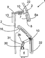
Fig. 3 illustrates the schematic cross sectional views of a flexible program of operating means, and wherein said electromechanical lock can mechanically be operated by said operating means through Bowden cable,
Fig. 4 illustrates the schematic cross sectional views of another operating means, and wherein, the electromechanical lock can be operated by said operating means through linkage, and
Fig. 5 illustrates the schematic cross sectional views of another operating means, and said operating means is provided with strong lock cell, and cover sheet is pure mechanically operation in this operating means, and
Fig. 6 illustrates the schematic cross sectional views of the operating means of Fig. 5, but wherein, cover sheet moves to its operating position by motor, and
Fig. 7 illustrates the schematic cross sectional views of the power lock cell in the operating means of Fig. 5.
The specific embodiment
Vertical view with the movable part front side in Fig. 1 illustrates operations according to the instant invention device 1, and said movable part is depicted as car door under present case.Here in the lower area of operating means 1, be provided with movably cover sheet 3, above cover sheet, be adjacent to be provided with and be designed to movably front cover plate 8 equally.As schematically illustrated, movably the rear side 24 of front cover plate 8 is provided with executive component 7.For the sake of clarity, in Fig. 1, also show the user like its finger 29 principles of work and power of affacting in the operating means 1 how.For this purpose, cover sheet 3 is arranged in its operating position, thereby discharges the entering to the inside of the housing 2 in the operating means 1.For the said operating means 1 of ergonomic ground operation, adjacent front cover plate 8 is arranged on the top of cover sheet 3.Be appreciated that also it is contemplated that front cover plate 8 also can be arranged on movably cover sheet 3 belows.Same front cover plate 8 can be arranged on the left side or the right side of cover sheet 3.But in order to realize operating means 1 simple operability, front cover plate 8 is set with answering direct neighbor, that is, is provided with cover sheet 3 adjacent ground connection.
Another embodiment at operating means 1 shown in Fig. 2 a.Here cover sheet 3 all is in its resting position with front cover plate 8.In said resting position, operating means 1 forms the continuous surface of not having interruption in other words with respect to the front side 23 of movable part 22.Except little slit, between the front of cover sheet 3 or front cover plate 8 and movable part 22, there is not other vestige demonstration to have operating means 1.In order mobility to be shown, pure schematically illustrated rotation or the swing hinge 11 that is used for front cover plate 8 and cover sheet 3.Said rotation or swing hinge are positioned at the above and below of corresponding cover plate 3 and 8.The position of same electromechanical lock 25 in movable part 22 also is schematically illustrated.Certainly, said electromechanical lock also can be higher or be arranged on the said movable part 22 than the lowland.
Another flexible program at operating means 1 of the present invention shown in Fig. 2 b.Similar with Fig. 2 a, in this operating means 1, cover sheet 3 also is in its resting position with front cover plate 8.But front cover plate 8 is arranged on housing 2 or the movable part 22 through rotation or swing hinge 11 in the side.For example can come frontal cover plate 8 to operate through push front cover plate 8 in the left side.Also it is contemplated that, can from the front side 23 of movable part 22, pull out front cover plate 8 in the left side.In the drawings, the moving direction of front cover plate 8 and cover sheet 3 is respectively by arrow 32 and 33 expressions.
Fig. 3 illustrates another enforcement flexible program, wherein sectional view of the schematically illustrated operating means 1 of Fig. 3 of operating means of the present invention.Here cover sheet 3 is automatically operated through motor 4.The dorsal part 24 of the shield 3a of cover sheet 3 is provided with sensor 5 for this reason, said sensor can confirm the user near and for example send control signal corresponding to the control module that is used to control motor 4 26.For this purpose, can link to each other with said control module 26 through electrical connector 28 with said motor 4 by the said sensor 5 that the proximity transducer of condenser type or induction type is formed.Equally, the user to operating means 1 near confirming through identity generator (be also referred to as the ID generator, do not illustrate).Can be provided with alternatively for this reason and send and/or receiving element 27, said transmission and/or receiving element link to each other with control module 26, to send corresponding signal to control module 26.The position of electrical connector 28 or distribution just illustrate for example.
Now, proximity transducer 5 confirmed the user near after, this sensor provides corresponding signal to control module 26, control module is controlled starter motor 4 in view of the above, automatically cover sheet 3 is moved to the operating position from its resting position.Shown in the operating position, the dorsal part contactor banking stop 16 of cover sheet 3, said backstop is stretched out from the inside of housing 2.Now, in the operating position, cover sheet 3 has for example discharged the entering for user's finger 29, thereby can arrive at and operating operation element 7 with simple mode.Said executive component 7 can directly or through control module 26 provide the signal of telecommunication to electromechanical lock 25 indirectly through slight contact.Can open or lock said movable part 22 now thus.After the user opened or lock said movable part 22, the user decontroled operating means 1 and leave operation device.The user leaves; Particularly its finger 29 leaving from operating means 1 can be confirmed by sensor 5, correspondingly motor 4 is controlled through control module 26 equally; Can close said cover sheet 3 automatically thus, thereby make cover sheet be in its resting position.In the said in front motion, cover sheet 3 is around rotation that is arranged on cover sheet 3 belows or 10 swings of swing point.Additionally can be provided for making cover sheet 3 to be automatically moved to the back-moving spring 6 of resting position from the operating position.A side of extension spring 6 is fixed on the housing 2 for this reason, and opposite side is fixed on the bar handle that stretches out of cover sheet 3.Motor 4 can be arranged in the housing 2 below the rotation of cover sheet 3 or swing point 10, and acts on cover sheet 3 through linkage, gear or steel rope system and to be connected.
Explained under normal circumstances in one section in the above, promptly when lock being carried out the electricity operation, the operation of operations according to the instant invention device 1.But in addition, said operating means 1 can also be used for electromechanical lock 25 is carried out the manual operation of Purely mechanical.According to the present invention front cover plate 8 is provided with on the housing 2 through rotation or swing hinge 11 movably for this reason.Moving of front cover plate 8 can directly affact on the electromechanical lock 25 through Bowden cable 12 or linkage 13.Under the situation about in Fig. 3, existing, front cover plate 8 pulled out from the front side 23 of movable part 22 can cause the rope of Bowden cable 12, producing pulling force, an end of said rope acts on the bar handle 9.Another end of the said rope of Bowden cable 12 and electromechanical lock 25 links to each other, and the mechanically operated pulling force of frontal cover plate 8 is delivered to locks on 25 thus.Cover sheet 3 can be provided with shield 3a or 8a with front cover plate 8, is arranged on the front side 23 of movable part 22 thus operating means 1 good looking appearance.Said shield can be by processing with front side 23 identical materials and/or having an identical color.Shield itself can be arranged on said cover plate 3 and 8 through bonding connection or clamping connection.It is contemplated that equally, to cover sheet 3 and/or front cover plate 8 directly paint, chromium plating or handle with other surface treatments so that operating means 1 good looking appearance be arranged in the said front side 23.Can be additionally on the housing 2 of operating means 1 or in stop element 16 is set, after operation, can make front cover plate 8 accurately arrive its resting position again thus.Here it is contemplated that said backstop 16 can for example connect through screw-nut regulates, and simply said operating means 1 is installed on the movable part 22 with realization.The work that be provided with for cover sheet 3 similarly to be used for cover sheet 3 and the backstop 16 of resting position.
The schematic cross sectional views of the similar operations device 1 among Fig. 3 is shown equally, but the mechanical movement of front cover plate 8 not through Bowden cable 12 but affacts on the said electromechanical lock 25 through linkage 13 in this embodiment in Fig. 4.Power lock cell 14 additionally acts on the said front cover plate 8, and said power lock cell is made up of compression spring 15, and acts on constantly on the said front cover plate 8.Mechanically actuated to operating means 1 realizes through the pressure that acts on the front cover plate 8 in Fig. 4, thus, said front cover plate is pressed in the said front side 23.It is contemplated that equally shown spring 15 is that extension spring and said front cover plate 8 can be pulled out from said front side 23.In this case, for example backstop 16 is being arranged on the housing 2 above the bar handle 9.Abandon in this external this operating means 1 using and send and/or receiving element 27.Cover sheet 3 is operated by motor 4 through rope or hawser.Do not use the Connection Element 30 of rigidity thus, that kind as shown in Figure 3.This has such advantage, that is, even 4 actings of non resistance this moment motor also can be carried out mechanically actuated to cover sheet 3.Even thus in when outage also operation protection cover plate 3 easily.
Another embodiment of operating means 1 of the present invention shown in Fig. 5.Here, make firmly lock cell 14 equally, so as movably front cover plate 8 be designed to its resting position be similar to fixing.Only be used in and overcome after the predetermined resistance, front cover plate 8 is moved.In Fig. 7, show in detail similar power lock cell 14.Said power lock cell has clamping connector 17, thus can be for example through bar handle 9 indirectly or directly landform said front cover plate 8 is remained in the said resting position sealedly.The difference of this embodiment of operating means 1 is in addition, the special Connection Element 30 between cover sheet 3 and the motor 4.This Connection Element 30 has slotted hole 31, and said slotted hole is used to guide the pin 3b on the bar handle of cover sheet 3.In Fig. 5, with cover sheet 3 manually-not by its operating position of motor 4-transfer to.Through making cover sheet 3 move to the operating position from resting position, the guide pin 3b of cover sheet 3 can slide in the slotted hole 31 of Connection Element 30 from the top down.Through additional torsionspring 6, cover sheet 3 can automatically be transferred in its resting position.The guide pin 3b of cover sheet 3 will slide in slotted hole 31 from bottom to top this moment.
In contrast, in Fig. 6, cover sheet 3 is drawn to its operating position by motor 4.The Connection Element 30 that has slotted hole 31 is exactly to be used for this purpose.At this moment, the guide pin 3b of cover sheet 3 does not reciprocatingly slide in slotted hole 31, because guide pin is positioned at the backstop place, top of slotted hole 31 all the time.In this case, the reset force of necessity that is used for cover sheet 3 is also by torsionspring 6 generations in the zone that between housing and cover sheet 3, is arranged on the point of rotation 10.In Fig. 5 and 6, the electromechanical lock 25 that does not illustrate is through additionally mechanically operation of linkage 13.
Illustrate in Fig. 7 exemplified and not to be to act on constantly power lock cell 14 on the front cover plate 8, that have clamping connector 17.Here in the resting position of front cover plate 8, for example be arranged on the keeper 18 on the housing 2 and be bonded on the sealed connection of formation shape between the bar handle 9 on the front cover plate 8.For this purpose, a plurality of particularly spherical recesses 19 can be set on bar handle 9, said recess with stretch out from keeper 18 by spring-loaded fulcrum post 20 actings in conjunction.Fulcrum post 20 can have spherical head equally, and this head design becomes and spherical notch 19 is complementary.In resting position, fulcrum post 20 joins in the recess 19 with its head shape sealedly, thus the resistance of effect hope.If apply pulling force or pressure to front cover plate 8 movably now, the then said spring that will cause said bar handle 9 also to resist fulcrum post that moves is pressed into said two fulcrum posts 20 in the keeper 18.In case fulcrum post 20 is not reengaged in the said recess 19, then also no longer effect of the resistance of the regulation of power lock cell 14.Can after overcoming said resistance, operate said movably front cover plate 8 like a cork thus, mechanically to operate said lock 25.After operation, be connected with keeper 18 shapes again through fulcrum post 20 through making bar handle 9 sealedly, can make front cover plate 8 come back to resting position.Through the accurate setting of recess 19 in bar handle 9, can realize accurate location to resting position, said recess also can be used as stop element thus.Current clamping connector 17 is exemplary embodiment, because also can have the left side with corresponding left side or right side recess 19 or the fulcrum post 20 on right side.Same fulcrum post 20 also can be designed to other form.For example this does not depend on that power lock cell 14 is on which position acts on movably front cover plate 8.For example the power lock cell can be in the left side or the right side act directly on the front cover plate 8.
At last, be also pointed out that short ofly to foreclose clearly that the technical characterictic of the operating means 1 that is obtained by each single embodiment also can at random make up.Equally, that the embodiment shown in the operating means 1 can also comprise that other does not illustrate is electric, the member of electronics or machinery.
Reference numerals list:
1 operating means
2 housings
3 cover sheets
3a is used for the shield of cover sheet
The pin of 3b cover sheet
4 are used for the motor of cover sheet
5 sensors
6 back-moving springs
7 executive components
8 front cover plates
8a is used for the shield of front cover plate
The bar handle of 9 front cover plates
The rotation of 10 cover sheets or front cover plate or swing point
11 cover sheets or front cover plate hinge
12 have the Bowden cable of rope
13 linkages
14 power lock cells
15 springs
16 are used for the backstop of cover sheet or front cover plate
17 clamping connectors
18 keepers
19 recesses
20 fulcrum posts
21 springs
22 movable parts
23 front sides
24 dorsal parts
25 locks
26 control modules
27 send and/or receiving element
28 electrical connectors
29 users' finger
30 Connection Elements
Slotted hole in 31 Connection Elements
The arrow that moves of 32 indication cover sheets
The arrow that moves of 33 indication front cover plates
Claims (14)
1. an electromechanical that is used to open and/or lock the movable part (22) of vehicle is locked the operating means (1) of (25), and said operating means has:
Housing (2),
Cover sheet (3) movably; This cover sheet (3) is arranged on the movable part (22) of said housing (2) or said vehicle through rotation or swing hinge (11); User (29) through said cover sheet can conjugation to the inside of operating means (1), and
Be arranged on the executive component (7) that is used for said lock (25) is carried out the electricity operation in the said housing (2),
It is characterized in that,
Said operating means also is provided with adjacent front cover plate (8) movably, can mechanically operate said lock (25) thus.
2. operating means according to claim 1 (1); It is characterized in that; Said cover sheet (3) is operated by motor (4); Wherein can detect user (29) approaching to operating means (1), can retract cover sheet (3) automatically near process said thus through the sensor (5) that is used to control motor (4).
3. operating means according to claim 2 (1) is characterized in that, said sensor (5) be arranged on that said cover sheet (3) is gone up or in.
4. according to each the described operating means (1) in the claim 1 to 3, it is characterized in that, said executive component (7) be arranged on that said movably front cover plate (8) is gone up or in.
5. according to each the described operating means (1) in the claim 1 to 3, it is characterized in that said movably front cover plate (8) is arranged on the movable part (22) of housing (2) or vehicle through a plurality of rotations or swing hinge (11).
6. according to each the described operating means (1) in the claim 1 to 3; It is characterized in that; Bowden cable (12) or linkage (13) act on the said movably front cover plate (8), thus can with the mechanically moving formula of said front cover plate (8) be delivered on the said lock (25).
7. according to each the described operating means (1) in the claim 1 to 3, it is characterized in that, affact on the said lock (25) to said movably front cover plate (8) direct mechanical.
8. according to each the described operating means (1) in the claim 1 to 3, it is characterized in that said cover sheet (3) and/or said movably front cover plate (8) are complementary in the outer shape of resting position and said movable part (22).
9. according to each the described operating means (1) in the claim 1 to 3; It is characterized in that; Said front cover plate (8) can be pulled out from the outer shape of movable part (22), and perhaps said front cover plate (8) can be pressed in the outer shape of movable part (22).
10. operating means according to claim 1 (1); It is characterized in that; Power lock cell (14) is connected with said movably front cover plate (8) effect and applies resistance to said front cover plate (8) directly or indirectly, only after overcoming said resistance, just can make said front cover plate (8) move away resting position thus.
11. operating means according to claim 10 (1) is characterized in that said resistance is greater than 60N.
12., it is characterized in that said power lock cell (14) comprises the spring (15) that is used to produce resistance according to claim 10 or 11 described operating means (1).
13. according to claim 10 or 11 described operating means (1); It is characterized in that; Said power lock cell (14) has clamping connector (17); After overcoming said resistance, can operate said front cover plate (8) like a cork thus, wherein said clamping connector (17) indirectly or directly with said front cover plate (8) with sealed form remain in the resting position.
14. vehicle that has according to each the described operating means (1) in the aforesaid right requirement.
Applications Claiming Priority (3)
| Application Number | Priority Date | Filing Date | Title |
|---|---|---|---|
| DE102006027473.3 | 2006-06-12 | ||
| DE102006027473A DE102006027473A1 (en) | 2006-06-12 | 2006-06-12 | Actuator I |
| PCT/EP2007/055505 WO2007144294A1 (en) | 2006-06-12 | 2007-06-05 | Actuating device |
Publications (2)
| Publication Number | Publication Date |
|---|---|
| CN101460691A CN101460691A (en) | 2009-06-17 |
| CN101460691B true CN101460691B (en) | 2012-04-18 |
Family
ID=38476165
Family Applications (1)
| Application Number | Title | Priority Date | Filing Date |
|---|---|---|---|
| CN200780020893.4A Expired - Fee Related CN101460691B (en) | 2006-06-12 | 2007-06-05 | Actuating device |
Country Status (5)
| Country | Link |
|---|---|
| EP (1) | EP2032783B1 (en) |
| CN (1) | CN101460691B (en) |
| AT (1) | ATE478221T1 (en) |
| DE (2) | DE102006027473A1 (en) |
| WO (1) | WO2007144294A1 (en) |
Families Citing this family (31)
| Publication number | Priority date | Publication date | Assignee | Title |
|---|---|---|---|---|
| DE102009045871A1 (en) * | 2009-10-20 | 2011-04-28 | Huf Hülsbeck & Fürst Gmbh & Co. Kg | handle device |
| KR101199061B1 (en) * | 2010-06-11 | 2012-11-07 | 현대자동차주식회사 | Handle for door trim |
| ITMI20110323A1 (en) * | 2011-03-02 | 2012-09-03 | Automobili Lamborghini Spa | HANDLE FOR VEHICLES |
| DE202011104328U1 (en) | 2011-08-12 | 2011-09-19 | Automobili Lamborghini S.P.A. | Handle for motor vehicles |
| EP2885476B1 (en) * | 2012-08-16 | 2020-10-28 | Huf Hülsbeck & Fürst GmbH & Co. KG | Door handle unit having a safety function |
| DE102013102106A1 (en) * | 2013-03-04 | 2014-09-04 | Huf Hülsbeck & Fürst Gmbh & Co. Kg | Outside door handle arrangement |
| GB2514332B (en) * | 2013-04-30 | 2018-02-07 | Ford Global Tech Llc | Tailgate handle |
| DE102013012489A1 (en) * | 2013-07-26 | 2015-01-29 | Brose Fahrzeugteile Gmbh & Co. Kommanditgesellschaft, Hallstadt | Door handle system for a vehicle door |
| DE102013109914A1 (en) | 2013-09-10 | 2015-03-12 | BROSE SCHLIEßSYSTEME GMBH & CO. KG | Cover flap arrangement for a handle arrangement of a motor vehicle door |
| CN104832011B (en) * | 2014-12-17 | 2017-10-13 | 北汽福田汽车股份有限公司 | Door handle cladding system, car door and vehicle |
| EP3179020B1 (en) * | 2015-12-07 | 2019-04-24 | Huf Hülsbeck & Fürst GmbH & Co. KG | Door handle assembly of a motor vehicle |
| DE102015122365A1 (en) | 2015-12-07 | 2017-06-08 | Huf Hülsbeck & Fürst Gmbh & Co. Kg | Door handle assembly for a motor vehicle |
| SI3234284T1 (en) * | 2016-03-09 | 2018-12-31 | Pirnar, trzenje, proizvodnja in razvoj, d.o.o | Door handle assembly and process for extending and retracting of door handle assembly |
| ITUA20163260A1 (en) * | 2016-05-09 | 2017-11-09 | Gi Gar S R L | COMPLETE HANDLE COMPLETELY BUILT-IN AND COMPLETELY BUILT-IN LOCK. |
| DE102017012026A1 (en) * | 2017-12-22 | 2019-06-27 | Huf Hülsbeck & Fürst Gmbh & Co. Kg | Motor vehicle door handle assembly with operating module |
| DE102017012025A1 (en) * | 2017-12-22 | 2019-06-27 | Huf Hülsbeck & Fürst Gmbh & Co. Kg | Motor vehicle door handle assembly with emergency lever |
| DE102018106657A1 (en) * | 2018-03-21 | 2019-09-26 | Kiekert Ag | Door handle module |
| FR3079864B1 (en) * | 2018-04-10 | 2022-07-22 | Renault Sas | DEVICE FOR OPENING AN OPENING VEHICLE AND VEHICLE EQUIPPED WITH SUCH A DEVICE |
| FR3082864B1 (en) * | 2018-06-22 | 2020-07-17 | U-Shin Italia S.P.A. | OPENING HANDLE ASSEMBLY WITH ELECTRIC UNLOCKING SYSTEM |
| DE102018117961A1 (en) * | 2018-07-25 | 2020-01-30 | Huf Hülsbeck & Fürst Gmbh & Co. Kg | Handle arrangement of a motor vehicle |
| GB2580395A (en) * | 2019-01-09 | 2020-07-22 | Dyson Technology Ltd | Vehicle door latch assembly |
| GB2580394A (en) * | 2019-01-09 | 2020-07-22 | Dyson Technology Ltd | A vehicle door |
| DE102019102266A1 (en) * | 2019-01-30 | 2020-07-30 | Bayerische Motoren Werke Aktiengesellschaft | Actuating device of an opening and closing device |
| JP7218610B2 (en) * | 2019-02-26 | 2023-02-07 | 株式会社アイシン | Vehicle door handle device |
| KR20200107454A (en) * | 2019-03-08 | 2020-09-16 | 휴렛-팩커드 디벨롭먼트 컴퍼니, 엘.피. | Structure to selectively expose grip portion of toner cartridge |
| DE102019109395B4 (en) * | 2019-04-10 | 2023-08-24 | Dr. Ing. H.C. F. Porsche Aktiengesellschaft | vehicle door |
| DE102019119529A1 (en) | 2019-07-18 | 2021-01-21 | Volkswagen Aktiengesellschaft | Door opening device and door opening system for a motor vehicle |
| US11851920B2 (en) | 2020-04-28 | 2023-12-26 | Magna Mirrors Of America, Inc. | Vehicular exterior door handle assembly with light projection and gesture sensing |
| CN111425064B (en) * | 2020-05-06 | 2021-09-03 | 合肥华凌股份有限公司 | Door assembly and storage cabinet |
| US20240044170A1 (en) * | 2021-04-14 | 2024-02-08 | CARROLL Debra | Vehicle occupancy reminder flap for exiting driver |
| EP4108872A1 (en) * | 2021-06-24 | 2022-12-28 | U-Shin France | Vehicle opening element handle assembly |
Citations (6)
| Publication number | Priority date | Publication date | Assignee | Title |
|---|---|---|---|---|
| US5560659A (en) * | 1994-11-04 | 1996-10-01 | Adac Plastics, Inc. | Door handle assembly |
| EP0893561A1 (en) * | 1997-07-25 | 1999-01-27 | Mannesmann VDO Aktiengesellschaft | Handle for a closing device |
| DE19847212A1 (en) * | 1998-10-13 | 2000-04-20 | Daimler Chrysler Ag | Motor vehicle door with recessed handle, operated by putting hand through opening in panel that can be closed with movable plate |
| DE10134993A1 (en) * | 2001-07-18 | 2003-02-06 | Bayerische Motoren Werke Ag | Motor vehicle door opening grip has sprung, hinged plate in moulding having fixed part which can be accessed to open door |
| WO2004079137A2 (en) * | 2003-03-05 | 2004-09-16 | Kiekert Aktiengesellschaft | Motor vehicle |
| EP1402138B1 (en) * | 2001-07-05 | 2005-11-16 | Huf Hülsbeck & Fürst GmbH & Co. KG | Door handle equipped with an automatic retractable flap |
Family Cites Families (4)
| Publication number | Priority date | Publication date | Assignee | Title |
|---|---|---|---|---|
| DE224538C (en) * | ||||
| DE29802678U1 (en) * | 1998-02-17 | 1998-05-14 | Degler Reinhard | Alarm system for vehicles |
| DE10144151C1 (en) * | 2001-09-07 | 2003-07-17 | Huf Huelsbeck & Fuerst Gmbh | Device for actuating a door, a flap or the like, in particular on vehicle doors |
| DE102004058874A1 (en) * | 2004-12-06 | 2006-06-08 | Huf Hülsbeck & Fürst Gmbh & Co. Kg | Outside door handle for a motor vehicle |
-
2006
- 2006-06-12 DE DE102006027473A patent/DE102006027473A1/en not_active Withdrawn
-
2007
- 2007-06-05 WO PCT/EP2007/055505 patent/WO2007144294A1/en active Application Filing
- 2007-06-05 EP EP07729887A patent/EP2032783B1/en not_active Not-in-force
- 2007-06-05 CN CN200780020893.4A patent/CN101460691B/en not_active Expired - Fee Related
- 2007-06-05 DE DE502007004803T patent/DE502007004803D1/en active Active
- 2007-06-05 AT AT07729887T patent/ATE478221T1/en active
Patent Citations (6)
| Publication number | Priority date | Publication date | Assignee | Title |
|---|---|---|---|---|
| US5560659A (en) * | 1994-11-04 | 1996-10-01 | Adac Plastics, Inc. | Door handle assembly |
| EP0893561A1 (en) * | 1997-07-25 | 1999-01-27 | Mannesmann VDO Aktiengesellschaft | Handle for a closing device |
| DE19847212A1 (en) * | 1998-10-13 | 2000-04-20 | Daimler Chrysler Ag | Motor vehicle door with recessed handle, operated by putting hand through opening in panel that can be closed with movable plate |
| EP1402138B1 (en) * | 2001-07-05 | 2005-11-16 | Huf Hülsbeck & Fürst GmbH & Co. KG | Door handle equipped with an automatic retractable flap |
| DE10134993A1 (en) * | 2001-07-18 | 2003-02-06 | Bayerische Motoren Werke Ag | Motor vehicle door opening grip has sprung, hinged plate in moulding having fixed part which can be accessed to open door |
| WO2004079137A2 (en) * | 2003-03-05 | 2004-09-16 | Kiekert Aktiengesellschaft | Motor vehicle |
Also Published As
| Publication number | Publication date |
|---|---|
| EP2032783B1 (en) | 2010-08-18 |
| DE502007004803D1 (en) | 2010-09-30 |
| WO2007144294A1 (en) | 2007-12-21 |
| DE102006027473A1 (en) | 2007-12-13 |
| ATE478221T1 (en) | 2010-09-15 |
| EP2032783A1 (en) | 2009-03-11 |
| CN101460691A (en) | 2009-06-17 |
Similar Documents
| Publication | Publication Date | Title |
|---|---|---|
| CN101460691B (en) | Actuating device | |
| CN102597392B (en) | Handle device having a mechanical return mechanism | |
| US20080084074A1 (en) | Exterior Door Handle For A Motor Vehicle | |
| CN105209703B (en) | Vehicle door latch control device | |
| JP5732795B2 (en) | Vehicle door handle device | |
| KR101737768B1 (en) | Locking apparatus for a vehicle seat | |
| AU758634B2 (en) | Device for activating an opening mechanism and/or a closing mechanism for lockable moving parts on vehicles, such as flaps, doors or similar | |
| US9771747B2 (en) | Door pop-up system | |
| KR102087347B1 (en) | Motor-vehicle door lock | |
| KR101567215B1 (en) | Device for opening and closing fuel door of push open type | |
| DE19547727A1 (en) | Servo-driven door lock for vehicle | |
| WO2014186872A1 (en) | Mechanical assist mechanism for active pedestrian safety latch | |
| CN102575488B (en) | With the handle device of shell-type supporting arrangement | |
| EP2788230A1 (en) | Components for active pedestrian safety mechanism | |
| CN110273601A (en) | The device for opening with linear actuators for motor vehicles | |
| CN105960498A (en) | Door-handle system for vehicles | |
| EP0920561A1 (en) | Circuit for controlling an electrically operated motor vehicle door lock or similar | |
| EP0959205B1 (en) | Vehicle door lock | |
| CN110416910B (en) | Switch cabinet and valve driving mechanism with self-locking function | |
| CN102264991A (en) | Handle for doors or panels, especially on vehicles | |
| CN101649701A (en) | Automobile door lock switching mechanism | |
| WO2022064065A1 (en) | Sliding charging inlet cover | |
| CN107644773A (en) | Toggle switch actuating mechanism | |
| US20120000950A1 (en) | Luggage Container for Fastening to a Vehicle, in Particular to a Motorcycle | |
| CN212507836U (en) | Vehicle door stay assembly |
Legal Events
| Date | Code | Title | Description |
|---|---|---|---|
| C06 | Publication | ||
| PB01 | Publication | ||
| C10 | Entry into substantive examination | ||
| SE01 | Entry into force of request for substantive examination | ||
| C14 | Grant of patent or utility model | ||
| GR01 | Patent grant | ||
| CF01 | Termination of patent right due to non-payment of annual fee |
Granted publication date: 20120418 |
|
| CF01 | Termination of patent right due to non-payment of annual fee |