CN101290979B - Automatic rapid plug-in mechanism - Google Patents
Automatic rapid plug-in mechanism Download PDFInfo
- Publication number
- CN101290979B CN101290979B CN2007101458021A CN200710145802A CN101290979B CN 101290979 B CN101290979 B CN 101290979B CN 2007101458021 A CN2007101458021 A CN 2007101458021A CN 200710145802 A CN200710145802 A CN 200710145802A CN 101290979 B CN101290979 B CN 101290979B
- Authority
- CN
- China
- Prior art keywords
- plug
- battery pack
- assembly
- battery case
- jack body
- Prior art date
- Legal status (The legal status is an assumption and is not a legal conclusion. Google has not performed a legal analysis and makes no representation as to the accuracy of the status listed.)
- Expired - Fee Related
Links
Images


Classifications
-
- Y—GENERAL TAGGING OF NEW TECHNOLOGICAL DEVELOPMENTS; GENERAL TAGGING OF CROSS-SECTIONAL TECHNOLOGIES SPANNING OVER SEVERAL SECTIONS OF THE IPC; TECHNICAL SUBJECTS COVERED BY FORMER USPC CROSS-REFERENCE ART COLLECTIONS [XRACs] AND DIGESTS
- Y02—TECHNOLOGIES OR APPLICATIONS FOR MITIGATION OR ADAPTATION AGAINST CLIMATE CHANGE
- Y02E—REDUCTION OF GREENHOUSE GAS [GHG] EMISSIONS, RELATED TO ENERGY GENERATION, TRANSMISSION OR DISTRIBUTION
- Y02E60/00—Enabling technologies; Technologies with a potential or indirect contribution to GHG emissions mitigation
- Y02E60/10—Energy storage using batteries
Landscapes
- Details Of Connecting Devices For Male And Female Coupling (AREA)
Abstract
本发明涉及自动快速插接机构,所述插接机构包括设置在电池组插入电池箱内部的电池组后端面上的至少两个插孔组件;设置在电池箱内部与所述电池组后端面相对的侧面上的至少两个插头组件;其中,插孔组件具有弹性夹紧和回缩能力,插头组件具有弹性定心功能;将电池组以抽屉的形式推入电池箱内时,插头组件能自动顺利的插入所述插孔中。借助插头组件与插孔组件的功能和配合效果,以吸收插孔和插头组件在制造和装配时引起的同轴度误差;能克服电池组相对于箱体的震动及箱体相对于车体的震动;保证安全的通过所述插头组件输出所述电池组的电力。本发明满足了高电压、大电流下的电器件自动快速插接条件,实现了电池组的快装快卸性能。
The invention relates to an automatic fast plug-in mechanism, the plug-in mechanism includes at least two socket assemblies arranged on the rear end surface of the battery pack inserted into the battery box; and arranged inside the battery box opposite to the rear end surface of the battery pack There are at least two plug assemblies on the side of the box; among them, the jack assembly has elastic clamping and retraction capabilities, and the plug assembly has an elastic centering function; when the battery pack is pushed into the battery box in the form of a drawer, the plug assembly can automatically Insert it smoothly into the jack. With the help of the function and cooperation effect of the plug assembly and the jack assembly, the coaxiality error caused by the jack and plug assembly during manufacture and assembly can be absorbed; the vibration of the battery pack relative to the box body and the vibration of the box body relative to the car body can be overcome. Vibration; ensuring safe output of the electric power of the battery pack through the plug assembly. The invention satisfies the conditions of automatic fast insertion and connection of electric devices under high voltage and high current, and realizes the quick assembly and quick disassembly performance of the battery pack.
Description
技术领域 technical field
本发明涉及适于电动汽车技术领域的自动快速插接机构。更具体地说,涉及应用于电动汽车的电池组和电池箱的自动快速插接机构。The invention relates to an automatic fast plug-in mechanism suitable for the technical field of electric vehicles. More specifically, it relates to an automatic quick plug-in mechanism applied to battery packs and battery boxes of electric vehicles.
背景技术 Background technique
有限的石油资源和环境污染问题的日益突出,使得电动汽车越来越引起社会的重视,电动汽车成了未来汽车的发展方向。电动汽车上的核心技术之一是能源储备及供给系统,解决好蓄电池的使用技术便成了电动车产业化发展的技术关键。现有的电动汽车(如大客车)的电池单体是经过导线串联,单体间仅用导线连接裸装在金属箱内。每个电池箱之间的动力连线用手动插头连接,放在两侧仓门人易接近处;这样就带来电池连线太长,回路电压降大,电量输出小,电力损失多等诸多问题。此外,单体电池裸装在金属箱内,不能防水,防尘,防震,极易产生自放电,产生松动和接触电阻,影响电池的一致性和功率输出。而且,整箱螺栓固定,不能实现整体快装和快卸,不能用快换电池的方式扩大续使里程,特别是锂电池等有机物电池具有在误用时易燃的特点,其推广使用必须具备与汽车快速分离的安全条件。如此,造成锂电池这一高能量密度的电池难于推广,为解决这一技术问题就需要一种自动快速插接机构,使电池组能快速与汽车分离,而以往没有适宜直流高压,大电流,动态接插的接插件,为此,提出了本发明的技术方案。Limited oil resources and increasingly prominent environmental pollution problems have drawn more and more attention from the society to electric vehicles, and electric vehicles have become the development direction of future automobiles. One of the core technologies of electric vehicles is the energy storage and supply system. Solving the use of battery technology has become the technical key to the industrialization of electric vehicles. The battery monomers of existing electric vehicles (such as buses) are connected in series through wires, and the monomers are only connected with wires and are bare-packed in metal boxes. The power connection between each battery box is connected with a manual plug and placed at the door on both sides where people can easily access; this will cause many problems such as too long battery connection, large loop voltage drop, small power output, and large power loss. . In addition, the single battery is packaged in a bare metal box, which is not waterproof, dustproof, and shockproof, and is prone to self-discharge, resulting in looseness and contact resistance, which affects the consistency and power output of the battery. Moreover, the whole box is fixed with bolts, so it cannot be quickly installed and unloaded, and the mileage cannot be extended by quick battery replacement. In particular, organic batteries such as lithium batteries are flammable when misused, and their promotion and use must be compatible with Safety conditions for rapid separation of cars. In this way, it is difficult to popularize the lithium battery, a high energy density battery. To solve this technical problem, an automatic quick plug-in mechanism is needed to quickly separate the battery pack from the car. In the past, there was no suitable DC high voltage, high current, The connector of dynamic plugging, for this reason, proposes the technical scheme of the present invention.
发明内容 Contents of the invention
本发明的目的是提供一种应用于电池组和电池箱的自动快速插接机构,以保证插头和插孔在接插过程中,吸收同轴度误差带来的插接困难,使应用于电池组和电池箱的插孔的直径在一定范围内可扩大和缩小,并受有颈项力夹紧,以及配合相应的导线连接,确保正常的电力输出。The purpose of the present invention is to provide an automatic fast plug-in mechanism applied to battery packs and battery boxes, so as to ensure that plugs and sockets can absorb the plug-in difficulties caused by coaxiality errors during the plug-in process, so that it can be applied to batteries. The diameters of the sockets of the battery pack and the battery box can be expanded and reduced within a certain range, and are clamped by the neck force, and connected with corresponding wires to ensure normal power output.
为了实现上述目的,本发明给出了一种应用于电池组和电池箱的自动快速插接机构,该电池箱具有至少一个开放侧面的箱体结构,电池组从所述至少一个开放侧面以抽屉的形式插入所述电池箱,所述自动快速插接机构包括:设置在插入电池箱内部的电池组后端面上的至少两个插孔组件,所述至少两个插孔组件中的一个与所述电池组的正电极连接,并且所述至少两个插孔组件中的另一个与所述电池组的负电极连接;设置在电池箱内部与所述电池组后端面相对的后面上的至少两个插头组件;其中,所述插孔组件具有弹性夹紧力和回缩力,在将所述电池组以抽屉的形式推入所述电池箱内时,所述插头组件插入所述插孔组件,使得所述电池组在所述电池箱内,借助所述插头组件与所述插孔组件的配合,通过所述插头组件输出所述电池组的电力。In order to achieve the above object, the present invention provides an automatic quick plug-in mechanism applied to a battery pack and a battery box, the battery box has a box structure with at least one open side, and the battery pack is drawn from the at least one open side The automatic quick plug-in mechanism includes: at least two socket assemblies arranged on the rear end face of the battery pack inserted into the battery box, one of the at least two socket assemblies is connected to the battery box The positive electrode of the battery pack is connected, and the other of the at least two jack components is connected to the negative electrode of the battery pack; a plug assembly; wherein, the jack assembly has elastic clamping force and retraction force, and when the battery pack is pushed into the battery box in the form of a drawer, the plug assembly is inserted into the jack assembly , so that the battery pack is in the battery box, and the power of the battery pack is output through the plug assembly through the cooperation of the plug assembly and the jack assembly.
换句话说,借助所述插头组件与所述插孔组件的功能和配合效果,能吸收插孔组件和插头组件在制造和装配时引起的同轴度误差;能克服电池组相对于箱体的震动及箱体相对于车体的震动;保证安全的通过所述插头组件输出所述电池组的电力。In other words, with the help of the function and cooperation effect of the plug assembly and the jack assembly, the coaxiality error caused by the jack assembly and the plug assembly during manufacture and assembly can be absorbed; Vibration and vibration of the box body relative to the vehicle body; ensuring safe output of the electric power of the battery pack through the plug assembly.
最好,所述插孔组件包括插孔本体,该插孔本体具有沿中心轴线上对称的、在插孔本体壁上形成一对切口。Preferably, the socket assembly includes a socket body having a pair of notches formed on the wall of the socket body symmetrically along the central axis.
最好,所述插孔组件此外还包括导电片、垫片、底座和弹簧,导电片具有前竖直部分、后竖直部分和水平部分,水平部分固定在底座上,并且后竖直部分上具有定位凸起,由该定位凸起使弹簧定位并且借助弹簧将垫片抵靠在前竖直部分上,前竖直部分上具有通孔,所述插孔本体具有凸缘,该凸缘将插孔本体的外部划分前外壁部分和后外壁部分,所述插孔本体的后外部部分穿过所述前竖直部分上的所述通孔进而穿过垫片并且穿入所述弹簧内部。Preferably, the jack assembly also includes a conductive sheet, a gasket, a base and a spring, the conductive sheet has a front vertical part, a rear vertical part and a horizontal part, the horizontal part is fixed on the base, and the rear vertical part is There is a positioning protrusion, the spring is positioned by the positioning protrusion and the gasket is pressed against the front vertical part by means of the spring. The front vertical part has a through hole, and the jack body has a flange, which will The outside of the jack body is divided into a front outer wall portion and a rear outer wall portion, the rear outer portion of the jack body passing through the through hole on the front vertical portion and then through the washer and into the spring interior.
最好,所述插孔本体上设置有至少一个沿插孔本体的径向夹紧该插孔本体的箍簧。Preferably, the socket body is provided with at least one hoop spring clamping the socket body along the radial direction of the socket body.
最好,所述切口是贯通所述插孔本体的。Preferably, the cutout runs through the jack body.
最好,所述切口是不贯通所述插孔本体的。Preferably, the cutout does not go through the jack body.
最好,所述插孔组件和所述插头组件中,至少一个配备有弹性定心圈,用以吸收由制造和震动引起的插孔组件和插头组件不同轴带来的误差。Preferably, at least one of the socket assembly and the plug assembly is equipped with an elastic centering ring to absorb errors caused by misalignment of the socket assembly and the plug assembly caused by manufacturing and vibration.
最好,所述插孔组件包括插孔本体,所述插孔本体包括线簧内部体和线簧外部体。Preferably, the jack assembly includes a jack body, and the jack body includes a wire spring inner body and a wire spring outer body.
最好,所述插孔组件此外还包括外套壳体、压盖、定位螺母和固定螺栓,所述外套壳体具有内孔,所述插孔本体插入在该内孔内,并且由压盖将所述插孔本体压紧在所述内孔内,所述定位螺母用于使所述插孔组件固定在电池组或电池箱的壁上,固定螺栓用于将压盖固定在外套壳体上。Preferably, the jack assembly also includes an outer casing, a gland, a positioning nut and a fixing bolt, the outer casing has an inner hole, and the jack body is inserted into the inner hole, and is fixed by the gland. The jack body is pressed into the inner hole, the positioning nut is used to fix the jack assembly on the wall of the battery pack or battery box, and the fixing bolt is used to fix the gland on the casing .
最好,所述插头组件包括插头本体,该插头本体包括插头端头、卡位环、插头固定部分和带有螺纹的插头连接部分,所述插头组件此外还包括套装在插头本体上的内座和外座,在内座和外座之间夹设有弹性定心圈。Preferably, the plug assembly includes a plug body, the plug body includes a plug end, a retaining ring, a plug fixing portion and a threaded plug connection portion, and the plug assembly also includes an inner seat fitted on the plug body and the outer seat, and an elastic centering ring is sandwiched between the inner seat and the outer seat.
采用以上技术方案满足了高电压,大电流,具有同轴度误差的电器件自动快速插接条件。适宜电动车电池箱中整体电池组的快装和快卸,解决了锂电池的安全使用问题;节省电力,方便维护,扩大了续使里程,适宜车载充电和分体充电,进一步满足了电动汽车的要求;对电动汽车的产业化具有重要的意义和作用。Adoption of the above technical scheme meets the conditions of high voltage, high current, and electric devices with coaxiality error for automatic fast insertion. It is suitable for quick installation and quick disassembly of the whole battery pack in the battery box of electric vehicles, which solves the problem of safe use of lithium batteries; saves power, facilitates maintenance, expands the mileage, and is suitable for vehicle charging and split charging, which further meets the needs of electric vehicles. requirements; it is of great significance and role to the industrialization of electric vehicles.
附图说明 Description of drawings
图1表示按照本发明的第一种实施方式的自动快速插接机构1的插孔组件;Fig. 1 shows the jack assembly of the automatic quick-connect mechanism 1 according to the first embodiment of the present invention;
图2是按照本发明的第一种实施方式的插孔组件组装完成后的立体图;Fig. 2 is a perspective view of the assembled socket assembly according to the first embodiment of the present invention;
图3表示插头组件插入到插孔本体中的状态;Fig. 3 shows the state that the plug assembly is inserted into the jack body;
图4表示按照本发明的第二种实施方式的自动快速插接机构的插孔组件;Fig. 4 shows the jack assembly of the automatic quick plug-in mechanism according to the second embodiment of the present invention;
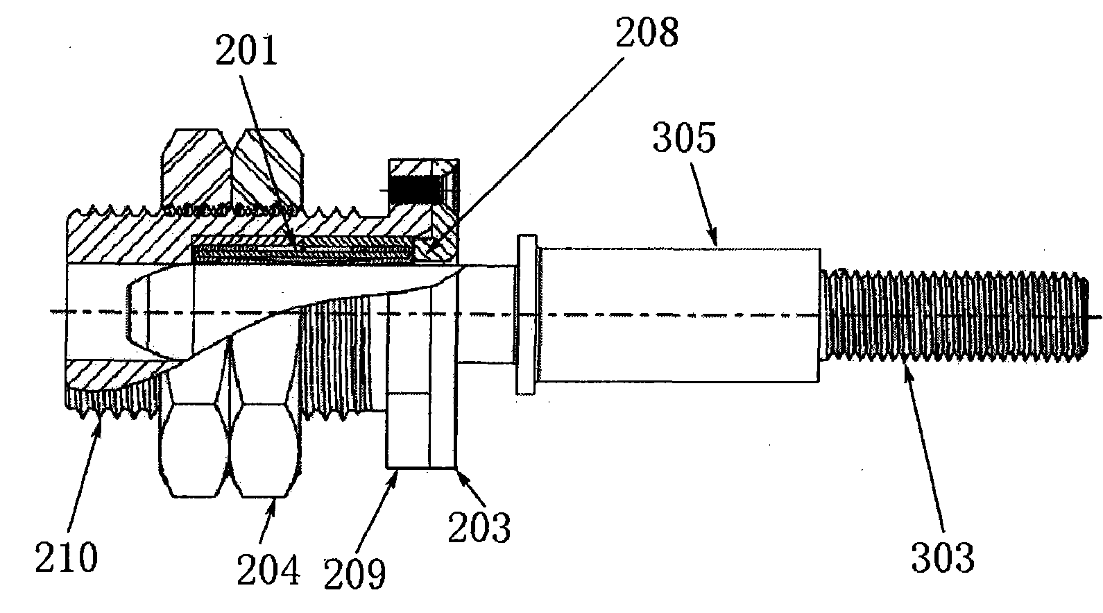
图5是按照本发明的第二实施方式的自动快速插接机构的插孔组件与插头组件插接在一起的状态下的剖视图;Fig. 5 is a cross-sectional view of the socket assembly and the plug assembly of the automatic quick plug-in mechanism according to the second embodiment of the present invention;
图6表示按照本发明的第二实施方式的插孔组件的插孔本体的线簧内部体;Fig. 6 shows the wire spring inner body of the socket body of the socket assembly according to the second embodiment of the present invention;
图7表示按照本发明的第二实施方式的插孔组件的插孔本体;Fig. 7 shows the socket body of the socket assembly according to the second embodiment of the present invention;
图8表示按照本发明的插头组件的插头本体;Figure 8 shows the plug body of the plug assembly according to the present invention;
图9表示按照本发明的电池组的立体图;Figure 9 shows a perspective view of a battery pack according to the invention;
图10、11表示按照本发明的电池箱的立体图;和Figures 10 and 11 represent perspective views of a battery box according to the invention; and
图12表示按照本发明的电池箱与电池组的组装立体图。Fig. 12 shows an assembled perspective view of the battery box and the battery pack according to the present invention.
具体实施方式 Detailed ways
下面将参照附图对本发明的自动快速插接机构进行详细介绍。The automatic quick plug-in mechanism of the present invention will be described in detail below with reference to the accompanying drawings.
图1表示按照本发明的第一种实施方式的自动快速插接机构1的插孔组件10。其中,插孔组件10具有一定的涨开和回缩的能力。如图1所示,插孔组件10包括插孔本体101,该插孔本体101为中空的圆柱体,在该圆柱体的壁上沿其中心轴开有切口108。并且在插孔本体101的两端各固定有一个箍簧102。优选地,箍簧102的内径等于或略大于插孔本体101的外径。这样,在端面直径大于插孔本体101的外侧端口内径的插头本体301插入到插孔本体101内时,插孔本体101能够涨开,并且在箍簧102的回缩力的作用下,能够将插头组件301固定在插孔本体101内。Fig. 1 shows a
按照本发明的一种优选实施方式,插孔本体101壁上的切口108可以是贯穿的切口,也就是,将插孔本体101切为两半,然后用箍簧102将这两半固定起来。According to a preferred embodiment of the present invention, the notch 108 on the wall of the jack body 101 can be a through notch, that is, the jack body 101 is cut into two halves, and then the hoop spring 102 is used to fix the two halves.
按照本发明的另一种优选实施方式,插孔本体101壁上的切口108可以是不贯穿的切口,具体来说,切口108从插孔本体101的外侧端口开始沿插孔本体101的中心轴开到插孔本体101的内侧端口附近,但是不贯通。在这种情况下,可以不采用箍簧,仅仅利用插孔本体101材料本身的弹性来实现涨开和回缩能力。不过,最好采用箍簧102沿插孔本体101的横向在插孔本体101的外壁上的两端夹紧该插孔本体101,这样加大了插孔本体101的回缩力,从而使插孔本体101的紧固性能更佳。According to another preferred embodiment of the present invention, the slit 108 on the wall of the socket body 101 may be a non-through slit, specifically, the slit 108 starts from the outer port of the socket body 101 along the central axis of the socket body 101 Open to the vicinity of the inner port of the jack body 101, but not through. In this case, the hoop spring may not be used, and only the elasticity of the material of the socket body 101 is used to realize expansion and retraction capabilities. However, it is preferable to adopt the hoop spring 102 to clamp the jack body 101 at both ends on the outer wall of the jack body 101 along the transverse direction of the jack body 101, which increases the retraction force of the jack body 101, thereby making the jack body 101 The fastening performance of the hole body 101 is better.
其中,按照本发明的优选实施方式,箍簧102可用标准件卡簧,回缩力最好在5公斤左右。Wherein, according to a preferred embodiment of the present invention, the hoop spring 102 can be a standard clip spring, and the retraction force is preferably about 5 kg.
从图1中可以看出,插孔本体101的外壁上还具有凸缘107,以凸缘107为界,插孔本体101的外壁分为前后两个部分101a和101b,前外壁部分101a沿轴向的长度要比后外壁部分101b沿轴向的长度小得多,并且该凸缘107也是由切口108一分为二的。As can be seen from Fig. 1, a flange 107 is also provided on the outer wall of the jack body 101, and with the flange 107 as a boundary, the outer wall of the jack body 101 is divided into two
如图1所示,插孔组件10此外还包括导电片103、弹簧104、垫片105和底座106。导电片103包括前竖直部分103a、后竖直部分103b和水平部分103c。水平部分103c固定在底座106上。前竖直部分103a比后竖直部分103b的高度要小。前竖直部分103a包括一个通孔(未示出),该通孔的内径略大于插孔本体101的外径并且小于凸缘107的直径。后竖直部分103b包括处于下部的定位凸起109。如图中所示,定位凸起109为圆环形,并且该圆环的圆心与前竖直部分103a上的通孔的圆心相对,也就是,所述两个圆心的连线与水平部分103c平行。该定位凸起109可以为任何形状,并不局限于圆环形,包括圆柱形、棱柱形、锥形、圆锥形、半圆形等等。As shown in FIG. 1 , the
弹簧104借助定位凸起109定位在后竖直部分103b上,并且弹簧104的另一端抵靠在垫片105上,使垫片贴紧前竖直部分103a。垫片105为环形,套在后外壁部分101b上。The spring 104 is positioned on the rear vertical portion 103b by means of the positioning protrusion 109, and the other end of the spring 104 abuts against the spacer 105, so that the spacer is pressed against the front vertical portion 103a. The spacer 105 is annular and fits over the rear
图2是按照本发明的第一种实施方式的插孔组件10组装完成后的立体图。如图2所示,插孔组件10还包括外壳110。外壳110的前端面上具有一个通孔111,该通孔111的直径略大于插孔本体101的外径,但是小于凸缘107的直径,因此将插孔本体101顶住在外壳110之内。而且,外壳110上表面上还具有供后竖直部分101b穿出的开口112,该开口112与外壳110前端面之间的距离是这样的:使凸缘107与前竖直部分101a紧密接触,以实现插孔本体101与导电片103之间的良好导通。此时,在弹簧104的作用下,由于后竖直部分103b被外壳110固定住以致不能进行俯仰运动,因而在插头本体301插入到插孔本体101中时,插头本体301对插孔本体101的轴向推力造成的前竖直部分103a的后仰运动受到弹簧104的阻碍,并且在插头本体301完全插入插孔本体101中而停止对插孔101推动时,前竖直部分103a能够在弹簧104的作用下恢复到初始竖直状态,保证了插头本体301、插头本体101和导电片103之间的良好接触。Fig. 2 is a perspective view of the assembled
如图3所示,表示了插头本体301插入到插孔本体101中的状态。从图中可以看出,底座106上有多个通孔。在安装壳体110时,可以利用螺栓将壳体110固定在底座106,而且这些螺栓会从底座的通孔中穿出(如图2所示),以便继续利用这些螺栓将装配好的插孔组件10安装在需要使用该插孔组件的箱体的壁上。As shown in FIG. 3 , a state in which the
图4表示按照本发明的第二种实施方式的自动快速插接机构1的插孔组件20,图4所示,利用线簧来形成按照本发明另一种实施方式的插孔组件,即在插孔组件内做成弹簧孔,该簧孔可沿径向涨开和收缩,从而夹紧插头组件,回缩力最好在5公斤左右。Fig. 4 shows according to the
具体来说,如图4所示,插孔组件20包括插孔本体201、外套壳体202、压盖203、定位螺母204和固定螺栓205。外套壳体202具有内孔207,插孔本体201插入在该内孔内。并且外套壳体202具有凸缘端部209和螺纹延长体210,在凸缘端部209的端面上具有螺纹孔,凸缘端部209的外径大于螺纹延长体210的外径,而且凸缘端部209的外径可以与压盖203的外径相同。压盖203具有中心孔206和两个小直径的螺栓用固定通孔,该中心孔206的直径等于或略大于插孔本体201的内径并且小于插孔本体201的外径。并且在压盖203朝向插孔本体201的一侧上,围绕着中心孔206的圆周形成有一个环形凸起208(如图5所示)。该环形凸起208的内径与中心孔206相同。环形凸起208的外径小于外套壳体202的内孔207的内径并且大于插孔本体101的外径。这样,在插孔本体201插入到外套壳体202的内孔207内之后,将压盖203盖在外套壳体202的凸缘端部209的端面上,使环形凸起208插入在内孔207内,以将插孔本体201顶住,防止在从插孔本体201中拔出插头时将插孔本体201从内孔207中带出。并且利用固定螺栓205穿过顶盖203上的固定通孔选拧进凸缘端部207端面上的螺纹孔中,将压盖固定在凸缘端部209的端面上。而且,如图5所示,在外套壳体202的内孔207由中心轴重合的两个内孔部分211和212组成,插孔本体201所插入的大直径内孔部分211具有较大直径,该直径等于或略大于插孔本体201的外径。小直径内孔部分212与大直径内孔部分211同轴且相通,但是小直径内孔部分212的直径等于或略大于插孔本体201的内径而且等于或略大于插头本体301插入插孔本体201中的部分的最大直径,同时小于插孔本体201的外径。由此,小直径内孔部分212与大直径内孔部分211之间的交界处形成一台阶面。Specifically, as shown in FIG. 4 , the
定位螺母204借助螺纹延长体210外表面上的螺纹旋拧在外套壳体上,用来将插孔组件20固定在箱体壁上。The
下面参照图6和图7介绍按照本发明第二实施方式的插孔本体201的具体结构和形成过程。图6表示插孔本体201的线簧内部体2011,图7表示插孔本体201。如图6所示,线簧内部体2011是将线簧片环曲成圆柱形并且将该圆柱体两端的部分向圆柱体中部翻折而形成的。这样,使得线簧内部体2011中部的外径要小于两端部的外径,从而使得线簧内部体2011的中部有沿径向向外扩张的空间,在插头本体301插入到插孔本体内的时候,线簧内部体2011的中部能够在插头本体301的挤压下自由地沿径向向外扩张。如图7所示,在线簧内部体2011两端分别套装有一个线簧外部体2012,这两个线簧外部体2012的内径等于或略大于线簧内部体2011两端部的外径,并且这两个线簧外部体2012之间留有预定的间隙2013。The specific structure and forming process of the
在将插孔本体201插入到外套壳体202的内孔207中之后,在安装压盖203时,线簧外部体2012被夹在压盖203的环形凸起208与小直径内孔部分212之间,在拧紧螺栓205的同时,环形凸起208向内孔207内运动,使得两个线簧外部体2012逐渐相互靠近直至紧贴在一起,也就是,直至间隙2013消失。这样,就保证了线簧内部体2011中部向外沿径向扩张的自由空间并且提高了线簧内部体2011的弹力和回缩力。After inserting the
下面参照图3和图8介绍插头组件30的结构。The structure of the
如图8表示插头组件30的插头本体301。插头本体301包括插头端头304、卡位环302、插头固定部分305和带有螺纹的插头连接部分303。其中,插头端头304包括圆锥形顶端3041和圆柱形主体3042。如图3所示,插头组件30还包括内座306和外座307以及弹性定心圈308。内座306、外座307和弹性定心圈308都具有中心孔,插头本体的插头固定部分305插入在这些中心孔中,并且内座306由卡位环302顶住。在将插头组件30安装在箱体的壁上的通孔内时,由内座306和外座307夹住箱体的壁,使弹性定心圈308处于箱体壁上的通孔内。这样,在插孔组件10或20与插头组件30自动插接的时候,当插孔本体101或201与插头端头304之间因不同心而存在匹配偏差时,由于插头端头304具有圆锥形顶端3041,只要圆锥形顶端3041插孔本体101或201内孔的侧壁,插头端头304就可以在弹性定心圈308的帮助下,顺利进入插孔本体101或201内。这是因为,在插头端头304与插孔本体101或201在插接时存在不同心的情况下,圆锥形顶端3041接触到插孔本体101或102的内孔的侧壁就会产生垂直于插头端头304的挤压分力,这个挤压分力会传递到弹性定心圈308上,又由于弹性定心圈308具有弹性并且与箱体壁处于同一平面内且相互接触,因此能够在使得内座306和外座307沿着垂直于插头本体的方向产生相应的移动,从而能够使插头本体301产生相应的横向移动,以致最终使插头端头304插入到插孔本体101或201中。这样,在弹性定心圈308的作用下,吸收了插头本体301和插孔本体101或201之间因不同心而引起的误差,使插接和分开容易。同时,所述弹性定心圈308也吸收电池组相对外箱体的震动,防止插头和插孔之间的相对运动。无需说明,插孔也可以根据需要同时采用弹性定心圈。弹性定心圈308可以采用任何弹性材料制成,例如硅胶等等。FIG. 8 shows the
上述两种实施方式均可实现颈项加紧插头组件。插头组件可根据要求设计成圆柱和锥销,插孔组件也就配成圆柱孔和锥孔。前面介绍的各组成部分,除了弹性定心圈之外,均可以采用导电良好的金属制成,比如铜,当然并不仅仅局限于铜,可以根据需要采用金、银等金属。The above two implementations can realize the neck tightening plug assembly. The plug assembly can be designed as cylindrical and tapered pins according to requirements, and the socket assembly can also be designed as cylindrical holes and tapered holes. The components described above, except the elastic centering ring, can be made of metals with good electrical conductivity, such as copper, of course not limited to copper, and gold, silver and other metals can be used as needed.
下面将参照图9~12介绍按照本发明的自动快速插接机构在电池箱中的应用。图9是按照本发明的电池组40的立体图;图10、11是按照本发明的电池箱的立体图;图12是按照本发明的电池箱与电池组40的组装立体图。The application of the automatic quick plug-in mechanism in the battery box according to the present invention will be introduced below with reference to FIGS. 9-12. 9 is a perspective view of the
如图9所示,按照本发明的电池组40上装配有按照本发明的插孔组件10或20,并且还包括与插孔组件10或20位于同一端面上的定位销402和缓冲垫403。插孔组件10或20与电池组40的正负极电连接。As shown in FIG. 9 , the
如图10所示,按照本发明的电池箱50的后端面上配备有按照本发明的插头组件30,这两个插头组件30的位置与电池组40后端面上的按照本发明的插头组件10或20的位置相对应。并且在按照本发明的电池箱的后端面上还配备有定位孔501,用来供电池组40后端面上的定位销402插入,用于实现插头组件30与插孔组件10或20之间的准确定位。图11是从另一个角度观看的按照本发明的电池箱50的立体图。As shown in Figure 10, the rear end face of the
如图12所示,在将电池组40组装到电池箱50中时,插孔组件10或20会与插头组件30精确地自动插接并且能够借助插孔组件10或20自身的夹紧能力使电池组40固定在电池箱内。这是一种所谓的抽屉式电池箱,也就是和家具桌子抽屉拉出模式一样,开锁后抽屉可拉出与桌子分开。在装配完成之后,自动快速插接机构的插头组件30朝向电池箱50外部的螺纹端是对外输出的正极和负极。所述正极和负极通过插头组件30的插头端头304与电池组40上的插孔组件10或20的连接来获得电力输出。在插接的过程中由定位销402引导插接。As shown in FIG. 12 , when the
插头组件30露在外部的插头连接部分303的螺纹可接动力软线,为保证软线不约束插头的震动,将软线留好余量后固定在外箱体上,这样电池组40相对于电池箱50有间隙震动时,插孔组件10或20的颈项夹紧力大于弹性硅胶圈308和外接软线的变形力,便不会影响插头和插孔的正常输电工作。然后,电池箱50的软线固定端再留好余量与车身连接,这样电池箱50相对车身震动时,也不会影响插头插孔的正常输电工作。The thread of the exposed
如此自动快速插接机构的成功实现,便解决了所谓“自动快速插接抽屉式电池箱”的技术关键,实现了电池组的快装快卸性能,解决了锂电池的安全应用,促进了电动汽车的产业化发展。The successful realization of such an automatic quick plug-in mechanism solves the technical key of the so-called "automatic quick plug-in drawer battery box", realizes the quick loading and unloading performance of the battery pack, solves the safe application of lithium batteries, and promotes the development of electric vehicles. Industrialization of automobiles.
本发明通过上面的实施例进行举例说明,但是,应当理解,本发明并不限于这里所描述的特殊实例和实施方案。在这里包含这些特殊实例和实施方案的目的在于帮助本领域中的技术人员实践本发明。任何本领域中的技术人员很容易在不脱离本发明精神和范围的情况下进行进一步的改进和完善,因此本发明只受到本发明权利要求的内容和范围的限制,其意图涵盖所有包括在由所附权利要求所限定的本发明精神和范围内的备选方案和等同方案。The present invention is illustrated by the above examples, however, it is to be understood that the invention is not limited to the particular examples and embodiments described herein. These specific examples and embodiments are included herein to assist those skilled in the art in practicing the invention. Any person skilled in the art can easily carry out further improvement and perfection without departing from the spirit and scope of the present invention, so the present invention is only limited by the content and scope of the claims of the present invention, and it is intended to cover all Alternatives and equivalents within the spirit and scope of the invention as defined by the appended claims.
Claims (6)
Priority Applications (1)
| Application Number | Priority Date | Filing Date | Title |
|---|---|---|---|
| CN2007101458021A CN101290979B (en) | 2007-08-24 | 2007-08-24 | Automatic rapid plug-in mechanism |
Applications Claiming Priority (1)
| Application Number | Priority Date | Filing Date | Title |
|---|---|---|---|
| CN2007101458021A CN101290979B (en) | 2007-08-24 | 2007-08-24 | Automatic rapid plug-in mechanism |
Publications (2)
| Publication Number | Publication Date |
|---|---|
| CN101290979A CN101290979A (en) | 2008-10-22 |
| CN101290979B true CN101290979B (en) | 2011-11-09 |
Family
ID=40035134
Family Applications (1)
| Application Number | Title | Priority Date | Filing Date |
|---|---|---|---|
| CN2007101458021A Expired - Fee Related CN101290979B (en) | 2007-08-24 | 2007-08-24 | Automatic rapid plug-in mechanism |
Country Status (1)
| Country | Link |
|---|---|
| CN (1) | CN101290979B (en) |
Cited By (1)
| Publication number | Priority date | Publication date | Assignee | Title |
|---|---|---|---|---|
| CN104659307A (en) * | 2015-02-13 | 2015-05-27 | 中国华能集团清洁能源技术研究院有限公司 | Rapidly-replaceable constant-temperature matrix type energy storage box |
Families Citing this family (7)
| Publication number | Priority date | Publication date | Assignee | Title |
|---|---|---|---|---|
| CN101841105B (en) * | 2010-04-01 | 2012-06-20 | 力柏时代锂动力科技(北京)有限公司 | Electrical connector for vehicle |
| CN102354828B (en) * | 2011-08-09 | 2013-09-18 | 普天新能源有限责任公司 | Electrical connecting device of power cell box of electric automobile |
| CN102800832A (en) * | 2012-08-24 | 2012-11-28 | 李辉 | Battery pack fast male-and-female connection structure |
| CN106859502B (en) * | 2017-04-13 | 2018-01-30 | 重庆市桑麻环保科技有限公司 | A kind of Environmental-protection dust removal device |
| CN110071240B (en) * | 2019-04-08 | 2022-04-22 | 河南平高电气股份有限公司 | Battery box guide assembly and energy storage device using same |
| CN110112337B (en) * | 2019-04-08 | 2022-05-17 | 河南平高电气股份有限公司 | Battery box support roller and energy storage device using the same |
| CN110137403B (en) * | 2019-05-05 | 2024-04-16 | 中国科学院电工研究所 | A compact container energy storage system integrated structure |
Citations (4)
| Publication number | Priority date | Publication date | Assignee | Title |
|---|---|---|---|---|
| CN2702485Y (en) * | 2004-05-11 | 2005-05-25 | 北京理工大学 | Quick socket for cable adaptor of electric automobile battery case |
| CN1874073A (en) * | 2006-06-06 | 2006-12-06 | 北京理工大学 | Dedicated quick jack, plug for battery pack of electric motor car |
| CN1885587A (en) * | 2006-06-06 | 2006-12-27 | 北京理工大学 | Standardized battery case of electric vehicle |
| CN2932629Y (en) * | 2006-08-07 | 2007-08-08 | 翟书章 | Drawer-type electric vehicle storage battery, accessory tool and charging battery frame |
-
2007
- 2007-08-24 CN CN2007101458021A patent/CN101290979B/en not_active Expired - Fee Related
Patent Citations (4)
| Publication number | Priority date | Publication date | Assignee | Title |
|---|---|---|---|---|
| CN2702485Y (en) * | 2004-05-11 | 2005-05-25 | 北京理工大学 | Quick socket for cable adaptor of electric automobile battery case |
| CN1874073A (en) * | 2006-06-06 | 2006-12-06 | 北京理工大学 | Dedicated quick jack, plug for battery pack of electric motor car |
| CN1885587A (en) * | 2006-06-06 | 2006-12-27 | 北京理工大学 | Standardized battery case of electric vehicle |
| CN2932629Y (en) * | 2006-08-07 | 2007-08-08 | 翟书章 | Drawer-type electric vehicle storage battery, accessory tool and charging battery frame |
Non-Patent Citations (3)
| Title |
|---|
| JP特开2002-343331A 2002.11.29 |
| 王震坡,孙逢春.电动汽车电池组连接可靠性及不一致性研究.《车辆与动力技术》.2002,(第4期),11-15. * |
| 王震坡,孙逢春.电动汽车电池组连接方式研究.《电池》.2004,第34卷(第4期),5-7. * |
Cited By (2)
| Publication number | Priority date | Publication date | Assignee | Title |
|---|---|---|---|---|
| CN104659307A (en) * | 2015-02-13 | 2015-05-27 | 中国华能集团清洁能源技术研究院有限公司 | Rapidly-replaceable constant-temperature matrix type energy storage box |
| CN104659307B (en) * | 2015-02-13 | 2017-05-03 | 中国华能集团清洁能源技术研究院有限公司 | Rapidly-replaceable constant-temperature matrix type energy storage box |
Also Published As
| Publication number | Publication date |
|---|---|
| CN101290979A (en) | 2008-10-22 |
Similar Documents
| Publication | Publication Date | Title |
|---|---|---|
| CN101290979A (en) | Automatic quick coupling mechanism | |
| CN106785744A (en) | A kind of modularization printed board type rectangle mixed plug connector | |
| CN210985033U (en) | High voltage connector and vehicle having the same | |
| US12160068B2 (en) | Charging terminal for charging socket, and charging socket | |
| CN209233050U (en) | A kind of connector for great current cell packet | |
| WO2022237147A1 (en) | Socket structure | |
| CN205921026U (en) | Battery module | |
| CN206451951U (en) | A kind of modular rectangle floating hybrid-assembling socket connector | |
| CN207781725U (en) | Connecting terminal and battery pack for battery pack | |
| CN206422345U (en) | A kind of modularization printed board type rectangle mixed plug connector | |
| CN102938518A (en) | Charging connector of electric automobile | |
| CN205488278U (en) | Cell box | |
| CN204947022U (en) | Cell polar ear jockey and battery | |
| CN205160130U (en) | Multi-contact car charger | |
| CN110544841B (en) | Novel high-performance high-voltage high-current connector | |
| CN103606771A (en) | Wire spring type electrical connector suitable for 1.27mm distance | |
| CN219937441U (en) | Connectors and connector components | |
| CN102290663A (en) | Automotive connection socket | |
| CN111119843B (en) | Control nipple | |
| CN107732126A (en) | Battery modules | |
| CN209766667U (en) | Terminal device | |
| CN219739346U (en) | Battery bolt terminal and vehicle | |
| CN207320349U (en) | A kind of high pressure crosses hole connector | |
| CN110212344A (en) | A kind of hat spring spring hole scoket attachment device | |
| CN219643055U (en) | Connecting and breaking components, energy storage devices and energy storage systems |
Legal Events
| Date | Code | Title | Description |
|---|---|---|---|
| C06 | Publication | ||
| PB01 | Publication | ||
| C10 | Entry into substantive examination | ||
| SE01 | Entry into force of request for substantive examination | ||
| C14 | Grant of patent or utility model | ||
| GR01 | Patent grant | ||
| CF01 | Termination of patent right due to non-payment of annual fee | ||
| CF01 | Termination of patent right due to non-payment of annual fee |
Granted publication date: 20111109 |