CN101288192A - Method for producing membranes coated with a catalyst on both sides - Google Patents
Method for producing membranes coated with a catalyst on both sides Download PDFInfo
- Publication number
- CN101288192A CN101288192A CNA2006800383464A CN200680038346A CN101288192A CN 101288192 A CN101288192 A CN 101288192A CN A2006800383464 A CNA2006800383464 A CN A2006800383464A CN 200680038346 A CN200680038346 A CN 200680038346A CN 101288192 A CN101288192 A CN 101288192A
- Authority
- CN
- China
- Prior art keywords
- catalyst
- layer
- film
- semi
- finished product
- Prior art date
- Legal status (The legal status is an assumption and is not a legal conclusion. Google has not performed a legal analysis and makes no representation as to the accuracy of the status listed.)
- Pending
Links
- 239000003054 catalyst Substances 0.000 title claims abstract description 335
- 239000012528 membrane Substances 0.000 title claims abstract description 31
- 238000004519 manufacturing process Methods 0.000 title abstract 2
- 229920000554 ionomer Polymers 0.000 claims abstract description 205
- 239000011265 semifinished product Substances 0.000 claims abstract description 106
- 239000010408 film Substances 0.000 claims description 206
- 238000009792 diffusion process Methods 0.000 claims description 105
- 238000000034 method Methods 0.000 claims description 64
- 239000010409 thin film Substances 0.000 claims description 19
- 238000006277 sulfonation reaction Methods 0.000 claims description 16
- 239000000446 fuel Substances 0.000 claims description 15
- 239000002904 solvent Substances 0.000 claims description 11
- 239000000203 mixture Substances 0.000 claims description 9
- 239000000945 filler Substances 0.000 claims description 8
- 229920000867 polyelectrolyte Polymers 0.000 claims description 7
- 239000000654 additive Substances 0.000 claims description 6
- 230000007704 transition Effects 0.000 claims description 6
- 230000015572 biosynthetic process Effects 0.000 claims description 5
- 239000000969 carrier Substances 0.000 claims description 5
- 239000004744 fabric Substances 0.000 claims description 4
- 239000006185 dispersion Substances 0.000 claims description 2
- 230000008569 process Effects 0.000 claims description 2
- 240000000233 Melia azedarach Species 0.000 claims 2
- 238000001035 drying Methods 0.000 abstract description 11
- 239000010410 layer Substances 0.000 description 381
- 239000007789 gas Substances 0.000 description 94
- 238000002360 preparation method Methods 0.000 description 32
- 239000000976 ink Substances 0.000 description 25
- OKKJLVBELUTLKV-UHFFFAOYSA-N Methanol Chemical compound OC OKKJLVBELUTLKV-UHFFFAOYSA-N 0.000 description 18
- 239000000243 solution Substances 0.000 description 16
- -1 ether sulfone Chemical class 0.000 description 14
- 229920000642 polymer Polymers 0.000 description 13
- 239000000463 material Substances 0.000 description 12
- BASFCYQUMIYNBI-UHFFFAOYSA-N platinum Substances [Pt] BASFCYQUMIYNBI-UHFFFAOYSA-N 0.000 description 12
- XLYOFNOQVPJJNP-UHFFFAOYSA-N water Substances O XLYOFNOQVPJJNP-UHFFFAOYSA-N 0.000 description 12
- 239000006229 carbon black Substances 0.000 description 8
- 239000011248 coating agent Substances 0.000 description 8
- 238000000576 coating method Methods 0.000 description 8
- 230000000052 comparative effect Effects 0.000 description 8
- 238000007639 printing Methods 0.000 description 7
- 238000003475 lamination Methods 0.000 description 6
- 239000013557 residual solvent Substances 0.000 description 6
- 239000007921 spray Substances 0.000 description 6
- QVGXLLKOCUKJST-UHFFFAOYSA-N atomic oxygen Chemical compound [O] QVGXLLKOCUKJST-UHFFFAOYSA-N 0.000 description 5
- 239000001257 hydrogen Substances 0.000 description 5
- 229910052739 hydrogen Inorganic materials 0.000 description 5
- 238000010030 laminating Methods 0.000 description 5
- 239000001301 oxygen Substances 0.000 description 5
- 229910052760 oxygen Inorganic materials 0.000 description 5
- 229920001343 polytetrafluoroethylene Polymers 0.000 description 5
- 239000004810 polytetrafluoroethylene Substances 0.000 description 5
- 238000005096 rolling process Methods 0.000 description 5
- 238000005728 strengthening Methods 0.000 description 5
- 239000000126 substance Substances 0.000 description 5
- UFHFLCQGNIYNRP-UHFFFAOYSA-N Hydrogen Chemical compound [H][H] UFHFLCQGNIYNRP-UHFFFAOYSA-N 0.000 description 4
- 239000004743 Polypropylene Substances 0.000 description 4
- 229910002849 PtRu Inorganic materials 0.000 description 4
- 229920003291 Ultrason® E Polymers 0.000 description 4
- 230000000996 additive effect Effects 0.000 description 4
- 230000036571 hydration Effects 0.000 description 4
- 238000006703 hydration reaction Methods 0.000 description 4
- 238000001566 impedance spectroscopy Methods 0.000 description 4
- 230000002093 peripheral effect Effects 0.000 description 4
- 229920002480 polybenzimidazole Polymers 0.000 description 4
- 229920001155 polypropylene Polymers 0.000 description 4
- 238000005507 spraying Methods 0.000 description 4
- OKTJSMMVPCPJKN-UHFFFAOYSA-N Carbon Chemical compound [C] OKTJSMMVPCPJKN-UHFFFAOYSA-N 0.000 description 3
- 239000004698 Polyethylene Substances 0.000 description 3
- 239000004642 Polyimide Substances 0.000 description 3
- 230000003197 catalytic effect Effects 0.000 description 3
- 150000001875 compounds Chemical class 0.000 description 3
- 239000003792 electrolyte Substances 0.000 description 3
- RTZKZFJDLAIYFH-UHFFFAOYSA-N ether Substances CCOCC RTZKZFJDLAIYFH-UHFFFAOYSA-N 0.000 description 3
- 229910000510 noble metal Inorganic materials 0.000 description 3
- 230000035699 permeability Effects 0.000 description 3
- 229920000573 polyethylene Polymers 0.000 description 3
- 229920001721 polyimide Polymers 0.000 description 3
- 238000007789 sealing Methods 0.000 description 3
- 238000003860 storage Methods 0.000 description 3
- 229920002799 BoPET Polymers 0.000 description 2
- IAZDPXIOMUYVGZ-UHFFFAOYSA-N Dimethylsulphoxide Chemical compound CS(C)=O IAZDPXIOMUYVGZ-UHFFFAOYSA-N 0.000 description 2
- 229920000557 Nafion® Polymers 0.000 description 2
- BPQQTUXANYXVAA-UHFFFAOYSA-N Orthosilicate Chemical compound [O-][Si]([O-])([O-])[O-] BPQQTUXANYXVAA-UHFFFAOYSA-N 0.000 description 2
- 239000002033 PVDF binder Substances 0.000 description 2
- NBIIXXVUZAFLBC-UHFFFAOYSA-N Phosphoric acid Chemical compound OP(O)(O)=O NBIIXXVUZAFLBC-UHFFFAOYSA-N 0.000 description 2
- 239000004952 Polyamide Substances 0.000 description 2
- 239000004695 Polyether sulfone Substances 0.000 description 2
- 229920002367 Polyisobutene Polymers 0.000 description 2
- 241000872198 Serjania polyphylla Species 0.000 description 2
- VYPSYNLAJGMNEJ-UHFFFAOYSA-N Silicium dioxide Chemical compound O=[Si]=O VYPSYNLAJGMNEJ-UHFFFAOYSA-N 0.000 description 2
- 239000002253 acid Substances 0.000 description 2
- 239000000853 adhesive Substances 0.000 description 2
- 230000001070 adhesive effect Effects 0.000 description 2
- 230000004888 barrier function Effects 0.000 description 2
- 230000008901 benefit Effects 0.000 description 2
- 229910052799 carbon Inorganic materials 0.000 description 2
- 238000005266 casting Methods 0.000 description 2
- 238000006555 catalytic reaction Methods 0.000 description 2
- 238000006243 chemical reaction Methods 0.000 description 2
- 239000002131 composite material Substances 0.000 description 2
- 239000008367 deionised water Substances 0.000 description 2
- 229910021641 deionized water Inorganic materials 0.000 description 2
- 229960001760 dimethyl sulfoxide Drugs 0.000 description 2
- 230000000694 effects Effects 0.000 description 2
- 230000002708 enhancing effect Effects 0.000 description 2
- 238000007731 hot pressing Methods 0.000 description 2
- 238000007603 infrared drying Methods 0.000 description 2
- 150000002500 ions Chemical class 0.000 description 2
- WFKAJVHLWXSISD-UHFFFAOYSA-N isobutyramide Chemical compound CC(C)C(N)=O WFKAJVHLWXSISD-UHFFFAOYSA-N 0.000 description 2
- 239000007800 oxidant agent Substances 0.000 description 2
- 230000001590 oxidative effect Effects 0.000 description 2
- 150000002978 peroxides Chemical class 0.000 description 2
- 229920003023 plastic Polymers 0.000 description 2
- 239000004033 plastic Substances 0.000 description 2
- 229920001643 poly(ether ketone) Polymers 0.000 description 2
- 229920002492 poly(sulfone) Polymers 0.000 description 2
- 229920002647 polyamide Polymers 0.000 description 2
- 229920006393 polyether sulfone Polymers 0.000 description 2
- 229920000139 polyethylene terephthalate Polymers 0.000 description 2
- 239000005020 polyethylene terephthalate Substances 0.000 description 2
- 229920001296 polysiloxane Polymers 0.000 description 2
- 229920002981 polyvinylidene fluoride Polymers 0.000 description 2
- 238000009736 wetting Methods 0.000 description 2
- KXGFMDJXCMQABM-UHFFFAOYSA-N 2-methoxy-6-methylphenol Chemical class [CH]OC1=CC=CC([CH])=C1O KXGFMDJXCMQABM-UHFFFAOYSA-N 0.000 description 1
- LSNNMFCWUKXFEE-UHFFFAOYSA-M Bisulfite Chemical compound OS([O-])=O LSNNMFCWUKXFEE-UHFFFAOYSA-M 0.000 description 1
- ZAMOUSCENKQFHK-UHFFFAOYSA-N Chlorine atom Chemical compound [Cl] ZAMOUSCENKQFHK-UHFFFAOYSA-N 0.000 description 1
- 229920003935 Flemion® Polymers 0.000 description 1
- YCKRFDGAMUMZLT-UHFFFAOYSA-N Fluorine atom Chemical compound [F] YCKRFDGAMUMZLT-UHFFFAOYSA-N 0.000 description 1
- 239000004696 Poly ether ether ketone Substances 0.000 description 1
- 229920000265 Polyparaphenylene Polymers 0.000 description 1
- NINIDFKCEFEMDL-UHFFFAOYSA-N Sulfur Chemical compound [S] NINIDFKCEFEMDL-UHFFFAOYSA-N 0.000 description 1
- 239000005864 Sulphur Substances 0.000 description 1
- QCWXUUIWCKQGHC-UHFFFAOYSA-N Zirconium Chemical compound [Zr] QCWXUUIWCKQGHC-UHFFFAOYSA-N 0.000 description 1
- 238000010306 acid treatment Methods 0.000 description 1
- 230000003213 activating effect Effects 0.000 description 1
- 230000004913 activation Effects 0.000 description 1
- 239000012790 adhesive layer Substances 0.000 description 1
- 239000003570 air Substances 0.000 description 1
- 229910000147 aluminium phosphate Inorganic materials 0.000 description 1
- 230000005540 biological transmission Effects 0.000 description 1
- 239000012876 carrier material Substances 0.000 description 1
- 150000001768 cations Chemical class 0.000 description 1
- 239000003795 chemical substances by application Substances 0.000 description 1
- 239000000460 chlorine Substances 0.000 description 1
- 229910052801 chlorine Inorganic materials 0.000 description 1
- 238000007796 conventional method Methods 0.000 description 1
- 229920001577 copolymer Polymers 0.000 description 1
- 229920001971 elastomer Polymers 0.000 description 1
- 238000005868 electrolysis reaction Methods 0.000 description 1
- 239000011532 electronic conductor Substances 0.000 description 1
- 238000005516 engineering process Methods 0.000 description 1
- 230000002349 favourable effect Effects 0.000 description 1
- 229910052731 fluorine Inorganic materials 0.000 description 1
- 239000011737 fluorine Substances 0.000 description 1
- 229920001973 fluoroelastomer Polymers 0.000 description 1
- 229920002313 fluoropolymer Polymers 0.000 description 1
- 239000002737 fuel gas Substances 0.000 description 1
- 125000000524 functional group Chemical group 0.000 description 1
- 239000011521 glass Substances 0.000 description 1
- 230000009477 glass transition Effects 0.000 description 1
- 239000008187 granular material Substances 0.000 description 1
- 239000010439 graphite Substances 0.000 description 1
- 229910002804 graphite Inorganic materials 0.000 description 1
- 239000011964 heteropoly acid Substances 0.000 description 1
- 150000002431 hydrogen Chemical class 0.000 description 1
- 230000002209 hydrophobic effect Effects 0.000 description 1
- 238000002347 injection Methods 0.000 description 1
- 239000007924 injection Substances 0.000 description 1
- 229910010272 inorganic material Inorganic materials 0.000 description 1
- 239000011147 inorganic material Substances 0.000 description 1
- 238000009434 installation Methods 0.000 description 1
- 239000010416 ion conductor Substances 0.000 description 1
- 229920003303 ion-exchange polymer Polymers 0.000 description 1
- 239000007788 liquid Substances 0.000 description 1
- 239000002082 metal nanoparticle Substances 0.000 description 1
- 230000003647 oxidation Effects 0.000 description 1
- 238000007254 oxidation reaction Methods 0.000 description 1
- 230000000737 periodic effect Effects 0.000 description 1
- 150000003009 phosphonic acids Chemical class 0.000 description 1
- 239000004014 plasticizer Substances 0.000 description 1
- 229920002852 poly(2,6-dimethyl-1,4-phenylene oxide) polymer Polymers 0.000 description 1
- 229920001467 poly(styrenesulfonates) Polymers 0.000 description 1
- 229920000412 polyarylene Polymers 0.000 description 1
- 229920006260 polyaryletherketone Polymers 0.000 description 1
- 229920000728 polyester Polymers 0.000 description 1
- 229920002530 polyetherether ketone Polymers 0.000 description 1
- 239000005518 polymer electrolyte Substances 0.000 description 1
- 229920006254 polymer film Polymers 0.000 description 1
- 238000006116 polymerization reaction Methods 0.000 description 1
- 229920006389 polyphenyl polymer Polymers 0.000 description 1
- 229920002635 polyurethane Polymers 0.000 description 1
- 239000004814 polyurethane Substances 0.000 description 1
- 239000004800 polyvinyl chloride Substances 0.000 description 1
- 239000000047 product Substances 0.000 description 1
- 238000006479 redox reaction Methods 0.000 description 1
- 230000009467 reduction Effects 0.000 description 1
- 230000000717 retained effect Effects 0.000 description 1
- 238000005204 segregation Methods 0.000 description 1
- 235000012239 silicon dioxide Nutrition 0.000 description 1
- 239000000377 silicon dioxide Substances 0.000 description 1
- 239000002356 single layer Substances 0.000 description 1
- 150000003457 sulfones Chemical class 0.000 description 1
- 125000000542 sulfonic acid group Chemical group 0.000 description 1
- 238000005303 weighing Methods 0.000 description 1
- 229910052726 zirconium Inorganic materials 0.000 description 1
- 229910000166 zirconium phosphate Inorganic materials 0.000 description 1
- LEHFSLREWWMLPU-UHFFFAOYSA-B zirconium(4+);tetraphosphate Chemical compound [Zr+4].[Zr+4].[Zr+4].[O-]P([O-])([O-])=O.[O-]P([O-])([O-])=O.[O-]P([O-])([O-])=O.[O-]P([O-])([O-])=O LEHFSLREWWMLPU-UHFFFAOYSA-B 0.000 description 1
Images


Classifications
-
- H—ELECTRICITY
- H01—ELECTRIC ELEMENTS
- H01M—PROCESSES OR MEANS, e.g. BATTERIES, FOR THE DIRECT CONVERSION OF CHEMICAL ENERGY INTO ELECTRICAL ENERGY
- H01M8/00—Fuel cells; Manufacture thereof
- H01M8/10—Fuel cells with solid electrolytes
- H01M8/1004—Fuel cells with solid electrolytes characterised by membrane-electrode assemblies [MEA]
-
- H—ELECTRICITY
- H01—ELECTRIC ELEMENTS
- H01M—PROCESSES OR MEANS, e.g. BATTERIES, FOR THE DIRECT CONVERSION OF CHEMICAL ENERGY INTO ELECTRICAL ENERGY
- H01M4/00—Electrodes
- H01M4/86—Inert electrodes with catalytic activity, e.g. for fuel cells
- H01M4/88—Processes of manufacture
-
- H—ELECTRICITY
- H01—ELECTRIC ELEMENTS
- H01M—PROCESSES OR MEANS, e.g. BATTERIES, FOR THE DIRECT CONVERSION OF CHEMICAL ENERGY INTO ELECTRICAL ENERGY
- H01M4/00—Electrodes
- H01M4/86—Inert electrodes with catalytic activity, e.g. for fuel cells
- H01M4/88—Processes of manufacture
- H01M4/8803—Supports for the deposition of the catalytic active composition
- H01M4/8814—Temporary supports, e.g. decal
-
- H—ELECTRICITY
- H01—ELECTRIC ELEMENTS
- H01M—PROCESSES OR MEANS, e.g. BATTERIES, FOR THE DIRECT CONVERSION OF CHEMICAL ENERGY INTO ELECTRICAL ENERGY
- H01M4/00—Electrodes
- H01M4/86—Inert electrodes with catalytic activity, e.g. for fuel cells
- H01M4/88—Processes of manufacture
- H01M4/8825—Methods for deposition of the catalytic active composition
-
- H—ELECTRICITY
- H01—ELECTRIC ELEMENTS
- H01M—PROCESSES OR MEANS, e.g. BATTERIES, FOR THE DIRECT CONVERSION OF CHEMICAL ENERGY INTO ELECTRICAL ENERGY
- H01M4/00—Electrodes
- H01M4/86—Inert electrodes with catalytic activity, e.g. for fuel cells
- H01M4/88—Processes of manufacture
- H01M4/8875—Methods for shaping the electrode into free-standing bodies, like sheets, films or grids, e.g. moulding, hot-pressing, casting without support, extrusion without support
-
- H—ELECTRICITY
- H01—ELECTRIC ELEMENTS
- H01M—PROCESSES OR MEANS, e.g. BATTERIES, FOR THE DIRECT CONVERSION OF CHEMICAL ENERGY INTO ELECTRICAL ENERGY
- H01M8/00—Fuel cells; Manufacture thereof
- H01M8/02—Details
-
- B—PERFORMING OPERATIONS; TRANSPORTING
- B01—PHYSICAL OR CHEMICAL PROCESSES OR APPARATUS IN GENERAL
- B01D—SEPARATION
- B01D2325/00—Details relating to properties of membranes
- B01D2325/10—Catalysts being present on the surface of the membrane or in the pores
-
- H—ELECTRICITY
- H01—ELECTRIC ELEMENTS
- H01M—PROCESSES OR MEANS, e.g. BATTERIES, FOR THE DIRECT CONVERSION OF CHEMICAL ENERGY INTO ELECTRICAL ENERGY
- H01M8/00—Fuel cells; Manufacture thereof
- H01M8/10—Fuel cells with solid electrolytes
- H01M2008/1095—Fuel cells with polymeric electrolytes
-
- Y—GENERAL TAGGING OF NEW TECHNOLOGICAL DEVELOPMENTS; GENERAL TAGGING OF CROSS-SECTIONAL TECHNOLOGIES SPANNING OVER SEVERAL SECTIONS OF THE IPC; TECHNICAL SUBJECTS COVERED BY FORMER USPC CROSS-REFERENCE ART COLLECTIONS [XRACs] AND DIGESTS
- Y02—TECHNOLOGIES OR APPLICATIONS FOR MITIGATION OR ADAPTATION AGAINST CLIMATE CHANGE
- Y02E—REDUCTION OF GREENHOUSE GAS [GHG] EMISSIONS, RELATED TO ENERGY GENERATION, TRANSMISSION OR DISTRIBUTION
- Y02E60/00—Enabling technologies; Technologies with a potential or indirect contribution to GHG emissions mitigation
- Y02E60/30—Hydrogen technology
- Y02E60/50—Fuel cells
-
- Y—GENERAL TAGGING OF NEW TECHNOLOGICAL DEVELOPMENTS; GENERAL TAGGING OF CROSS-SECTIONAL TECHNOLOGIES SPANNING OVER SEVERAL SECTIONS OF THE IPC; TECHNICAL SUBJECTS COVERED BY FORMER USPC CROSS-REFERENCE ART COLLECTIONS [XRACs] AND DIGESTS
- Y02—TECHNOLOGIES OR APPLICATIONS FOR MITIGATION OR ADAPTATION AGAINST CLIMATE CHANGE
- Y02P—CLIMATE CHANGE MITIGATION TECHNOLOGIES IN THE PRODUCTION OR PROCESSING OF GOODS
- Y02P70/00—Climate change mitigation technologies in the production process for final industrial or consumer products
- Y02P70/50—Manufacturing or production processes characterised by the final manufactured product
Abstract
The invention relates to a method for producing membranes coated with a catalyst on both sides for electrochemical devices, with the following steps: A) producing a first semifinished product by applying a first ionomer layer onto a first support, applying an anode catalyst layer onto the first ionomer layer while using a first catalyst ink, and drying the anode catalyst layer; B) producing a second semifinished product by applying a second ionomer layer onto a second support, applying a cathode catalyst layer onto the second ionomer layer while using a second catalyst tint, and drying the cathode catalyst layer; C) removing the first and second supports from the first or second ionomer layer and, joining the first semifinished product to the second semifinished product by joining the first ionomer layer to the second ionomer layer.
Description
The present invention relates to the method for using the polymer dielectric film (film of catalyst-coated) of catalyst-coated in both sides that a kind of preparation is used for electrochemical device (for example fuel cell, electrochemical sensor or electrolytic cell).The invention still further relates to a kind of method for preparing the film of membrane electrode assembly and catalyst-coated.
Fuel cell is the transducer that chemical energy is converted into electric energy.Electrolysis principle is reverse in fuel cell., fuel (for example hydrogen) and oxidant (for example oxygen) are changed into electric current herein, in the spaced-apart locations generation water and the heat of two electrodes.The fuel cell that various types of operating temperatures have nothing in common with each other is known at present.Yet battery structure all is identical in principle in all types.They comprise two electrodes (anode that promptly reacts and negative electrode) usually, and the electrolyte between two electrodes.In polymer dielectric film fuel cell (PEM fuel cell), carry ion (H especially
+) polymer film as electrolyte.Electrolyte has three effects.It sets up the ion contact, prevents the electronics contact, is used to keep gas to be supplied to electrode separately in addition.Electrode is supplied with the gas that redox reaction takes place usually.Electrode has the task of supply gas (for example hydrogen or methyl alcohol and oxygen or air), takes away product such as water or CO
2And take away or supply with the parent material for the treatment of catalytic reaction and the task of electronics.Chemical energy to the conversion of electric energy at catalytic active center (for example Pt), ion conductor (for example ion-exchange polymer), electronic conductor (for example graphite) and gas (H for example
2And O
2) the three-phase intersection carry out.Very high active area is important for catalyst.
The key component of PEM fuel cell is the film (CCM) or the membrane electrode assembly (MEA) of catalyst-coated.In context, the film of catalyst-coated (CCM) is the polymer dielectric films of both sides with catalyst-coated, therefore have three-decker: at the outer anode catalyst layer of rete one side, the outer cathode catalyst layer that the center rete is relative with anode catalyst layer with the rete opposite side.Rete comprises the polymeric material (hereinafter will be called ionomer) of proton conduction.Catalyst layer is included in anode and each self-reacting catalytic active component of cathode catalysis (for example oxidation of hydrogen, the reduction of oxygen).As catalytic active component, preferably use the platinum metal of the periodic table of elements.
Membrane electrode assembly comprises film and at least one gas diffusion layers (GDL) of catalyst-coated.Gas diffusion layers is used for gas is supplied with catalyst layer and transported battery current.
Membrane electrode assembly is that prior art is known, and is for example known by WO2005/006473A2.Membrane electrode assembly described herein comprises ion-conductive membranes with front side and rear side, at first catalyst layer and first gas diffusion layers of front side, second catalyst layer and second gas diffusion layers at rear side, wherein the area of first gas diffusion layers is littler than ionic conduction membrane area, and the area of the area of second gas diffusion layers and ion-conductive membranes is basic identical.
WO00/12216A1 relates to the membrane electrode assembly that comprises the polymer dielectric film with central area and outer peripheral areas.An electrode is installed in the central area and part outer peripheral areas of polymer dielectric film.Heelpiece (sub-gasket) is installed in the outer peripheral areas of polymer dielectric film so that it can partly extend in the electrode, and this electrode extends in the outer peripheral areas of polymer dielectric film, and another liner to small part is installed on the heelpiece.
Many methods that prepare membrane electrode assembly are known to those skilled in the art.For example DE19910 773A1 has described a kind of method that electrode layer is imposed on the polymer ribbon dielectric film.Herein, the front side of film and rear side use continuously the ink that comprises eelctro-catalyst with the pattern of the hope layer that prints electrode, the electrode layer that has printed is dry at elevated temperatures immediately behind print steps, wherein prints to be retained in the electrode layer pinpoint pattern respect to one another on front side and the rear side.Problem herein is that membrane material begins to expand when contacting with solvent-laden printing ink and distortion.
For fear of this problem, WO 02/039525A1 has proposed a kind of wherein catalyst solution is imposed on the carrier and with catalyst solution dry preparation method before ionomer solution imposes on formed catalyst layer.Solidify the ionomer solution layer.Two catalyst ionomer composite beds of preparation link the formation membrane electrode assembly in this way.The shortcoming of the method that proposes in WO 02/039525A1 is: as the result who is applied on the carrier, catalyst layer tends to form dense ionomer shell thereon, and this has hindered the transmission of gas to catalyst layer.These are described in for example Xie, Garzon, Zawodzinski, Smith:Ionomer Segregation in Composite MEAs and ItsEffect on Polymer Electrolyte Fuel Cell Performance, Journal of TheElectrochemical Society is among 151 (7) A1084-A1093 (2004).And, porous catalyst layer in removing the process of carrier material injured risk obviously greater than the risk of homogeneous phase rete when carrier thin film separates.In addition, printing ink must be optimized so that it is presented at application good on the carrier thin film and moistening behavior.
Therefore the purpose of this invention is to provide a kind of preparation and be used for the film of catalyst-coated of electrochemical device or the simple and economical method of membrane electrode assembly.The especially feasible film or the membrane electrode assembly that can prepare (rolling) catalyst-coated continuously of purpose of the present invention.Another object of the present invention is especially avoided the expansion of film when applying the liquid catalyst agent solution.
According to the present invention, these purposes are used for the catalyst-coated of electrochemical device by a kind of preparation the method for film realizes that it comprises the steps:
A) prepare first semi-finished product by following step:
-first ionomer layer is imposed on first carrier,
-use first catalyst ink that anode catalyst layer is imposed on first ionomer layer,
-dry anode catalyst layer and
-remove first carrier from first ionomer layer,
B) prepare second semi-finished product by following step:
-second ionomer layer is imposed on second carrier,
-use second catalyst ink that cathode catalyst layer is imposed on second ionomer layer,
-dried cathode catalyst layer and
-from second ionomer layer remove second carrier and
C) by first ionomer layer and second ionomer layer are linked and first semi-finished product and second semi-finished product are linked.
Steps A) and B) can random order or carry out simultaneously.Removing first or second carrier from first or second ionomer layer also can be at step C) before first semi-finished product and second semi-finished product link, carry out.
In the context of the present invention, electrochemical device for example is fuel cell, electrolytic cell or electrochemical sensor.
In steps A) in, prepare first semi-finished product.These semi-finished product are the compounds that comprise first ionomer layer and anode catalyst layer.Herein, first ionomer layer is at first imposed on first carrier.Ionomer layer preferably comprises the cation conductive polymeric material.Usually use tetrafluoroethene-fluoride-based ether copolymer with sour official's energy (especially sulfonic acid group).This material for example by E.I.Dupont with trade name
 Sell.Can be used for the ionomeric example of the object of the invention is following polymeric material and its mixture:

-perfluor and/or partially fluorinated polymer be as " Dow Experimental Membrane " (DowChemical, the U.S.),
(Asahi Chemical, Japan),
-Raipore R-1010 (the Pall Rai Manufacturing Co. U.S.),
-Flemion (Asahi Chemical, Japan),
(Chlorine Engineering Corp., Japan)
Yet, also can use other, not fluorine-containing especially substantially ionomer material, for example sulfonated phenol formaldehyde resin (linear or crosslinked); Sulfonated polystyrene (linear or crosslinked); Sulfonation poly-(2,6-diphenyl-1, the 4-phenylene oxide), sulfonation poly arylene ether sulfone, sulfonation poly (arylene ether) sulfone, sulfonation PAEK, phosphonic acidsization poly-(2,6-dimethyl-1,4-phenylene oxide), sulfonated polyether ketone, sulfonated polyether-ether-ketone, aryl ketones and polybenzimidazoles.
In addition, use the polymeric material (or its mixture) that comprises following component: polybenzimidazoles phosphoric acid, sulfonated polyphenylene, sulfonated polyphenyl sulphur and polymer-SO
3X (X=NH
4 +, NH
3R
+, NH
2R
2 +, NHR
3 +, NR
4 +) type polymerization sulfonic acid.
First carrier (and second carrier in step B) is carrier thin film preferably, especially the film of being made up of polyester, polyethylene, polyethylene terephthalate (PET), polytetrafluoroethylene (PTFE), polypropylene (PP), polyvinyl chloride (PVC), Merlon, polyamide, polyimides, polyurethane or similar thin-film material.The preferred thickness of carrier thin film is 10-250 μ m, preferred especially 90-110 μ m.
First ionomer layer is imposed on first carrier by well known to a person skilled in the art that method carries out, for example undertaken by blade coating, spraying, casting printing, printing or expressing technique.
In the method for the invention, when the ionomeric membrane that provides with the form that is connected with carrier is provided, can omits ionomer layer is imposed on step on the carrier.
First ionomer layer on first carrier uses first catalyst ink to apply with anode catalyst layer.This catalyst ink is the solution that comprises eelctro-catalyst.If it for example comprises solvent, one or more eelctro-catalysts and suitable, other component is polyelectrolyte for example.If suitable, can be the method (for example by printing, spraying, blade coating or roller coat) that the catalyst ink of paste form is familiar with by those skilled in the art and impose on first ionomer layer with the preparation anode catalyst layer.The catalyst layer that applies according to the inventive method can be used for all or part area.When catalyst was imposed on the part area, catalyst can for example be used with the form of geometrical pattern.
Subsequently with the anode catalyst layer drying.Suitable drying means for example is the combination of hot gas drying, infra-red drying, microwave drying, plasma method or these methods.
When anode catalyst layer after the drying, remove first catalyst layer.This carries out before the next-door neighbour is with first semi-finished product and the binding of second semi-finished product.Thereby first half-finished preparation of finishing.
Step B in the inventive method) in, prepares second semi-finished product.Carry out to be similar to preparation first half-finished mode.Second ionomer layer and cathode catalyst layer are imposed on second carrier.The dried cathode catalyst layer is removed carrier from second ionomer layer subsequently.
First ionomer layer and second ionomer layer can be single layer separately or are made by a plurality of ionomer layer.Their thickness can be identical or different.Anode catalyst layer and cathode catalyst layer can be single catalyst layer separately or are made by a plurality of catalyst layers.The character of anode catalyst layer and cathode catalyst layer can be identical or different.Two kinds of catalyst inks can identical or different ratio comprise identical or different eelctro-catalyst.Catalyst layer can have the area identical or different with the ionomer layer that links to each other separately.
Step C in the inventive method) in, after two carriers are removed from ionomer layer, by first ionomer layer and second ionomer layer are linked and first semi-finished product and second semi-finished product are linked.Herein, in connecting step, first ionomer layer can be directly and second ionomer layer link or link indirectly by the intermediate coat between two ionomer layer.This intermediate coat for example can have than the bigger area of two ionomer layer and can protrude in the edge of two ionomer layer after two semi-finished product have linked.The ionomer edge that forms in this way can be used to reinforce for example frame strengthening then.If suitable, this outstanding intermediate coat edge also can be enough thick, if so that the framework that no longer needs is with suitable, and direct liner to this ionomer edge strengthening.This intermediate coat can contain the material that is used for ionomer layer as mentioned above.
The direct or indirect binding of ionomer layer is for example used the laminating roll compacting preferably by applying heat and/or pressure.Link also and can be undertaken by the method that for example by hot pressing, lamination, additionally applies solvent lamination or ultra-sonic welded that those skilled in the art are familiar with.Link preferably by applying heat and/or pressure, for example use the laminating roll compacting.Temperature in this case is preferably 60-250 ℃, and pressure is preferably the 0.1-100 crust.Link two semi-finished product and two ionomer layer are changed into one have anode catalyst layer in a side, opposite side has cathode catalyst layer, i.e. the complete ionomer layer of the film of catalyst-coated.
It is that it can carry out with simple relatively, economical, continuous rolling method that the present invention prepares the advantage that the method for the film of catalyst-coated especially has.For this purpose, being equipped with ionomeric carrier on it existed with band on roller before two semi-finished product are connected to each other.And according to the present invention, the ionomeric distortion that causes by applying catalyst ink is by avoiding ionomer and carrier binding until ink dried.In the method for the invention, only should aspect wetting ionomer layer, optimize catalyst ink, so that (for example comparing with the film of preparation catalyst-coated described in WO02/39525) obtains the good adhesion of each catalyst layer to ionomer layer.
The film of the catalyst-coated by the inventive method preparation preferably can be subsequently by activating with acid treatment.Acid extractant and film is protonated from film (two ionomer layer connected to each other).The feasible acid of activation subsequently that is used for the film of catalyst-coated for example is H
2SO
4Or HNO
3
In a preferred embodiment of the invention, at step C of the present invention) carry out before, the one deck at least in first and second ionomer layer comprises the solvent of 0.5-35%.Ionomer layer for example comprises residual solvent such as dimethylacetylamide (DMAc) or N-N-methyl-2-2-pyrrolidone N-(NMP), and wherein residual solvent is used as plasticizer, and makes that ionomer is at step C) in, can for example link by laminating technology.Ionomer layer also can comprise water as solvent, can set the water content of regulation in film by ionomer layer.
In a preferred embodiment of the invention, framework and half-finished outstanding edge, the outstanding edge of intermediate coat, the outstanding edge of ionomer layer or the outstanding edge of film are linked.
If two semi-finished product have different areas, the film that then has the catalyst-coated of half-finished projecting edge forms by two semi-finished product are linked.Can be to this half-finished projecting edge with this frame fixation.
First semi-finished product can directly or via intermediate coat link with second semi-finished product indirectly.When using intermediate coat, the film that comprises first and second ionomer layer and intermediate coat forms when linking two semi-finished product.Intermediate coat can directly flush with at least one ionomer layer and finish or form the outstanding edge of intermediate coat.One or more pieces frameworks can be fixed on the edge of this intermediate coat.
First ionomer layer and second ionomer layer can cover their entire area or part area respectively fully with catalyst layer separately.Cover the ionomer layer of one of ionomer layer and this covering in part and have than another ionomer layer under the situation of bigger area, the film of catalyst-coated of the present invention can have the outstanding edge of ionomer layer.One or more pieces frameworks can be fixed on the edge of this ionomer layer.
If first and second ionomer layer of foregoing binding film and arbitrarily other ionomer layer given prominence to two catalyst layers, then they have formed the outstanding edge of film.One or more pieces frameworks can be fixed on the edge of this intermediate coat.
In a preferred embodiment of the invention, first semi-finished product have different areas with second semi-finished product so that half-finished outstanding edge still keeps after two semi-finished product have linked the film that forms catalyst-coated.When the fringe region of the film of catalyst-coated had been installed liner or sealing, the film of the catalyst-coated of Jian Liing can become more airtight in this way.Liner and/or enhancing framework can be fixed on half-finished projecting edge.Half-finished outstanding edge can be along two or four edges operations of the film of catalyst-coated.In order to obtain better sealing and saving noble metal, advantageously installation frame on the film of catalyst-coated is especially installed the inert plastic framework in cushion region.Under the situation of the film of the catalyst-coated by conventional method preparation, the zone that the film by film or catalyst-coated and the overlapping frequent formation of framework thicken is when being installed between two and half films as strengthening framework.Thickness forms in the overlapping region of half film that has framework corresponding to thickened areas film thickness and the frame thickness summation of two and half films.The feasible contact with the active region of this thickened areas becomes more difficult.Allow the film of the prepared catalyst-coated of being furnished with framework not have thickened areas according to the half-finished lamination of two different sizes of the present invention and the lamination of the plastic frame on bigger half-finished projecting edge.According to the preferred embodiments of the invention, half-finished projecting edge in the film of catalyst-coated and framework link.
According to the present invention, the film of catalyst-coated can be connected with the framework of half framework that comprises two same sizes.
According to the present invention, the film of catalyst-coated can be connected with the framework of half framework that comprises two different sizes.For example, under half-finished situation of two different sizes connected to each other, half bigger framework can center on bigger semi-finished product around less semi-finished product and half less framework, so that the external margin of two and half frameworks flushes.
According to the present invention, the film of catalyst-coated can be connected as underframe: this framework is the central frame between two outstanding on anode and cathode catalyst layer ionomer layer edges.If first ionomer layer and second ionomer layer protrude in two catalyst layers (part area catalyst-coated), they form the projecting edge of ionomer layer.When two semi-finished product link, central frame can be installed, make it to small part between two ionomer layer edges, thereby can link this two ionomer layer.Herein, because the outwards operation one of along the both sides of central frame between catalyst layer of the ionomer layer of film, therefore two ionomer layer edges provide S shape.
The framework of the film of the catalyst-coated by the inventive method preparation can contain any not functionalized, non-hermetic polymer, especially polyether sulfone, polyamide, polyimides, polyether-ketone, polysulfones, polytetrafluoroethylene (PTFE), polyvinylidene fluoride (PVDF), polyethylene (PE) or polypropylene (PP).According to the present invention, framework or half framework can exist with band on roller before being fixed in the film of catalyst-coated, so that the high yield of rolling method becomes possibility.Framework can be furnished with adhesive layer.
In a preferred embodiment of the invention, one deck at least in the male or female catalyst layer and gas diffusion layers link.This gas diffusion layers can be used as the mechanical carrier of electrode and guarantee that separately gas distributes well and allows to fail away electronics on catalyst layer.Hydrogen acts as a fuel gas diffusion layers for using, oxygen or air need especially as the fuel cell of oxidant operation.
According to the present invention, the preferred anodes catalyst layer and first gas diffusion layers link, the cathode catalyst layer and second gas diffusion layers link, so that first gas diffusion layers and anode catalyst layer and second gas diffusion layers and cathode catalyst layer flush on the limit under every kind of situation each other.Thereby if for example anode catalyst layer has different areas with cathode catalyst layer, second gas diffusion layers has these different areas equally and it flushes with separately catalyst layer in all sides in this embodiment.Yet also can link with first gas diffusion layers for anode catalyst layer, the cathode catalyst layer and second gas diffusion layers link, so that at least one has the edge that protrudes in the male or female catalyst layer in first and second gas diffusion layers.If for example two semi-finished product (comprising catalyst layer separately) have different areas, and two gas diffusion layers can have corresponding to larger area area identical in the semi-finished product, then in this case, one of gas diffusion layers has the edge on outstanding less semi-finished product limit.The edge of gas diffusion layers can overlapping framework then.
In a preferred embodiment of the invention, the film of catalyst-coated and framework link and each side and gas diffusion layers binding, and in addition, liner is installed on the film or at least one transition region between framework and the gas diffusion layers of catalyst-coated.For example all limits of gas diffusion layers are made of suitable gasket material.Suitable gasket material for example is polysiloxanes, polyisobutene (PIB), rubber (synthetic and natural), fluoroelastomer and fluorinated polysiloxane.
The preferred embodiments of the invention provide at least one ionomer layer and comprise at least a following additional component that is selected from: blend components, enhancing fabric, micropore load thin film and filler.As blend components, can use the not functionalized polymer that improves the ionomer mechanical performance, for example polyether sulfone, polysulfones, polybenzimidazoles (PBI) or polyimides.Strengthening fabric can be for example for injecting the fine polymer or the glass fabric of functionalized polymeric on every side.Suitable micropore load thin film is for example by US5, and 635,041 is known.As an alternative, the microporous barrier of functionalized polymeric injection also is feasible.The mechanical stability that filler for example is used to store water and/or improves ionomer layer.As filler, can use for example silicon dioxide, basic zirconium phosphate, phosphonic acids zirconium or heteropoly acid.According to the preferred embodiments of the invention, filler is a catalyst, especially can be by peroxide or H
2O
2The catalyst that constitutes and/or can prevent catalyst that peroxide forms and/or can be with H
2And O
2Change into H
2The catalyst of O and/or can make pure catalyst for reaction.Example is noble metal nano particles or is fixed on noble metal granule on the carbon black.
The preferred embodiments of the invention provide at least one to be applied to the additional layer that is selected from following additives that comprises between two semi-finished product (before step C): solvent, polyelectrolyte solution, polyelectrolyte dispersion, filler and catalyst.Additive forms the intermediate layer in the whole ionomer layer of the film of catalyst-coated.This intermediate layer can have various functions (for example can be used as adhesive).
(for example dimethylacetylamide (DMAc), N-N-methyl-2-2-pyrrolidone N-(NMP) or methyl-sulfoxide (DMSO) can be partly dissolved film (depending on used film) to solvent.Solvent such as water can for example reduce glass transition temperature.
Polyelectrolyte is the functionalized membrane polymer (ionomer) that can be used as additive.These can for example be selected from above-mentioned to two feasible ionomers that ionomer layer is listed, for example Dupont
 Asahi Chemical's
 Or Fumatech

The filler that can be used as additive for example is an inorganic material, as silicate or the sheet silicate as barrier layer (for example being used for methyl alcohol).
The catalyst that can be used as additive for example is to allow the hydrogen of diffusion and oxygen again in conjunction with forming water and thereby making the wetting gas separately that prevents simultaneously in inside of film enter the platinum group of other electrode.
In a preferred embodiment of the invention, at the step C of the inventive method) in first semi-finished product are attached to second semi-finished product, wherein first and second semi-finished product have the ionomer layer of sulfonation in various degree.
The various performances of sulfonation degree (number of functional group) decision film.(undesirable) expansion of film increases with the increase of sulfonation degree.The ionic conductivity of film should be high as far as possible, and it increases along with the increase of the degree of sulfonation.And the permeability of gas (perhaps under the situation of direct methanol fuel cell (DMFC), the permeability of methyl alcohol) should be low as much as possible, and it increases along with the increase of the degree of sulfonation.Ionomeric binding with different sulfonation degrees allows to obtain the combination of positive performance.For example, expand and permeability in order to reduce, having the low thin ionomer layer of sulfonation degree can high thick ionomer layer link to obtain good electrical conductivity to form film with having sulfonation degree.Have positive impact because sulfonation degree also absorbs the water of film, the water balance of film also can be subjected to the different sulfonation degrees of ionomer layer and positive impact.
Especially, first ionomer layer is favourable in the sulfonation of the higher degree of anode-side, thus water is transferred to anode.
The present invention also provides a kind of preparation to be used for the method for the membrane electrode assembly of electrochemical device, and it comprises the steps:
A) first ionomer layer is imposed on the carrier, uses catalyst ink that catalyst layer is imposed on first ionomer layer, dried catalyst layer and remove carrier and
B) first ionomer layer and gas-diffusion electrode are linked the formation membrane electrode assembly.
In particularly preferred embodiment of the present invention, before linking in step b), gas-diffusion electrode has second ionomer layer.Therefore, preparation the inventive method of membrane electrode assembly of being used for electrochemical device comprises the steps:
I) first ionomer layer is imposed on the carrier, use catalyst ink that catalyst layer is imposed on first ionomer layer, dried catalyst layer is also removed carrier,
Ii) second ionomer layer is imposed on the gas-diffusion electrode and
Iii) first ionomer layer and second ionomer layer are linked the formation membrane electrode assembly.
At step a) or i) in first ionomer layer is applied to carrier can passes through method known to those skilled in the art, as being undertaken by blade coating, spraying, casting, printing or expressing technique.
In the methods of the invention, when the ionomeric membrane that provides with the form that is connected with carrier is provided, the step that ionomer layer is applied on the carrier can be omitted.
First ionomer layer on first carrier uses first catalyst ink to apply with catalyst layer.Catalyst ink is the solution that comprises eelctro-catalyst.If it for example comprises solvent, one or more eelctro-catalysts and suitable, other component, for example polyelectrolyte.If suitable, can be the method (for example by printing, spraying, blade coating or roller coat) that the catalyst ink of paste form is familiar with by those skilled in the art and impose on first ionomer layer with the preparation catalyst layer.The catalyst layer that applies according to the inventive method can be used for all or part area.When catalyst was imposed on the part area, catalyst can for example be used with the form of geometrical pattern.
Subsequently with the catalyst layer drying.Suitable drying means for example is the combination of hot gas drying, infra-red drying, microwave drying, plasma method or these methods.
When catalyst layer is dry and before first semi-finished product and the binding of second semi-finished product, remove first carrier.Thereby first half-finished preparation of finishing.
If suitable, then second ionomer layer is imposed on (step I i) on the gas-diffusion electrode).This is undertaken by the method that those skilled in the art are familiar with.
Gas-diffusion electrode comprises at least one gas diffusion layers and catalyst layer.If suitable, gas-diffusion electrode is included in other layer between gas diffusion layers and the catalyst layer extraly, in particular for the microporous layers (as comprising carbon black and hydrophobic adhesive (as PTFE)) of controlling level weighing apparatus.
In another step b) or iii), first ionomer layer and gas-diffusion electrode (if suitable, second ionomer layer of gas-diffusion electrode) linked form membrane electrode assembly.Link also and can be undertaken by the method that for example by hot pressing, lamination, additionally applies solvent lamination or ultra-sonic welded that those skilled in the art are familiar with.Link preferably by applying heat and/or pressure, for example use the laminating roll compacting.Temperature in this case is preferably 60-250 ℃, and pressure is preferably the 0.1-100 crust.
Zhi Bei membrane electrode assembly is by imposing on step a) or i with another gas diffusion layers in this way) preparation catalyst layer replenish.
The present invention also is provided for the film of the catalyst-coated of electrochemical device, it comprises two semi-finished product connected to each other, first semi-finished product and second semi-finished product that comprise second ionomer layer that links with cathode catalyst layer that promptly comprise first ionomer layer that links with anode catalyst layer, the projecting edge of the projecting edge of its middle frame and half-finished projecting edge, intermediate coat, the projecting edge of ionomer layer or film links, and perhaps is installed between the edge of two ionomer layer as central frame.
The film of catalyst-coated of the present invention can prepare the method preparation of the film of catalyst-coated by the present invention.
Especially, the invention provides a kind of film that is used for the catalyst-coated of electrochemical device, it comprises two semi-finished product connected to each other, promptly comprises first semi-finished product and second semi-finished product that comprise second ionomer layer that links with cathode catalyst layer of first ionomer layer that links with anode catalyst layer.Wherein two semi-finished product have different areas.
Semi-finished product have the advantage of different areas to be explained in the above.Especially can obtain the better sealing of film of catalyst-coated and the framework that nothing thickens.
If two semi-finished product have different areas, the film with catalyst-coated of semi-finished product projecting edge forms by two semi-finished product are linked.Can be to half-finished this projecting edge with frame strengthening.
First semi-finished product can directly or via intermediate coat link with second semi-finished product indirectly.Therefore an embodiment of the film of catalyst-coated of the present invention comprises the film that contains first and second ionomer layer and intermediate coat.This intermediate coat can directly flush with at least one ionomer layer and finish or form the projecting edge of intermediate coat.One or more pieces frameworks can be fixed on the edge of this intermediate coat.Yet intermediate coat also can make enough thick and no longer need the film of extra framework with load catalyst-coated of the present invention.Therefore liner can be directly installed on the projecting edge of intermediate coat.
First ionomer layer of the film of catalyst-coated of the present invention and second ionomer layer can cover their entire area or part area respectively fully with catalyst layer separately.Cover the ionomer layer of one of ionomer layer and this covering in part and have than another ionomer layer under the situation of bigger area, the film of catalyst-coated of the present invention can have the outstanding edge of ionomer layer.One or more pieces frameworks can be fixed on the edge of this ionomer layer.
If first and second ionomer layer of foregoing binding film and arbitrarily other ionomer layer given prominence to two catalyst layers, then they have formed the outstanding edge of film.One or more pieces frameworks can be fixed on the edge of this intermediate coat.
If first and second ionomer layer have been given prominence to two catalyst layers (catalyst-coated part area), then they form the projecting edge of ionomer layer.When two semi-finished product link, central frame can be installed, so that it links them to small part between the edge of two ionomer layer and therefore.Herein, because the outwards operation one of along the both sides of central frame between catalyst layer of the ionomer layer of film, therefore two ionomer layer edges provide S shape.
And, the invention provides a kind of fuel cell that comprises the film of at least a catalyst according to the invention coating.
The present invention is explained in more detail with reference to accompanying drawing.
Among the figure:
Fig. 1 exemplarily shows a kind of the inventive method for preparing the film of frameless catalyst-coated;
Fig. 2 shows the film that has the catalyst-coated of framework according to the present invention;
Fig. 3 shows the film that has the another kind of catalyst-coated of the framework of being made by half framework of two different sizes according to the present invention;
Fig. 4 shows to have framework according to the present invention and flush with separately catalyst layer and the film of the another kind of catalyst-coated of the gas diffusion layers of the different size that finishes;
Fig. 5 shows the film of the another kind of catalyst-coated of the gas diffusion layers that has framework and same size according to the present invention;
Fig. 6 shows the film that has the another kind of catalyst-coated of framework, gas diffusion layers and liner according to the present invention;
Fig. 7 shows the film that has the another kind of catalyst-coated in intermediate layer according to the present invention;
Fig. 8 shows the film that has the another kind of catalyst-coated of intermediate coat and framework according to the present invention;
Fig. 9 shows the film that has the another kind of catalyst-coated of intermediate coat, framework and gas diffusion layers according to the present invention;
Figure 10 shows the film that has the another kind of catalyst-coated of intermediate coat, framework, gas diffusion layers and liner according to the present invention;
Figure 11 shows the film that has the another kind of catalyst-coated of the catalyst layer that only applies according to the present invention on the part area of a side;
Figure 12 shows as shown in figure 11 but has the film according to another kind of catalyst-coated of the present invention of framework;
Figure 13 shows the film that comprises two half-finished another kind of catalyst-coated with the catalyst layer that applies at the part area according to the present invention;
Figure 14 shows as shown in figure 13 but has the film according to another kind of catalyst-coated of the present invention of framework;
Figure 15 shows as shown in figure 14 and has the film according to another kind of catalyst-coated of the present invention of gas diffusion layers;
Figure 16 shows as shown in figure 15 and has the film according to another kind of catalyst-coated of the present invention of liner;
Figure 17 shows the film that comprises the another kind of catalyst-coated with catalyst layer, gas diffusion layers and liner of imposing on the part area according to the present invention;
Figure 18 demonstration comprises the film that has the catalyst layer that imposes on the part area and be fixed on the another kind of catalyst-coated of two frameworks between the ionomer layer according to the present invention;
Figure 19 shows as shown in figure 18 and has the film according to another kind of catalyst-coated of the present invention of gas diffusion layers;
Figure 20 shows as shown in figure 19 and has the film according to another kind of catalyst-coated of the present invention of liner;
Figure 21 shows the current-voltage curve according to the first embodiment of the invention and first Comparative Examples; With
Figure 22 shows the current-voltage curve according to the second embodiment of the invention and second Comparative Examples.
Fig. 1 exemplarily shows the film that has the catalyst-coated of framework by method preparation of the present invention.
The method of describing is the rolling method that can obtain high-throughput and economic preparation.First roller 1 is included in first semi-finished product 2 on first carrier 3.First semi-finished product 2 comprise first ionomer layer 4 and anode catalyst layer 5.First ionomer layer 4 links with anode catalyst layer 5.Second roller 6 is included in second semi-finished product 7 on second carrier 8.Second semi-finished product 7 comprise second ionomer layer 9 and cathode catalyst layer 10.Second ionomer layer 9 links with cathode catalyst layer 10.Cathode catalyst layer 10 can be for example imposes on whole area or part area with the geometrical pattern of rule.
In the film 11 that the preparation catalyst according to the invention applies, first and second rollers 1,6 rotate on expansion direction 12.First and second carriers 3,8 are removed and rolled on first and second idler pulleies 14,15 of rotation on the roll up direction 13 respectively on first and second ionomer layer 4,9.Then by first ionomer layer 4 and second ionomer layer 9 are linked and first semi-finished product 2 and second semi-finished product 7 are linked.This carries out at the laminating roll 16,17 by means of two rotations on roller direction 18 under the effect of pressure and temperature.
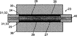
Fig. 2 shows the film that has the catalyst-coated of framework according to the present invention.
The film 23 of the catalyst-coated of describing in Fig. 2 preferably prepares by the inventive method.It comprises and has ionomer layer 26 or 27 and two semi-finished product 24,25 of male or female catalyst layer 28 or 29 separately.Anode catalyst layer 28 flushes with first ionomer layer 26 and finishes and cathode catalyst layer 29 flushes with second ionomer layer 27 and finishes.First semi-finished product 24 and second semi-finished product 25 are of different sizes so that have half-finished projecting edge 30 by the film 23 of the catalyst-coated of two semi-finished product 24,25 preparation.Framework 31 is fixed on the half-finished projecting edge 30.
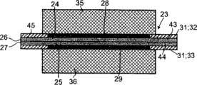
Fig. 3 shows the film that has the another kind of catalyst-coated of the framework of being made by half framework of two different sizes according to the present invention.
The film of the catalyst-coated of describing in Fig. 3 is to a great extent corresponding to the film of describing among Fig. 2, and difference is that it and the framework 31 of half framework 32,33 that comprises two different sizes link.The first half frameworks have bigger size and around the first less semi-finished product 24, and the second half frameworks 33 have less size and around the second bigger semi-finished product 25.The external edge 34 of half framework 32,33 flushes.
Fig. 4 shows the film of the another kind of catalyst-coated of the gas diffusion layers that has framework and different size according to the present invention.
The structure of the film 23 of the catalyst-coated of describing in Fig. 4 is to a great extent corresponding to the film of describing among Fig. 3; Especially, framework 31 is made of two and half frameworks 32,33.The gas diffusion layers 35,36 of two different sizes links with the film of catalyst-coated 23.Herein, each gas diffusion layers 35 or 36 area are corresponding to the area of corresponding semi-finished product 24 or 25.Thereby first gas diffusion layers 35 flush with anode catalyst layer 28 and finish, and second gas diffusion layers 36 flushes with cathode catalyst layer 29 and finishes.
Fig. 5 shows the film of the another kind of catalyst-coated of the gas diffusion layers that has framework and same size according to the present invention.
The structure of the film 23 of the catalyst-coated of describing in Fig. 5 is to a great extent corresponding to the film of describing among Fig. 3; Especially, framework 31 is made of two and half frameworks 32,33.The gas diffusion layers 35,36 of two same sizes links with the film of catalyst-coated 23.Herein, in two gas diffusion layers 35,36 area of each corresponding to the area of second semi-finished product 25.Therefore second gas diffusion layers 36 flushes with cathode catalyst layer 29 and finishes.First gas diffusion layers 35 has and protrudes in the edge 37 of (than small size) anode catalyst layer 28.Thereby the edge 37 of gas diffusion layers and the first half frameworks 32 are overlapped.
Fig. 6 shows the film that has the another kind of catalyst-coated of framework, gas diffusion layers and liner according to the present invention.
Describe among Fig. 6 according to the structure of the film 23 of the catalyst-coated with framework 31 and gas diffusion layers 35,36 of the present invention to a great extent corresponding to the structure of the embodiment of describing among Fig. 5.In addition, liner 38,39 be installed under every kind of situation between the first half frameworks 32 and first gas diffusion layers 35 and the second half frameworks 33 and second gas diffusion layers 36 between transition region.
Fig. 7 shows the film of the another kind of catalyst-coated in two catalyst layers of the whole area that has the ionomer layer of imposing on according to the present invention and intermediate layer.
The film 23 of the catalyst-coated of describing among Fig. 7 comprises and has ionomer layer 26 or 27 and execute thereon the male or female catalyst layer 28 of whole area or two semi-finished product 24,25 of 29 separately.Anode catalyst layer 28 flushes with first ionomer layer 26 and finishes, and cathode catalyst layer 29 flushes with second ionomer layer 27 and finishes.First semi-finished product 24 and second semi-finished product 25 have area identical.Between first ionomer layer 26 and second ionomer layer 27, have than any the more large-area intermediate coat 40 in two semi-finished product 24,25.The result is, intermediate coat 40 protrude in catalyst-coated film 23 two semi-finished product 24,25 the limit and form the edge 41 of intermediate coat.
Fig. 8 shows the film that has the another kind of catalyst-coated of the framework of being made by two and half frameworks according to the present invention.
The film 23 of the catalyst-coated of describing among Fig. 8 is to a great extent corresponding to the film of describing among Fig. 7; Difference is that it and the framework 31 that comprises half framework 32,33 of two same sizes are connected.Two and half frameworks 32,33 are fixed on the edge 41 of intermediate coat.The external edge 34 of half framework 32,33 flushes.
Fig. 9 shows the film that has the another kind of catalyst-coated of framework and gas diffusion layers according to the present invention.
The structure of the film 23 of the catalyst-coated of describing among Fig. 9 is to a great extent corresponding to the structure among Fig. 8, and wherein two gas diffusion layers 35,36 link with the film 23 of catalyst-coated.The size of gas diffusion layers 35,36 is greater than the size of two semi-finished product 24,25, and part is overlapping with half framework 32,33.Two gas diffusion layers 35,36 have same size.
Figure 10 shows the film that has the another kind of catalyst-coated of intermediate coat, framework, gas diffusion layers and liner according to the present invention.
Structure the structure to a great extent of the film 23 of the catalyst-coated of in Figure 10, describing of the present invention with intermediate coat 40, framework 31 and gas diffusion layers 35,36 corresponding to the embodiment of describing among Fig. 9.In addition, liner 38,39 be installed under every kind of situation between the first half frameworks 32 and first gas diffusion layers 35 and the second half frameworks 33 and second gas diffusion layers 36 between transition region.
Figure 11 shows the film of the another kind of catalyst-coated of the catalyst layer that has the catalyst layer that imposes on whole area according to the present invention and impose on the part area.
The film 23 of the catalyst-coated of describing among Figure 11 comprises and has ionomer layer 26 or 27 and two semi-finished product 24,25 of male or female catalyst layer 28 or 29 separately.Cathode catalyst layer 29 imposes on the whole area of second ionomer layer 27 and flushes with it and finish.Anode catalyst layer 28 imposes on the part area of first ionomer layer 26, so that the edge of ionomer layer 42 protrudes in anode catalyst layer 28.Because two catalyst layers 28,29 have area identical, therefore the edge 42 of an ionomer layer also protrudes in the film 23 of catalyst-coated.
Figure 12 shows the film that has the another kind of catalyst-coated of a part of framework according to the present invention.
The film of the catalyst-coated of describing among Figure 12 is to a great extent corresponding to the film of describing among Figure 11, and difference is that it links to each other with a slice framework 31.Framework 31 is fixed on the projecting edge 42 of an ionomer layer.It flushes with the edge 42 of ionomer layer and finishes.
Figure 13 shows the film of the another kind of catalyst-coated that has the anode that imposes on the part area and cathode layer according to the present invention.
The film 23 of the catalyst-coated of describing among Figure 13 comprises and has ionomer layer 26 or 27 and two semi-finished product 24,25 of male or female catalyst layer 28 or 29 separately.Two catalyst layers 28,29 only impose on the part area of ionomer layer 26,27, so that the edge 43,44 of each ionomer layer 26,27 protrudes in catalyst layer 28,29.In the film 23 of catalyst-coated, two edges of this of ionomer layer 43,44 form the film edge 45 of the catalyst layer 28,29 that protrudes in two same sizes.
Figure 14 shows the film that has the another kind of catalyst-coated of the framework of being made by two and half frameworks that are fixed to film edge according to the present invention.
The film of the catalyst-coated of describing among Figure 14 has to a great extent the structure corresponding to Figure 13, and its middle frame 31 is fixed on the edge 45 of film of extra existence.This framework 31 comprises that edge 45 two same sizes and film flushes and half framework 32,33 that finishes.In the film 23 that the preparation catalyst according to the invention applies, two and half frameworks 32,33 can be at two semi-finished product 24,25 link with the edge 45 of film after having linked, and perhaps each half framework 32,33 can be in this ionomer layer 26, after 27 carriers that imposed on separately and at each catalyst layer 28,29 impose on ionomer layer 26,27 links with ionomer layer 26,27 before.
In rolling method according to the present invention, wherein catalyst layer is being applied framework with after preparing each semi-finished product, impose on the ionomer layer, can for example at first impose on each carrier thin film for ionomer layer, then framework film and ionomer layer are linked, as applying catalyst ink or printed catalyst ink, each catalyst layer is imposed on the ionomer layer in the window that is formed by the framework film then by blade coating.
Figure 15 shows the film of the another kind of catalyst-coated with framework and gas diffusion layers.
The film 23 of the catalyst-coated of describing among Figure 15 has to a great extent the structure corresponding to Figure 14, and wherein two gas diffusion layers 35,36 link with the film 23 of catalyst-coated extraly.Gas diffusion layers 35,36 has than the big area of catalyst layer 28,29 and with two and half frameworks 32,33 overlaps.
Figure 16 shows the film that has the another kind of catalyst-coated of framework, gas diffusion layers and liner according to the present invention.
The structure of the embodiment that the structure of the film of describing among Figure 16 23 with framework 31 and gas diffusion layers 35,36 catalyst-coated is described corresponding to Figure 15 to a great extent.In addition, liner 38,39 be installed under every kind of situation between the first half frameworks 32 and first gas diffusion layers 35 and the second half frameworks 33 and second gas diffusion layers 36 between transition region.
Figure 17 shows the film that has the another kind of catalyst-coated of gas diffusion layers and liner according to the present invention.
The film 23 of the catalyst-coated of describing among Figure 17 also has two gas diffusion layers 35,36 that protrude in catalyst layer 28,29 that is linked and the projecting edge 46,47 that forms gas diffusion layers separately except the structure that Figure 13 describes.These edges 46,47 of gas diffusion layers with in addition further the edge of outstanding film 45 have liner 28,39 around them.Liner 38,39 flushes with film edge 45 and finishes.
Figure 18 demonstration has the catalyst layer that imposes on the part area and is fixed on the film of the another kind of catalyst-coated of two frameworks between the ionomer layer according to the present invention.
The film 23 of the catalyst-coated of describing among Figure 18 comprises and has ionomer layer 26 or 27 and two semi-finished product 24,25 of male or female catalyst layer 28 or 29 separately.Two ionomer layer 26,27 are only used catalyst layer 28,29 coated portion areas, protrude in the edge 43 of first ionomer layer of catalyst layer 28,29 and the edge 44 of second ionomer layer so that they form the edge.Part central frame 48 is fixed between the edge 43,44 of these two ionomer layer.Central frame 48 protrudes in two edges 43,44 of ionomer layer.This preferred embodiment of the film 23 of catalyst-coated of the present invention can not mixed so that framework has to thicken.
Figure 19 shows the film that has the another kind of catalyst-coated of framework and gas diffusion layers according to the present invention.
The film 23 of the catalyst-coated of describing among Figure 19 has to a great extent the structure corresponding to the film of Figure 18, but additionally has the gas diffusion layers 35,36 that two films 23 with catalyst-coated link.The edge 43,43 of each in the gas diffusion layers 35,36 and two ionomer layer flushes and finishes.
Figure 20 shows the film that has the another kind of catalyst-coated of central frame, gas diffusion layers and liner according to the present invention.
The structure of the embodiment that the structure of the film 23 of the catalyst-coated of describing among Figure 20 that has central frame 48 and gas diffusion layers 35,36 according to the present invention is described corresponding to Figure 19 to a great extent.In addition, liner 38,39 is in the transition region that is installed under every kind of situation between central frame 48 and the gas diffusion layers 35,36.
Figure 21 shows the current-voltage curve according to the first embodiment of the invention and first Comparative Examples.
Voltage U (mV of unit) is mapped on Y-axis, current density I/A (unit: mA/cm
2) on X-axis, map.Continuous lines is corresponding to according to embodiments of the invention, and dotted line is corresponding to Comparative Examples.Embodiment is discussed in more detail below.
Model is the GK1065-049d (blend film that comprises sPEEK and Ultrason E; Not hydration) has the NMP of residual solvent content>22% and two films that dry layer thickness is 22 μ m, wherein each is positioned on the thick PET film that provides as carrier of 100 μ m, with comprise contain have an appointment 50% the catalyst ink that loads on the Pt catalyst on the carbon black and
 Ionomer solution (EW11005%, Sigma Aldrich) sprays with preparation in a side has about 0.15mg/cm respectively
2And 0.4mg/cm
2The semi-finished product of the anode-side of Pt load and the semi-finished product of cathode side.Remove carrier.Going up between two cardboard sheet with the roller temperature at thin layer press (Ibico IL 12HR) 2 half is that 120 ℃ and speed are adjusted into 2 and link to form the films of catalyst-coated.Subsequently compound is used 1N H
2SO
4Handled 2 hours at 80 ℃, wash fully in room temperature with deionized water then.(SGL Carbon, 21BC) suppress 10 minutes under the pressure of 90 ℃ and 20kN is 32.5cm to form active area together for the film of the catalyst-coated of Huo Deing and two gas diffusion layers in this way
2Membrane electrode assembly (MEA).The MEA of Huo Deing is at 25cm in this way
2Test pool (for example Electro Chem) at 75 ℃, 1 crust, under 100% relative humidity, use H
2(λ=1.5) and O
2Operate (λ=2).The alternating-current resistance that records this system by the impedance spectrometry is 2.8m Ω.
Ionomer solution (EW11005%, Sigma Aldrich) sprays with preparation in a side has about 0.15mg/cm respectively
2And 0.4mg/cm
2The semi-finished product of the anode-side of Pt load and the semi-finished product of cathode side.Remove carrier.Going up between two cardboard sheet with the roller temperature at thin layer press (Ibico IL 12HR) 2 half is that 120 ℃ and speed are adjusted into 2 and link to form the films of catalyst-coated.Subsequently compound is used 1N H
2SO
4Handled 2 hours at 80 ℃, wash fully in room temperature with deionized water then.(SGL Carbon, 21BC) suppress 10 minutes under the pressure of 90 ℃ and 20kN is 32.5cm to form active area together for the film of the catalyst-coated of Huo Deing and two gas diffusion layers in this way
2Membrane electrode assembly (MEA).The MEA of Huo Deing is at 25cm in this way
2Test pool (for example Electro Chem) at 75 ℃, 1 crust, under 100% relative humidity, use H
2(λ=1.5) and O
2Operate (λ=2).The alternating-current resistance that records this system by the impedance spectrometry is 2.8m Ω.
Comparative Examples 1
Model is the GK1065-049d (blend film that comprises sPEEK and Ultrason E; H at 1M
2SO
4In, 80 ℃ of hydrations 2 hours) dry layer thickness is the film of the NMP of 43 μ m and residual solvent content<0.5%, with comprise contain have an appointment 50% the catalyst ink that loads on the Pt catalyst on the carbon black and
 Ionomer solution (EW11005%, Sigma Aldrich) sprays with preparation Pt load in both sides be 0.15mg/cm
2Anode-side and Pt load be 0.4mg/cm
2Cathode side.(SGL Carbon, 21BC) suppressing 10 minutes together under the pressure of 90 ℃ and 20kN is 32.5cm to form active area for the film of the catalyst-coated of Huo Deing and two gas diffusion layers in this way
2Membrane electrode assembly (MEA).The MEA of Huo Deing is at 25cm in this way
2Test pool (for example Electro Chem) at 75 ℃, 1 crust, under 100% relative humidity, use H
2(λ=1.5) and O
2Operate (λ=2).Current-voltage curve is shown among Figure 21 equally, specifically with dashed line form.The alternating-current resistance that records this system by the impedance spectrometry is 3m Ω.
Ionomer solution (EW11005%, Sigma Aldrich) sprays with preparation Pt load in both sides be 0.15mg/cm
2Anode-side and Pt load be 0.4mg/cm
2Cathode side.(SGL Carbon, 21BC) suppressing 10 minutes together under the pressure of 90 ℃ and 20kN is 32.5cm to form active area for the film of the catalyst-coated of Huo Deing and two gas diffusion layers in this way
2Membrane electrode assembly (MEA).The MEA of Huo Deing is at 25cm in this way
2Test pool (for example Electro Chem) at 75 ℃, 1 crust, under 100% relative humidity, use H
2(λ=1.5) and O
2Operate (λ=2).Current-voltage curve is shown among Figure 21 equally, specifically with dashed line form.The alternating-current resistance that records this system by the impedance spectrometry is 3m Ω.
Figure 22 shows the current-voltage curve according to the second embodiment of the invention and second Comparative Examples.
Voltage U (mV of unit) is mapped on Y-axis, current density I/A (unit: mA/cm
2) on X-axis, map.Continuous lines is corresponding to according to embodiments of the invention, and dotted line is corresponding to Comparative Examples.Embodiment is discussed in more detail below.
Model is the GK1130-051 (blend film that comprises sPEEK and Ultrason E; Not hydration) NMP and the dry layer thickness with residual solvent content>22% is the film of 35 μ m, contains have an appointment 70% the catalyst ink and the Nafion that load on the Pt catalyst on the carbon black with comprising
TMIonomer solution (EW110010%, Sigma Aldrich) sprays with preparation Pt load in a side and is about 2mg/cm
2The semi-finished product of cathode side.
The film of same model sprays with preparation PtRu load in a side and is about 3mg/cm with comprising the catalyst ink that contains 80% the catalyst that loads on the PtRu on the carbon black of having an appointment and sPEEK ionomer solution
2The semi-finished product of anode-side.
Semi-finished product upward are adjusted into 1 with 130 ℃ of roller Wen Weiyue and speed at thin layer press (Ibico IL 12HR) between 2 PET films link to form CCM.Subsequently with compound 1NHNO
3Handled 2 hours at 60 ℃, wash fully in room temperature with deionized water then.The dry CCM that obtains in this way and to be combined in pool area with 2 gas diffusion layers arranged side by side be 25cm
2Test pool under 70 ℃ and 1 crust, use 3.2% methanol solution and dry air (λ=3) to operate.The alternating-current resistance that records this system by the impedance spectrometry is 12.2m Ω.
Comparative Examples 2
Model is the GK1065-53 (blend film that comprises sPEEK and Ultrason E; H at 1M
2SO
4In, 80 ℃ of hydrations 2 hours) dry layer thickness is the film of the NMP of 61 μ m and residual solvent content<0.5%, contains have an appointment 70% the catalyst ink and the Nafion that load on the Pt catalyst on the carbon black with comprising
TMIt is 2mg/cm that ionomer solution (EW110010%, Sigma Aldrich) sprays with preparation Pt load
2Cathode side, contain have an appointment 80% the catalyst ink that loads on the PtRu catalyst on the carbon black and sPEEK ionomer solution to spray with preparation PtRu load be 3mg/cm with comprising
2Anode-side.
The film of the dry catalyst-coated that obtains in this way and with 2 gas diffusion layers combinations arranged side by side, be 25cm at pool area
2Test pool under 70 ℃ and 1 crust, use 3.2% methanol solution and dry air (λ=3) to operate.Current-voltage curve is shown in (dotted line) among Figure 22 equally.The alternating-current resistance that records this system by the impedance spectrometry is 10.6m Ω.
List of numerals
1 first roller
2 first semi-finished product
3 first carriers
4 first ionomer layer
5 anode catalyst layers
6 second rollers
7 second semi-finished product
8 Second supports
9 second ionomer layer
10 cathode catalyst layers
The film of 11 catalyst-coated
12 expansion directions
13 roll up direction
14 first idler pulleies
15 second idler pulleies
16 ground floor pressure rollers
17 second layer pressure rollers
18 roller directions
19 film roll
20 load thin films
The film that 21 supported catalysts apply
22 storage rollers
The film of 23 catalyst-coated
24 first semi-finished product
25 second semi-finished product
26 first ionomer layer
27 second ionomer layer
28 anode catalyst layers
29 cathode catalyst layers
30 half-finished projecting edges
31 frameworks
32 the first half frameworks
33 the second half frameworks
34 external edge
35 first gas diffusion layers
36 second gas diffusion layers
The edge of 37 gas diffusion layers
38 first liners
39 second liners
40 intermediate coats
The edge of 41 intermediate coats
The edge of 42 ionomer layer
The edge of 43 first ionomer layer
The edge of 44 second ionomer layer
The edge of 45 films
The edge of 46 first gas diffusion layers
The edge of 47 second gas diffusion layers
48 central frames
Claims (18)
1. method for preparing the film of the catalyst-coated that is used for electrochemical device, it comprises:
A) prepare first semi-finished product by following step:
-first ionomer layer is imposed on first carrier,
-use first catalyst ink that anode catalyst layer is imposed on first ionomer layer,
-dry anode catalyst layer,
B) prepare second semi-finished product by following step:
-second ionomer layer is imposed on second carrier,
-use second catalyst ink that cathode catalyst layer is imposed on second ionomer layer,
-dried cathode catalyst layer and
C) remove first and second carriers respectively from first and second ionomer layer, and by first ionomer layer and second ionomer layer are linked and first semi-finished product and second semi-finished product are linked.
2. according to the process of claim 1 wherein that the one deck at least in first and second ionomer layer is carrying out step C) comprise the solvent of 0.5-35% before.
3. according to the method for claim 1 or 2, wherein described first semi-finished product directly or via intermediate coat are linked with second semi-finished product indirectly.
4. according to each method among the claim 1-3, wherein said first semi-finished product have different areas with second semi-finished product so that half-finished outstanding edge still keeps link the film that forms catalyst-coated at two semi-finished product after.
5. according to each method among the claim 1-4, the projecting edge of the projecting edge of its middle frame and half-finished projecting edge, intermediate coat, the projecting edge of ionomer layer or film links.
6. according to the method for claim 5, wherein said framework links after first semi-finished product and the binding of second semi-finished product or after applying first or second ionomer layer and before applying the male or female catalyst layer.
7. according to each method among the claim 1-6, wherein the film with described catalyst-coated is connected with the framework that comprises half framework of two different sizes.
8. according to each method among the claim 1-7, wherein said middle boxes is installed between the edge of two ionomer layer that protrude in anode and cathode catalyst layer.
9. according to each method among the claim 1-8, wherein one deck at least in anode and the cathode catalyst layer and gas diffusion layers are linked.
10. according to the method for claim 9, wherein said anode catalyst layer is connected with first gas diffusion layers, cathode catalyst layer is connected with second gas diffusion layers, so that first gas diffusion layers and anode catalyst layer and second gas diffusion layers and cathode catalyst layer flush separately, perhaps so that the one deck at least in first and second gas diffusion layers has the edge that protrudes in the male or female catalyst layer.
11. according to the method for claim 10, the edge of wherein said gas diffusion layers is overlapping to small part and framework.
12. according to each method among the claim 1-11, the film of wherein said catalyst-coated links with framework and each side is connected with gas diffusion layers, liner is installed on the film or at least one transition region between framework and the gas diffusion layers of catalyst-coated.
13. according to each method among the claim 1-12, wherein at least one is comprised be selected from following additives additional layer at step C) impose on before between two semi-finished product: solvent, polyelectrolyte solution, polyelectrolyte dispersion, filler and catalyst.
14. according to each method among the claim 1-13, wherein at step C) in described first semi-finished product are connected to second semi-finished product, wherein first and second semi-finished product have the ionomer layer of sulfonation in various degree.
15. according to each method among the claim 1-14, wherein the one deck at least in the ionomer layer comprises at least a following additional component that is selected from: blend components, strengthen fabric, micropore load thin film and filler.
16. a method for preparing the membrane electrode assembly that is used for electrochemical device comprises:
I) first ionomer layer is imposed on the carrier, use catalyst ink that catalyst layer is imposed on first ionomer layer, dried catalyst layer is also removed carrier,
Ii) second ionomer layer is imposed on the gas-diffusion electrode and
Iii) first ionomer layer and gas-diffusion electrode are linked the formation membrane electrode assembly.
17. be used for the film (11,23) of the catalyst-coated of electrochemical device, it comprises at least two semi-finished product connected to each other (2,7; 24,25), promptly comprise and anode catalyst layer (5,28) first ionomer layer (4 of Lian Jieing, 26) first semi-finished product (2,24) and comprise and cathode catalyst layer (10,29) second ionomer layer (9 of Lian Jieing, 27) second semi-finished product (7,25), its middle frame (31) links with the projecting edge (40) of half-finished projecting edge (30), intermediate coat, the projecting edge (42) of ionomer layer or the projecting edge (45) of film, perhaps is installed between the edge (43,44) of two ionomer layer as central frame (48).
18. fuel cell that comprises the film of at least a catalyst-coated according to claim 17.
Applications Claiming Priority (2)
| Application Number | Priority Date | Filing Date | Title |
|---|---|---|---|
| DE102005038612A DE102005038612A1 (en) | 2005-08-16 | 2005-08-16 | Process for the preparation of double-sided catalyst coated membranes |
| DE102005038612.1 | 2005-08-16 |
Publications (1)
| Publication Number | Publication Date |
|---|---|
| CN101288192A true CN101288192A (en) | 2008-10-15 |
Family
ID=36972975
Family Applications (1)
| Application Number | Title | Priority Date | Filing Date |
|---|---|---|---|
| CNA2006800383464A Pending CN101288192A (en) | 2005-08-16 | 2006-08-15 | Method for producing membranes coated with a catalyst on both sides |
Country Status (9)
| Country | Link |
|---|---|
| US (1) | US20100291462A1 (en) |
| EP (1) | EP1917693A1 (en) |
| JP (1) | JP2009505364A (en) |
| KR (1) | KR20080034982A (en) |
| CN (1) | CN101288192A (en) |
| CA (1) | CA2618192A1 (en) |
| DE (1) | DE102005038612A1 (en) |
| NO (1) | NO20080530L (en) |
| WO (1) | WO2007020258A1 (en) |
Cited By (7)
| Publication number | Priority date | Publication date | Assignee | Title |
|---|---|---|---|---|
| CN106256039A (en) * | 2014-03-24 | 2016-12-21 | 庄信万丰燃料电池有限公司 | Method |
| CN107275648A (en) * | 2016-04-06 | 2017-10-20 | 格林纳瑞缇有限公司 | For the method and apparatus for the film for preparing catalyst coating |
| CN109923242A (en) * | 2016-11-04 | 2019-06-21 | 株式会社日本多宁 | Solid macromolecule membrane electrode |
| CN110114512A (en) * | 2016-12-22 | 2019-08-09 | 庄信万丰燃料电池有限公司 | The film of catalyst coating with laminate structures |
| CN111224111A (en) * | 2018-11-23 | 2020-06-02 | 中国科学院大连化学物理研究所 | Batch production device and method for fuel cell membrane electrode |
| CN112913060A (en) * | 2018-06-12 | 2021-06-04 | 海德罗莱特有限公司 | Alkaline membrane fuel cell assembly including a membrane and method of making the same |
| CN114597460A (en) * | 2022-01-17 | 2022-06-07 | 北京化工大学 | Preparation of integrated membrane electrode for reducing interface impedance |
Families Citing this family (26)
| Publication number | Priority date | Publication date | Assignee | Title |
|---|---|---|---|---|
| US7785435B2 (en) | 2006-02-27 | 2010-08-31 | Gm Global Technology Operations, Inc. | Method of laminating a decal to a carrier film |
| JP5515241B2 (en) * | 2008-06-26 | 2014-06-11 | 大日本印刷株式会社 | FUEL CELL ELECTRODE, METHOD FOR PRODUCING FUEL CELL ELECTRODE, ELECTRODE-ELECTROLYTE MEMBRANE LAMINATE, FUEL CELL CELL, AND FUEL CELL |
| DE102009031305A1 (en) | 2009-06-30 | 2011-01-05 | Uhde Gmbh | Catalyst-coated support, process for its preparation, a reactor equipped therewith and its use |
| EP2580799B1 (en) | 2010-06-08 | 2017-03-08 | Rensselaer Polytechnic Institute | Method for the production of an electrochemical cell |
| JP5389768B2 (en) * | 2010-11-02 | 2014-01-15 | 株式会社日立製作所 | POLYMER ELECTROLYTE MEMBRANE, MEMBRANE ELECTRODE ASSEMBLY USING SAME, AND SOLID POLYMER FUEL CELL |
| DE102010063254A1 (en) * | 2010-12-16 | 2012-06-21 | FuMA-Tech Gesellschaft für funktionelle Membranen und Anlagentechnologie mbH | Membrane electrode assembly with two cover layers |
| DE102011105072B3 (en) * | 2011-06-21 | 2012-11-15 | Daimler Ag | Retention device for fuel cell for converting chemical energy into electrical power, has membrane arranged between frame elements in form-fit manner, and sealing element arranged on outer portion of one frame element with larger frame width |
| DE102011105071B4 (en) * | 2011-06-21 | 2014-08-07 | Daimler Ag | Method for producing a holding device with a membrane of a membrane-electrode unit for a fuel cell |
| US8709199B2 (en) * | 2011-09-13 | 2014-04-29 | GM Global Technology Operations LLC | Method of preparing a water vapor transfer membrane |
| ES2676201T3 (en) | 2011-09-15 | 2018-07-17 | Siemens Aktiengesellschaft | Procedure for dry production of a membrane-electrode unit, membrane-electrode unit, as well as roller distribution |
| US9490497B2 (en) | 2012-04-27 | 2016-11-08 | Panasonic Intellectual Property Management Co., Ltd. | Solid polymer electrolyte type fuel cell, and electrolyte membrane-electrode-frame assembly |
| DE102012017142B4 (en) | 2012-08-30 | 2018-06-21 | Mann + Hummel Gmbh | Humidifying device, in particular for a fuel cell |
| JPWO2014087957A1 (en) * | 2012-12-03 | 2017-01-05 | Jsr株式会社 | Electrolyte membrane assembly, membrane-electrode assembly, fuel cell, water electrolysis cell and water electrolysis device |
| DE102012224284A1 (en) * | 2012-12-21 | 2014-06-26 | Heraeus Precious Metals Gmbh & Co. Kg | Thin metal membrane with carrier |
| DE102014205035A1 (en) * | 2014-03-18 | 2015-09-24 | Volkswagen Ag | Method for producing a membrane-electrode assembly, membrane-electrode assembly, fuel cell and motor vehicle with fuel cell |
| CN106463746B (en) | 2014-03-24 | 2019-06-04 | 庄信万丰燃料电池有限公司 | Film seal assembly |
| GB201408953D0 (en) * | 2014-05-20 | 2014-07-02 | Johnson Matthey Fuel Cells Ltd | Membrane electrode assembly |
| US9705146B2 (en) * | 2014-12-29 | 2017-07-11 | National Cheng Kung University | Method of fabricating proton-conducting electrolytic membrane |
| JP6515830B2 (en) * | 2016-01-28 | 2019-05-22 | トヨタ自動車株式会社 | Method of manufacturing membrane electrode assembly |
| EP3504747B1 (en) * | 2016-08-25 | 2023-11-01 | Proton Energy Systems, Inc. | Membrane electrode assembly and method of making the same |
| KR102359584B1 (en) * | 2017-06-19 | 2022-02-07 | 현대자동차주식회사 | MEA for fuel cell and Manufacture method of MEA |
| DE102018220418A1 (en) | 2018-11-28 | 2020-05-28 | Robert Bosch Gmbh | Method for producing a membrane electrode arrangement |
| CN111063924B (en) * | 2019-12-27 | 2022-10-14 | 先进储能材料国家工程研究中心有限责任公司 | Transition layer slurry for membrane electrode, preparation method of transition layer slurry, membrane electrode and preparation method of membrane electrode |
| DE102020102709A1 (en) | 2020-02-04 | 2021-08-05 | Audi Aktiengesellschaft | Method for producing a membrane electrode assembly, membrane electrode assembly and fuel cell |
| DE102021209025A1 (en) * | 2021-08-17 | 2023-02-23 | Volkswagen Aktiengesellschaft | Cutting device and method for producing electrode sheets from an electrode foil |
| DE102022202195A1 (en) | 2022-03-03 | 2023-09-07 | Robert Bosch Gesellschaft mit beschränkter Haftung | Electrochemical Cell Unit |
Family Cites Families (9)
| Publication number | Priority date | Publication date | Assignee | Title |
|---|---|---|---|---|
| DE19910773A1 (en) * | 1999-03-11 | 2000-09-28 | Degussa | Process for applying electrode layers to a band-shaped polymer electrolyte membrane for fuel cells |
| US6641862B1 (en) * | 1999-09-24 | 2003-11-04 | Ion Power, Inc. | Preparation of fuel cell electrode assemblies |
| JP2003323898A (en) * | 2002-04-22 | 2003-11-14 | E I Du Pont De Nemours & Co | Processed gas diffusion backing and its use for fuel battery |
| US6933003B2 (en) * | 2002-06-13 | 2005-08-23 | General Motors Corporation | Method of making membrane electrode assemblies |
| DE10315796B4 (en) * | 2003-04-07 | 2009-06-04 | Umicore Ag & Co. Kg | Layer construction for an electrochemical cell, process for its preparation and use thereof |
| US7226689B2 (en) * | 2003-06-20 | 2007-06-05 | Ballard Power Systems Inc. | Method of making a membrane electrode assembly for electrochemical fuel cells |
| EP1492184A1 (en) * | 2003-06-27 | 2004-12-29 | Umicore AG & Co. KG | Process for the manufacture of a polymer electrolyte membrane coated with a catalyst |
| WO2005006480A2 (en) * | 2003-07-14 | 2005-01-20 | Umicore Ag & Co. Kg | Membrane-electrode unit for the electrolysis of water |
| US20050072514A1 (en) * | 2003-10-06 | 2005-04-07 | Yan Susan G. | Method of making membrane electrode assemblies |
-
2005
- 2005-08-16 DE DE102005038612A patent/DE102005038612A1/en not_active Withdrawn
-
2006
- 2006-08-15 JP JP2008526491A patent/JP2009505364A/en not_active Withdrawn
- 2006-08-15 US US12/063,202 patent/US20100291462A1/en not_active Abandoned
- 2006-08-15 CA CA002618192A patent/CA2618192A1/en not_active Abandoned
- 2006-08-15 EP EP06778239A patent/EP1917693A1/en not_active Withdrawn
- 2006-08-15 KR KR1020087005514A patent/KR20080034982A/en not_active Application Discontinuation
- 2006-08-15 CN CNA2006800383464A patent/CN101288192A/en active Pending
- 2006-08-15 WO PCT/EP2006/065310 patent/WO2007020258A1/en active Application Filing
-
2008
- 2008-01-29 NO NO20080530A patent/NO20080530L/en not_active Application Discontinuation
Cited By (13)
| Publication number | Priority date | Publication date | Assignee | Title |
|---|---|---|---|---|
| CN106256039A (en) * | 2014-03-24 | 2016-12-21 | 庄信万丰燃料电池有限公司 | Method |
| CN106256039B (en) * | 2014-03-24 | 2019-06-04 | 庄信万丰燃料电池有限公司 | The method for manufacturing the film seal assembly of enhancing |
| CN107275648A (en) * | 2016-04-06 | 2017-10-20 | 格林纳瑞缇有限公司 | For the method and apparatus for the film for preparing catalyst coating |
| CN107275648B (en) * | 2016-04-06 | 2022-02-18 | 格林纳瑞缇有限公司 | Method and apparatus for preparing catalyst coated membranes |
| CN109923242A (en) * | 2016-11-04 | 2019-06-21 | 株式会社日本多宁 | Solid macromolecule membrane electrode |
| CN109923242B (en) * | 2016-11-04 | 2021-10-29 | 株式会社日本多宁 | Solid polymer membrane electrode |
| CN113529121A (en) * | 2016-12-22 | 2021-10-22 | 庄信万丰燃料电池有限公司 | Catalyst coated membrane with laminated structure |
| CN110114512B (en) * | 2016-12-22 | 2021-08-10 | 庄信万丰燃料电池有限公司 | Catalyst coated membrane with laminated structure |
| CN110114512A (en) * | 2016-12-22 | 2019-08-09 | 庄信万丰燃料电池有限公司 | The film of catalyst coating with laminate structures |
| CN112913060A (en) * | 2018-06-12 | 2021-06-04 | 海德罗莱特有限公司 | Alkaline membrane fuel cell assembly including a membrane and method of making the same |
| CN111224111B (en) * | 2018-11-23 | 2021-04-02 | 中国科学院大连化学物理研究所 | Batch production device and method for fuel cell membrane electrode |
| CN111224111A (en) * | 2018-11-23 | 2020-06-02 | 中国科学院大连化学物理研究所 | Batch production device and method for fuel cell membrane electrode |
| CN114597460A (en) * | 2022-01-17 | 2022-06-07 | 北京化工大学 | Preparation of integrated membrane electrode for reducing interface impedance |
Also Published As
| Publication number | Publication date |
|---|---|
| KR20080034982A (en) | 2008-04-22 |
| NO20080530L (en) | 2008-03-10 |
| EP1917693A1 (en) | 2008-05-07 |
| WO2007020258A1 (en) | 2007-02-22 |
| DE102005038612A1 (en) | 2007-02-22 |
| CA2618192A1 (en) | 2007-02-22 |
| JP2009505364A (en) | 2009-02-05 |
| US20100291462A1 (en) | 2010-11-18 |
Similar Documents
| Publication | Publication Date | Title |
|---|---|---|
| CN101288192A (en) | Method for producing membranes coated with a catalyst on both sides | |
| CA2436101C (en) | Catalyst-coated ionomer membrane with protective film layer and process for its manufacture | |
| EP1387423B1 (en) | Water-based catalyst inks and their use for manufacture of catalyst-coated substrates | |
| US20140315121A1 (en) | Method for the preparation of catalyst-coated membranes method for the preparation of catalyst-coated membranes | |
| JP5113977B2 (en) | Process for producing a catalyst coated membrane and a membrane electrode assembly for a fuel cell | |
| US20170104225A1 (en) | Process of manufacturing a catalyst-coated membrane-seal assembly | |
| US20110097651A1 (en) | Membrane Electrode Assembly (MEA) Fabrication Procedure on Polymer Electrolyte Membrane Fuel Cell | |
| US20110217621A1 (en) | Process to produce catalyst coated membranes for fuel cell applications | |
| US9780399B2 (en) | Electrode assembly with integrated reinforcement layer | |
| US20120183878A1 (en) | Manufacturing Method Of Electrode Catalyst Layer, Electrode Catalyst Layer, Membrane Electrode Assembly And Fuel Cell | |
| KR101312971B1 (en) | Hydrocarbon based polyelectrolyte separation membrane surface-treated with fluorinated ionomer, membrane electrode assembly, and fuel cell | |
| KR102110843B1 (en) | Process | |
| Scott | Membrane electrode assemblies for polymer electrolyte membrane fuel cells | |
| Lobato et al. | Application of Sterion® membrane as a polymer electrolyte for DMFCs | |
| KR100792136B1 (en) | Method of preparing catalyst coated membrane using mask | |
| KR101189675B1 (en) | Catalyst-coated membrane with integrated sealing material and membrane-electrode assembly produced therefrom | |
| EP3664209B1 (en) | Manufacturing method for membrane electrode assembly, and stacked body | |
| JP5405783B2 (en) | Fuel cell catalyst layer, fuel cell catalyst layer transfer sheet, fuel cell gas diffusion electrode, fuel cell membrane electrode assembly, and fuel cell | |
| KR100792137B1 (en) | Method of preparing catalyst coated membrane comprising protecting film layer for fuel cell | |
| KR20160083713A (en) | Polymer electrolyte membrane for fuel cell comprising hydrogen and oxygen eliminating layer, membrane electrode assembly comprising the same and fuel cell comprising the same | |
| EP4326925A2 (en) | Catalyst coated membranes for water electrolysers | |
| KR20080045420A (en) | Method of producing membrane-electrode assembly | |
| JP2007250471A (en) | Manufacturing method of fuel cell | |
| JP2007157429A (en) | Manufacturing method of fuel cell |
Legal Events
| Date | Code | Title | Description |
|---|---|---|---|
| C06 | Publication | ||
| PB01 | Publication | ||
| C10 | Entry into substantive examination | ||
| SE01 | Entry into force of request for substantive examination | ||
| C02 | Deemed withdrawal of patent application after publication (patent law 2001) | ||
| WD01 | Invention patent application deemed withdrawn after publication |
Open date: 20081015 |