CN101272438A - Document illuminator with LED-driven phosphor - Google Patents
Document illuminator with LED-driven phosphor Download PDFInfo
- Publication number
- CN101272438A CN101272438A CNA2008100854800A CN200810085480A CN101272438A CN 101272438 A CN101272438 A CN 101272438A CN A2008100854800 A CNA2008100854800 A CN A2008100854800A CN 200810085480 A CN200810085480 A CN 200810085480A CN 101272438 A CN101272438 A CN 101272438A
- Authority
- CN
- China
- Prior art keywords
- light
- optical element
- document
- led
- luminaire
- Prior art date
- Legal status (The legal status is an assumption and is not a legal conclusion. Google has not performed a legal analysis and makes no representation as to the accuracy of the status listed.)
- Pending
Links
Images


Classifications
-
- H—ELECTRICITY
- H04—ELECTRIC COMMUNICATION TECHNIQUE
- H04N—PICTORIAL COMMUNICATION, e.g. TELEVISION
- H04N1/00—Scanning, transmission or reproduction of documents or the like, e.g. facsimile transmission; Details thereof
- H04N1/024—Details of scanning heads ; Means for illuminating the original
- H04N1/028—Details of scanning heads ; Means for illuminating the original for picture information pick-up
- H04N1/02815—Means for illuminating the original, not specific to a particular type of pick-up head
-
- H—ELECTRICITY
- H04—ELECTRIC COMMUNICATION TECHNIQUE
- H04N—PICTORIAL COMMUNICATION, e.g. TELEVISION
- H04N1/00—Scanning, transmission or reproduction of documents or the like, e.g. facsimile transmission; Details thereof
- H04N1/04—Scanning arrangements, i.e. arrangements for the displacement of active reading or reproducing elements relative to the original or reproducing medium, or vice versa
-
- H—ELECTRICITY
- H04—ELECTRIC COMMUNICATION TECHNIQUE
- H04N—PICTORIAL COMMUNICATION, e.g. TELEVISION
- H04N1/00—Scanning, transmission or reproduction of documents or the like, e.g. facsimile transmission; Details thereof
- H04N1/024—Details of scanning heads ; Means for illuminating the original
- H04N1/028—Details of scanning heads ; Means for illuminating the original for picture information pick-up
- H04N1/02815—Means for illuminating the original, not specific to a particular type of pick-up head
- H04N1/0282—Using a single or a few point light sources, e.g. a laser diode
- H04N1/02825—Using a single or a few point light sources, e.g. a laser diode in combination with at least one reflector which is fixed in relation to the light source
-
- H—ELECTRICITY
- H04—ELECTRIC COMMUNICATION TECHNIQUE
- H04N—PICTORIAL COMMUNICATION, e.g. TELEVISION
- H04N1/00—Scanning, transmission or reproduction of documents or the like, e.g. facsimile transmission; Details thereof
- H04N1/024—Details of scanning heads ; Means for illuminating the original
- H04N1/028—Details of scanning heads ; Means for illuminating the original for picture information pick-up
- H04N1/02815—Means for illuminating the original, not specific to a particular type of pick-up head
- H04N1/0282—Using a single or a few point light sources, e.g. a laser diode
- H04N1/02835—Using a single or a few point light sources, e.g. a laser diode in combination with a light guide, e.g. optical fibre, glass plate
-
- H—ELECTRICITY
- H04—ELECTRIC COMMUNICATION TECHNIQUE
- H04N—PICTORIAL COMMUNICATION, e.g. TELEVISION
- H04N1/00—Scanning, transmission or reproduction of documents or the like, e.g. facsimile transmission; Details thereof
- H04N1/024—Details of scanning heads ; Means for illuminating the original
- H04N1/028—Details of scanning heads ; Means for illuminating the original for picture information pick-up
- H04N1/02815—Means for illuminating the original, not specific to a particular type of pick-up head
- H04N1/02885—Means for compensating spatially uneven illumination, e.g. an aperture arrangement
- H04N1/0289—Light diffusing elements, e.g. plates or filters
-
- H—ELECTRICITY
- H04—ELECTRIC COMMUNICATION TECHNIQUE
- H04N—PICTORIAL COMMUNICATION, e.g. TELEVISION
- H04N1/00—Scanning, transmission or reproduction of documents or the like, e.g. facsimile transmission; Details thereof
- H04N1/024—Details of scanning heads ; Means for illuminating the original
- H04N1/028—Details of scanning heads ; Means for illuminating the original for picture information pick-up
- H04N1/02815—Means for illuminating the original, not specific to a particular type of pick-up head
- H04N1/02895—Additional elements in the illumination means or cooperating with the illumination means, e.g. filters
-
- H—ELECTRICITY
- H04—ELECTRIC COMMUNICATION TECHNIQUE
- H04N—PICTORIAL COMMUNICATION, e.g. TELEVISION
- H04N1/00—Scanning, transmission or reproduction of documents or the like, e.g. facsimile transmission; Details thereof
- H04N1/024—Details of scanning heads ; Means for illuminating the original
- H04N1/028—Details of scanning heads ; Means for illuminating the original for picture information pick-up
- H04N1/03—Details of scanning heads ; Means for illuminating the original for picture information pick-up with photodetectors arranged in a substantially linear array
- H04N1/031—Details of scanning heads ; Means for illuminating the original for picture information pick-up with photodetectors arranged in a substantially linear array the photodetectors having a one-to-one and optically positive correspondence with the scanned picture elements, e.g. linear contact sensors
- H04N1/0318—Integral pick-up heads, i.e. self-contained heads whose basic elements are a light-source, a lens array and a photodetector array which are supported by a single-piece frame
-
- H—ELECTRICITY
- H04—ELECTRIC COMMUNICATION TECHNIQUE
- H04N—PICTORIAL COMMUNICATION, e.g. TELEVISION
- H04N2201/00—Indexing scheme relating to scanning, transmission or reproduction of documents or the like, and to details thereof
- H04N2201/0077—Types of the still picture apparatus
- H04N2201/0081—Image reader
Abstract
A document illuminator with a LED driving phosphor is disclosed. A scanning apparatus includes an illuminator for illuminating a portion of a document to be scanned. The illuminator includes at least one light source and an optical element positioned to redirect light emitted by the light source. A phosphor material is disposed to intercept at least a portion of the light redirected by the optical element. A photosensitive device is positioned to receive light reflected from the document for recording an image of the document.
Description
Technical field
Being used to of the present invention relates to that the digital record in digital scanner, facsimile machine and digital copier for example uses the throw light on lighting apparatus of hard copy file.Particularly, the present invention relates to a kind of luminaire that is arranged at the fluorescent material between light source and the hard copy file that comprises, this luminaire provides more uniform illumination.
Background technology
In the office equipment such as digital copier and facsimile machine, the original hardcopy file uses the equipment that can be described as " scanner " usually to be registered as numerical data.In the typical scan instrument, illumination file paper (document sheet), and from the light of file paper reflection by light-sensitive unit record, to convert DID to such as CCD (charge coupled device) or CMOS (complementary metal oxide semiconductors (CMOS)) array (being also referred to as contact image sensor (CIS)).When paper moves through file processor or light-sensitive unit relative to the platen of placing this document paper thereon (platen) when moving, the continuous fillet of illumination this document paper.These fillets of document image are become the complete image of original document to represent by combination of software subsequently.
The CIS scan bar (scan bar) that is used for file scanning uses the various light sources that comprise light-emitting diode (LED) and cold-cathode fluorescence lamp (CCFL).The CCFL illumination can be directly used in monochromatic scanning, and perhaps by using the transducer that has RGB (red, green and blue) filter arrays above pixel, the CCFL white illumination can be used for the scanning colour image.Although the CCFL illumination is tending towards very evenly and provide white light, this lamp to adopt high voltage usually and have high power consumption.LED base luminaire typically adopts translucent element, and this translucent element utilizes the light of internal reflection guiding from LED, to form from the exit facet of this element substantially parallel ray towards file.Such scan bar often uses the single led monochromatic scanning that is used for, and perhaps uses red, blue and green ternary LED (for example, based on InGaAlP, InGaN and GaP) catches coloured image.For chromoscan, RGB LED is opened one at a time continuously, thereby catches the independent image of three width of cloth, and every width of cloth image makes up complete color scanning image from the independent image of this three width of cloth subsequently with every kind of color illumination.This luminaire comprises prism, is used for from each illumination broadening and stride across the bar of file as far as possible equably of these three LED (RGB).
The existing challenge of luminaire that is designed for scanner is, for example, provides along the file fillet promptly along the even illumination of short scan direction.Some these LED base luminaires use the lenticular back side that notch is arranged on away from the luminaire prism side of file destination, this back side is caught the light of advancing along the length of luminaire downwards and along reflecting this light with the approximately perpendicular direction of major axis of scan bar.The light of reflection subsequently from the front from this luminaire prism outgoing, and illumination target paper surface.Other scan bar is gone up overleaf and is used the white paint pattern, and it compares the change refractive index with the optical surface that is exposed to air, to reach similar effect.Notch or lacquer pattern have the pattern that changes along the length of light pipe prism downwards, the illumination that illumination of locating in the hope of equilrium prism near-end (the most close LED) and prism far-end (away from LED) are located, otherwise the illumination in the prism proximal end will be the brightest.For example, in notch design, the notch of far-end more deeply and bigger, the notch of proximal end is more shallow.In this design, the less notch of proximal end (illumination will be the brightest) redirects (redirect) less general ambient light along the file direction, and the larger slot mouth of far-end to be intended to catch more general ambient light far away from the LED source to compensate it.Yet these LED luminaire light pipe prisms still present significant illumination unevenness.Particularly, downwards or with a kind of color during with the comparison of another kind of color, these LED luminaire light pipe prisms are not to be tending towards providing even illumination along scan bar length.Secondary reflection or other scattered beam from the prism far-end are tending towards being difficult to realizing strict illumination uniformly.In addition, this design is tending towards inhomogeneous between direct reflection and diffused lighting farmland (domain).Last thisly inhomogeneously especially can cause problem, because be tending towards causing uneven increase in another farmland in order to reduce inhomogeneous and any correction that use in the farmland.Usually can't once differently calibrate two farmlands, and some paper surface is the combination (for example, bright pebble grain surface, wherein glossy surface part is in the reflection of direct reflection farmland, and remainder is illuminated on the diffusion farmland) on direct reflection and diffused lighting surface.
The irregular meeting of illumination level in the illuminated zone causes the defective of view data, and these defectives may can't be proofreaied and correct in software fully, particularly for the situation such as the discrete light source of LED.
Summary of the invention
According to an aspect of exemplary embodiment, a kind of scanning device comprises the luminaire of a part of file to be scanned that is used to throw light on.This luminaire comprises: at least one light source; Optical element is set to redirect the light by this light emitted; And fluorescent material, at least a portion that is set to tackle the light that is redirected by this optical element.Light-sensitive unit is set to receive the light from this document reflection, is used to write down the image of this document.
In this equipment, this optical element can comprise this fluorescent material.
The layer that this optical element can comprise the base part that is formed by light transmissive material and comprise this fluorescent material.This base part can comprise at least one reflecting element, is used to redirect light from this light source towards this document.This at least one reflecting element can be included in a plurality of notches at the back side of this optical element.This at least one reflecting element can be included in a plurality of reflection lacquer spots (paint patch) at the back side of this optical element.This base part can and comprise between the layer of fluorophor between this light source.
This at least one light source can comprise light-emitting diode.
This fluorescent material can convert the light from this light source to the light of the wavelength combinations of the light of different wave length or expectation.Can be by the light of this optical element emission (comprise the light of this fluorescent material conversion and from the non-switched light of this LED) near white light.
This optical element definable plane of incidence and exit facet, this exit facet is substantially perpendicular to this plane of incidence, and wherein this light source is set to contiguous this plane of incidence, and this fluorescent material is set to contiguous this exit facet.
This equipment can further comprise the platen that is used to support this document, and this platen is set to the exit facet of contiguous this optical element usually.
This optical element and this at least one light source can be supported on the movable carriage.
This fluorescent material can be arranged on the back side of this optical element.
According on the other hand, a kind of luminaire comprises optical element, this optical element definition plane of incidence and opposing backside surface and exit facet.This exit facet is substantially perpendicular to this plane of incidence.This back side comprises and is used to redirect the light that receives from this plane of incidence a plurality of reflecting elements towards the front.Granular materials is arranged between this reflecting element and this front, is used for diffusion incident light thereon.At least one light source is set to contiguous this plane of incidence.
In this luminaire, this granular materials can comprise at least a fluorophor.
A kind of scanning device can comprise this luminaire and can further comprise light-sensitive unit that this light-sensitive unit is set to receive the image that is used to write down this document from the light of this document reflection.
This scanning device can be monochromatic scanning device.
According on the other hand, a kind of method of scanning document comprises that exciting light source is with emission light; Transmit this light with the optical element through over-illumination this document, this transmission comprises this light of transmission with through optical element layer, and this layer comprises granular materials, and the situation of this granular materials is more uneven for the light ratio of this document thus.
This transmission can further comprise uses a plurality of reflecting elements to redirect this radiative at least a portion towards this layer.
This transmission can further comprise uses this fluorescent material to convert at least a portion light to wavelength longer light.
Description of drawings
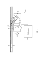
Fig. 1 is the simplification front view according to the file scanner of exemplary embodiment;
Fig. 2 is the enlarged diagram of the luminaire of Fig. 1;
Fig. 3 is the enlarged diagram of a part of the luminaire of Fig. 2, and the direction of light in the prism is described;
Fig. 4 is the enlarged diagram of a part of the luminaire of Fig. 3, and the direction of the light of adhesive fluorescence body particle is described; And
Fig. 5 is the enlarged diagram of another embodiment of a part that is applicable to the luminaire of Fig. 1 file scanner.
Embodiment
The aspect of this exemplary embodiment relates to a kind of luminaire, and relates to a kind of file scanning device or " scanner " that comprises this luminaire.This exemplary embodiment also relates to a kind of physical file scan method that is used to produce scan image.File to be scanned can comprise paper or other flexible base, board, and one or more image setting to be scanned thereon.This scanner can form for example part of the imaging device of autonomous scanners, photocopier, facsimile machine or multi-function device, wherein in these devices, scan image is colored on paper and/or is stored as digital form and for example is used for showing, handling or transmission with digital form.This exemplary scan device can be applicable to file scanner, multi-function printer, currency scanner, identity badge scanner etc.
Generally comprise diffusion and specular components from the light of luminaire emission.Specular components generally reflects from hard copy file according to the angle identical with the angle of working as the even relatively time shot file in surface.In some cases, from the part of the light of light source can by minute surface reflex in the imaging sensor and add the signal output of imaging sensor to.In conventional scanner, the quantity that arrives the specular light of transducer can change along the quantity of short scan direction with respect to diffused lighting.
Aspect this exemplary embodiment, fluorescent material is combined in the luminaire.This fluorescent material diffusion is by the light such as the light emitted of one or more light-emitting diodes or laser diode (the two all is called LED at this).Therefore this exemplary illuminator has more uniform illumination along the short scan direction, causes the improvement of picture quality.Particularly, reduce, and the quantity that arrives the diffused light of transducer increases as the quantity of the specular light of the arrival imaging sensor of the part of whole light.
With reference to figure 1, comprise platen 10 according to the file scanner of this exemplary embodiment, can be arranged on this platen 10 such as the scanning target of file paper 12 and be used for carrying out record by it.Alternatively, the file processor (not shown) is associated with platen 10, and this document processor is sequentially from multipage original document paper feeding.

Illustrate best as Fig. 2, luminaire 18 comprises that form is the optical element 30 of light pipe prism, and such as at least one discrete light source 32 (having 2 in the illustrated embodiment) of one or more light-emitting diodes or laser diode (the two all is called LED at this).Light source 32 is set to light is directed in the optical element 30.In the described herein exemplary embodiment, have a more than light source 32, these light sources are encouraged simultaneously; But in other embodiments, can consider sequential energisation LED.Also can consider other discrete light source, for example the optical fiber photoconduction.Optical element 30 can be made by the light transmissive material of any optical quality, for example glass, quartz, Merlon, acrylic acid or other plastic material.
Because internal reflection in prism, shown optical element 30 will be from the photoconduction of light source 32 on the imaging region of platen.In Fig. 1 and 2, schematically illustrate light, so that the general direction that light is propagated to be shown.In one embodiment, scanner comprises two luminaires 18, and these two luminaires 18 are from different directions with the substantially the same zonule of photoconduction to the file of waiting to throw light on.
As shown in Figure 2, optical element 30 has its longest dimension L along promptly vertical with the scan bar 16 direct of travels direction of short scan direction.In the embodiment of Fig. 2 to 4, all LED are set to an end face 40 of the longest dimension of contiguous this optical element.If little point source of light 32 is the form of little LED, then each light source 32 can be arranged in the dimple shape spill in the plane of incidence 40.Alternatively, LED can be arranged at other position, and uses right angle reflector illuminated from the end.Optical element 30 comprises the back side 44 and front or exit facet 46, and this back side 44 constitutes away from the surface of file 12, and light is directed on the file by this front or exit facet 46.This back side and front generally can be arranged in parallel to each other, as shown.In other embodiments, the front is can be with the back side angled and/or be crooked, rather than the plane.
A plurality of reflecting elements 48 are 44 layouts along the back side.Shown reflecting element 48 is included in the protrusion that defines notch therebetween, but also can consider to provide other reflecting element, the reflection that for example separates lacquer spot.The number of the notch/lacquer spot in the scan bar 16 for example can be about 20 to 500.Some are advanced downwards and are radiated at the notch 48 at the prism back side 44 along the length of prism 30 from the light of LED 32.Notch reflects light towards scanning target 12 as a series of small reflectors.The light of LED32 emission is therefore by the front 46 of notch 48 reflections towards optical element.Protrusion/notch is shown near the LED 32 less, and towards away from end face 49 increased in size of the prism 30 of LED.This helps to make at least in part the distribution equilibrium of the light that strides across the prism length L.In another embodiment, notch can have same size and shape along length L.
As shown in Figure 1, optical element 30 can make emission light to spend the average angle α shot file of for example about 30 to 60 degree between 0 and 90 with respect to the paper surface angulation.Although in the embodiment shown, front 46 is positioned at usually and the parallel plane plane of paper surface, but in alternative, and front 46 can be slightly and the light angulation." inclination " in the face 46 can depart from file plane 5 to 15 degree, for example about 10 degree.
Shown in Fig. 2 to 4, fluorescent material 50 is arranged between LED 32 and the file 12.In one embodiment, fluorescent material is attached in the layer 52 of definition optical element front 46.Layer 52 can extend jointly along the length L of prism and the base part 54 of optical element 30, these base part 54 definition or supporting reflex elements 48.Generally speaking, the material that comprises fluorophor that is used to form layer 52 by use applies or clad substrates part 54, and layer 52 and base part 54 rigidity are adhered to mutually to form single integral body, makes layer 52 be used as the cap of preformed base part 54.Layer 52 can be formed by the light transmissive material identical with base part 54, but also can use different materials.
As shown in Figure 1, layer 52 and base part 54 can all have along the cross section profile of the length L of optical element or substantially the same on the whole page width degree of optical element at least (for example, except the width of notch 48).
In the embodiment shown in Fig. 3 to 5, base part 54 is at light source 32 and comprise between the layer 52 of fluorophor, makes that light is most of before irradiation fluorescent material 50 to be reflected by the back side 44.Fluorescent material 50 can be the form of fine particle, and these fine particles are dispersed throughout layer 52 relatively equably, with interception at least a portion from the light of LED emission.This fluorescent material is used for diffusion and incides light on it, compares with the similar scan bar that does not have fluorescent material to form thus, reduces light inhomogeneous of shot file.
Prism 30 can be sealed at least in part and cover in 56 (for example, the carriages).In the embodiment shown, lid 56 is around all faces of the prism except exit facet 46.Lid 56 can be formed by the material that opaque material or refractive index are different from prism, makes light in this prism inside internal reflection.
Fig. 3 explanation by notch scattering LED light 60 with produce main towards the front 46 the light 62 of advancing along a plurality of directions, and by the further scattered beam 62 of fluorescent material, to produce by the more light diffuse scattering shown in the light 64.Fig. 4 illustrates how each fluorophor particle 50 plays contribution to diffusion of light.To understand, fluorophor particle can be launched and comprises towards the back side 44 the light along all directions.As shown in Figure 1, this diffusion emission causes more most light to be reflected into from file 12 being diffused light (light that is reflected with all angles), shown in light 70, and more the light of small part is reflected into and is the specular light (light that is arranged in parallel with the excellent lens of scan bar, make this light from target bounce-back and be tending towards forming the light of dazzling of glossy surface, this can make the image blurring of this glossy surface below conversely), shown in light 72.
Compare with the light diffusion that can obtain by improvement prism surface texture, the emitting performance of fluorophor particle 50 is tending towards providing more uniform light diffusion.Particularly, fluorophor particle helps to encourage its neighbour's fluorophor particle, and this energy is shared more largo and broadening light more equably, and this is because light energy is propagated the desired illumination loss of superficial makings that illumination loss through fluorophor is lower than absorbing light more and has loss.
In one embodiment, fluorescent material 50 is used for being converted to the light of different wave length by at least a portion of the light of LED 32 emission.For example, when the narrower wavelength of LED emission light time of blueness and/or ultraviolet range for example, fluorescent material can convert at least a portion of this light to the light of other wavelength, makes the light of emission distribute more equably and spreads all over visible-range.This more equally distributed light often is called " white light ".To understand, " white light " comprises various shadows (shade), daylight, cold white, warm white etc. for example, and wherein spectrum is different from slightly and really evenly distributes.All these are considered as approximate white light.Can select other wavelength combinations to be used for some and use, this depends on the spectral composition that scans target.Can obtain all this flexibilities by having the mixture of the different fluorophor of light emission characteristics separately in the wavelength field.
In putting into practice embodiment, the width w (Fig. 2) of front 46 is in about scope of 10 to 15mm, height h (Fig. 4) between the face 44 and 46 can be for about 10 to 20mm, and the length L of optical element 30 (Fig. 3) can be near the width of file to be scanned, and for example about 25 to 30cm.The thickness t of luminescent coating 52 (Fig. 4) can be for below about 2mm, for example at least 1 micron.
Known in this area, scanner can comprise the memory of the digital picture that is used for memory scanning.In conjunction with or the image color applicator that is linked to scanner can comprise such as the image of marking engine and color component that this image color component and used such as the colouring agent of ink or toner that the image of being stored is painted on the substrate such as paper.In conjunction with or the facsimile machine that is linked to scanner can comprise treatment element, this treatment element is used for the digital picture being stored by the form output that telephone wire, cable link or other suitable wired or wireless link transmit.
Can use the fluorophor be applicable to exemplary embodiment disclosed herein or fluorophor combination and produce white lights by variety of way from LED 32.When more than a kind of fluorophor was used as fluorescent material 50, these fluorophor can be the forms of mixture.Alternatively, fluorophor can be arranged to multilayer form discretely, and these multilayers are formed layer 52 together.
In one embodiment, use single fluorophor, for example cerium doped yttrium aluminum garnet Y
3Al
5O
2: Ce
3+(" YAG:Ce ") or cerium doping terbium aluminium garnet Tb
3Al
5O
12: Ce
3+(" TAG:Ce ").Encourage this fluorophor such as blue light, make its emission gold-tinted from InGaN LED emission.This gold-tinted and the blue light combination of being launched by LED are near white light.In conventional fluorescent body representation, the expression of composition main body before the branch, and the expression of composition activator behind the branch.
In another embodiment, fluorescent material comprises two kinds of fluorophor.For example, first fluorophor will convert green glow to from the UV/blue of LED, and second fluorophor converts UV/blue to ruddiness.This system is for example in U.S. Patent No. 6,252, discloses in 254.The fluorophor of suitable green light comprises YBO
3: Ce
3+, Tb
3+, BaMgAl
10O
17: Eu
2+, Mn
2+, with at least a fluorophor that glows Y for example
2O
2S:Eu
3+, Bi
3+, YVO
4: Eu
3+, Bi
3+, SrS:Eu
2+, SrY
2S
4: Eu
2+Deng combination.The output of combination is near white light.
In other embodiments, first fluorophor converts the LED blue light to orange-colored light, and second fluorophor converts blue light to green-yellow light.The output of combination is near white light.This fluorophor combination for example discloses in patent disclosure No.20060231849.Other pair phosphor system discloses in patent disclosure No.20060113553.In this system, first fluorophor can be the Eu that sends out orange-colored light
2+, Mn
2+Doping strontium pyrophosphate (Sr
0.8Eu
0.1Mn
0.1)
2P
2O
7, second fluorophor can be the Eu of green glow of turning blue
2+(Sr mixes
0.90-0.99Eu
0.01-0.1)
4Al
14O
25
In another embodiment, fluorophor comprises three kinds of (or more) fluorophor, for example the red, green and blue inorganic phosphor each one of at least.Any red, green and blue inorganic phosphor can use at this.Red fluorophor can comprise and being selected from by (Sr, Ca, Ba, Mg) P
2O
7: Eu
2+, Mn
2+, CaLa
2S
4: Ce
3+, SrY
2S
4: Eu
2+, (Ca, Sr) S:Eu
2+, SrS:Eu
2+, Y
2O
3: Eu
3+, Bi
3+, YVO
4: Eu
3+, Bi
3+, Y
2O
2S:Eu
3+, Bi
3+, Y
2O
2S:Eu
3+At least a fluorescent material of selecting in the group of forming.Green luminophore can comprise and being selected from by YBO
3: Ce
3, Tb
3, BaMgAl
10O
17: Eu
2+, Mn
2+, (Sr, Ca, Ba) (Al, Ga)
2S
4: Eu
2+, ZnS:Cu, Al, Ca
8Mg (SiO
4)
4Cl
2: Eu
2+, Mn
2+, Ba
2SiO
4: Eu
2+, (Ba, Sr)
2SiO
4: Eu
2+, Ba
2(Mg, Zn) Si
2O
7: Eu
2+, (Ba, Sr) Al
2O
4: Eu
2+And Sr
2Si
3O
8.2SrCl
2: Eu
2+At least a fluorescent material of selecting in the group of forming.Blue fluorophor can comprise be selected from by (Sr, Mg, Ca)
10(PO
4)
6Cl
2: Eu
2+, BaMgAl
10O
17: Eu
2+And BaMg
2Al
16O
27: Eu
2+At least a fluorescent material of selecting in the group of forming.
Be suitable for fluorescent material 50 to produce other suitable phosphorescence powder formulation near the light of white light at United States Patent (USP) 5,813,753,6,252,254,6,294,800,6,621,211,6,635,987,6,685,852,6,853,131,6,809,471,6,936,857,7,038,370,7,075,225,7,112,921,7, disclose in 157,745 and 7,157,746.In addition, although in this exemplary embodiment, the output of luminaire 18 is described as near white light, is white light and can have any suitable wavelengths scope but should understand that this light need not.
In one embodiment, from the light wavelength of light source 32 at 360nm to the scope of about 490nm.Light source 32 can have the emission peak in about 420 to 470nm scopes.Gallium nitride (GaN) based illuminating device can be used as this light supply apparatus.Indium gallium (GaI) and the basic LED of indium gallium nitride (GaInN) and other LED also can use.
Situation for the scan bar 16 that is applicable to monochrome (for example black and white) scanning, luminaire 18 can adopt single led or a plurality of LED 32 and make up with fluorescent material 50, wherein this LED 32 is all luminous at the blueness and/or the narrow wave band in the ultraviolet range of for example spectrum, and fluorescent material 50 change at least a portion from the light of LED to produce well light near the wideer spectrum of white light.In one aspect, all light sources in the luminaire all are same types, for example launch UV/blue, and therefore luminous so that monochromatic (for example, blueness) light to be provided in same wavelength ranges.For example, all the light emitted peak wavelengths in the luminaire are less than the light of about 470nm.Fluorescent material will partly be launched light and convert more long wavelength's light to, make emission light also comprise the light in 490 to 700nm wave-length coverages (the green red sector territory of arriving of electromagnetic spectrum) except the light of blue spectrum (400 to 490nm).
No matter the needs that depend on application are general file scanning, currency scanning, or other purpose, and the emission color of the glow color of phosphor preparation or LED can be chosen as has the particular color tone that produces the expectation contrast level in scan image.For example, if the light of transducer 22 more acceptant specific wavelengths, then luminaire 18 can be adjusted into and produce the light of facilitating this wavelength.
Be applicable to the situation of chromoscan, described similar luminaire 18 in the time of can using with monochrome application for scan bar 16.According to the attainable similar fashion of scan bar of using the CCFL luminaire, luminaire 18 can use with filtered image sensor element, to limit the color of each pixel detection.For example, filter is used to allow red, green and blue light to arrive transducer 22 successively by order.
Alternatively, the luminaire 18 that is used for chromoscan can comprise peak wavelength in zones of different, for example respectively at three luminous LED of the red, green and blue zone of electromagnetic spectrum.Three LED are by sequential energisation.Optionally the fluorescent material in response to three kinds of wavelength provides red, green and blue emission light in proper order.
The advantage of these some aspects of exemplary embodiment is luminaire 18, and owing to the luminescent coating 52 as diffuser, this luminaire 18 provides the illumination that obtains than traditional C IS system to throw light on more uniformly.Each fluorophor particle 50 can be used as the lighting point light source, and it can collect the illumination from LED 32 of being scattered by transparent light guide pipe prism 30, and will scatter again on omnirange ground basically from the light of a large amount of point-source of lights subsequently.This has increased the uniformity that light strides across scan bar 16, has reduced the effect that minute surface is dazzled light simultaneously, particularly for the situation of smooth file.
Therefore this exemplary illuminator can be launched with like the CCFL lamp ﹠ lantern and thrown light on, and only needs the electrical power of a LED 32.Extra LED or superbright LED also can be used for brighter illumination.This exemplary illuminator 18 has that the CCFL lamp provides very evenly, fully scatters and the abundant attribute of the light of diffusion.Yet, compare with the CCFL luminaire, these exemplary illuminator 18 common costs of manufacture are lower, non-friable, not cracky, need much lower power and only need the electricity of LED light source 32 to drive requirement.
Exemplary manufacture method comprises, by making the base part 54 that is used for light pipe prism 30 by clear acrylic or other suitable polymers material injection molding.After basic luminaire shape moulding, (object-oriented file) front is coated by identical base material, and powder white phosphor filler has added this clear plastic base material to.LED 32 can be assembled in the dimple that defines in base part 54 or be installed on the chip at scan bar top, to light shine element 30.When the light stimulus of being scattered by the transparent part by the light pipe prism 54, front layer 52 with fluorophor filler 50 of emission white light is launched the light of very diffusion, this light is mainly the color by the phosphor preparation emission, but a little color is from the color of LED 32.
Fig. 5 illustrates another embodiment of luminaire, and except described, this luminaire can be configured to the luminaire of Fig. 1 to 4 similarly.In this embodiment, the layer that comprises fluorescent material 50 52 is arranged on the back side 44 of prism.Itself compare with notch 48, this fluorophor is diffused light to a greater degree.In certain embodiments, notch 48 can omit.In this embodiment, the back side 44 can be roughened.
Claims (3)
1. scanning device comprises:
Be used to the to throw light on luminaire of a part of file to be scanned, this luminaire comprises:
At least one light source;
Optical element is set to redirect the light by this light emitted; And
Fluorescent material, at least a portion that is set to tackle the light that is redirected by this optical element, and
Light-sensitive unit is set to receive the light from this document reflection, is used to write down the image of this document.
2. luminaire comprises:
Optical element, this optical element definition plane of incidence and opposing backside surface and exit facet, this exit facet is substantially perpendicular to this plane of incidence, this back side comprises and is used to redirect the light that receives from this plane of incidence a plurality of reflecting elements towards the front that granular materials is arranged at and is used for diffusion incident light thereon between this reflecting element and this front; And
Be set at least one light source of contiguous this plane of incidence.
3. the method for a scanning document comprises:
Exciting light source is with emission light;
Transmit this light with the optical element through over-illumination this document, this transmission comprises this light of transmission with through optical element layer, and this layer comprises granular materials, and the situation of this granular materials is more uneven for the light ratio of this document thus.
Applications Claiming Priority (2)
| Application Number | Priority Date | Filing Date | Title |
|---|---|---|---|
| US11/725860 | 2007-03-20 | ||
| US11/725,860 US7864381B2 (en) | 2007-03-20 | 2007-03-20 | Document illuminator with LED-driven phosphor |
Publications (1)
| Publication Number | Publication Date |
|---|---|
| CN101272438A true CN101272438A (en) | 2008-09-24 |
Family
ID=39591969
Family Applications (1)
| Application Number | Title | Priority Date | Filing Date |
|---|---|---|---|
| CNA2008100854800A Pending CN101272438A (en) | 2007-03-20 | 2008-03-19 | Document illuminator with LED-driven phosphor |
Country Status (5)
| Country | Link |
|---|---|
| US (1) | US7864381B2 (en) |
| EP (1) | EP1973325B1 (en) |
| JP (1) | JP4781377B2 (en) |
| KR (1) | KR20080085761A (en) |
| CN (1) | CN101272438A (en) |
Cited By (4)
| Publication number | Priority date | Publication date | Assignee | Title |
|---|---|---|---|---|
| CN104170363A (en) * | 2012-03-14 | 2014-11-26 | 三菱电机株式会社 | Light source device |
| CN107525042A (en) * | 2016-06-22 | 2017-12-29 | Lg伊诺特有限公司 | Phosphor plate and the lighting device including the phosphor plate |
| CN109118990A (en) * | 2017-06-22 | 2019-01-01 | 施乐公司 | The system and method for the image specific illumination of image for being printed onto optical waveguide |
| CN112042613A (en) * | 2020-09-11 | 2020-12-08 | 杭州汉徽光电科技有限公司 | Method for pest control by blue light and converted light thereof |
Families Citing this family (15)
| Publication number | Priority date | Publication date | Assignee | Title |
|---|---|---|---|---|
| KR101279034B1 (en) * | 2007-07-11 | 2013-07-02 | 삼성전자주식회사 | Scanner module and image scanning apparatus |
| JP5572557B2 (en) * | 2008-02-06 | 2014-08-13 | コンテックス・エー/エス | Photometric measurement and correction in optical scanners |
| US8780206B2 (en) * | 2008-11-25 | 2014-07-15 | De La Rue North America Inc. | Sequenced illumination |
| US8265346B2 (en) | 2008-11-25 | 2012-09-11 | De La Rue North America Inc. | Determining document fitness using sequenced illumination |
| JP5336880B2 (en) | 2009-02-24 | 2013-11-06 | 日東光学株式会社 | Light emitting device |
| JP2010204539A (en) * | 2009-03-05 | 2010-09-16 | Ricoh Co Ltd | Original lighting device, image reading apparatus and image forming apparatus |
| US8094323B2 (en) | 2009-06-26 | 2012-01-10 | Mitutoyo Corporation | Displacement encoder including phosphor illumination source |
| US8749767B2 (en) * | 2009-09-02 | 2014-06-10 | De La Rue North America Inc. | Systems and methods for detecting tape on a document |
| US8433124B2 (en) * | 2010-01-07 | 2013-04-30 | De La Rue North America Inc. | Systems and methods for detecting an optically variable material |
| US8509492B2 (en) * | 2010-01-07 | 2013-08-13 | De La Rue North America Inc. | Detection of color shifting elements using sequenced illumination |
| US20110176181A1 (en) * | 2010-01-18 | 2011-07-21 | Mark Walter Fagan | Multi-Item Scanning on a Vertically Oriented Scanner |
| JP6072002B2 (en) * | 2011-04-18 | 2017-02-01 | マリミルス オーワイ | Lighting stripe and lighting stripe system |
| US9053596B2 (en) | 2012-07-31 | 2015-06-09 | De La Rue North America Inc. | Systems and methods for spectral authentication of a feature of a document |
| JP5841587B2 (en) * | 2013-12-25 | 2016-01-13 | 株式会社Pfu | Imaging system |
| EP3551986A4 (en) | 2016-12-09 | 2020-08-05 | FormFactor, Inc. | Led light source probe card technology for testing cmos image scan devices |
Family Cites Families (42)
| Publication number | Priority date | Publication date | Assignee | Title |
|---|---|---|---|---|
| JP3116727B2 (en) | 1994-06-17 | 2000-12-11 | 日亜化学工業株式会社 | Planar light source |
| US6236470B1 (en) * | 1994-12-19 | 2001-05-22 | Xerox Corporation | Reflector and light source registration device for a document illuminator |
| US6316266B1 (en) * | 1995-06-07 | 2001-11-13 | Arizona State University Board Of Regents | Sample presentation apparatus for mass spectrometry |
| JP3133242B2 (en) * | 1995-12-08 | 2001-02-05 | スタンレー電気株式会社 | LED line light source device |
| JPH1097200A (en) | 1997-05-20 | 1998-04-14 | Nichia Chem Ind Ltd | Light source |
| US5813753A (en) | 1997-05-27 | 1998-09-29 | Philips Electronics North America Corporation | UV/blue led-phosphor device with efficient conversion of UV/blues light to visible light |
| US6294800B1 (en) | 1998-02-06 | 2001-09-25 | General Electric Company | Phosphors for white light generation from UV emitting diodes |
| US6252254B1 (en) | 1998-02-06 | 2001-06-26 | General Electric Company | Light emitting device with phosphor composition |
| JPH11317108A (en) * | 1998-05-02 | 1999-11-16 | Canon Inc | Lighting apparatus, and image reading apparatus and image forming apparatus using the lighting apparatus |
| US6469808B1 (en) * | 1998-05-15 | 2002-10-22 | Rohm Co., Ltd. | Image reading apparatus and illuminator used for the same |
| US6333779B1 (en) | 1998-12-24 | 2001-12-25 | Canon Kabushiki Kaisha | Illumination apparatus using light guide |
| JP2000285718A (en) * | 1999-03-29 | 2000-10-13 | Rohm Co Ltd | Surface light source |
| US6354278B1 (en) * | 1999-03-30 | 2002-03-12 | Suzuki Kabushiki Kaisha | Engine of outboard motor |
| JP2001005122A (en) * | 1999-06-18 | 2001-01-12 | Canon Inc | Illumination device and image sensor, original reading device and information processing system having the same |
| JP2001061040A (en) * | 1999-08-20 | 2001-03-06 | Fujitsu Ltd | Illuminator |
| US6565248B2 (en) | 1999-12-17 | 2003-05-20 | Kabushiki Kaisha Toshiba | Light guide, line illumination apparatus, and image acquisition system |
| US6522065B1 (en) | 2000-03-27 | 2003-02-18 | General Electric Company | Single phosphor for creating white light with high luminosity and high CRI in a UV led device |
| US6501100B1 (en) | 2000-05-15 | 2002-12-31 | General Electric Company | White light emitting phosphor blend for LED devices |
| US6621211B1 (en) | 2000-05-15 | 2003-09-16 | General Electric Company | White light emitting phosphor blends for LED devices |
| US6635987B1 (en) | 2000-09-26 | 2003-10-21 | General Electric Company | High power white LED lamp structure using unique phosphor application for LED lighting products |
| JP3392117B2 (en) * | 2000-12-01 | 2003-03-31 | キヤノン株式会社 | Light guide for reader and reader |
| AT410266B (en) | 2000-12-28 | 2003-03-25 | Tridonic Optoelectronics Gmbh | LIGHT SOURCE WITH A LIGHT-EMITTING ELEMENT |
| US6685852B2 (en) | 2001-04-27 | 2004-02-03 | General Electric Company | Phosphor blends for generating white light from near-UV/blue light-emitting devices |
| TWI221385B (en) * | 2001-05-31 | 2004-09-21 | Mustek Systems Inc | CCD type scanner powered by a serial bus |
| JP4672918B2 (en) | 2001-07-12 | 2011-04-20 | キヤノン株式会社 | Image sensor and image reading apparatus |
| US6809471B2 (en) | 2002-06-28 | 2004-10-26 | General Electric Company | Phosphors containing oxides of alkaline-earth and Group-IIIB metals and light sources incorporating the same |
| US20040057082A1 (en) * | 2002-09-24 | 2004-03-25 | Rong-Ji Liu | Method of focusing a selected scanning area for document scanning device |
| JP4087681B2 (en) * | 2002-10-29 | 2008-05-21 | 株式会社日立製作所 | LIGHTING DEVICE AND DISPLAY DEVICE USING THE SAME |
| US6936857B2 (en) | 2003-02-18 | 2005-08-30 | Gelcore, Llc | White light LED device |
| US7400429B2 (en) * | 2003-03-17 | 2008-07-15 | Kabushiki Kaisha Toshiba | Image reading apparatus |
| US7038370B2 (en) | 2003-03-17 | 2006-05-02 | Lumileds Lighting, U.S., Llc | Phosphor converted light emitting device |
| US7157745B2 (en) | 2004-04-09 | 2007-01-02 | Blonder Greg E | Illumination devices comprising white light emitting diodes and diode arrays and method and apparatus for making them |
| CN100409047C (en) * | 2003-06-25 | 2008-08-06 | 日本板硝子株式会社 | Light guide and image reader |
| US7075225B2 (en) | 2003-06-27 | 2006-07-11 | Tajul Arosh Baroky | White light emitting device |
| US7112921B2 (en) | 2003-08-02 | 2006-09-26 | Phosphortech Inc. | Light emitting device having selenium-based fluorescent phosphor |
| JP4638192B2 (en) | 2004-08-26 | 2011-02-23 | 三菱電機株式会社 | Line light source and contact image sensor using the same |
| US7746520B2 (en) * | 2004-11-23 | 2010-06-29 | Xerox Corporation | Document illuminator |
| US7715063B2 (en) * | 2005-03-31 | 2010-05-11 | Xerox Corporation | CVT integrated illuminator |
| US7593143B2 (en) * | 2005-03-31 | 2009-09-22 | Xerox Corporation | Compound curved concentrator based illuminator |
| CN100403563C (en) | 2005-04-18 | 2008-07-16 | 光宝科技股份有限公司 | LED with white light and fluorescent powder concerned and preparation thereof |
| US7755811B2 (en) * | 2005-06-30 | 2010-07-13 | Xerox Corporation | Document illuminator |
| JP2008219405A (en) * | 2007-03-02 | 2008-09-18 | Ushio Inc | Linear light source device |
-
2007
- 2007-03-20 US US11/725,860 patent/US7864381B2/en not_active Expired - Fee Related
-
2008
- 2008-02-25 EP EP08151898.7A patent/EP1973325B1/en not_active Expired - Fee Related
- 2008-03-14 JP JP2008065756A patent/JP4781377B2/en not_active Expired - Fee Related
- 2008-03-19 KR KR1020080025363A patent/KR20080085761A/en not_active Application Discontinuation
- 2008-03-19 CN CNA2008100854800A patent/CN101272438A/en active Pending
Cited By (4)
| Publication number | Priority date | Publication date | Assignee | Title |
|---|---|---|---|---|
| CN104170363A (en) * | 2012-03-14 | 2014-11-26 | 三菱电机株式会社 | Light source device |
| CN107525042A (en) * | 2016-06-22 | 2017-12-29 | Lg伊诺特有限公司 | Phosphor plate and the lighting device including the phosphor plate |
| CN109118990A (en) * | 2017-06-22 | 2019-01-01 | 施乐公司 | The system and method for the image specific illumination of image for being printed onto optical waveguide |
| CN112042613A (en) * | 2020-09-11 | 2020-12-08 | 杭州汉徽光电科技有限公司 | Method for pest control by blue light and converted light thereof |
Also Published As
| Publication number | Publication date |
|---|---|
| JP2008236747A (en) | 2008-10-02 |
| JP4781377B2 (en) | 2011-09-28 |
| US20080231911A1 (en) | 2008-09-25 |
| EP1973325A1 (en) | 2008-09-24 |
| EP1973325B1 (en) | 2015-08-05 |
| US7864381B2 (en) | 2011-01-04 |
| KR20080085761A (en) | 2008-09-24 |
Similar Documents
| Publication | Publication Date | Title |
|---|---|---|
| CN101272438A (en) | Document illuminator with LED-driven phosphor | |
| CN102149966B (en) | Luminaire and illumination system | |
| JP2778659B2 (en) | Light guide, illumination device, and image reading device | |
| CN101539270B (en) | Method for converting light wavelength with emission angle selectivity characteristic | |
| CN102252169B (en) | High-brightness excitation method and light emitting device based on optical wavelength conversion | |
| CN1326111A (en) | Camera image catching device with LED chips | |
| CN1993580B (en) | Light emitting device | |
| CN101573644A (en) | Backlight using high-powered corner LED | |
| JPH10133026A (en) | Illuminator having light transmission body | |
| JP2003100126A (en) | Chromaticity correction by light guide plate | |
| TW201020467A (en) | Colour mixing method for consistent colour quality | |
| TWI461051B (en) | Light-emitting unit, illumination device, image sensor and image reading device using light-emitting unit | |
| JPH11185516A (en) | Image illuminating device and image reading device using same | |
| US6206534B1 (en) | Illumination device for use in image reading applications | |
| JP3139822U (en) | Scanning device | |
| KR20160011102A (en) | Method of manufacturing the light emitting device package | |
| JP2008072398A (en) | Original illuminator, image reader, color original reader and image forming apparatus | |
| JP3766422B2 (en) | Linear light source device and image reading device | |
| CN101390376A (en) | Linear light source device, and image reading device and planar display device using the linear light source device | |
| US9172836B2 (en) | Optical scanner illumination system and method | |
| JP2000324308A (en) | Led linear light source | |
| CN2828866Y (en) | Lens body of light collecting, distributing and mix for fill-in light source of digital camera | |
| CN102238310A (en) | Image scanning device | |
| US7915605B2 (en) | LED packaged structure and applications of LED as light source | |
| CN108506798A (en) | Display device and side entering type light source module group |
Legal Events
| Date | Code | Title | Description |
|---|---|---|---|
| C06 | Publication | ||
| PB01 | Publication | ||
| C10 | Entry into substantive examination | ||
| SE01 | Entry into force of request for substantive examination | ||
| C12 | Rejection of a patent application after its publication | ||
| RJ01 | Rejection of invention patent application after publication |
Application publication date: 20080924 |