CN1012257B - Bioelectric signal measuring apparatus - Google Patents
Bioelectric signal measuring apparatusInfo
- Publication number
- CN1012257B CN1012257B CN86105980A CN86105980A CN1012257B CN 1012257 B CN1012257 B CN 1012257B CN 86105980 A CN86105980 A CN 86105980A CN 86105980 A CN86105980 A CN 86105980A CN 1012257 B CN1012257 B CN 1012257B
- Authority
- CN
- China
- Prior art keywords
- signal
- circuit
- mentioned
- triggering
- output
- Prior art date
- Legal status (The legal status is an assumption and is not a legal conclusion. Google has not performed a legal analysis and makes no representation as to the accuracy of the status listed.)
- Expired
Links
Images

Classifications
-
- A—HUMAN NECESSITIES
- A61—MEDICAL OR VETERINARY SCIENCE; HYGIENE
- A61N—ELECTROTHERAPY; MAGNETOTHERAPY; RADIATION THERAPY; ULTRASOUND THERAPY
- A61N1/00—Electrotherapy; Circuits therefor
- A61N1/18—Applying electric currents by contact electrodes
- A61N1/32—Applying electric currents by contact electrodes alternating or intermittent currents
- A61N1/36—Applying electric currents by contact electrodes alternating or intermittent currents for stimulation
- A61N1/36014—External stimulators, e.g. with patch electrodes
- A61N1/36017—External stimulators, e.g. with patch electrodes with leads or electrodes penetrating the skin
-
- A—HUMAN NECESSITIES
- A61—MEDICAL OR VETERINARY SCIENCE; HYGIENE
- A61H—PHYSICAL THERAPY APPARATUS, e.g. DEVICES FOR LOCATING OR STIMULATING REFLEX POINTS IN THE BODY; ARTIFICIAL RESPIRATION; MASSAGE; BATHING DEVICES FOR SPECIAL THERAPEUTIC OR HYGIENIC PURPOSES OR SPECIFIC PARTS OF THE BODY
- A61H39/00—Devices for locating or stimulating specific reflex points of the body for physical therapy, e.g. acupuncture
- A61H39/02—Devices for locating such points
-
- Y—GENERAL TAGGING OF NEW TECHNOLOGICAL DEVELOPMENTS; GENERAL TAGGING OF CROSS-SECTIONAL TECHNOLOGIES SPANNING OVER SEVERAL SECTIONS OF THE IPC; TECHNICAL SUBJECTS COVERED BY FORMER USPC CROSS-REFERENCE ART COLLECTIONS [XRACs] AND DIGESTS
- Y10—TECHNICAL SUBJECTS COVERED BY FORMER USPC
- Y10S—TECHNICAL SUBJECTS COVERED BY FORMER USPC CROSS-REFERENCE ART COLLECTIONS [XRACs] AND DIGESTS
- Y10S128/00—Surgery
- Y10S128/907—Acupuncture
Abstract
The present invention relates to a bioelectric signal detecting apparatus which comprises a detecting electrode, a reference electrode, an excitation signal generating apparatus, a micro-current amplifying circuit, a signal processing circuit and a signal output apparatus. The detecting apparatus exerts excitation voltage within the range of 0.5 to 3.0V on a reference acupoint of people or an animal body by the reference electrode. Simultaneously, the detecting electrode is used for orderly measuring responding current within the range of 10+(-4) to 10+(-11)A for each acupoint of the body surface by certain pressure. The signal processing circuit is used for processing according to the time characteristic of the responding current for obtaining information for diagnosis and therapeutic effect monitoring.
Description
The present invention relates to a kind of bioelectric signal measuring apparatus, specifically, device of the present invention applies an electric excitation signal by the particular acupoint to human or animal's body surface and measures the response of health to this signal simultaneously, thereby obtain and the distribution information characteristic relevant of bio-electric field in vivo, carry out the diagnosis of disease and the monitoring of health status and therapeutic effect with this with kinestate.
In recent years, china academia circle is based on field theory and information technology, and in conjunction with traditional theory of Chinese medical science, the theory of relevant channel system has particularly been carried out extensive studies and experiment to the important vital signs-life-information of living body biological.Particularly " start " isotopic tracing of phenomenon and channel system to carry out testing and accomplishing tangible results to the qi-gong practitioner by modern testing equipment and means.The inventor makes a large amount of effort to this, relevant achievement in research is published on " Nature Journal " 1980 3 volumes 8 phase 563-566 pages or leaves, is entitled as on " life information science pre-test " and 3 volumes, the 9 phase 681-682 pages or leaves, is entitled as " pericardium channel acupuncture point NaI
125Tracer experiment is explored ", Shanghai science tech publishing house publishes, and " natural science yearbook " 1.34-1.41 page or leaf in 1981; be entitled as " the exploration of vital signs information, simulation and application, " publication of Shanghai science tech publishing house, the content of these articles is incorporated herein by reference.
According to physical viewpoint, rest mass is zero material (various materials) to the material that natural world shows as rest mass with having only energy, two kinds of materials are closely related, any one object that rest mass arranged all corresponding its distinctive natural resonant frequency.Living body biological also shows as has the morphology system that is made of cell, tissue, organ, also have in addition by cell potential, electrocardio, brain electricity and the life information system that various radiation constituted, the two-way interaction coexists as among the living body biological, the channel system of the traditional Chinese medical science, analyze by its characteristics of motion, belong to an organic component of life information system in the human body.No matter the pathological changes of any tissue or organ is functional disorder in the organism, or organic disease, all will change the distribution of life information system field material and the state of motion.Therefore, by the distribution and the characteristics of motion based on the life information system of field material are tested the important information that can obtain to reflect organism health status.
In the tcm clinical practice practice, people notice already, when in the human body during a certain organ generation pathological changes, with often can find some characteristic acupuncture point (as some acupuncture point on brothers or the extremity) on the corresponding body surface meridians of this organ, these acupuncture points show sensitivity and strengthen (for example to press or the sensitivity of acupuncture strengthens) and often treat by acupuncture and moxibustion on these acupuncture points and can receive gratifying curative effect.The meridian theory of this phenomenon and the traditional Chinese medical science meets fully, also often utilizes this phenomenon to come auxiliary diagnosis in clinical practice.But, because the responsive phenomenon in this acupuncture point exists individual variation, and, when clinical practice, it is the same with the meridian point related phenomena with other, mainly be to rely on patient's private prosecution to determine whether it exists, lack the index of objective evaluation and the means of quantitative test, this has just limited its clinical practice greatly.Therefore, utilize modern detection method that acupoint is tested and become a noticeable research field.
In prior art, the existing multiple acupuncture point is detected, device with the information characteristic of obtaining the acupuncture point, these devices are by measuring changes in resistance on the human body Different Acupoint, the variation of current potential, the variation in magnetic field, variation of temperature or acupuncture point are to the variation of the sensitivity of pressure, seek the acupuncture point that has special variation on the health etc. multiple different physical quantity, and disease is diagnosed and treated by the quantitative situation of change of a certain physical quantity that measures on these acupuncture points.
We can see in prior art, a lot of inventors have been found that, when human body generation disease, on some specific acupuncture point of body surface, can measure that skin resistance reduces or current potential increases, design the skin resistance on the multiple measurement particular acupoint or the device of current potential according to this discovery.But, because live body inside distributes according to certain rules and the intensity of the bio-electric field that move is very weak, this electric field under normal circumstances distribution and move and its that difference takes place between the state of pathological changes during the initial stage in vivo is very little.In addition, because the individual variation between live body and the interference of various environmental factorss, these all make the extraction to the detection of bio-electric field and useful information run into a lot of difficulties.When utilizing the eigenvalue of simple receiving type measurement device bio-electric field, when for example measuring the minor variations of acupuncture point current potential with the high sensitivity potentiometer, in order to overcome above-mentioned difficulties, must improve the sensitivity of test set and the interference of capacity of resisting disturbance and the various environmental factorss of strict control, so that obtain valuable testing result.So just make test set and measuring process all too complicated and expensive, and the minor variations of current potential is difficult to distinguish mutually with environmental disturbances on the acupuncture point that is measured.Therefore, to a lot of early stage pathological changes, can't obtain the testing result of statistical significance.At above-mentioned shortcoming, a lot of people have designed the device of determining the specificity acupuncture point by the variation of measuring electrical resistance, and this device is measured the useful information that obtains this acupuncture point by the current value of particular acupoint simultaneously by apply an external drive voltage to live body.This metering system is lower to checkout gear and environment requirement, is convenient to widespread usage, and can reduce the influence of various environmental disturbances factors effectively.But the pressure itself that this stronger driving voltage (being generally 10-20V or higher) and electrode cause on the acupuncture point has constituted the stimulation at acupuncture point and has changed the state that the inner normal bio-electric field of live body distributes and moves artificially.Therefore, measurement interference that live body is caused itself makes and can reflect that much in vivo the useful information of change of illness state can't be detected.
At the problems referred to above that exist in the prior art, the present inventor proposes, the channel system of the traditional Chinese medical science and acupuncture point theory have reflected some particular law that electromagnetic field distributes and moves in the human body, it is an organic ingredient of life information system in the human body, as long as can set up a kind of suitable detection means and resolve environmental disturbances and measurement itself to the problem of this two aspect of interference of electromagnetic field in the human body, the important information of channel system and life information system state be can on different acupuncture points, obtain to reflect, the diagnosis of disease and the curative effect monitoring that therapeutic process is carried out used it for by the electrical quantity that measures live body.
The present invention is a kind of bioelectric signal measuring apparatus according to above-mentioned thought design, this device can apply the electric excitation signal with suitable amplitude to the particular acupoint of human body or animal body surface and measure the response of live body to this signal simultaneously, by the time dependent characteristic curve of the amplitude of response signal is analyzed, can obtain important life-information, and use it for auxiliary diagnosis and instruct treatment.
The present invention is on the basis of extensively experiment, amplitude to pumping signal, waveform, multiple factors such as the mode that applies of signal are selected, make between the bioelectrical signals of this pumping signal and live body self and realized good equilibrium relation, make signal itself can seriously not disturb the distribution and the moving situation of the inner biological electromagnetic field of live body like this, and live body can reflect important life-information to the response of this signal, this information is for the health of difference live body and the situation of disease, and particularly the situation to the difference early lesion has significant statistical significance.
Under pumping signal effect of the present invention, the response of live body is a current signal that intensity is minimum, corresponding with different pathological changes, and this signal can be 10
-4-10
-11Change in the scope of ampere, the micro current amplifier that therefore requires device of the present invention must employing can amplify little electric current, the minimum working current of this amplifier will reach 10
-12Order of amps, during amplifier work, the scope that detects electric current is 10
-4-10
-11Ampere, in order to adapt with this electric current excursion, preferably adopt the logarithm micro current amplifier or by the linear micro current amplifier of index stepping, and this amplifier itself and input thereof contact in the process that detects with human body all should there be good capacity of resisting disturbance.
Under the pumping signal effect of checkout gear of the present invention, little current responsing signal that live body produces shows special time response curve, and the difformity of detected this curve and various disease that live body is suffered from and disease exists special dependency in various degree on different acupuncture points.Therefore, be not only the amplitude of response signal, its time, characteristic shape also had very big diagnostic value, at these characteristics, had adopted signal processing circuit to come this response signal is handled in the device of the present invention.And the segment signal output of this device can demonstrate the characteristic output signal with the time response curvilinear correlation.
When utilizing checkout gear of the present invention to carry out the acupuncture point measurement, particularly when utilizing no wound formula detecting electrode of the present invention to measure, detecting electrode can produce certain influence to the physiological situation of local skin to the different pressures of body surface point, thereby the resistivity of change skin, microcirculation situations etc., this has just affected indirectly measurement precision.In addition, the strong pressure itself excessively on the acupuncture point also can form an intensive outside stimulus, causes the situation of local bio-electric field to change.In order to improve the degree of accuracy of testing result, should be less as far as possible except the pressure that requires the electrode pair acupuncture point, also require the pressure at electrode pair acupuncture point to should be a steady state value, like this, when different people was tested in the different time, can guarantee that the condition of testing is basic identical.In addition, temperature, environmental factorss such as humidity also can exert an influence to skin resistance, so that influence the comparability of measurement result.The present invention has guaranteed that the pressure at electrode pair acupuncture point is a steady state value in the measuring process, and by adjusting this pressure realization ambient temperature and humidity variation has been carried out suitable compensation by the special elastic structure of the adjustable in pressure that design for detecting electrode.
In sum, the problem aspect checkout gear of the present invention has solved two emphatically in the process that the acupuncture point is detected.On the one hand, by strictly limiting the stimulation of pumping signal and detecting electrode to skin point, the interference minimum that the truth to live body built-in field distribution is produced.On the other hand, by signal processing circuit and the signal output apparatus that adopts the very wide micro current amplifier of range and can handle the time response of little electric current, make big the increasing that contain much information that obtains in the testing process, therefore, make device of the present invention can detect a lot of important informations that the various devices in the prior art can't be measured.
According to an embodiment of bioelectric signal measuring apparatus of the present invention, this checkout gear comprises: a detecting electrode; A reference electrode; An exiting signal generating circuit that is connected with this reference electrode; A little current amplification circuit that is connected with this detecting electrode; One that be connected with this amplifying circuit, by circuits for triggering, the common signal processing circuit that constitutes of adjustable delay circuit and sampling hold circuit; And signal output apparatus that is connected with this signal processing circuit.The driving voltage with amplitude and specific that this bioelectric signal measuring apparatus produces exiting signal generating circuit is applied to one of human body with reference on acupuncture point and the specific tested acupuncture point by reference electrode and detecting electrode, constitute an electric loop with this, by little current amplification circuit the little electric current that produces in the above-mentioned loop is amplified, export to signal processing circuit then, postpone to sample by special time by this circuit, and sampled result shown record or storage by signal output apparatus.
According to another embodiment of bioelectric signal measuring apparatus of the present invention, this checkout gear comprises: a detecting electrode; A reference electrode; An exiting signal generating circuit that is connected with this reference electrode; A little current amplification circuit that is connected with this detecting electrode; One be connected with this amplifying circuit by A/D converter, central processing unit, the common signal processing circuit that constitutes of memorizer and signal input output interface; And panel that is connected with input/output interface and signal output apparatus.The driving voltage with amplitude and specific that this bioelectric signal measuring apparatus produces exiting signal generating circuit is applied to one of human body with reference on acupuncture point and the specific tested acupuncture point by reference electrode and detecting electrode, constitute an electric loop with this; Export to signal processing circuit after by little current amplification circuit the little electric current that produces in the above-mentioned loop being amplified, detected little electric current is handled in real time and with the time dependent characteristic curve of little electric current by this treatment circuit, the characteristic parameter that this opisometer is calculated and show record by signal output apparatus for information about by the panel input, storage, or carry out the date processing (as statistical analysis, normal value differentiation etc.) of other form.
According to another embodiment of bioelectric signal measuring apparatus of the present invention, this checkout gear comprises: a detecting electrode; A reference electrode; An exiting signal generating circuit that is connected with this reference electrode; A little current amplification circuit that is connected with this detecting electrode; At least one pair of comparison circuit in parallel that is connected with the outfan of this little current amplification circuit; And at least one pair of display device that is connected with above-mentioned comparison circuit respectively.The detecting electrode of this bioelectric signal measuring apparatus is connected on the input of little current amplification circuit, by reference electrode the driving voltage with amplitude and specific that exiting signal generating circuit produces is applied to one with reference on the acupuncture point, and this detecting electrode is placed on the tested acupuncture point, constitute an electric loop with this and reference electrode, when detected current intensity surpasses a certain predetermined lower bound value, a comparison circuit that is connected with this amplifying circuit is started working, and drives connected display device (as light emitting diode) and show testing result fruit qualitatively.When detected current intensity was lower than a certain predetermined upper limit value, another comparison circuit that is connected with this amplifying circuit was started working, and drove corresponding display device.When detected electric current degree between preset upper limit and the lower limit promptly in normal range the time, the comparison circuit of two parallel connections is worked simultaneously and is shown simultaneously, like this, can show testing result qualitatively.
When utilizing bioelectric signal measuring apparatus of the present invention to carry out actual measurement, reference electrode can be placed on a certain acupuncture point on the testee midline of body as with reference to point (as the Yintang acupoint of forehead, the hundred remittance caves on the crown or the DAZHUI acupoint behind the neck etc.) and on this acupuncture point, apply driving voltage, measure successively with different acupuncture point on the detecting electrode selection health, obtain the measurement result at each acupuncture point with this.
An object of the present invention is to provide a kind of device of measuring distribution of living tissue bio-electric field and kinestate, thereby obtain the characteristic parameter of electromagnetic field distribution in the reflection living tissue.
Another object of the present invention provides a kind of bioelectric signal measuring apparatus, this device can obtain the important information that can make diagnosis and curative effect is monitored multiple disease by human or animal's body surface acupuncture point is measured, thereby opens up a new way for medical diagnosis and monitoring.
A further object of the present invention provides a kind of checkout gear that meets theory of Chinese medical science and clinical practice requirement, realize utilizing the characteristic electrical quantity at meridians and acupuncture point to carry out medical diagnosis on disease and curative effect monitoring with this, and be objectifying of tcm diagnosis method, quantification and automatization provide a solid foundation.
Other purpose of the present invention, feature and advantage will embody in the embodiment of carrying out below in conjunction with accompanying drawing is described in detail, and in the accompanying drawings, identical reference character has been represented identical parts or feature.
In the accompanying drawings:
Fig. 1 is the schematic block diagram of device of the present invention;
Fig. 2 is the statistical Butut of normal human to the response current measurement value of different driving voltages generations;
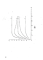
Fig. 3 is the people different to health status, the graph of a relation between driving voltage and its response current;
Fig. 4 is an exemplary of exiting signal generating circuit 40 among Fig. 1;
Fig. 5 A is two different embodiments of little current amplification circuit 50 among Fig. 1 with 5B;
Fig. 6 is the time dependent characteristic curve of response current that the different people of health status produces driving voltage;
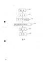
Fig. 7 A is two different embodiments of signal processing circuit 60 among Fig. 1 with 7B;
Fig. 8 is the pairing signal waveforms of each node among Fig. 7 A;
Fig. 9 is the program flow diagram that uses in the embodiment shown in Fig. 7 B;
Figure 10 is the structural representation of an exemplary of detecting electrode 20 among Fig. 1;
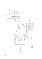
Figure 11 is the circuit theory diagrams of the 3rd embodiment of checkout gear of the present invention; With
Figure 12 is that the detecting electrode of checkout gear of the present invention is to the pressure of skin and the graph of a relation between ambient temperature and the humidity.
Below referring to accompanying drawing, give detailed explanation to the basic design philosophy and the several exemplary embodiments of bioelectric signal measuring apparatus of the present invention.
Referring to Fig. 1, be depicted as the schematic block diagram of checkout gear of the present invention.Wherein, reference number 10 expression these checkout gears itself, detecting electrode of 20 expressions has holding wire 203 and control line 2011 on it, reference electrode that constitutes by foil of 30 expressions, it can adopt any medical conventional chip detecting electrode, exiting signal generating circuit of reference number 40 expressions, little current amplification circuit of 50 expressions, signal processing circuit of 60 expressions, 70 expression signal output apparatus, the concrete structure of above each several part will describe in detail respectively hereinafter.
Referring to Fig. 2, be depicted as when utilizing checkout gear of the present invention under identical test condition, one group of normal person to be measured, the statistical Butut of the response current value that measures corresponding to different driving voltages, data among the figure are that reference electrode is placed on the Yintang acupoint of forehead, and the measured value that exciting electrode obtains by different driving voltage repeated measure on same group of acupuncture point.Abscissa is the value of driving voltage Vs among the figure, and unit is a volt, and ordinate is the response current I that measures
1Negative logarithm N, N=-logI
1, work as I
1=10
-7Ampere-hour, N=7.As seen from the figure, as driving voltage Vs during greater than 3.0 volts, the discreteness of measured value is very little, and measured value is basicly stable, increases with voltage hardly to change.When driving voltage during less than 1.0 volts, on the one hand, significant variation takes place with the variation of voltage in current measurement value, on the other hand, and in the middle of same group of experimenter, the discreteness of measured value significantly increases, at this moment measurement is increased by the interference of environmental factors greatly, and from the data of Fig. 2 as seen, (less than 1.0 volts) measured value discreteness was big when driving voltage was too small, be difficult for carrying out statistical procedures, be difficult to obtain the valuable information that diagnoses the illness.
Referring to Fig. 3, be depicted as when utilizing checkout gear of the present invention under identical test condition, several groups of people that suffered from various disease through clinical definite to be tested, different driving voltages and the response current that measures every group of patient are born the relation curve between the logarithmic meansigma methods, the connotation of abscissa and ordinate is same as shown in Figure 2 among the figure, and wherein curve 3 is profiles of statistical distribution value average shown in Figure 2.Curve 1 is one group of insane measurement curve of manic type, and curve 2 is curves of one group of slight autonomic nervous dysfunction patient, and curve 4 is curves of one group of slight dysbolismus patient, and curve 5 is curves of one group of patient with advanced cancer.From several curves shown in Figure 3 as can be seen, along with driving voltage increases, the patient's who is in a bad way measured value (curve 1 and 5) and normal person, (curve 3) still keeps bigger difference, but to the patient of early lesion, its measured value (curve 3 and 4) is more approaching with normal person's (curve 3).If the discreteness (as shown in Figure 2) of measured value when considering actual measurement, this makes the patient of normal person and early lesion be difficult to difference, in other words, when driving voltage is relatively large, this outside pumping signal " is flooded in vivo relevant with early lesion signal network ", thereby can't carry out the diagnosis of early lesion.As can be seen from Fig. 3, when driving voltage Vs was within the scope of 1.0-3.0 volt, the difference between each curve was the most remarkable.
By as can be seen in conjunction with the given data of Fig. 2 and Fig. 3, utilize device of the present invention to carry out body electrical signals when measuring, driving voltage should be selected in the 1.0-3.0 volt scope, and preferably 2.0 volts,
Referring to Fig. 4, be depicted as an exemplary of exiting signal generating circuit 40 among Fig. 1.Wherein 401 is circuits for triggering, and it can be at the triggering signal V of signal processing circuit output
3Control under, produce the very steep broad-adjustable step signal of rising edge at its outfan, the amplitude of this step signal is 2.0 volts by clamp diode 402 clamps, and exports through reference electrode as driving voltage Vs.Adopt amplitude fluctuations that clamp diode 402 can guarantee driving voltage Vs less than 1%, avoid because the fluctuation of the detection electric current that the driving voltage instability causes with this.According to principle shown in Figure 4 as can be known, the regulated power supply of any routine all can be used as the exiting signal generating circuit of this device, if this circuit can produce the very steep step excitation signal of rising edge under the control of signal processing circuit, then the accuracy of detected response current can further improve.
Referring to Fig. 5 A, be depicted as an embodiment of little current amplification circuit 50 among Fig. 1, in Fig. 5 A, 50A represents this amplifying circuit itself, and frame of broken lines 501A represents a logarithm micro current amplifier, and it is by operational amplifier OP
1And transistor T
1A constitutes logafier, and frame of broken lines 502A represents a temperature-compensation circuit, and wherein I is a constant-current source, T
1T among b and the 501A
1A is that an audion is right, by T
1B is to T
1The parallel lines of a temperature drift partly compensate, and Rt and R are to T
1The slope of a temperature drift partly compensates, and also determines the amplification of this compensating circuit simultaneously.Frame of broken lines 503A represents a phase inverter, wherein, and by OP
3The amplified current signal is carried out paraphase, W
1Be output zero potentiometer, W
2For output full scale regulator potentiometer, in Fig. 5 A, diode D
1, D
2, D
3Play clamping action respectively, utilize the logarithm micro current amplifier shown in Fig. 5 A 10
-4-10
-11When little electric current of ampere amplifies, require operational amplifier OP
1Minimum working current should be 10
-12Ampere, this is the index that has reached in the prior art, therefore is not described further.
Referring to Fig. 5 B, be depicted as another embodiment of little current amplification circuit 50 among Fig. 1.Wherein, 50B represents this amplifying circuit itself.T
1And T
2Be technotron, constitute the differential input stage of this circuit, T
3And R
3Constitute the constant-current source equivalent resistance of this difference amplifier, T
4And T
5Constitute second level difference and amplify, Re is a constant current resistance, and stabilivolt D is with T
1And T
2The leakage pressure-controlled use the district in suitable linearity, and and T
3The negative feedback that constitutes the open loop amplifier is to stablize T
1, T
2The operating point, T
6For penetrating and the follower output stage r
1r
2For preventing the resistance of unwanted oscillation, when adopting circuit shown in the discrete component pie graph 5B, T
1And T
2Characteristic should strict symmetry, can select for use the 2N4416 of U.S. TEXAS company or 2N3823 high frequency low noise technotron or in homemade 3DJ series high frequency low noise technotron (as 3DJ2F).Require pipe grid current ig≤10
-12A ', the feedback circuit that constitutes by selector switch S and connected parallel resistance network N in Fig. 5 B can be to this amplifier by 10 end index steppings, and in each shelves, the input and output of amplifier are linear relationship.
Referring to Fig. 6, be depicted as and utilize checkout gear of the present invention, when under identical test condition, several groups of people that suffered from various disease through clinical definite being tested, each organizes the time response curve of the response current that patient measures, and when measuring, driving voltage adopts is 2.0 volts step voltage, abscissa is a time shaft among the figure, unit is second, and zero point, ordinate was the negative logarithm of response current corresponding to the rising edge of step voltage.Identical among the pairing five groups of patients of five curves among Figure 16 and Fig. 3, wherein, curve 3 is time response curves of response current that the normal person is measured, curve 1 is corresponding to one group of insane measurement curve of manic type, curve 2 is curves of one group of slight autonomic nervous dysfunction patient, curve 4 is curves of one group of slight dysbolismus patient, and curve 5 is curves of one group of patient with advanced cancer.From curve shown in Figure 6 as can be seen, when utilizing checkout gear of the present invention on particular acupoint, to detect, detected response current can reveal certain variation tendency along with timetable, the different variation tendencies that patient showed are different, therefore, this variation tendency also can be used for auxiliary diagnosis.Among the figure as seen, the patient's who is in a bad way temporal characteristics curve (curve 1 and 5) is bigger with normal person's (curve 3) difference, the patient's of early lesion temporal characteristics curve (curve 2 and 4) then show in time passing and to the close trend of normal person, data from figure as can be seen, within the 1-2 scope of second, the value difference of the response current that different patients measure is not more remarkable, therefore, adopt when protecting circuit response current being sampled in use, sampling time should postpone preferably to adopt 1.5 seconds time delay in the 1-2 scope of second after the pumping signal rising edge.Should be understood that, Fig. 2 and measured value shown in Figure 3 all are the sampled values with 1.5 seconds delay time measurement, in addition, if curve shown in Figure 6 is carried out multi-point sampling, can obtain the rate of rise of temporal characteristics curve, extreme value, parameters such as descending slope, these parameters all can be used for auxiliary diagnosis and difference disease, the state of an illness.
Referring to Fig. 7 A, be depicted as an embodiment of the signal processing circuit among Fig. 1, the principal character of this scheme is the characteristic that is showed according to response current time response curve shown in Figure 6, at special time this curve is sampled, and obtains Useful Information with this.Frame of broken lines 60A represents signal processing circuit itself among the figure, circuits for triggering of 601 expressions, the input signal V of this circuit
1From a trigger switch on the detecting electrode 20, at signal V
1Triggering under, this circuits for triggering produce two output signal V
2And V
3, signal V
3Output to exiting signal generating circuit shown in Figure 4 40, with generation, the signal V of control step excitation signal
2Input adjustable delay circuit 602, control sampling frequency signal V
 Generation.Sampling hold circuit of 603 expressions, it is at sampling frequency signal V
Control under, to the little current amplification circuit among Fig. 1 50 output with little electric current I
1Corresponding amplifying signal I
2The maintenance of sampling, and with its result as output signal I
3Give signal output apparatus 70,, no longer be elaborated because the parts that each block diagram adopts shown in Fig. 7 A are prior art.
Generation.Sampling hold circuit of 603 expressions, it is at sampling frequency signal V
Control under, to the little current amplification circuit among Fig. 1 50 output with little electric current I
1Corresponding amplifying signal I
2The maintenance of sampling, and with its result as output signal I
3Give signal output apparatus 70,, no longer be elaborated because the parts that each block diagram adopts shown in Fig. 7 A are prior art.
Fig. 8 illustrates the signal waveforms of respective points among Fig. 7, wherein V
1Be the triggering signal that is produced by trigger switch on the detecting electrode, the structure of detecting electrode will be in following explanation, the rising edge A of this triggering signal
1Depend on the operation of tester, A to detecting electrode
1To B
1The length of width time of staying of depending on detecting electrode on the patient acupuncture point, A
1To next triggering signal A
2Distance depend on that also the tester carries out the operation when measuring of next acupuncture point.Therefore, the distance between the width of this triggering signal and two triggering signals all depends on the operator.V
2Be the negative pulse that is produced by circuits for triggering 601, the width of this pulse pre-determines according to the needs of sampling hold circuit 603, and its forward position is by V
1Rising edge A
1And A
2Decision.V
3Be a positive pulse that is produced by circuits for triggering, exiting signal generating circuit 40 produces a step excitation signal or a pulse excitation signal, V in its control figure 1
3Width pre-determine I according to the needs of sample circuit 603
2Be the output signal of little current amplification circuit 50, it is corresponding under the driving voltage effect, the response current that produces on the human body particular acupoint, and its waveform is corresponding with curve shown in Figure 6, I
2Trailing edge and V at a C
3Trailing edge corresponding, when driving voltage reduces to zero, I
2Descend exponentially.V
Be adjustable delay circuit, 602 sampling frequency signals that produce, this signal is a negative pulse, its forward position and signal V
2The negative pulse forward position keep a fixed delay
(for example
=1.5 seconds), guarantee the specified point on the temporal characteristics curve among Fig. 6 is sampled with this.I
3Be the signal waveform of sampling hold circuit output, it can be presented on the signal output apparatus 70 by the form of analog or digital.Should be pointed out that according to the same scheme shown in Fig. 7 A available sequence circuit replaces adjustable delay circuit 602, at V
2Sampling period between in produce a plurality of sampling frequency signals, and carry out multi-channel sampling by multi-path sampling holding circuit and line output, can obtain useful informations such as time response slope of a curve, extreme value like this.
Referring to Fig. 7 B, be depicted as another embodiment of signal processing circuit 60 among Fig. 1, in Fig. 7 B, frame of broken lines 60B represents this signal processing circuit itself.Wherein, circuits for triggering of 601 expressions, its 26S Proteasome Structure and Function is with identical shown in Fig. 7 A; A/D converter of 604 expressions, it is with the analogue signal I of little current amplification circuit 50 outputs
2Be converted to digital signal, so that central processing unit (CPU) 605 is handled.CPU605 is at triggering signal V
2Triggering under, according to the working procedure that keeps in advance in the memorizer 606 digital signal of A/D converter 604 outputs is handled, signal after will handling then is through input/output interface 607 outputs, the signal of output can comprise the pointwise graphy figure to the time response curve of acupuncture point response current after CPU605 handles, the rate of rise of this curve, extreme value, descending slope, reach the time of extreme value, with difference of normal value or the like.By supervisory keyboard 703, also can be with patient's name, age, tested acupuncture point coding is measured information inputs such as date, so that the storage of the information of carrying out and later statistical disposition, but the demonstration of this part and 701 is printed, functions such as 702 external memory all belong to prior art, do not have direct relation with the present invention, therefore no longer describe in detail.Should be pointed out that if for the simple time response curve that demonstration measured, also can be with the signal I of little current amplification circuit 50 outputs
2Be directly inputted on the curve tracing device of oscillograph or routine, therefore the oscillograph or the curve tracing device of available routine replace signal processing circuit 60 of the present invention and signal output apparatus 70 to carry out the processing and the demonstration of time response curve, because above-mentioned two kinds of devices are prior art, do not give unnecessary details for this reason.
Fig. 9 illustrates the schematic block diagram of working procedure of the CPU605 of Fig. 7 B.Wherein: step 100 is a setting up procedure, and it depends on the output signal V of circuits for triggering 601
2The forward position; Step 110 is A/D peek step, and it obtains digitized measuring-signal from A/D converter 604, and step 120 is a storing step, and it deposits the measurement data that obtains in built-in storage 606, so that later computing; Step 130 is the information processing step, it is according to the rate of rise of the measurement data of having obtained to the time response curve, extreme value, descending slope, the parameters such as time that reach extreme value are calculated, and can with the parameter calculated and normal value compares or carry out statistical disposition; Step 140 is the output step; it can output on the signal output apparatus 701 result who measures to show or to print; also this result can be sent to external memory 702; enter after information processing and output are finished and shut down step 150, should be pointed out that above each step is prior art; therefore no longer its concrete details is described in detail; in addition, the further date processing of the information that this device is measured has exceeded scope of the present invention, is also no longer illustrated.
Referring to Figure 10, be depicted as the structural representation of an exemplary of detecting electrode 20 among Fig. 1.Wherein, reference number 20 expression detecting electrodes itself; Metal probe of 201 expressions, its diameter are in 1.0-2.0 millimeter scope, and its end is slick and sly so that keep well contacting with skin point but prick skin not; The metal screen layer of 202 these detecting electrodes of expression, it gets up whole metal probe 201 shieldings, makes it not be subjected to the interference of environment; Coaxial cable of 203 expressions, its inner wire is connected with metal probe 201, and outer conductor is connected with screen layer 202; Spring of 204 expressions, the one end is fixed on the screen layer 202 by insulating part 2014, and the other end is fixed on the probe 201 by insulating part 2013; Hairspring of 205 expressions, by adopting the structure of spring 204 and hairspring 205, make metal probe 201 do axially-movable with respect to screen layer 202, and the elastic force of spring 204 makes probe 201 tend to set back, hairspring 205 has guaranteed that the good electrical in the motor process connects.Like this, when probe 201 contacted with the acupuncture point, spring 204 made its maintenance to the acupuncture point one constant compression force be arranged.Insulation driving lever of 206 expressions, its end stretches out by a slit on the screen layer 202, and the other end is fixed on the probe 201.Therefore can move with probe; Trigger switch of 207 expressions, when driving lever 206 was in contact with it with probe motion, it can send a triggering signal V to signal processing circuit 60 by line 2011
1Insulating cylinder of 208 expressions, it make probe 201 and screen layer 202 insulation and make probe within it portion slide along axis.209 is an adjustable insulating sleeve, it by with the engaging structure of screen layer 202, can adjust its position along axis thereon, change the length that probe 201 stretches out from its end face with this, when probe contacts with skin point, equal and the contact skin of the front end face of the front end of probe 201 and adjustable insulating sleeve 209, at this moment the pressure at 201 pairs of acupuncture points of probe just depends on that probe returns to the position upper spring 204 concordant with the adjustable sleeve front end face to its applied pressure from its normal position, adjustable sleeve 209 on the screen layer 202 when the opposite direction of end face is adjusted, probe 201 extension from sleeve 209 is just longer relatively, pressure to the acupuncture point during detection is just bigger, otherwise pressure is just less, realizes quantitative adjustment to probe pressure with this, 2010 is the insulation crust of detecting electrode, and it makes screen layer and operator's hands insulation; To avoid operator's interference, 2012 is an insulating barrier, keeps the insulation of probe line and screen layer.As can be seen from Fig. 10, the inner wire of coaxial cable is exported detected little current signal I, lead-in wire 2011 output triggering signal V
1, interfering with each other for preventing them, trigger switch 207 and going between 2011 all is contained in outside the screen layer 202.
Referring to Figure 11, be depicted as the signal processing of checkout gear of the present invention and another embodiment of display part.In this embodiment, the signal processing circuit 60 among Fig. 1 is made of the comparator of a pair of parallel connection, and signal output apparatus 70 is replaced by a pair of light emitting diode that is connected with this comparator respectively.This embodiment with and simple circuit realize qualitative demonstration to testing result.In Figure 11,610A represents first comparator, and its inverting input links to each other with the outfan of little current amplification circuit 50, in-phase input end and threshold value V
Th1Link to each other, outfan links to each other with light emitting diode 710A.610B represents second comparator, and its in-phase input end links to each other with the outfan of little current amplification circuit 50, inverting input and threshold value V
Th2Link to each other, outfan links to each other with light emitting diode 710B, is connected with a cut-off circuit 630 between the outfan of second comparator 602 and light emitting diode 710B, and this circuit is by audion T
1, stabilivolt D
1Constitute with resistance r.In addition, the first and second threshold value V
Th1And V
Th2Produced by same potential-divider network 620, this potential-divider network is by a stabilivolt D
2Divider resistance constitutes with connecting with its group of being connected in parallel.During detection, by the signal I of little current amplification circuit 50 outputs
2Produce an input voltage U at the inverting input of comparator 610A and the in-phase input end of 610B
2, by the circuit analysis among the figure as can be known, work as V
Th1<U
2<V
Th2The time, comparator 610A is output as negative, and also for negative, two light emitting diodes are all luminous in the output of 610B, expression U
2In range of normal value; Work as U
2<V
Th1The time, 610A just is output as, and 610B is output as negative, and 710A is not luminous, and 710B is luminous; Work as U
2>V
Th2The time, 610A is output as negative, and 610B just is output as, and 710A is luminous, and 710B is not luminous.By adjusting circuit parameter, can make V
Th1With detected little current value I
1=10
-8Order of amps is corresponding, V
Th2Corresponding to I
1=10
-6Order of amps can demonstrate I respectively by above circuit
1<10
-8Order of amps (710A does not work, and 710B is bright), 10
-8<I
1<10
-6Order of amps (710A and 710B are all luminous); With 10
-6A<I
1(710A is luminous, and 710B is not luminous).Like this, just realized qualitative demonstration to detected little current signal, and with 10
-8-10
-6Order of amps is as the range of normal value of little electric current.As checkout gear open circuit I
2=0 o'clock, U
2=0,610A just is output as, and 610B is output as negative saturated output, at this moment the stabilivolt D in the cut-off circuit 630
1Conducting, resistance r goes up the pressure drop that produces and makes audion T again
1Saturation conduction, and light emitting diode 710B is cut off.Like this, work as U
2=0 o'clock, two light emitting diode 710A and 710B were all not luminous, therefore can not produce wrong shows signal when open circuit.
By the circuit of Figure 11 as seen, because output signal wherein just shows measurement result qualitatively, thereby the requirement of circuit reduced greatly, circuit is greatly simplified, and significantly reduced cost, this device can be carried by patient, and be used for daily health care and the treatment, in addition, owing to do not adopt step excitation signal and sampling hold circuit in this embodiment, therefore, user can be on skin slip detecting electrode continuously, until the value of showing abnormality, this just makes it can be used for seeking special acupuncture point.
Referring to Figure 12, the detecting electrode that is depicted as checkout gear of the present invention is to the pressure of skin point and the graph of a relation between ambient temperature and the humidity, as indicated above, when the probe of detecting electrode to the pressure of skin not simultaneously, can the accuracy of measuring be affected.On the other hand, because the temperature and humidity difference of environment can influence the blood flow of capillary of skin, thereby influence skin resistance, therefore also can influence the accuracy of measurement.Device of the present invention can come compensation temperature and humidity to change the influence that causes to the pressure of skin point by adjusting probe, shown in Figure 12 for the relation between device pressure of the present invention and temperature, wherein abscissa is a temperature, unit be degree centigrade (℃), ordinate is a pressure, and unit is a gram.Curve 2 is corresponding to lower temperature among the figure, when relative humidity increases by 20% left and right sides, pressure should correspondingly reduce about 20 grams, device of the present invention is by adjusting the position change probe 201 telescopic distances of the tube adjusted 209 among Figure 10, because the pressure of spring 204 is directly proportional with the distance of its compression, therefore, can adjust the pressure of probe to the acupuncture point quantitatively, for the ease of the user adjustment, can engrave the pairing temperature in each position according to the curve of Figure 12 at adjustable sleeve 209.
Should be pointed out that except the detecting electrode shown in Figure 10 the also available acupuncture needle of checkout gear of the present invention is as detecting electrode and/or reference electrode.Like this, just made things convenient for acupuncturist to carry out the diagnosis of disease and the monitoring of curative effect with device of the present invention.When using acupuncture needle as detecting electrode and/or reference electrode, because this formula electrode that thrusts has been got rid of the influence of skin resistance to detecting, the driving voltage that exiting signal generating circuit among Fig. 1 and Fig. 4 produces correspondingly can be adjusted into about 0.5 volt, at this moment the result of Ce Lianging can remain unchanged basically.
The operation principle and the structure of bioelectric signal measuring apparatus of the present invention below have been described with reference to the accompanying drawings, have no to ask with fixed attention, for the skilled person in this area, need not deviate from essence of the present invention and principle, can make multiple modification and conversion to above-mentioned embodiment, therefore, above embodiment only can be used as and helps to understand and illustrate example of the present invention.Protection scope of the present invention only depends on claims of patent application.
Claims (14)
1, a kind of bioelectric signal measuring apparatus comprises:
The detecting electrode of the signal of telecommunication that contacts with Chosen Point on the person and detect;
A reference electrode that is fixed on the human body skin and pumping signal is added in the reference point on the human body;
One link to each other with above-mentioned detecting electrode and to detected little electric current 10
-4-10
-11The amplifying circuit that amplifies in the order of amps scope;
The pumping signal generator of the driving voltage that links to each other with detecting electrode and provide;
It is characterized by:
Detecting electrode, reference electrode, one of the common formation of amplifying circuit and pumping signal generator detects the loop, is used for the detection of biological signal of telecommunication;
This device also comprises:
A signal processing circuit, it links to each other with the output of amplifying circuit, and its output signal is handled;
A signal output apparatus, it links to each other with the output of above-mentioned signal processing circuit, is used to export testing result;
Wherein, amplifying circuit comprises a logarithm micro current amplifier, a temperature-compensation circuit and a negative circuit, the input of micro current amplifier links to each other with detecting electrode, outfan links to each other with the input of temperature-compensation circuit, the outfan of temperature-compensation circuit links to each other with the input of negative circuit, and signal processing circuit is given in the output of negative circuit.
2, bioelectric signal measuring apparatus according to claim 1, it further is characterized as:
The driving voltage that the device of described generation pumping signal produces is the DC voltage in the 0.5-3.0 volt scope.
3, bioelectric signal measuring apparatus according to claim 1, it further is characterized as:
Described amplifying circuit comprises:
One first differential amplifier circuit;
One second differential amplifier circuit;
An emitter follower circuit; With
A feedback circuit that constitutes by resistor network and selector switch;
Wherein, the input of first differential amplifier circuit is connected with above-mentioned detecting electrode, its outfan is connected with the input of second differential amplifier circuit, the outfan of second differential amplifier circuit is connected with the input of emitter follower circuit (base stage), the outfan of emitter follower circuit is connected with the input of above-mentioned signal processing circuit, above-mentioned feedback circuit is connected between the outfan of the input of first differential amplifier circuit and emitter follower circuit, can change the amplification of amplifying circuit by selector switch, be implemented in 10
-4-10
-11Press linear little current amplification circuit of index stepping in the scope of order of amps.
4, bioelectric signal measuring apparatus according to claim 1, it further is characterized as:
Described detecting electrode comprises:
An inner wire;
An outer conductor that this inner wire is formed shielding;
A coaxial cable, its inner and outer conductor are connected with above-mentioned inner and outer conductor respectively; With
Test side at above-mentioned internal and external conductor keeps the insulating barrier of its mutually insulated;
Wherein, inner wire keeps AT with point skin and contacts in testing process, outer conductor and skin insulation.
5, bioelectric signal measuring apparatus according to claim 1, it further is characterized as:
Described detecting electrode comprises:
An inner wire that constitutes by acupuncture needle;
An outer conductor that this inner wire is formed shielding;
A coaxial cable, its inner and outer conductor are connected with above-mentioned inner and outer conductor respectively; With
Test side in above-mentioned inner and outer conductor keeps the insulating barrier of its mutually insulated;
Wherein, in testing process, inner wire thrusts tested acupuncture point, outer conductor and skin insulation, and the driving voltage that the device of described generation pumping signal produces is the DC voltage in the 0.5-1.5 volt scope.
6, bioelectric signal measuring apparatus according to claim 4, it further is characterized as:
Described detecting electrode further comprises:
An elastic device, its two ends respectively with insulation mode be fixed on above-mentioned in, on the outer conductor, make inner wire relatively outer conductor do axial elasticity motion, make inner wire in the testing process keep constant with this to the pressure at acupuncture point.
7, bioelectric signal measuring apparatus according to claim 6, it further is characterized as:
Described detecting electrode further comprises:
A pressure regulation device, this device is installed on the test side of above-mentioned outer conductor, and outer conductor is adjusted its position vertically relatively, changes the distance of the relative outer conductor of inner wire motion with this, is applied to pressure on the acupuncture point thereby adjust by elastic device by inner wire.
8, one it further is characterized as according to any one bioelectric signal measuring apparatus among the claim 1-7,
Described signal processing circuit comprises:
A delay circuit; With
A sampling hold circuit;
Wherein, the output signal control sampling hold circuit of this delay circuit is to detect a result that the regular time delay is sampled and kept sampling the output signal of above-mentioned amplifying circuit after beginning, so that by above-mentioned signal output apparatus testing result is exported.
9, one according to any one bioelectric signal measuring apparatus among the claim 1-7, and it further is characterized as:
Described signal processing circuit comprises:
An A/D converter;
A central processing unit;
A memorizer;
An interface circuit; With
A supervisory keyboard;
Wherein, the input of this A/D converter is connected with the outfan of above-mentioned amplifying circuit, and its simulation output is converted to digital signal, this digital signal is imported above-mentioned central processing unit by data wire, this digital signal is handled according to the working procedure of storing in the memorizer with by the instruction of keyboard input by it, its result is sent to above-mentioned signal output apparatus by interface circuit.
10, one it further is characterized as according to any one bioelectric signal measuring apparatus among the claim 1-7,
Described signal processing circuit comprises:
A threshold value bleeder circuit, two outfans of this circuit can produce a upper limit threshold signal and a lower threshold signal respectively;
The a pair of comparator that links to each other with above-mentioned upper and lower bound threshold signal outfan with the outfan of above-mentioned amplifying circuit respectively is by comparing the output signal of amplifying circuit respectively, to determine the span of this signal with this upper and lower bound threshold signal;
The a pair of display device that is connected with the outfan of above-mentioned a pair of comparator respectively is according to the signal demonstration result relatively of comparator output; And
The output that a clamp circuit, this circuit make comparator in the time of can being zero in the output signal of above-mentioned amplifying circuit is by clamp, thereby above-mentioned signal display apparatus is not worked.
11, bioelectric signal measuring apparatus according to claim 6 or 7, it further is characterized as,
Described detecting electrode further comprises, a trigger switch, and when above-mentioned inner wire contacted with the acupuncture point with certain pressure, a triggering signal took place in this trigger switch;
Described signal processing circuit comprises circuits for triggering, and these circuits for triggering link to each other with above-mentioned trigger switch and receive its triggering signal, and exports the control signal of the device of enabling signal treatment circuit and generation pumping signal according to this triggering signal;
The device of described generation pumping signal comprises a controlled circuit that links to each other with above-mentioned circuits for triggering, and it produces pumping signal under the control of above-mentioned control signal.
12, bioelectric signal measuring apparatus according to Claim 8, it further is characterized as,
Described detecting electrode further comprises a trigger switch, and when above-mentioned inner wire contacted with the acupuncture point with certain pressure, this trigger switch produced a triggering signal;
Described signal processing circuit further comprises circuits for triggering, and these circuits for triggering link to each other with above-mentioned trigger switch, and makes it produce a sampling delay signal to control signal of above-mentioned delay circuit generation when receiving triggering signal;
The device of described generation pumping signal comprises a controlled circuit, and it links to each other with above-mentioned circuits for triggering and produce a pumping signal under the control of its output signal.
13, bioelectric signal measuring apparatus according to claim 9, it further is characterized as,
Described detecting electrode further comprises a trigger switch, and when above-mentioned inner wire contacted with the acupuncture point with certain pressure, this trigger switch sent a triggering signal;
Described signal processing circuit further comprises circuits for triggering, and it links to each other with above-mentioned trigger switch and when receiving triggering signal, sends an enabling signal to above-mentioned central processing unit, makes it begin to carry out handling procedure to detection signal;
The device of described generation pumping signal comprises a controlled circuit, and it links to each other with above-mentioned circuits for triggering and produce a pumping signal under the control of its output signal.
14, bioelectric signal measuring apparatus according to Claim 8, it further is characterized as:
The output signal control sampling hold circuit of described delay circuit is sampled to the output signal of above-mentioned amplifying circuit with a fixed delay time in 1.0-2.0 scope second of detection beginning back and is kept sampled result.
Priority Applications (6)
| Application Number | Priority Date | Filing Date | Title |
|---|---|---|---|
| CN86105980A CN1012257B (en) | 1986-09-09 | 1986-09-09 | Bioelectric signal measuring apparatus |
| US07/094,621 US4940060A (en) | 1986-09-09 | 1987-09-09 | Apparatus for detecting bioelectric signals |
| CA000546399A CA1310373C (en) | 1986-09-09 | 1987-09-09 | Apparatus for detecting bioelectric signals |
| EP87113186A EP0269796B1 (en) | 1986-09-09 | 1987-09-09 | Apparatus for detecting bioelectric signals |
| AT87113186T ATE97799T1 (en) | 1986-09-09 | 1987-09-09 | DEVICE FOR DETECTING BIOELECTRIC SIGNALS. |
| DE87113186T DE3788339T2 (en) | 1986-09-09 | 1987-09-09 | Device for the detection of bioelectric signals. |
Applications Claiming Priority (1)
| Application Number | Priority Date | Filing Date | Title |
|---|---|---|---|
| CN86105980A CN1012257B (en) | 1986-09-09 | 1986-09-09 | Bioelectric signal measuring apparatus |
Publications (2)
| Publication Number | Publication Date |
|---|---|
| CN86105980A CN86105980A (en) | 1988-03-23 |
| CN1012257B true CN1012257B (en) | 1991-04-03 |
Family
ID=4803041
Family Applications (1)
| Application Number | Title | Priority Date | Filing Date |
|---|---|---|---|
| CN86105980A Expired CN1012257B (en) | 1986-09-09 | 1986-09-09 | Bioelectric signal measuring apparatus |
Country Status (6)
| Country | Link |
|---|---|
| US (1) | US4940060A (en) |
| EP (1) | EP0269796B1 (en) |
| CN (1) | CN1012257B (en) |
| AT (1) | ATE97799T1 (en) |
| CA (1) | CA1310373C (en) |
| DE (1) | DE3788339T2 (en) |
Cited By (1)
| Publication number | Priority date | Publication date | Assignee | Title |
|---|---|---|---|---|
| CN100434913C (en) * | 2006-07-25 | 2008-11-19 | 暨南大学 | Lithangiuria intelligent diagnosing instrument based on five-electrode method |
Families Citing this family (48)
| Publication number | Priority date | Publication date | Assignee | Title |
|---|---|---|---|---|
| JPH01288233A (en) * | 1988-02-20 | 1989-11-20 | Hiroshi Motoyama | Bioinformation measuring instrument |
| FR2636525A1 (en) * | 1988-09-20 | 1990-03-23 | Feber Alain | ELECTRONIC DEVICE AUTOMATICALLY PROVIDING DETECTION OF ACUPUNCTURE POINTS, MESOTHERAPY, REFLEXOTHERAPY, DIAGNOSIS OF ENERGY IMBALANCES AND APPLICATION OF APPROPRIATE TREATMENTS |
| US5144554A (en) * | 1989-03-04 | 1992-09-01 | Xueshan Zhang | Apparatus for diagnosing and providing therapy for gastrointestinal diseases without causing patient discomfort and injury |
| US5381805A (en) * | 1990-01-24 | 1995-01-17 | Topical Testing, Inc. | Cutaneous testing device for determining nervous system function |
| US5363859A (en) * | 1990-01-24 | 1994-11-15 | Topical Testing, Inc. | Tactile testing device and methods |
| CN1047511C (en) * | 1992-03-19 | 1999-12-22 | 方祖祥 | No low-frequency distortion DC isolating tech. and circuit thereof |
| US5366483A (en) * | 1993-05-12 | 1994-11-22 | Grigory Sadkhin | Method and apparatus for use in treating biologically active points on a patient's skin |
| AT401342B (en) * | 1995-01-17 | 1996-08-26 | Myles Handels Gmbh | SOFTLASER WITH INTEGRATED POINT DETECTOR FOR ACUPUNCTURE POINTS |
| US5797854A (en) * | 1995-08-01 | 1998-08-25 | Hedgecock; James L. | Method and apparatus for testing and measuring current perception threshold and motor nerve junction performance |
| DE19717766A1 (en) * | 1997-04-26 | 1998-10-29 | Erich Rasche | Measurement device for objective measurement and evaluation of electrical parameters and their characteristics |
| CN1051021C (en) * | 1998-05-26 | 2000-04-05 | 吴庆民 | Auricle treatment device for giving up syndrome |
| DE19911200A1 (en) * | 1999-03-13 | 2000-09-21 | Bruno M Hess | Device for measurement of bio-electric parameters such as voltage and resistance of skin or tissue between acupuncture points in a human or animal has opposite polarity constant current sources and measurement electrodes |
| FR2835732B1 (en) * | 2002-02-11 | 2004-11-12 | Spinevision | DEVICE FOR TRACKING THE PENETRATION OF A PENETRATION MEANS IN ANATOMICAL ELEMENTS |
| US6830550B2 (en) * | 2002-06-25 | 2004-12-14 | James Lee Hedgecock | Stair step voltage actuated measurement method and apparatus |
| BR0314328A (en) * | 2002-09-04 | 2005-07-05 | William F Urmey | Positioning system for a nerve stimulating needle |
| US20040158166A1 (en) * | 2003-02-10 | 2004-08-12 | Levengood William C. | Method and apparatus for detecting, recording and analyzing spontaneously generated transient electric charge pulses in living organisms |
| US20040215285A1 (en) * | 2003-04-22 | 2004-10-28 | Pollock Frederick William | Pain relief device |
| US7542796B2 (en) * | 2003-07-16 | 2009-06-02 | Biomeridian International, Inc. | Methods for obtaining quick, repeatable, and non-invasive bioelectrical signals in living organisms |
| US7937139B2 (en) * | 2004-07-20 | 2011-05-03 | Biomeridian International, Inc. | Systems and methods of utilizing electrical readings in the determination of treatment |
| US20060129058A1 (en) * | 2004-12-13 | 2006-06-15 | Power Equine | Electromyogram for animals |
| AU2007320723A1 (en) * | 2006-11-13 | 2008-05-22 | Medex Screen Ltd. | Diagnostic system |
| US20090128513A1 (en) * | 2007-11-20 | 2009-05-21 | Samsung Electronics Co., Ltd | Device identification method and apparatus, device information provision method and apparatus, and computer-readable recording mediums having recorded thereon programs for executing the device identification method and the device information provision method |
| US8917247B2 (en) | 2007-11-20 | 2014-12-23 | Samsung Electronics Co., Ltd. | External device identification method and apparatus in a device including a touch spot, and computer-readable recording mediums having recorded thereon programs for executing the external device identification method in a device including a touch spot |
| CN101816549B (en) * | 2010-03-09 | 2012-06-27 | 东南大学 | Nerve signal detection/excitation electrode, twin-electrode, electrode array and preparation methods thereof |
| CN102859875B (en) * | 2010-04-22 | 2016-10-05 | 皇家飞利浦电子股份有限公司 | Skin contact detector |
| CN101947357B (en) * | 2010-10-18 | 2013-01-02 | 刘辉 | Device for treating epilepsia |
| CN102495270B (en) * | 2011-12-27 | 2014-08-13 | 苏州华芯微电子股份有限公司 | Satellite reception control signal detection circuit |
| CN103149438A (en) * | 2013-01-24 | 2013-06-12 | 上海帝仪科技有限公司 | Brain electrical contacting resistance detection method and device |
| CN103083015A (en) * | 2013-01-30 | 2013-05-08 | 王洪福 | Biological wave current meridian detection treatment instrument |
| CN103315732B (en) * | 2013-07-09 | 2015-03-25 | 丁新生 | Specific acupoint electrograph meter for selecting human body acupoint bio-electricity signal |
| CN104287729B (en) * | 2013-07-19 | 2016-12-28 | 喻可芳 | Meridians detection Apparatus for () and method therefor |
| CN104739406A (en) * | 2013-12-30 | 2015-07-01 | 中国医学科学院生物医学工程研究所 | Evaluation method of acupuncture stimulation effect |
| CN105011924A (en) * | 2015-06-16 | 2015-11-04 | 电子科技大学 | Micro-miniature multi-functional high-precision physiological electricity acquisition device |
| KR102311079B1 (en) * | 2015-09-25 | 2021-10-13 | 주식회사 세라젬 | Control method for real-time scan of human body |
| CN105388276B (en) * | 2016-01-01 | 2017-08-04 | 河南科技大学第一附属医院 | A kind of Blood Kit analysis system and analysis method |
| CN105534695A (en) * | 2016-03-02 | 2016-05-04 | 潘君昂 | Acupuncture and moxibustion method automatically selecting acupuncture points |
| CN108158803A (en) * | 2016-06-23 | 2018-06-15 | 姜凯 | A kind of channels and collaterals detect intelligence system and its detection method automatically |
| CN106712726A (en) * | 2017-01-11 | 2017-05-24 | 中国核动力研究设计院 | Self-powered detector current signal amplification circuit |
| CN106621067A (en) * | 2017-01-22 | 2017-05-10 | 上海拓勤贸易有限公司 | Replaceable photoelectric therapy box |
| US11141114B2 (en) * | 2017-03-02 | 2021-10-12 | Analytics For Life Inc. | Method and apparatus for wide-band phase gradient signal acquisition |
| CN108095693A (en) * | 2017-12-29 | 2018-06-01 | 付艳华 | A kind of Nerve Testing analytical equipment |
| CN108283759A (en) * | 2017-12-29 | 2018-07-17 | 新绎健康科技有限公司 | The curent change measuring system and method for the faint electro photoluminescence of collaterals of human |
| CN109568124A (en) * | 2018-12-26 | 2019-04-05 | 汕头大学医学院第附属医院 | A kind of electrode catheter detection device and its application method |
| US11517215B2 (en) | 2019-04-02 | 2022-12-06 | Ninurta Inc. | Methods and apparatus for electro-meridian diagnostics |
| EE05846B1 (en) * | 2019-12-19 | 2022-09-15 | Tallinna Tehnikaülikool | Device and method for measuring complex transfer of an object |
| CN111317660A (en) * | 2019-12-26 | 2020-06-23 | 中科彭州智慧产业创新中心有限公司 | Myoelectricity detection electric acupuncture device and myoelectricity detection method |
| US20220175308A1 (en) * | 2020-12-07 | 2022-06-09 | Chien-Feng Lin | Terahertz field effect non-invasive biofeedback diagnosis system |
| CN113350173B (en) * | 2021-06-16 | 2022-09-16 | 深圳市中医院 | Meridian acupuncture point acupuncture device based on electrode array |
Family Cites Families (23)
| Publication number | Priority date | Publication date | Assignee | Title |
|---|---|---|---|---|
| US2716979A (en) * | 1950-08-03 | 1955-09-06 | Pouret Pierre | Method of detection and electric detector of acupuncture and ignipuncture points |
| US3785368A (en) * | 1971-08-23 | 1974-01-15 | Carthy T Mc | Abnormal nerve pressure locus detector and method |
| US3897789A (en) * | 1973-09-13 | 1975-08-05 | Stanley J Blanchard | Acupuncture apparatus |
| US3900020A (en) * | 1974-05-02 | 1975-08-19 | Chuck Lock | Electronic acupuncture device |
| US3980077A (en) * | 1975-02-20 | 1976-09-14 | Carletta M. Neeley | Method for aiding diagnostic scanning of the body of a patient |
| DE2519647A1 (en) * | 1975-05-02 | 1976-11-11 | Kramer Fritz Dr Med Dent | Electrical acupuncture equipment with pencil probe - which acts simultaneously as thermometer probe coupled to measuring instrument |
| US4016870A (en) * | 1975-10-14 | 1977-04-12 | Chuck Lock | Electronic acupuncture point finder |
| US4112923A (en) * | 1976-08-24 | 1978-09-12 | Tomecek Jerry J | Antonomic transcutaneous affect device |
| DE2703927C3 (en) * | 1977-01-31 | 1979-12-13 | Pitterling Electronic Gmbh, 8000 Muenchen | Acupuncture point finder pen |
| DE2810344A1 (en) * | 1978-03-10 | 1979-09-13 | Dieter Dr Med Aschoff | DEVICE FOR MEASURING DC RESISTANCE AT THE ACUPUNCTURE POINTS OF PEOPLE OR ANIMALS AND USING THE DEVICE FOR NON-THERAPEUTIC AND NONDIAGNOSTIC PURPOSES AND METHODS OF DISTINCTIONING AND DETERMINING SUBSTANCES AND DETERMINATION OF SUBSTANCES AND DETERMINATION |
| FR2430225A1 (en) * | 1978-07-05 | 1980-02-01 | Malatier Paul | Portable acupuncture therapy equipment - has probe connected to circuit producing audible signal used to detect sites and apply regulated current |
| US4503863A (en) * | 1979-06-29 | 1985-03-12 | Katims Jefferson J | Method and apparatus for transcutaneous electrical stimulation |
| DE2944169A1 (en) * | 1979-11-02 | 1981-05-14 | Peter Ing.(grad.) 5067 Kürten Renner | Diagnostic appts. using acupuncture points - measures skin electrical resistance at specific points corresponding to body organs |
| FR2473882A1 (en) * | 1980-01-21 | 1981-07-24 | Deloffre Auguste | APPARATUS FOR DETECTING ACUPUNCTURE POINTS OF A PATIENT AND FOR APPLYING ELECTRICAL STIMULATION SIGNALS TO DETECT POINTS |
| US4319584A (en) * | 1980-05-19 | 1982-03-16 | Mccall Francis J | Electrical pulse acupressure system |
| US4331157A (en) * | 1980-07-09 | 1982-05-25 | Stimtech, Inc. | Mutually noninterfering transcutaneous nerve stimulation and patient monitoring |
| DE3048358C2 (en) * | 1980-12-20 | 1984-08-30 | Ehvak Elektronik GmbH, 6050 Offenbach | Device for finding acupuncture points |
| SU1277965A1 (en) * | 1981-12-17 | 1986-12-23 | Военно-медицинская академия им.С.М.Кирова | Method of measuring electric resitance of acupuncture points |
| LU84250A1 (en) * | 1982-07-01 | 1984-03-22 | Mardice Holding | METHOD AND DEVICE FOR THE CONTACTLESS MEASUREMENT OF VOLTAGE DIFFERENCES IN LIVING ORGANISMS |
| WO1984001516A1 (en) * | 1982-10-14 | 1984-04-26 | Alan David Beale | Transcutaneous electronic nerve stimulation equipment |
| US4694840A (en) * | 1983-10-25 | 1987-09-22 | Waco Trading Corporation | Electro-therapeutic device |
| US5016213A (en) * | 1984-08-20 | 1991-05-14 | Dilts Robert B | Method and apparatus for controlling an electrical device using electrodermal response |
| DE3500118A1 (en) * | 1985-01-04 | 1986-07-10 | Richard 7994 Langenargen Wojciassek | Programmable light-emitting diode display panel for acupuncture points |
-
1986
- 1986-09-09 CN CN86105980A patent/CN1012257B/en not_active Expired
-
1987
- 1987-09-09 US US07/094,621 patent/US4940060A/en not_active Expired - Lifetime
- 1987-09-09 EP EP87113186A patent/EP0269796B1/en not_active Expired - Lifetime
- 1987-09-09 CA CA000546399A patent/CA1310373C/en not_active Expired - Lifetime
- 1987-09-09 DE DE87113186T patent/DE3788339T2/en not_active Expired - Fee Related
- 1987-09-09 AT AT87113186T patent/ATE97799T1/en not_active IP Right Cessation
Cited By (1)
| Publication number | Priority date | Publication date | Assignee | Title |
|---|---|---|---|---|
| CN100434913C (en) * | 2006-07-25 | 2008-11-19 | 暨南大学 | Lithangiuria intelligent diagnosing instrument based on five-electrode method |
Also Published As
| Publication number | Publication date |
|---|---|
| DE3788339D1 (en) | 1994-01-13 |
| EP0269796A2 (en) | 1988-06-08 |
| CA1310373C (en) | 1992-11-17 |
| EP0269796B1 (en) | 1993-12-01 |
| ATE97799T1 (en) | 1993-12-15 |
| DE3788339T2 (en) | 1994-05-05 |
| EP0269796A3 (en) | 1990-05-09 |
| US4940060A (en) | 1990-07-10 |
| CN86105980A (en) | 1988-03-23 |
Similar Documents
| Publication | Publication Date | Title |
|---|---|---|
| CN1012257B (en) | Bioelectric signal measuring apparatus | |
| Iansek et al. | An analysis of the cable properties of spinal motoneurones using a brief intracellular current pulse | |
| Becker et al. | Electrophysiological correlates of acupuncture points and meridians | |
| Merletti et al. | Advances in surface EMG: recent progress in clinical research applications | |
| Broman et al. | Units, terms and standards in the reporting of EMG research | |
| Darian‐Smith et al. | Innervation density of mechanoreceptive fibres supplying glabrous skin of the monkey's index finger. | |
| JPS62324A (en) | Apparatus for diagnosis of internal organs and nerval function | |
| CN103230273B (en) | The non-invasive detection system of early stage subclinical asymptomatic diabetes and method thereof | |
| US8326410B2 (en) | Method for automated analysis of submaximal F-waves | |
| Farina et al. | Evolution of surface electromyography: From muscle electrophysiology towards neural recording and interfacing | |
| Burne et al. | Loss of tendon organ inhibition in Parkinson's disease | |
| Merletti et al. | Muscle force and myoelectric manifestations of muscle fatigue in voluntary and electrically elicited contractions | |
| EP0833585B1 (en) | Method and apparatus for use in imaging a body | |
| CN1092971A (en) | Channel medical instrument | |
| CN115227248A (en) | Meridian point measurement analyzer and health analysis method | |
| CN104523271A (en) | Myoelectricity pain measurement method and device for clinical use | |
| CN203263391U (en) | Non-invasive detection system for early stage sub-clinical asymptomatic diabetes | |
| CN109009105B (en) | Performance characterization method of scalp electroencephalogram sensing electrode interface material | |
| CN1611183A (en) | Subhealth detecting device and method based on human body channel biological electric signal | |
| JP2660533B2 (en) | Bioelectric signal search device | |
| CN2315900Y (en) | Measurer for organ pathologic change | |
| CN204428031U (en) | A kind of clinical myoelectricity surveys pain device | |
| RU212641U1 (en) | DEVICE FOR MEASURING THE ELECTRICAL CONDUCTIVITY OF THE SKIN | |
| Weisze et al. | Advanced sensing method in voltage maps measurement process | |
| Poo et al. | Design and development of low cost biceps tendonitis monitoring system using EMG sensor |
Legal Events
| Date | Code | Title | Description |
|---|---|---|---|
| C06 | Publication | ||
| PB01 | Publication | ||
| C10 | Entry into substantive examination | ||
| SE01 | Entry into force of request for substantive examination | ||
| C13 | Decision | ||
| GR02 | Examined patent application | ||
| C14 | Grant of patent or utility model | ||
| GR01 | Patent grant | ||
| C57 | Notification of unclear or unknown address | ||
| DD01 | Delivery of document by public notice |
Addressee: Gu Hansen Document name: payment instructions |
|
| C57 | Notification of unclear or unknown address | ||
| DD01 | Delivery of document by public notice |
Addressee: Gu Hansen Document name: Notification of Termination of Patent Right |
|
| C19 | Lapse of patent right due to non-payment of the annual fee | ||
| CF01 | Termination of patent right due to non-payment of annual fee |