CN1011554B - Ultraviolet scanning system for centrifuger - Google Patents
Ultraviolet scanning system for centrifugerInfo
- Publication number
- CN1011554B CN1011554B CN88109257.6A CN88109257A CN1011554B CN 1011554 B CN1011554 B CN 1011554B CN 88109257 A CN88109257 A CN 88109257A CN 1011554 B CN1011554 B CN 1011554B
- Authority
- CN
- China
- Prior art keywords
- sample
- light
- radius
- catoptron
- plane
- Prior art date
- Legal status (The legal status is an assumption and is not a legal conclusion. Google has not performed a legal analysis and makes no representation as to the accuracy of the status listed.)
- Expired
Links
- 230000015572 biosynthetic process Effects 0.000 claims 2
- 238000013517 stratification Methods 0.000 abstract description 2
- 230000003287 optical effect Effects 0.000 description 22
- 238000000034 method Methods 0.000 description 16
- 230000008569 process Effects 0.000 description 13
- 230000008859 change Effects 0.000 description 10
- 238000005286 illumination Methods 0.000 description 9
- 230000008901 benefit Effects 0.000 description 8
- 238000000926 separation method Methods 0.000 description 8
- 238000001514 detection method Methods 0.000 description 5
- 238000005119 centrifugation Methods 0.000 description 3
- 238000010586 diagram Methods 0.000 description 3
- 238000005516 engineering process Methods 0.000 description 3
- 230000003760 hair shine Effects 0.000 description 3
- 230000005855 radiation Effects 0.000 description 3
- 238000003384 imaging method Methods 0.000 description 2
- 150000003839 salts Chemical class 0.000 description 2
- 238000010521 absorption reaction Methods 0.000 description 1
- 230000009471 action Effects 0.000 description 1
- 238000005452 bending Methods 0.000 description 1
- 238000005137 deposition process Methods 0.000 description 1
- 238000009792 diffusion process Methods 0.000 description 1
- 230000000694 effects Effects 0.000 description 1
- 230000005484 gravity Effects 0.000 description 1
- 239000000463 material Substances 0.000 description 1
- 230000007246 mechanism Effects 0.000 description 1
- 102000004169 proteins and genes Human genes 0.000 description 1
- 108090000623 proteins and genes Proteins 0.000 description 1
- 230000009467 reduction Effects 0.000 description 1
- 239000013049 sediment Substances 0.000 description 1
- 238000004062 sedimentation Methods 0.000 description 1
- 239000007787 solid Substances 0.000 description 1
- 238000001228 spectrum Methods 0.000 description 1
- 229910052724 xenon Inorganic materials 0.000 description 1
- FHNFHKCVQCLJFQ-UHFFFAOYSA-N xenon atom Chemical compound [Xe] FHNFHKCVQCLJFQ-UHFFFAOYSA-N 0.000 description 1
Images

Classifications
-
- G—PHYSICS
- G01—MEASURING; TESTING
- G01N—INVESTIGATING OR ANALYSING MATERIALS BY DETERMINING THEIR CHEMICAL OR PHYSICAL PROPERTIES
- G01N15/00—Investigating characteristics of particles; Investigating permeability, pore-volume, or surface-area of porous materials
- G01N15/04—Investigating sedimentation of particle suspensions
- G01N15/042—Investigating sedimentation of particle suspensions by centrifuging and investigating centrifugates
-
- G—PHYSICS
- G01—MEASURING; TESTING
- G01J—MEASUREMENT OF INTENSITY, VELOCITY, SPECTRAL CONTENT, POLARISATION, PHASE OR PULSE CHARACTERISTICS OF INFRARED, VISIBLE OR ULTRAVIOLET LIGHT; COLORIMETRY; RADIATION PYROMETRY
- G01J3/00—Spectrometry; Spectrophotometry; Monochromators; Measuring colours
- G01J3/12—Generating the spectrum; Monochromators
- G01J3/18—Generating the spectrum; Monochromators using diffraction elements, e.g. grating
- G01J2003/1842—Types of grating
- G01J2003/1857—Toroid surface
-
- G—PHYSICS
- G01—MEASURING; TESTING
- G01N—INVESTIGATING OR ANALYSING MATERIALS BY DETERMINING THEIR CHEMICAL OR PHYSICAL PROPERTIES
- G01N15/00—Investigating characteristics of particles; Investigating permeability, pore-volume, or surface-area of porous materials
- G01N15/04—Investigating sedimentation of particle suspensions
- G01N15/042—Investigating sedimentation of particle suspensions by centrifuging and investigating centrifugates
- G01N2015/045—Investigating sedimentation of particle suspensions by centrifuging and investigating centrifugates by optical analysis
Abstract
A centrifuge sample is optically scanned during centrifuging. The sample, placed in a centrifuge rotor having a cell with top and bottom windows, is spun until stratification and discrete layering occurs within the sample. Such layering occurs on layers that are precisely normal to the radius of the centrifuge at the point of sample and parallel to the spin axis of the centrifuge. A slit scanner having a slit normal to the sample plane transverses the width of the sample below the cell to detect with precision the precise location of the strata in the cell. A light source is reflected by a toroidal mirror having two radius of curvature. One radius of curvature is selected to collimate rays of light parallel to the layer of the sample. The mirror is ruled with respect to the other radius of curvature to chromatically classify light to preselect band width. Rotation of the mirror preserved collimation but enables selected scanning light frequency.
Description
The present invention relates to hydro-extractor.Or rather, be about a kind of optical scanning system, this system can dynamically follow the tracks of the delaminating process in the sample in centrifugal process.
The equipment have the centrifuge rotor of sample chamber and when centrifugal the observing samples chamber all be known.Specifically, light source is collimated in the prior art.Collimated light shines downwards, passes the sample chamber through the window of its upper and lower, and the sample layered plane that this light is parallel to the sample spot place just passes; Imaging system focuses on the sample image on the plane of scanning slit again.Light passes through this scanning slit as passing through an interference filter.The photodetector that adjoins of scanning slit can be brought the action attitude into and surveys carrying out when centrifugal each optical frequency therewith.
This is known for the rotor radius that allows collimated light only be parallel to rotate, and can increase the light intensity that is radiated on the sample like this, and make the layer structure of sample high-visible.
Exist important difference between prior art and the present invention.Specifically, collimating the footpath that only is created in sample in the prior art makes progress.As below will mentioning, utilization has super ring curved surface and delineate line and has the catoptron of two different curvature respectively, can be under the selected monochromatic light of the high strength of telling, frequency check sample, wherein the diffraction graded of sample is little to the sample image influence that is scanned.
Modern centrifugation technique requires when sample carries out layering the stratiform layering of sample to be surveyed.Unfortunately such sample almost all is opaque, so just require to effectively utilize lighting radiation.
Moreover, not only need monochromatic scanning, but also needed to change the frequency of monochromatic scanning.That is to say that the optical wavelength of shining must change on detected sample.All these must occur in the hydro-extractor of sample and handle in the time domain of process.This time domain comprises that rotor rotates with 100,000 rev/mins speed.
Have been found that the optical scanning technology in the known technology, its optical sensitive degree and levels of precision can not satisfy the requirement of following the tracks of some sample, and be too complicated again simultaneously; And the spacescan resolution that does not have enough good collimation performance to obtain; When having the high index of refraction gradient in the sample, can not use, and when wavelength drops to 200 millimicrons, just can not work.
Now the present invention is summarized as follows.One by the sample of centrifugation, in centrifugal process by photoscanning.This sample is arranged in the rotor of hydro-extractor, and this rotor has the sample chamber of a band window, and preferably the container with top and bottom windows makes the sample rotation up to layering occurring and produce the layer structure of layering in sample.Such layer structure is just in time perpendicular to the centrifugal radius at sample spot place and be parallel to the rotation axis of hydro-extractor.Light source only collimates in sample plane, and this plane comprises the rotating shaft of hydro-extractor and passes sample.Collimated ray accurately is parallel to the rotating shaft of hydro-extractor, and passes the layer structure or the stratiform layering of sample.Light is finished the collimation and the colour filter (color separation) of light simultaneously by having the toroidal reflectors of two curvature.The cylindricality with a corresponding radius-of-curvature of this catoptron is used for finishing the collimation of light; Catoptron groove with another corresponding radius-of-curvature is used for finishing the color separation of light, this part light in perpendicular to the plane of sample plane by colour filter (color separation) but not collimated.One slit scan utensil has a slit perpendicular to sample plane, the width of horizontal inswept sample below the sample chamber, and traversing like this slit scan device is critically surveyed the accurate position of sample chamber laminate layering.
The invention discloses a best light path, comprise one 20,000 watts high strength stroboscopic pointolite, it is 1mm or littler hole that this pointolite passes diameter, be mapped on the toroidal diffraction grating that is positioned at sample spot top, sample chamber, grating is the garden cylindrical cross-section in sample plane.This grating plays the collimating effect of light as catoptron in sample plane, wherein sample plane is accurately perpendicular to rotating formed layering in the sample.
On catoptron, along forming a diffraction grating perpendicular to sample plane direction groove.The curvature of garden cylindrical cross-section is chosen such that to be that grating does not make optical alignment when its rotation.Light passes sample spot, and it is carried out stroboscopic.The illumination that light source sends is mapped on the catoptron that is placed on the top, sample chamber, by color separation.Light passes slit scan detector below the directive of sample chamber with about 5 millimicrons bandwidth, has a photodetector below it.This slit scan detector that has photodetector can accurately be surveyed the position of the stratiform layering that forms in the sample chamber in the centrifugal process.
Catoptron can tilt around an axle, and this is included in the plane of rotation and sample spot radius composition.The mirror tilt axle is preferably perpendicular to rotor shaft.Make groove on the catoptron be unequal-interval and distribute,, can provide required monochromatic light output to such an extent as to needn't adjust the focusing of catoptron when simply tilting for sample.Draw an optical detection system thus, this system will allow to reach 10 at optical attenuation
4More than the time, can follow the tracks of the dynamic process of centrifugation tightly with high-resolution discrete frequency band.
One of purpose of the present invention is when hydro-extractor rotates the scanning of sample do, increases illumination intensity.In view of the above, an aperture light source is facing to the instantaneous stroboscopic of sample.The light that light source sends is mapped on the catoptron that is positioned at directly over the sample, and is downward through the reflection of catoptron, and in the plane that the rotation axis and the sample spot radius of hydro-extractor are formed, catoptron preferably has a cylinder shape surface.Collimated light is parallel to the hydro-extractor rotating shaft exactly, and among the sample plane of sample spot and rotor shaft composition.The slit scan detector has one to move with respect to the sample face below sample usually.When dynamically forming the stratiform layering in centrifugal process, by means of their optical absorption, this detector is accurately differentiated the stratiform layering.
Only making the advantage of scan light collimation in the plane that comprises rotor shaft and sample spot is more effectively to be used to the illumination from light source.For example, it can go illumination with 10 times of illumination to common collimated light beam illumination sample, and this common parallel beam comprises horizontal collimated ray by sample plane.
Another advantage of scanning system disclosed herein is that when sample was divided into very narrow band, the process of their divisions can dynamically be followed the tracks of, and also can obtain the deposition process (for example their sedimentation coefficient) of these bands effectively.
Another advantage of disclosed collimated light is not need an energy that the sample chamber is focused on imaging system on the image detector plane again, when this just makes the sample refractive index gradient sharply change, has suitable resolution to operate.
Another object of the present invention provides a kind of device, and this device can make sample carry out monochrome scanning with different wave length in centrifugal process.According to this purpose, catoptron requires to have groove and bending.Conventional unequal-interval groove is preferably arranged, had these grooves just not need to go to change the distance of catoptron to sample for adapting to the different tests wavelength.
The present invention's advantage in this respect is that light source incides on the catoptron, leans on inclined mirror simply, can change the wavelength to sample scanning.
This has the advantage of the catoptron of groove to be, owing to do not allow corresponding light collimate in the formed layered plane of sample, has therefore kept the effective utilization of light on sample, has kept the higher illumination in sample place.
Another object of the present invention is to disclose a kind of folded optical path.A long light path is wherein arranged from the light source to the sample, a short light path is arranged from the sample to the detector.
The present invention's advantage in this respect is, can be by means of almost completely parallel light, and with big depth of field test sample, and how the position, angle of tube shutter is not.When sample enters detection, the detection of sample has just directly been carried out, the image of falling sample on the slit detector does not almost have any decay.
With reference to following explanation and accompanying drawing thereof, other purpose of the present invention, characteristics and advantage will be more clear.Wherein:
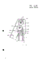
Fig. 1 is the hydro-extractor side view that optical scanning system of the present invention has been installed;
Fig. 2 is the planimetric map of Fig. 1 hydro-extractor;
Fig. 3 is a side plan view, utilizes a catoptron that groove arranged can finish the color separation of light on it;
Fig. 4 produces the optical schematic diagram that accurately is parallel to this bundle reflection of light mirror position of scanning samples;
Fig. 5 is the folded optical path synoptic diagram that is used for Fig. 1 sample, has represented the resolution that this optical system provides;
Fig. 6 is the partial sectional view of catoptron rotating mechanism.
Referring to Fig. 1 and Fig. 2, represent a what is called " ultracentrifuge ", represented that simply a motor MTR makes rotor R around axle A rotation, and be at a high speed.Rotor R is common with 100,000 rev/mins of rotations.Those skilled in the art all knows, will carry out centrifugal treating in a vacuum for fear of air resistance.
Sample is placed in the S1 of sample chamber, and there are roof window 20 and end window 22 in this chamber, and these windows allow the light that is parallel to the rotor R shaft axis pass through.When centrifugal process dynamically took place, light was by these corresponding windows, just realized the method that layering detects to the sample stratiform on the sample that the method by the present invention's instruction that impinges upon forms.
As for the illumination aspect, there is a lamp L outwards luminous among the lens barrel T along the rectangular pyramid body, and shine on the mirror M, light reflects downwards from mirror M, by folding lens barrel T1 that comes and the window 20 and 22 by sample chamber S1 on the rotor R, see through after these windows illumination and be mapped to a detector D and go up (see figure 2).To describe below, detector is a mobile slit, and this slit moves in sample radical length scope.
The power that hydro-extractor produces is generally within 5000 to 500,000 gravity field scope.The objective of the invention is to, when centrifugal process continues, directly detect the dynamic process that forms the stratiform structural stratification.Obviously, as long as the centrifugal process of detected sample one stops, will thoroughly destroy that result who attempts to detect.Specifically, the layering that can occur under powerful gravitational field in case remove this big gravitational field, tends to disappear in the mode of diffusion.
Next to determine some planes.The structure of optical system just can be studied once determining in these planes.
When using the hierarchy of optical means study sample, at first to lay sample at sample spot P place routinely, sample spot P arranges along the direction of radius 26 from the rotation of hydro-extractor.
The radius 26 that this sample plane comprises rotating shaft axis A and extends by sample spot from this axis, this sample plane is the plane that light collimates, the plane that the plane of Fig. 4 comes to this.
Also it should be noted that, perpendicular to the plane of this sample plane.This plane is one and disperses face, and the color separation of light takes place along this plane, and light does not collimate in dispersing face.This disperses face is plane shown in Figure 3.
Enumerated after these corresponding planes, just can describe the function of the special-purpose optical system of the present invention.These functions at first comprise the collimation of light, to realize the accurate detection along the layering of sample plane stratiform.Next is the color separation of light being discussed dispersing on the face.With reference to figure 5 resolution characteristics of the present invention will be discussed at last.
Referring to Fig. 3, stroboscopic light source L passes and is preferably 1mm or less than the aperture 28 of 1mm diameter.Light 40 from light source shines on the mirror M by corresponding tubular type diaphragm 30 and 32.
Referring to Fig. 4, the reader is appreciated that unshowned light source C.Among Fig. 4, light 40 sees through sample 50 and detector slit 52 by the mirror M reflection downwards, shines on the detector D, will be understood that slit 52 scans below sample 50.In this scanning, slit is parallel to rotating shaft A and perpendicular to the sample plane of Fig. 4, it can accurately detect the layering of layer structure.
In the sample plane of Fig. 4, expressing mirror M is a given cylindroid with respect to light source L.Selecting of this cylindroid will make light 40 collimate along the light path of the rotating shaft A that is parallel to rotor R is strict in Fig. 4 plane.So the stratiform layering that any sediment is told, as layer band B, collimated ray 40 is all accurately parallel with it, and by this layer band B.
In order to produce collimated ray, mirror M is shaped along an axis.And along another axis, this catoptron has another different curvature and unequal-interval delineation line is arranged, so that when inclined mirror, promptly produces the change of light color.
Such groove is known.United States Patent (USP) 3,909,134 referring to the people such as Pleuchard that announced on September 30th, 1975.The prior art relevant with such mirror structure, in the people's such as Pleuchard that announce on January 6th, 1976 the United States Patent (USP) 3930728, on March 20th, 1973 people such as Laude that the United States Patent (USP) announced was announced at March 2 in 3721487,1976 United States Patent (USP) 3,942, in 048, and all can find in the United States Patent (USP) 3628849 of the Flamand that announced on Dec 21st, 1971.
Wavelength for a change, grating approximately will change 30 ° of angles from the position perpendicular to light source.But regardless of the corner of grating, the effective curvature that is used to collimate is constant.
The reader it will be appreciated that illustrated mirror group is best.Other mirror group of collimated light on sample plane also is available.For example use lens and arrangement of mirrors.The route that slit 52 is pointed out along double-head arrow 54 moves around above detector D.As the United States Patent (USP) 3,712 that on January 23rd, 1973 announced, 724Cohen is described, will detect the variation that receives light in this moving.
Some Numerical examples is useful.What be particularly useful is that light source L is typical stroboscopic xenon light source, exports in 20 kilowatts of scopes at the light source in a flash of stroboscopic.
At sample chamber S
1In, the layer band B in the sample 50 is opaque layering basically, and light a large amount of decay can occur during by such opaque layer, and light decrement is about 10 altogether
17Magnitude, the decay of light is approximately 10 in sample
3Magnitude.
Refer back to Fig. 3 again, be preferably in and adopt a plurality of optical frequency bands in the scanning of the sample 50 among the sample S1, as being scanned by the protein of layering in to hydro-extractor 200 to 800 millimicrons or higher (this scope is the ultraviolet portion and the visible light part of spectrum).According to the present invention, in the plane of Fig. 4, mirror M has the curved surface of unequal-interval groove.Groove extends direction as shown in arrow 62 on the inside and outside direction in this plane as shown in Figure 3.Catoptron is around axis 60 rotation, and bandwidth that can 5 millimicrons scans sample 50.The reader should be clear, and sweep bandwidth or scanning bandpass width in fact are to be determined by the radiation solid angle of catoptron, and window 20,22 is as shown in Figure 3 and Figure 4 passed in this radiation.
Such scanning has its exhausted yarn part.Specifically, by the plane of the parallel light of color separation in layer band B, and in this plane, as shown in Figure 4.Such arrangement makes layer band B and the surface is all illuminated accordingly.The light of this irradiation is about ten times of the obtainable directional light of Fig. 3 and Fig. 4 two planes.Be only limited to the way of the plane of Fig. 4 being carried out optical alignment owing to adopt, and allow monochromatic light pass the layer band B on Fig. 3 plane, the light that then surpasses ten times will shine sample S
1In layer band B.
Referring to Fig. 5, represented the optical schematic diagram of native system, this principle has illustrated that folded optical path length among Fig. 3 and Fig. 4 is to the influence of sample layer band resolution.
Apart from x
1Indication lamp L and sample S
1Between the effective length of light path.It equals about 33cm.
Equally, apart from x
2Be slit 52 and sample S
1Between distance, this x
2Approximately be 2cm.Can find out light path x
1Compare x
2Much longer.Therefore layering B will be detected with high resolution in slit 52.Here have:
Emphaticallyed point out,, rotate mirror M in order to obtain multiple monochromatic light clearly.The device of realizing this rotation as shown in Figure 6.
See Fig. 6, expressed near the optical tubes the catoptron among Fig. 3 and Fig. 4 at this.Here the plane of representing catoptron is identical with Fig. 4's.
Specifically, light is upwards by lens barrel T.The light on being mapped to catoptron, all blocked (see figure 1) by shadow shield from all other light of light source L light beam.Light reflects downwards from mirror M, by lens barrel T
1Be mapped on the sample of the sample chamber that rotating putting.
Catoptron rotates around pivot 102.Drive catoptron by the gear series that comprises gear 103 and 104, this gear series also comprises reduction gearing 105,106 and idle pulley 107, and this idle pulley is at last by rack drives.Obviously, tooth bar 108 to the direction moving linearly of backreflection mirror, make mirror M obtain good adjustment and accurate the rotation.Because catoptron always can reflect directional light, so the variation of mirror angle only influences the color of place, rotary sample chamber light.
The reader should be understood that the ability with rapid change light color just can promptly adjust in the sample chamber color of the light on the layered material of wanting tested.So when each different radii by the sample chamber of photodetector, carry out optimal detection, can promptly change the monochromatic color of being taked for stratiform layering to the variable density told.
Yet.The component that those are heavier, particularly some salt has different refractive indexes.In this case, must there be certain angular breadth to make slit 52 receive the light of these layers band.
In view of the above, the have an appointment effective width of 0.1mm of slit 52, and leave at interval, thereby the positive and negative 2 ° of angles of vertically having looked from the sample aspect with respect to the effective surface of detector D.Because adopt this technology, the refractive index light that sample reflected inequality can be received, all diffused lights beyond this angle then shine less than on the detector.
Claims (2)
1, a kind of centrifuge combination system to sample centrifugal treating and then formation layering, comprise: a centrifugal rotor that rotates around turning axle, the sample chamber that has a rotating shaft with described rotor to separate on the described rotor, described sample chamber are being placed described sample and are being had first and second windows to see through the light that is parallel to described sample; The described sample chamber of irradiation is to detect the light source of described sample layering, and the light of described light source incides in the plane of described rotor and described sample formation; The detector that the light that sees through described sample is detected, can observe described layering, the system is characterized in that: limit the device of light path and rotate the device of described catoptron, limit light path device and comprise a toroidal reflectors that two radius-of-curvature are arranged, one of them described radius-of-curvature direction only is used for collimated light is limited in the described sample plane, has another radius-of-curvature direction of groove that the light of different frequency is come out from described mirror reflects with different angles; Rotate the device of described catoptron, be used to rotate described catoptron, correspondingly described first curvature radius direction is used to select the light frequency to described sample scanning under the situation of keeping parallelism rayed sample.
2,, it is characterized in that described catoptron is depicted the diffraction groove that is parallel to described sample face according to the combined system of claim 1.
Applications Claiming Priority (2)
| Application Number | Priority Date | Filing Date | Title |
|---|---|---|---|
| US115023 | 1987-10-29 | ||
| US07/115,023 US4830493A (en) | 1987-10-29 | 1987-10-29 | UV scanning system for centrifuge |
Publications (2)
| Publication Number | Publication Date |
|---|---|
| CN1039123A CN1039123A (en) | 1990-01-24 |
| CN1011554B true CN1011554B (en) | 1991-02-06 |
Family
ID=22358870
Family Applications (1)
| Application Number | Title | Priority Date | Filing Date |
|---|---|---|---|
| CN88109257.6A Expired CN1011554B (en) | 1987-10-29 | 1988-10-29 | Ultraviolet scanning system for centrifuger |
Country Status (8)
| Country | Link |
|---|---|
| US (1) | US4830493A (en) |
| EP (1) | EP0340279B1 (en) |
| JP (1) | JPH0742121Y2 (en) |
| CN (1) | CN1011554B (en) |
| CA (1) | CA1295031C (en) |
| DE (1) | DE3874125T2 (en) |
| HU (1) | HU206771B (en) |
| WO (1) | WO1989003986A1 (en) |
Families Citing this family (26)
| Publication number | Priority date | Publication date | Assignee | Title |
|---|---|---|---|---|
| US4921350A (en) * | 1989-02-10 | 1990-05-01 | Beckman Instruments, Inc. | Monochromator second order subtraction method |
| US5123740A (en) * | 1991-01-15 | 1992-06-23 | Beckman Instruments, Inc. | Stray light trap in a monochrometer |
| GB9302673D0 (en) * | 1993-02-11 | 1993-03-24 | Haematest Limited | Apparatus for analysing blood and other samples |
| US5563333A (en) * | 1995-01-20 | 1996-10-08 | Haines; Hiemi K. | Method and apparatus for core flooding studies |
| US7173551B2 (en) | 2000-12-21 | 2007-02-06 | Quellan, Inc. | Increasing data throughput in optical fiber transmission systems |
| US7307569B2 (en) * | 2001-03-29 | 2007-12-11 | Quellan, Inc. | Increasing data throughput in optical fiber transmission systems |
| US7149256B2 (en) | 2001-03-29 | 2006-12-12 | Quellan, Inc. | Multilevel pulse position modulation for efficient fiber optic communication |
| DE60238602D1 (en) * | 2001-04-04 | 2011-01-27 | Quellan Inc | METHOD AND SYSTEM FOR DECODING MULTI-LEVEL SIGNALS |
| US20030030873A1 (en) * | 2001-05-09 | 2003-02-13 | Quellan, Inc. | High-speed adjustable multilevel light modulation |
| AU2003211094A1 (en) * | 2002-02-15 | 2003-09-09 | Quellan, Inc. | Multi-level signal clock recovery technique |
| US6816101B2 (en) * | 2002-03-08 | 2004-11-09 | Quelian, Inc. | High-speed analog-to-digital converter using a unique gray code |
| WO2003092237A1 (en) * | 2002-04-23 | 2003-11-06 | Quellan, Inc. | Combined ask/dpsk modulation system |
| JP2004013681A (en) * | 2002-06-10 | 2004-01-15 | Bosu & K Consulting Kk | Name card information managing system |
| AU2003256569A1 (en) * | 2002-07-15 | 2004-02-02 | Quellan, Inc. | Adaptive noise filtering and equalization |
| US7934144B2 (en) * | 2002-11-12 | 2011-04-26 | Quellan, Inc. | High-speed analog-to-digital conversion with improved robustness to timing uncertainty |
| US7804760B2 (en) * | 2003-08-07 | 2010-09-28 | Quellan, Inc. | Method and system for signal emulation |
| GB2421674B (en) * | 2003-08-07 | 2006-11-15 | Quellan Inc | Method and system for crosstalk cancellation |
| US7123676B2 (en) * | 2003-11-17 | 2006-10-17 | Quellan, Inc. | Method and system for antenna interference cancellation |
| US7616700B2 (en) * | 2003-12-22 | 2009-11-10 | Quellan, Inc. | Method and system for slicing a communication signal |
| US7209230B2 (en) | 2004-06-18 | 2007-04-24 | Luckoff Display Corporation | Hand-held spectra-reflectometer |
| US7522883B2 (en) | 2004-12-14 | 2009-04-21 | Quellan, Inc. | Method and system for reducing signal interference |
| US7725079B2 (en) * | 2004-12-14 | 2010-05-25 | Quellan, Inc. | Method and system for automatic control in an interference cancellation device |
| US7502109B2 (en) * | 2005-05-17 | 2009-03-10 | Honeywell International Inc. | Optical micro-spectrometer |
| US7233394B2 (en) | 2005-06-20 | 2007-06-19 | Luckoff Display Corporation | Compact spectrometer |
| DE112007001045B4 (en) * | 2006-04-26 | 2019-05-16 | Intersil Americas LLC | Method and system for reducing radiation emissions from a communication channel |
| CN116899767A (en) * | 2022-04-18 | 2023-10-20 | 汾沃有限公司 | Interface monitoring assembly, fluid separation device and method for separating fluid |
Family Cites Families (12)
| Publication number | Priority date | Publication date | Assignee | Title |
|---|---|---|---|---|
| FR2036613A5 (en) * | 1969-03-26 | 1970-12-24 | Jobin Et G Yvon | |
| GB1256269A (en) * | 1969-06-27 | 1971-12-08 | Mse Holdings Ltd | Centrifuge |
| FR2055891A5 (en) * | 1969-08-05 | 1971-05-14 | Anvar | |
| FR2096982B1 (en) * | 1970-07-23 | 1974-06-14 | Jobin & Yvon | |
| US3807874A (en) * | 1972-03-31 | 1974-04-30 | Beckman Instruments Inc | Optical system for centrifuges |
| US3973850A (en) * | 1972-04-21 | 1976-08-10 | Agence Nationale De Valorisation De La Recherche (Anvar) | Focalization process of spherical concave diffraction gratings |
| FR2239674B1 (en) * | 1973-08-03 | 1976-04-30 | Jobin & Yvon | |
| FR2240445B2 (en) * | 1973-08-06 | 1976-05-07 | Jobin & Yvon | |
| FR2271586B1 (en) * | 1973-11-29 | 1978-03-24 | Instruments Sa | |
| US4285596A (en) * | 1977-08-16 | 1981-08-25 | Neotec Corporation | Holographic diffraction grating system for rapid scan spectral analysis |
| CH647598A5 (en) * | 1980-01-14 | 1985-01-31 | Haakon Trygve Jun Magnussen | Spectral photometer for carrying out a spectral analysis |
| JPS5761934A (en) * | 1980-09-30 | 1982-04-14 | Hitachi Koki Co Ltd | Scanning apparatus of light absorption of ultracentrifuge in common use of separation and analysis |
-
1987
- 1987-10-29 US US07/115,023 patent/US4830493A/en not_active Expired - Lifetime
-
1988
- 1988-10-13 CA CA000580040A patent/CA1295031C/en not_active Expired - Lifetime
- 1988-10-20 HU HU886712A patent/HU206771B/en not_active IP Right Cessation
- 1988-10-20 JP JP1990600002U patent/JPH0742121Y2/en not_active Expired - Lifetime
- 1988-10-20 DE DE8888909862T patent/DE3874125T2/en not_active Expired - Fee Related
- 1988-10-20 WO PCT/US1988/003683 patent/WO1989003986A1/en active IP Right Grant
- 1988-10-20 EP EP88909862A patent/EP0340279B1/en not_active Expired
- 1988-10-29 CN CN88109257.6A patent/CN1011554B/en not_active Expired
Also Published As
| Publication number | Publication date |
|---|---|
| DE3874125D1 (en) | 1992-10-01 |
| CA1295031C (en) | 1992-01-28 |
| EP0340279A1 (en) | 1989-11-08 |
| HU206771B (en) | 1992-12-28 |
| EP0340279B1 (en) | 1992-08-26 |
| DE3874125T2 (en) | 1993-04-08 |
| JPH0742121Y2 (en) | 1995-09-27 |
| JPH02500028U (en) | 1990-07-05 |
| HU886712D0 (en) | 1990-09-28 |
| US4830493A (en) | 1989-05-16 |
| CN1039123A (en) | 1990-01-24 |
| HUT53736A (en) | 1990-11-28 |
| WO1989003986A1 (en) | 1989-05-05 |
Similar Documents
| Publication | Publication Date | Title |
|---|---|---|
| CN1011554B (en) | Ultraviolet scanning system for centrifuger | |
| US5127729A (en) | Method and apparatus for guiding and collecting light in photometry or the like | |
| US4703182A (en) | Arrangement for fluorescence-optical measurement of concentrations of substances contained in a sample | |
| EP0127418B1 (en) | Equipment for the measurement of fluorescence, turbidity, luminescence, or absorption | |
| AU576774B2 (en) | Optically based measurement of fluid parameters | |
| CN1643368A (en) | Method and apparatus for analysing liquids | |
| CN1409818A (en) | Compact spectrofluorometer | |
| US6714297B1 (en) | Light detecting optical device | |
| CN1752739A (en) | The spectrophotometer of quick measure spectrum | |
| US7209237B2 (en) | Optical system for analyzing multi-channel samples and multi-channel sample analyzer employing the same | |
| US6226083B1 (en) | Integrated-optic spectrometer and method | |
| CN105911036A (en) | Miniature fluorescence spectrum detection device based on hollow Bragg fibers | |
| US5309216A (en) | Method of and an apparatus for determining particle size distributions by measuring the spectral light extinction during sedimentation | |
| Ma et al. | Optical-fiber Raman probe with low background interference by spatial optimization | |
| CN1719288A (en) | Multi frequency acute angle space light filter | |
| CN88100938A (en) | The optical detecting method and the device thereof that on automatic analysing apparatus, carry out | |
| US5473438A (en) | Spectroscopic method and apparatus for measuring optical radiation | |
| US4921350A (en) | Monochromator second order subtraction method | |
| US4919537A (en) | UV scanning system for centrifuge | |
| CN2837834Y (en) | Spectrophotometer for quickly measuring spectrum | |
| CA2073344C (en) | Fluorescence assay apparatus | |
| CN1042777A (en) | The quality testing of lens surface | |
| Toriumi et al. | Variable‐angle ultraviolet total‐internal‐reflection fluorescence spectroscopy using a white excitation light source | |
| SU1659795A1 (en) | Photometer for scanning firmament | |
| SU1183934A1 (en) | Microscope |
Legal Events
| Date | Code | Title | Description |
|---|---|---|---|
| C06 | Publication | ||
| PB01 | Publication | ||
| C10 | Entry into substantive examination | ||
| SE01 | Entry into force of request for substantive examination | ||
| C13 | Decision | ||
| GR02 | Examined patent application | ||
| C14 | Grant of patent or utility model | ||
| GR01 | Patent grant | ||
| C19 | Lapse of patent right due to non-payment of the annual fee | ||
| CF01 | Termination of patent right due to non-payment of annual fee |