CN101099877A - A medical guide wire, an assembly body of the same medical guide wire and microcatheter, an assembly body of the same medical guide wire, a balloon catheter and a guiding catheter - Google Patents
A medical guide wire, an assembly body of the same medical guide wire and microcatheter, an assembly body of the same medical guide wire, a balloon catheter and a guiding catheter Download PDFInfo
- Publication number
- CN101099877A CN101099877A CNA2007101040519A CN200710104051A CN101099877A CN 101099877 A CN101099877 A CN 101099877A CN A2007101040519 A CNA2007101040519 A CN A2007101040519A CN 200710104051 A CN200710104051 A CN 200710104051A CN 101099877 A CN101099877 A CN 101099877A
- Authority
- CN
- China
- Prior art keywords
- helical spring
- spring body
- guide wire
- medical guide
- radiopaque
- Prior art date
- Legal status (The legal status is an assumption and is not a legal conclusion. Google has not performed a legal analysis and makes no representation as to the accuracy of the status listed.)
- Pending
Links
Images


Classifications
-
- A—HUMAN NECESSITIES
- A61—MEDICAL OR VETERINARY SCIENCE; HYGIENE
- A61M—DEVICES FOR INTRODUCING MEDIA INTO, OR ONTO, THE BODY; DEVICES FOR TRANSDUCING BODY MEDIA OR FOR TAKING MEDIA FROM THE BODY; DEVICES FOR PRODUCING OR ENDING SLEEP OR STUPOR
- A61M25/00—Catheters; Hollow probes
- A61M25/01—Introducing, guiding, advancing, emplacing or holding catheters
- A61M25/09—Guide wires
-
- A—HUMAN NECESSITIES
- A61—MEDICAL OR VETERINARY SCIENCE; HYGIENE
- A61M—DEVICES FOR INTRODUCING MEDIA INTO, OR ONTO, THE BODY; DEVICES FOR TRANSDUCING BODY MEDIA OR FOR TAKING MEDIA FROM THE BODY; DEVICES FOR PRODUCING OR ENDING SLEEP OR STUPOR
- A61M25/00—Catheters; Hollow probes
- A61M25/01—Introducing, guiding, advancing, emplacing or holding catheters
-
- A—HUMAN NECESSITIES
- A61—MEDICAL OR VETERINARY SCIENCE; HYGIENE
- A61M—DEVICES FOR INTRODUCING MEDIA INTO, OR ONTO, THE BODY; DEVICES FOR TRANSDUCING BODY MEDIA OR FOR TAKING MEDIA FROM THE BODY; DEVICES FOR PRODUCING OR ENDING SLEEP OR STUPOR
- A61M25/00—Catheters; Hollow probes
- A61M25/0043—Catheters; Hollow probes characterised by structural features
- A61M25/0045—Catheters; Hollow probes characterised by structural features multi-layered, e.g. coated
- A61M2025/0046—Coatings for improving slidability
-
- A—HUMAN NECESSITIES
- A61—MEDICAL OR VETERINARY SCIENCE; HYGIENE
- A61M—DEVICES FOR INTRODUCING MEDIA INTO, OR ONTO, THE BODY; DEVICES FOR TRANSDUCING BODY MEDIA OR FOR TAKING MEDIA FROM THE BODY; DEVICES FOR PRODUCING OR ENDING SLEEP OR STUPOR
- A61M25/00—Catheters; Hollow probes
- A61M25/01—Introducing, guiding, advancing, emplacing or holding catheters
- A61M25/09—Guide wires
- A61M2025/09058—Basic structures of guide wires
- A61M2025/09083—Basic structures of guide wires having a coil around a core
- A61M2025/09091—Basic structures of guide wires having a coil around a core where a sheath surrounds the coil at the distal part
-
- A—HUMAN NECESSITIES
- A61—MEDICAL OR VETERINARY SCIENCE; HYGIENE
- A61M—DEVICES FOR INTRODUCING MEDIA INTO, OR ONTO, THE BODY; DEVICES FOR TRANSDUCING BODY MEDIA OR FOR TAKING MEDIA FROM THE BODY; DEVICES FOR PRODUCING OR ENDING SLEEP OR STUPOR
- A61M25/00—Catheters; Hollow probes
- A61M25/01—Introducing, guiding, advancing, emplacing or holding catheters
- A61M25/09—Guide wires
- A61M2025/09166—Guide wires having radio-opaque features
Abstract
A medical guide wire ( 1 ) has a helical spring body ( 3 ), a distal end portion of which has a radiopaque helical portion ( 31 ), and an elongate core ( 2 ) placed within the helical spring body ( 3 ). The elongate core ( 2 ) has a distal end portion ( 21 ) diametrically thinned and having a proximal end portion ( 22 ) diametrically thickened. A securement portion ( 10 ) is provided in which the distal end of the helical spring body ( 3 ) and the distal end of the elongate core ( 2 ) are air-tightly bonded. A floatage chamber ( 5 ) is formed within the radiopaque helical portion ( 31 ). A synthetic resin layer ( 4 ) coated on an outer surface of the helical spring body ( 3 ) forms a cylindrical film ( 43 ) at a clearance (C) between neighboring coil lines of the helical spring body ( 3 ) in a condition that an outer diameter of the cylindrical film ( 43 ) is smaller than that of the helical spring body ( 3 ) when expanding the helical spring body ( 3 ) in the moistened condition, thus enabling an operator to a deep insertion against a blood vessel due to a buoyance and an increased pressure resistance caused by blood streams.
Description
Technical field
The present invention relates to a kind of improved medical lead, can make operator deeply be inserted into tortuous blood vessel, use blood flow best.
Background technology
When the human organ is especially treated diagnosis such as blood vessel, digestive tract, urethra etc., be necessary before conduit is inserted blood vessel, guide line to be inserted into destination.In order successfully guide line to be inserted tortuous crooked blood vessel (being difficult to the zone of arrival), various technology have been proposed at present.
Japanese Laid-Open Patent Application has disclosed a kind of guide line 2000-135289 number by way of example, and it has the radiopaque spiral metal coil that is fixed on the elongated core distal portions.Be provided with plastic conduit with outer surface that centers on the spiral metal coil and the outer surface that when expanding, covers the metal spiral coil.Because the slickness of plastic conduit, this makes operator can realize good lubricating, and simultaneously, has reduced the thrombi that is deposited on the plastic conduit, makes that the thin far-end by elongated core is guaranteed good pushing away property when being inserted into blood vessel.
Japanese Laid-Open Patent Application 4-9162 has disclosed a kind ofly has flexibility and major part has inflexible guide line at distal portions.A kind of height radiopaque metal (as the high sensitivity comparison of X ray photography) inserts distal portions.Certain synthetic resin covers guide line, and presents lubricity when moistening, therefore because high-lubricity can provide operator with good maneuverability (push away and draw).
Japanese Utility Model is registered No. 2588582 and has been disclosed a kind of guide line, and wherein the radiopaque coil stationary is at the far-end of elongated core.Because the friction that proximal part reduces, hydrophilic layer and hydrophobic layer are coated on the guide line to realize good operability.
In the above prior art, do not have not only well to utilize the buoyancy in blood or the blood flow but also utilize the pressure drag between double-decker and difference in specific gravity in the blood flow and make operator can realize the notion of good maneuverability.
Therefore the objective of the invention is to overcome above shortcoming, and a kind of medical guide wire that can improve maneuverability by formation buoyancy cavity in the distal portions of helical spring part is provided, described distal portions is easy to sagging under the influence of gravity.
Another object of the present invention provides a kind of medical guide wire, when partly expanding with the gap between the winding wire that enlarges the helical spring part, helical spring can keep air close, and by utilizing pressure drag and difference in specific gravity between blood flow inner hydrophilic layer and the hydrophobic layer to strengthen forward propulsion.
Summary of the invention
According to the present invention, a kind of medical guide wire is provided, wherein be provided with the helical spring body, its far-end has the radiopaque spiral part of being made by the radiopaque material, and its near-end has the transmissive line spiral part of being made by the transmissive wire material.Elongated core is placed in the helical spring body, and has the distal portions of variation in diameter and the proximal part of diameter chap.The far-end of helical spring body and the far-end of elongated core link airtightly.Synthetic resin layer is coated on the outer surface of helical spring body airtightly along the circumference direction.Peripheral wall is arranged on the near-end of radiopaque spiral part airtightly helical spring body and elongated core are linked together.Buoyancy cavity is arranged in the radiopaque spiral part by sealed wall, synthetic resin layer and standing part, the wherein gastight binding of the far-end of the far-end of helical spring body and elongated chipware.Synthetic resin layer is lubricated under moisture state than under drying regime, wherein the gap location of synthetic resin layer between the adjacent lines astragal of helical spring body forms the cylindrical membrane cylindrical membrane, condition is the external diameter of the external diameter of cylindrical membrane cylindrical membrane less than helical spring body when the inflationary spiral spring body under wetness conditions, makes that gap between the adjacent lines astragal of helical spring body is the 50-100% of external diameter of the winding wire of helical spring body.The cylindrical membrane cylindrical membrane is between the mid diameter part of the inner surface of helical spring body and helical spring body, make the outer surface of helical spring body rise and fall to form jog, make adjacent windings line formation projection and cylindrical membrane cylindrical membrane be deformed into female, to strengthen forward propulsion owing to blood flow collides the pressure drag of projection generation and the spiral flow of the coil winding structure generation of helical spring body portion when the helical spring body is inserted blood vessel causes.
Because buoyancy cavity optionally is arranged on the far-end of the radiopaque spiral part of helical spring body, buoyancy cavity is because blood or blood flow are subjected to buoyancy, and is sagging under gravity effect with the distal portions that prevents the helical spring body.
This makes operator can keep distal portions the holding position in blood vessel of medical guide wire, to strengthen the navigability of medical guide wire.
Because the cylindrical membrane cylindrical membrane that under moisture state, forms by the expansion synthetic resin layer, it is intravital airtight to keep helical spring, and gas componant is overflowed in the bending of radiopaque spiral part during with the gap between the winding wire of widening helical spring part from the helical spring body.
Because the gap between the adjacent lines astragal of helical spring body is the 50-100% of helical spring body coil line external diameter, can keep the intravital airtight elastic-restoring force of helical spring to guarantee for example when the helical spring body reverses far-end in blood vessel, to produce owing to buoyancy cavity.This is because the cylindrical membrane cylindrical membrane has been filled the gap between the adjacent lines astragal of helical spring body.
When medical guide wire was inserted blood vessel, therefore the helical spring body made operator can insert blood vessel deeply because convexconcave part is subjected to pressure drag and spiral flow (forward propulsion).
According to a further aspect in the invention, utilized the elastic-restoring force that air pressure produced that when the radiopaque spiral part with the helical spring body bends to bending position, increases in the buoyancy cavity, and pressed the primary quantity level in the buoyancy cavity that is reduced to from bending position release radiopaque spiral part seasonal epidemic pathogens.
Because buoyancy cavity optionally is arranged on and is easy to be subjected in the radiopaque spiral part of plastic deformation, can utilize the elastic-restoring force of buoyancy cavity and significantly reduce the sag of chain and the plastic deformation of radiopaque spiral part.This makes operator can stably keep the initial favourable structure of medical guide wire distal portions.
According to a further aspect in the invention, synthetic resin layer is made by the mixture of hydrophilic polymer and hydrophobic polymer.The proportion of synthetic resin layer reduces laterally from the inboard of synthetic resin layer when moistening.
Except hydrophilic polymer and the simple blended mixture of hydrophobic polymer, hydrophilic polymer can be added in the mixture of hydrophobic polymer and binder polymer to form another kind of mixture.Perhaps, hydrophilic polymer is mixed with hydrophobic polymer, wherein add plasticizer to form another kind of again mixture.Perhaps, hydrophilic polymer can mix with hydrophobic polymer, and the mixture that wherein adds binder polymer and plasticizer is to form another mixture again.
Because the weight ratio of hydrophilic polymer increases continuously laterally from the inboard that the synthetic resin layer volume increases gradually, the Outboard Sections of hydrophilic polymer occupies most of synthetic resin layer, therefore can produce the lightweight guide line, feasible Outboard Sections owing to hydrophilic polymer has less proportion and guarantees high buoyance lift.
According to a further aspect in the invention, synthetic resin layer has first hydrophobic layer as solid layer on the helical spring body, and is provided with second hydrophilic layer as fluid layer on the outer surface of first hydrophobic layer.The proportion of second hydrophilic layer is less than first hydrophobic layer when moistening.
Because second hydrophilic layer (proportion is less) has occupied the major part of synthetic resin layer, so the lightweight guide line that can obtain to have the high buoyance lift characteristic of guaranteeing.
According to a further aspect in the invention, the helical spring body has the radiopaque spiral part of being made by the radiopaque material, and its springback capacity is less than the springback capacity of stainless steel silk.
Under the influence of elastic-restoring force, more than be provided with and reduce the plastic deformation that the radiopaque spiral part is subjected to, although the radiopaque spiral part has the material of the plastic deformation of being easy to.
According to a further aspect in the invention, the helical spring body has the radiopaque spiral part of being made by the radiopaque material, and its springback capacity is less than the springback capacity of stainless steel silk.Transmissive line spiral part is made by stainless steel silk, and the external diameter of radiopaque spiral part is less than the external diameter of transmissive line spiral part.
As mentioned above, elastic-restoring force reduced the plastic deformation that the radiopaque spiral part is subjected to, although the radiopaque spiral part is easy to plastic deformation.
According to a further aspect in the invention, the helical spring body forms to form the tinsel member by the radiopaque material being connected to the transmissive wire material, and described member length direction stretches so that variation in diameter and spiral twine to form helical coil structure.
Before spiral twined radiopaque material and transmissive wire material, radiopaque material and transmissive wire material linked into an integrated entity and are extended into variation in diameter by for example welding procedure linearity.
This avoided in the prior art structure two spiral windings are partly contacted banded welding or brazing program help to produce the lightweight guide line with high buoyance lift performance like this.
According to a further aspect in the invention, the helical spring body has many filaments, and wherein at least one distal portions at the helical spring body comprises the radiopaque material.
Compare with the unicoil silk structure that forms conventional helical spring body with the winding of single metal wire spiral, helical spring body according to the present invention can keep the cylindrical membrane cylindrical membrane of the synthetic resin layer of gap location between the many filaments, even and become in the direction of pull stretching, extension cylindrical membrane cylindrical membrane is broken in helical spring body overbending.
According to a further aspect of the invention, buoyancy cavity seals the foams of discrete foaming structure.
The foams of sealing prevent elongated core and the plastic deformation of helical spring body effectively, to strengthen elastic-restoring force.
According to a further aspect in the invention, buoyancy cavity seals spherical foam beads, and its specific gravity range is 0.06-0.5.
The spherical foam pearl has reduced the contact area between the adjacent foam beads, has therefore produced cavity area, helps to form buoyancy cavity on the function to help to strengthen the buoyance lift performance.
According to a further aspect in the invention, the assembly of a kind of microguide and medical guide wire is provided, wherein the external diameter of medical guide wire is about 0.2032-0.254mm (0.008-0.010 inch), and the internal diameter of microguide is about 0.280-0.80mm (0.0110-0.0315 inch).
Although medical guide wire is variation in diameter in assembly, because therefore the auxiliary promotion that can increase medical guide wire of microguide makes operator medical guide wire can be inserted blood vessel deeply.Thereby can meet to patient's low intrusion with alleviate patient when treatment is handled the requirement of burden.
According to a further aspect of the invention, provide a kind of guide catheter, balloon catheter and the assembly of medical guide wire, medical guide wire inserts described guide catheter, balloon catheter is guided by guide catheter simultaneously.The external diameter of medical guide wire is about 0.2032-0.254mm (0.008-0.010 inch), and the internal diameter of balloon catheter is about the about 1.7-2.0mm of internal diameter (0.067-0.079 inch) of 0.38-0.90mm (0.015-0.032 inch) and guide catheter.
This assembly can make operator by means of the buoyancy and the pressure drag of buoyancy cavity distal portions be floated on the blood flow, so that medical guide wire is inserted blood vessel deeply.This can make balloon catheter and guide catheter attenuate respectively, with meet to patient's low intrusion with alleviate patient when treatment is handled the requirement of burden.
Description of drawings
Preferred embodiment of the present invention has been shown in the accompanying drawing, wherein:
Fig. 1 is the side view according to the first embodiment of the invention medical guide wire;
Fig. 2 is the latitude direction cross section that the line A-A along Fig. 1 obtains;
Fig. 3 is the side view of elongated core;
Fig. 4 is the plane graph of elongated core;
Fig. 5 is the axonometric chart of multistage flat part;
Fig. 6 and 7 is longitudinal cross-section figure of medical guide wire distal portions;
Fig. 8 is the sketch map shown in when the distal portions of medical guide wire is crooked;
Fig. 9 is that the distal portions when medical guide wire is pulled and side view when stretching;
Expanded what sketch map of Figure 10 and 11 sweep that is explanations of illustrating when the distal portions reversing of medical guide wire;
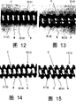
Figure 12 to 15 is that the photo that illustrates is how to form the column type thin film to reveal between the helical spring winding wire partly;
Figure 16 is how the explanation medical guide wire inserts view coronarius;
Figure 17 be the explanation blood flow how with the view of the lobe phase-splitting effect of helical spring part;
Figure 18 is the side view according to the medical guide wire distal portions of second embodiment of the invention;
Figure 19 is the axonometric chart according to the medical guide wire of third embodiment of the invention;
How crooked Figure 20 show unicoil line structure plane graph, and wherein single single line twines spirally to form the roughly spring body of spiral;
How crooked Figure 21 show the helical spring part made by many one metal wires plane graph;
Figure 22 and 23 is longitdinal cross-section diagrams of the distal portions of the medical guide wire of the 4th and the 5th embodiment according to the present invention;
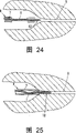
Figure 24 and 25 shows the sketch map how the explanation medical guide wire inserts high occlusion areas by means of medical guide wire and microtubular according to sixth embodiment of the invention;
Figure 26 is the side view of the elongated core of modification according to the present invention;
Figure 27 is the right view of the elongated core of modification according to the present invention;
Figure 28 is the axonometric chart of the multistage end of modification according to the present invention;
Figure 29 is the side view of the medical guide wire of another modification according to the present invention;
Figure 30 is the latitude direction cross-sectional view that the line B-B along Figure 29 obtains;
Figure 31 is the latitude direction cross-sectional view that the line C-C along Figure 29 obtains;
Figure 32 is the side view of the medical guide wire of another modification again according to the present invention;
The specific embodiment
In order more specifically to describe these embodiment, describe the structure of medical guide wire and helical spring body in detail with reference to accompanying drawing.
In the following explanation of illustrated embodiment, identical label is used for the structure of same type.
Fig. 1-17 structurally shows the medical guide wire according to first embodiment of the invention, and medical guide wire 1 is used for the treatment of occlusion areas coronarius to be handled.
In this case, the distal side of medical guide wire 1 is represented on the right side of figure, and the left side of figure represents the proximal lateral (rear end side) of medical guide wire 1, unless after this explanation is arranged in addition.
As shown in Figure 5 from the nearside of elongated core 2 to the distally, distal portions 21 has violent sloping portion 23, moderate sloping portion 24, cylindrical section 25, slight slope part 26 and multistage flat part 27 continuously.
Multistage flat part 27 has first section 27a, second section 27b and the 3rd section 27c from distal-to-proximal step portion 27A, the 27B of passing.The thickness of first section 27a of portion foremost that is arranged in elongated core 2 is less than the thickness of arbitrary section of 27b and 27c.The thickness of the second section 27b that is right after first section 27a back is a bit larger tham first section 27a.The thickness of the 3rd section 27c that is right after second section 27b back is a bit larger tham second section 27b.
When making multistage flat part 27 crooked, each section 27a, 27b, 27c demonstrate the radius of curvature that increases step by step in proper order with this.
Multistage flat part 27 makes and might make distal portions 21 flexural deformations in than close limit, therefore makes operator closely to follow distal portions 21 along the zigzag path in angiostenosis zone when distal portions 21 is inserted blood vessel.
As example, the thickness of each section 27a, 27b, 27c can be followed successively by 0.040mm, 0.050mm and 0.063mm.
At each section 27a, 27b, the latitudinal cross-sectional area of 27c along its length direction under the basic situation uniformly, when distal portions 21 being pressed between the briquetting (not shown) of upper and lower, elongated core 2 basically with far-end 21 section aligned parallel with stamper mould.This makes that the fine dimension of each section 27a, 27b, 27c is highly precisely stable, and has prolonged the life-span of stamper mould.
The front side of helical spring body 3 has radiopaque spiral part 31 (the about 30mm of length) of being made by platinum etc., and the rear side of helical spring body 3 has the radioparent spiral part of being made by rustless steel etc. 32 (the about 270mm of length).
Except the platinum filament that is applied to helical spring body 3 as the radiopaque material, also can use spun gold, filamentary silver or tungsten filament.As the transmissive wire material, use stainless steel silk from biocompatible viewpoint.
Radiopaque material such as platinum filament is easy to plastic deformation, has the springback capacity less than stainless steel silk.
Line tinsel (external diameter 0.072mm) by coil coiling loop construction (external diameter 0.355mm) forms helical spring body 3, and the external diameter of radiopaque spiral part 31 becomes than the little 0.02mm of external diameter of transmissive line spiral part 32.This means that helical spring body 3 is along with diameter reduces (being tapered) gradually near the place ahead.Radiopaque spiral part 31 is gapped C between the winding wire W of helical spring body 3.The width of clearance C is about the 10-30% of winding wire W external diameter to give radiopaque spiral part 31 with good flexibility.
The far-end 3 of helical spring body 3 and the far-end of elongated core 2 link airtightly at standing part (welding portion) 10, by using spherical stannum grain (stannum bead), brazing solder etc. without any the slit.The near-end 34 of helical spring body 3 firmly fixes on the part 23 of rapid inclination by welding procedure.Synthetic resin layer 4 extends to the proximal part 22 of elongated core from the outer surface of helical spring body 3.
When getting wet, second hydrophilic layer 42 has lubricity.First hydrophobic layer 41 forms hydrophobic coating by polyurethane, amino-polyether block, polyethylene, polyamide, fluorochemical polymers etc.Second hydrophilic layer 42 forms hydrophilic coating by polyvinylpyrrolidone, ethyl copolymerization maleic anhydride (maleic anhydride ethylestercopolymer), poly(ethylene oxide) etc.
The proportion of second hydrophilic layer 42 is less than the proportion of first hydrophobic layer 41 when getting wet.
When first hydrophobic layer, 41 usefulness PTFE (politef, proportion 2.14-2.20) form, polyvinylpyrrolidone, ethyl copolymerization maleic anhydride or poly(ethylene oxide) (proportion approaches water basically) are coated to second hydrophilic layer 42.When first hydrophobic layer 41 by polyurethane (proportion 1.20-1.24) or polyethers (proportion: when 1.38) forming, polyvinylpyrrolidone (proportion approaches water basically) can be used for second hydrophilic layer 42.
First hydrophobic layer 41 and second hydrophilic layer 42 can be coated on the outer surface of helical spring body 3 successively, make the hydrophobic layer 41 of winning as inner overlay, as shown in Figure 6.
Perhaps can before being coated in second hydrophilic layer 42 on first hydrophobic layer 41, first hydrophobic layer 41 be coated on the whole surface of winding wire W, as shown in Figure 7.
Coupling part between radiopaque spiral part 31 and transmissive line spiral part 32 provides sealed wall 11 by welding procedure.Sealed wall 11 is attached to the near-end of radiopaque spiral part 31 on the elongated core 2 airtightly, the slit do not occur by spherical stannum grain (stannum bead), brazing solder etc.
The inner space of sealed wall 11 in standing part 10 and synthetic resin layer 4 limit radiopaque spiral part 31 hermetically is to form buoyancy cavity 5.
When helical spring body 3 extends when widening clearance C with at crooked medical guide wire 1 time, bending force makes synthetic resin layer 4 stretch to form cylindrical membrane cylindrical membrane 43 at the clearance C place, as shown in Figure 9.Stretch film 43 and make its external diameter be decreased to external diameter, and keep helical spring body 3 inner spaces airtight less than helical spring body 3.
As shown in Figure 8, radiopaque spiral part 31 from the far-end of radiopaque spiral part 31 in about 2-7mm scope one or the many places preform, make operator can be optionally insert with reference to the component of blood vessel.When helical spring body 3 was inserted the angiostenosis zone, because the blood vessel wall of contact blood vessel, insertion force flexibly made 3 distortion of helical spring body.
In this case, helical spring body 3 extends to widen clearance C, as shown in Figure 9.But synthetic resin layer 4 absorbs aqueous ingredients (water) with by moistening, and extends to form cylindrical membrane 43 continuously along clearance C.
That is, the outer surface of synthetic resin layer 4 rises and falls to form convexconcave part 6, makes bossing 61 be positioned at winding wire W place and recessed portion 62 is positioned at the clearance C place that cylindrical membrane cylindrical membrane 43 extends internally.
Generally speaking, coronary artery have about 2-4mm internal diameter and along with inwardly near and attenuate.When shown in Figure 10,11 helical spring body 3 being inserted coronary artery, helical spring body 3 reverses its distal portions at the blood vessel restricted area, even but this situation have also seldom.
By way of example, external diameter (d) when medical guide wire is 0.35mm as shown in figure 10, and internal diameter coronarius (D) is when being 2.0mm, and poor (Δ s) between the outside arc length (L) of helical spring body 3 and the inner arc length (m) determines as follows at sweep:
Δs=L-m
=(π×2.0×1/2)-(π×1.3×1/2)1.099mm
This means inner arc length (m:2.04mm) thus becoming 3.139mm produces 1.53 prolongation ratio.This expression helical spring body 3 results extend about 50%.
When internal diameter coronarius (D) when being 1.4mm, poor (Δ s) determines as follows at sweep as shown in figure 11:
Δs=L-m
=(π×1.4×1/2)-(π×0.7×1/2)1.099mm
This means inner arc length (m:1.099mm) thus becoming 2.198mm produces 2.0 prolongation ratio.This expression helical spring body 3 results extend about 100%.When internal diameter coronarius (D) during less than 1.4mm, will above-mentioned phenomenon can not take place, because helical spring body 3 is owing to its limited diameter width is contained in the coronary artery.
Even film 43 stretches 50% or at 100% o'clock when helical spring body 3 reverses along with the sweep in the blood capillary, determine that cylindrical membrane cylindrical membrane 43 can be owing to the selection of its material and amount is broken.
More particularly, can in hydrophobic polymer, add plasticizer to increase the flexibility of first hydrophobic layer 41.Use Camphora, Oleum Ricini, dioctyl phthalate etc. as plasticizer.
When forming synthetic resin layer 4, use the method for squeezing and pressing method, infusion process or coating heat-shrink tube.Can use any method that can seal buoyancy cavity 5 airtightly.
In order to seal buoyancy cavity 5 hermetically, need to use the method for infusion process or coating heat-shrink tube.This is not allow synthetic resin to immerse buoyancy cavity 5 because desired method forms synthetic resin layer 4, although heat-shrink tube allows the buoyancy cavity pressurized, simultaneously the gaseous state composition is remained in the buoyancy cavity 5.
In said method, infusion process is optimal a kind of, can not make buoyancy cavity 5 pressurizeds because it can get rid of the needs of the end of repairing synthetic resin layer.
When forming synthetic resin layer 4, helical spring body 3 is immersed (impregnation steps) hydrophobic polymer solution and after this under about 170 ℃ temperature dry ten minutes.After hydrophobic polymer was coated on the helical spring body 3, helical spring body 3 immersed (last dipping together) hydrophilic polymer solution and after this under about 170 ℃ temperature dry ten minutes.
For hydrophobic polymer solution, can add binder polymer, plasticizer or both are to form solution mixture.After helical spring body 3 immersed solution mixture and drying, helical spring body 3 can immerse hydrophilic polymer solution, perhaps hydrophilic polymer can be coated on the hydrophobic polymer of helical spring body 3.
Polyurethane, polyester, styroflex, acrylic resin etc. can be used as binder polymer, because these polymer have advantageously been strengthened the adhesiveness of 4 pairs of helical spring bodies 3 of synthetic resin layer.
Camphora, Oleum Ricini, dioctyl phthalate etc. can be used as plasticizer, because these polymer help strengthening the flexibility of synthetic resin layer 4.
Especially preferably add plasticizer so that good flexibility to be provided, do not break when helical spring body 3 reverses as mentioned above, also can not make the cylindrical membrane 43 that forms continuously along the clearance C of winding wire W.
Figure 12 to 15 is the photos along the cylindrical membrane 43 of the observation of the clearance C between the winding wire W of helical spring body 3.
In Figure 12,13, when stretching about 50% and 100% successively, cylindrical membrane 43 is positioned at the mid diameter part M of helical spring body 3.For convenience, shown in Fig. 6, shown in mid diameter part M be the average diameter of the internal diameter and the external diameter of helical spring body 3.
In Figure 14,15, when stretching about 50% and 100% successively, cylindrical membrane 43 is positioned at the inboard N of helical spring body 3.For convenience, shown in Fig. 6, shown in the inboard N meaning be the inner surface of helical spring body 3.
In all cases, cylindrical membrane 43 is at the clearance C place between the winding wire W and comprise the gaseous state composition in helical spring body 3.
Promptly, even radiopaque spiral part 31 bendings that make helical spring body 3 at medical guide wire 1 are when widening the clearance C between the winding wire W, the gaseous state composition can be included in the helical spring body 3 and not with its outside release, to keep the airtight shape that keeps buoyancy cavity 5 in the helical spring body 3.This is because formed cylindrical membrane 43 by stretching synthetic resin layer 4 when helical spring body 3 insertion blood vessels are made 3 bendings of helical spring body.
According to the present invention,, can obtain following advantage by limiting buoyancy cavity with cylindrical membrane 43:
(a) because buoyancy cavity 5 is formed in the helical spring body 3, can keep distal portions 12 holding position in blood flow.Platinum filament is applied to the comparison of radiopaque spiral part 31 as radiography at least.The proportion of platinum filament is 21.4, is 2.7 times of stainless steel silk (proportion 7.9) approximately.
When medical guide wire 1 hung down distal portions 12 when radiopaque spiral part 31 is inserted blood vessel, distal portions 12 had increased the chance that contacts with the blood vessel wall of blood vessel, thereby causes that blood vessel splits or interior membrance separation.Especially, the sagging selectivity that has reduced the vascular arborization part of distal portions 12 when desired directional control distal portions 12.
Opposite with above-mentioned situation, according to the present invention, buoyancy cavity 5 is arranged in the radiopaque spiral part 31 and reduces the sagging of distal portions 12 with the buoyancy owing to buoyancy cavity 5.This makes operator basically distal portions 12 be remained on linear linear state in the time of can handling medical guide wire 1 in blood vessel.
By reducing distal portions 12 sagging in blood vessel, might significantly alleviate contact and the friction of distal portions 12 against the blood vessel wall of blood vessel.This make operator can steer distal end part 12 inserting tortuous smoothly dearly it and many curved blood vessels, and can not cause that blood vessel splits or interior membrance separation.
(b), can stably keep the shape of distal portions 12, so that operator can deeply insert blood vessel with distal portions 12 owing to the elastic-restoring force that obtains from buoyancy cavity 5.
Because the springback capacity of radiopaque spiral part 31 is less than the springback capacity of transmissive line spiral part 32, radiopaque spiral part 31 is easier to plastic deformation than transmissive line spiral part 32.This makes that distal portions 12 is easily deformable and be easy to make it crooked.
In this case, medical guide wire 1 has the buoyancy cavity 5 that is sealed in the radiopaque spiral part 31.
Owing to be arranged on the buoyancy cavity 5 in the radiopaque part 31, when radiopaque spiral part 31 is bent to bending position, bending force increases the air pressure in the buoyancy cavity 5, and when discharging bending force, the air pressure of increase turns back to the home position with radiopaque spiral part 31 from bending position.
That is, owing to use by filling the elastic-restoring force that buoyancy cavity 5 obtains with the gaseous state composition, the plastic deformation that can reduce distal portions 12 is always stably to keep the initial excellent in shape of distal portions 12.
Because the springback capacity between radiopaque spiral part 31 (that is, platinum filament) and the transmissive line spiral part 32 (that is, stainless steel silk) is poor, resilience force makes helical spring body 3 along with external diameter reduces (attenuating) gradually near the far-end 33 of radiopaque spiral part 31.
This makes it possible to strengthen the ability that radiopaque spiral part 31 passes the angiostenosis zone, and makes distal portions 12 remain on initial excellent in shape.
(c) pressure drag makes that operator can be with the deep blood vessels that insert of helical spring body 3, as after this described in detail.
Point out that as arrow place among Figure 16 opposite with the situation of aortic arch Aa, the blood in the coronary artery Ac is along flowing along blood vessel steer distal end part 12 equidirectionals with medical guide wire 1, just as situation with the wind.
In this case, helical spring body 3 allows blood flow collision bossing 61, stops the blood flow that enters towards elongated core simultaneously.This makes blood flow flow to produce helical flow, as shown in figure 17 along the coil winding structure of helical spring body 3.
When blood flow collision bossing 61, this situation is because the pressure drag of helical flow and generation has produced the forward propulsion of helical spring body 3.
Because the buoyancy cavity 5 that is provided with remains on the gaseous state composition in the buoyancy cavity 5,, simultaneously, guarantee from the forward propulsion of helical flow and pressure drag acquisition because the buoyancy of buoyancy cavity 5 can hold up distal portions 12 in blood flow.This makes that operator can be easily with the helical spring body 3 deep blood vessels that insert.
(d) because the buoyancy cavity 5 that forms provides buoyancy, can reduce the diameter (attenuating) of medical guide wire 1, therefore meet to patient's low intrusion with alleviate patient the requirement of burden.
Therapeutic when the congested areas of cardiovascular system is expanded, be that the hat arteries of embodiment such as percutaneous is when building method (PTCA) again, usually use medical guide wire (0.35mm external diameter) and guide catheter (7F-8F: internal diameter 2.3-2.7mm), introduce balloon catheter to implement vasodilation.Medical guide wire generally has the external diameter of 0.355mm to satisfy various mechanical properties, the needed moment of torsion transitivity of blood vessel and the promotion of bending such as making helical spring body 3 enter complications.
Except strengthening the required above mechanical performance of deep insertion blood vessel, medical guide wire 1 is owing to the buoyancy of buoyancy cavity 5 has the ability that swims on the blood flow.This requirement of having alleviated reduction medical guide wire 1 diameter and elongated core 2 mechanical performances is to produce thinner guide line.
When using the assembly (not shown) of medical guide wire 1, balloon catheter and guide catheter, buoyancy makes the external diameter of medical guide wire 1 to be reduced to 0.008-0.010 inch (0.2032-0.254mm) from 0.014 inch (0.355mm), and the internal diameter with guide catheter is reduced to 5F-6F (1.7-2.0mm) from 7F-8F (2.3-2.7mm) simultaneously.This can in treatment operation medical guide wire 1, meet to patient's low intrusion with alleviate patient the requirement of burden.
Balloon catheter has the internal diameter of about 0.3 8-0.90mm usually, and guide catheter uses with balloon catheter.Guide catheter keeps the suitable annular space with medical guide wire 1.Because by sharing motive force as the medical guide wire 1 of counteracting force with guide catheter and balloon catheter, medical guide wire 1 can apply its promotion against affected areas.
(e) because helical spring body 3 is synthesized resin bed 4 and seals airtightly, even when medical guide wire 1 makes distal portions 12 local bucklings, bending force increases the air pressure in the buoyancy cavity 5, recovers sweep owing to elastic return produces necessary return power.Synthetic resin layer 4 also is used to protect the elongated core 2 that is easy to plastic deformation.
(f) because the double-decker that first hydrophobic layer (solid layer) 41 and second hydrophilic layer (viscous fluid layer) 42 limit, even on synthetic resin layer 4, produce small pore (pin hole) or damage, also can avoid gas to leak, thereby keep buoyancy cavity 5 hermetically by the whole surface that the viscous fluid with second hydrophilic layer 42 covers first hydrophobic layer 41 from buoyancy cavity 5.
Cover first hydrophobic layer 41 by viscous fluid, can alleviate the friction of synthetic resin layer 4 against blood vessel medium vessels wall with second hydrophilic layer 42.
(g) pass through to determine the proportion of the proportion of second hydrophilic layer 42, can make medical guide wire weight lighter owing to higher buoyance lift less than first hydrophobic layer 41.
This is because second hydrophilic layer 42 has from inside to outside increased its diameter dimension than first hydrophobic layer 41, makes when two- layer 41,42 have same thickness second hydrophilic layer 42 occupy the weight of synthetic resin layer 4 more.
Figure 18 shows the second embodiment of the present invention, has wherein only described the different ingredient of describing with the first embodiment of the present invention of structure.
According to the synthetic resin layer 4 of second embodiment of the invention is that the mixture of hydrophobic polymer and hydrophilic polymer is to form a single layer structure.Synthetic resin layer 4 inboard from single layer structure under moisture state has reduced its proportion to the outside.
Except forming the mixture, when forming synthetic resin layer 4, hydrophilic polymer can be added in the mixture of hydrophobic polymer and binder polymer with hydrophobic polymer and hydrophilic polymer.Perhaps, hydrophilic polymer can mix with the mixture of hydrophobic polymer and plasticizer.Perhaps, hydrophilic polymer can mix with the mixture of hydrophobic polymer, binder polymer and plasticizer.
The polymer of cellulose ester or polymethylvynlether, maleic acid anhydrite (maleic anhydrite) etc. is as hydrophobic polymer.In these polymer, cellulose ester is best.
Polyvinylpyrrolidone, ethyl copolymerization maleic anhydride (maleic anhydride ethylestercopolymer), poly(ethylene oxide) etc. are as hydrophilic polymer.
Polyurethane, polyester, styroflex, acrylic resin etc. can be used as binder polymer, because these polymer have advantageously been strengthened the adhesiveness of 4 pairs of helical spring bodies 3 of synthetic resin layer.
Camphora, Oleum Ricini, dioctyl phthalate etc. can be used as plasticizer, because these polymer help strengthening the flexibility of synthetic resin layer 4.
According to the method that forms synthetic resin layer 4, helical spring body 3 is immersed the mixture of (impregnation steps) hydrophobic polymer solution and hydrophilic polymer solution, and after this under about 170 ℃ temperature dry ten minutes.
Perhaps add binder polymer, plasticizer or both to hydrophobic polymer solution to form solution mixture.After helical spring body 3 immersed solution mixture, drying was ten minutes under about 170 ℃ temperature.
According to the synthetic resin layer 4 of second embodiment of the invention, the inboard under moisture state from single layer structure has reduced its proportion to the outside.
The outer surface of helical spring body 3, the mixture of hydrophobic polymer and binder polymer adheres to each other.Hydrophobic polymer and hydrophilic polymer are connected power and molecular separating force combines by high.Because this, the hydrophobic polymer composition is more in the inboard of helical spring body 3, and there is the outside of helical spring body 3 more in the hydrophilic polymer composition.
Above-mentioned medical guide wire 1 weight that is arranged so that is light to help higher buoyance lift.
This is because the diameter dimension that the outside composition of synthetic resin layer 4 increases gradually greater than the internal component of synthetic resin layer 4, makes outside composition occupy the main weight of synthetic resin layer 4, makes that the proportion of definite outside composition is less.
Figure 19-21 shows the third embodiment of the present invention, and wherein radiopaque spiral part 31 forms multi-spiral line structure 3A.Multi-spiral line structure 3A has the line of many coilings, is wherein made by the radiopaque material at least one.
More particularly, when forming multi-spiral line structure 3A, use 3 to 12 (for example 12 among Figure 19) linear metal silks, every external diameter (Ф) is 0.072mm.After this, linear metal is helically twisted to form the twisted wire structure, and its external diameter is 0.35mm.
That is, between standing part 10 and sealed wall 11, radiopaque spiral part 31 forms the radiopaque spiral part by replacing stranded radiopaque tinsel R and another kind of linear metal silk.In this case, the quantity of the quantity of radiopaque tinsel R and other linear metal silk is respectively 6.
As the method that forms radiopaque spiral part 31, a kind of of introducing is that the linear metal silk twines around axle core (not shown), and perhaps the linear metal silk uses rope strand machinery to twist spirally.Perhaps, three or four linear metal silks (Ф 0.072mm) twist spirally being pre-formed twisted wire alloy threads unit, and then that 3 to 12 unit are stranded to form multi-spiral metal wire structure 3A.
This structure is when making 3 bendings of helical spring body, bending force makes clearance C minimum in the outside of sweep, wherein helical spring body 3 (multi-spiral metal wire structure 3A) presents more larger radius of curvature as shown in figure 21, and the clearance C of widening that presents with helical spring body 3 (unicoil metal wire structure) as shown in figure 20 contrasts.
This is because when making 3 bendings of helical spring body, slides to reduce clearance C therebetween in the small position between the winding wire of bending force generation multi-spiral metal wire structure 3A.
Because the clearance C that reduces among the multi-spiral metal wire structure 3A, can prevent that synthetic resin layer 4 from breaking, even and can be when multi-spiral metal wire structure 3A overbending do not stretch with allowing, thereby keep the air-tightness in the multi-spiral metal wire structure 3A, to stablize the normal function that keeps flotation chamber 5 for a long time.
Therefore above contrast shows multi-spiral metal wire structure 3A and how advantageously synthetic resin layer 4 to be associated with buoyancy cavity 5.
Figure 22 shows the fourth embodiment of the present invention, and wherein buoyancy cavity 5 forms the part that is filled with material by the foam layers 51 of discrete foaming structure shape.
When foam layers 51 was set, when helical spring body 3 was attached to elongated core 2 regularly by welding procedure, helical spring body 3 entered the certain degree of depth in pond that comprises the foam liquid material, to form foam layers 51 in buoyancy cavity 5.
After from the pond helical spring body 3 being risen, helical spring body 3 runs through the special fixtures (not shown) to revise the external diameter of foam layers 51.
After this, helical spring body 3 leaves aside, and perhaps is heated to foam layers 51 and becomes dry.Then, synthetic resin layer 4 is arranged on the outer surface of helical spring body 3 by impregnation steps.Except impregnating process, also can use the ejection-type foam liquid.
By foam is added to foam layers 51 is set on the synthetic resin.Synthetic resin is represented the polymer of polyester, styrene and methacrylic acid (resin at the bottom of the styryl) and polyethylene, polypropylene (resin at the polyolefin-based end).
Simultaneously, foam is represented carbon dioxide (volatility foam) and ammonium carbonate (degradable foamed dose).For example, can use bridge joint binding type expanded polyolefin agent (proportion: 0.06-0.3).
Can form foam layers 51 by foam being added to rubber (silicone rubber, chloroprene rubber).The foam of silicone rubber is represented the azobisisobutylnitrile that knows.For foam layers 51, the discrete structure that is provided with of foam is the continuous structure that is provided with of foam preferably.It is preferable that micro-bubble is included in the foam layers 51.Silicones sponge (the average cellular unit diameters of small honeycombed structure and 110 μ m) is preferable, and it has than low-gravity (about 0.41), has good lasting strain when applying systolic pressure.
When between elongated core 2 and helical spring body 3, having foam layers 51, can prevent that synthetic resin from invading buoyancy cavity 5, even helical spring 3 pressurized on the outer surface that synthetic resin layer 4 is coated to helical spring body 3 by the extruding program time.
Because foam layers 51 forms the discrete bubbles planform, can avoid synthetic resin intrusion buoyancy cavity 5 when synthetic resin layer 4 being coated to the outer surface of helical spring body 3 effectively.
Because foam layers 51 is elastomeric materials, can prevents elongated core 2 and 3 plastic deformations of helical spring body effectively, thereby strengthen the bending force that distal portions 12 with medical guide wire 1 produces when crooked.
In order to provide radiopaque spiral part 31, be arranged between the winding wire of radiopaque spiral part 31 and form minim gap with flexibility.If the minim gap when forming synthetic resin layer 4 between the synthetic resin infection thread astragal, the good flexibility that will hinder radiopaque spiral part 31.
Because buoyancy cavity 5 forms by foam layers 51, foam layers 51 might be extended on the outer surface of radiopaque spiral part 31, thereby stably keep the good flexibility of radiopaque spiral part 31.
Figure 23 shows the fifth embodiment of the present invention, and wherein buoyancy cavity 5 forms and has the part that is filled with material of spheroidal particle 53 (synthetic foam pearl, microsphere).The material of spheroidal particle 53 (for example granular size of the proportion of about 0.06-0.5 and 50-100 μ m) can be selected from the described chemical substance of fourth embodiment of the invention.
Opposite with polygonized structure, because foam beads or microsphere almost have no chance to contact with adjacent pearl or microsphere, can guarantee space interval part bigger between the pearl, this helps the function of buoyancy cavity 5.
By with the binding agent of foam layers 51 as spheroidal particle 53, can in radiopaque spiral part 31, form buoyancy cavity 5 easily, increase buoyancy by in buoyancy cavity 5, comprising light gas simultaneously.
In this case, when forming buoyancy cavity 5, can use the pointed same procedure of fourth embodiment of the invention, except the step that a certain amount of spheroidal particle 53 is added into foam layers 51 is different.
Because the use of inorganic microsphere, the contraction intensity that the distal portions 12 of medical guide wire 1 is subjected in the time of can increasing crooked medical guide wire 1.
This can realize under the situation that gas componant is not leaked from buoyancy cavity 5.Light gas (for example helium) can be included in the buoyancy cavity 5 to increase the buoyancy of buoyancy cavity 5.
Figure 24 and 25 shows the sixth embodiment of the present invention, wherein is provided with the assembly 8 of medical guide wire 1 and microguide 7.When using assembly 8 as shown in figure 24 medical guide wire 1 is inserted microguide 7.
That reaffirms as mentioned is such, and according to the present invention, medical guide wire 1 can make operator utilize the buoyancy of buoyancy cavity 5 and deeply insert blood vessel and increase pressure drag, guarantees light structures by the double-decker (synthetic resin layer 4) that utilizes different specific weight simultaneously.
This has alleviated medical guide wire 1 needed mechanical performance (moment of torsion transitivity etc.), therefore can make medical guide wire 1 quite thin.
But the height obstruction region S of medical guide wire 1 being passed vascular system may need enough mechanical performances.In this case, may be not enough to mechanically pass the high region S of blocking for thin guide line 1.
In order to satisfy the mechanical performance of medical guide wire 1, can use microguide.Microguide is made by flexible pipe, and its internal diameter size is quite little.
After the distal portions 12 with medical guide wire 1 reached the inlet of height congested areas S as shown in figure 24, microguide inserted near the height congested areas S as shown in figure 25.
Then, use its proximal part (patient body is outer) of holding by operator to promote medical guide wire.At this moment, owing to the motive force of sharing by medical guide wire 1 and microguide 7 as counteracting force, can strengthen promotion to provide medical guide wire 1 with forward propulsion.
In this case, the about 0.2032-0.254mm of the external diameter of medical guide wire 1 (0.008-0.010 inch), and the internal diameter of microguide 7 and external diameter are 0.280-0.80mm (0.0110-0.0315 inch) and 0.4-1.2mm (00.157-00.47 inch) successively.
By the assembly 8 of medical guide wire 1 and microguide 7, although medical guide wire 1 significantly attenuates, but still the good promotion of the enough realizations of energy is inserted blood vessel deeply with medical guide wire.Therefore meet to patient's low intrusion when alleviating treatment patient the requirement of burden.
Figure 26 to 28 shows modification of the present invention, and wherein multistage end 28 is arranged on the top of distal portions 21 on the elongated core 2.
Structure is except multistage end sections 28 for elongated core 2 (its side view as shown in figure 27), and (Fig. 5) is described identical with first embodiment of the invention.
The external diameter of multistage end 28 is along with the top near distal portions 21 reduces through step portion 28A, 28B three rank, and to form first, second and the 3rd section 28a, 28b, 28c, the cross section of each all is circular, shown in Figure 26,28.
When multistage end sections 28 was crooked, each section 28a, 28b, 28c demonstrated the radius of curvature that reduces gradually in proper order with this.
Difference with multistage flat part 27 (Fig. 5) on multistage end sections 28 structures is that multistage flat part 27 has reduced its gauge towards three rank, top of distal portions 21.
Figure 29 to 31 shows another form of distortion of the present invention, and wherein transmissive line spiral part 32 is attached to its near-end on the stranded helical spring 36 of tinsel.The stranded helical spring 36 of tinsel that is formed by a plurality of spiral stranded wire is closely around the proximal part 22 of elongated core 2, shown in Figure 29,31.Transmissive line spiral part 32 in as shown in figure 30 mode around elongated core 2.
The stranded helical spring 36 of tinsel is connected to its near-end the near-end of elongated core 2 regularly by welding procedure, shown in the label Q among Figure 29.
When under the general solid core situation identical, the combination of stranded helical spring 6 of general solid core and tinsel and elongated core 2 being compared with the external diameter of the stranded helical spring 36 of tinsel, this combination makes the in light weight of the solid elongated core of its weight ratio, because the stranded helical spring 36 of tinsel forms the groove between the adjacent lines astragal of the stranded helical spring 36 of tinsels.
When elongated core 2 was inserted blood vessel, the stranded helical spring 36 of tinsel allowed blood flow to flow along groove, therefore provides elongated core with forward propulsion, so that operator can insert the congested areas of vascular system deeply.
Figure 32 shows another modification again of the present invention, and wherein radiopaque spiral part 31 and sealed wall 11 retaining rings are around elongated core 2.Except the zone that radiopaque spiral part 31 and sealed wall 11 occupy on elongated core 2, synthetic resin layer 4 is coated on the outer surface of elongated core 2.
In this form of distortion, can obtain with first embodiment of the invention in pointed identical advantage.
Claims (12)
1. a medical guide wire (1) that inserts blood vessel is characterized in that, comprises:
Helical spring body (3), its distal portions have the radiopaque spiral part of being made by the radiopaque material (31), and its near-end has the transmissive line spiral part of being made by the transmissive wire material (32);
Be placed in the described helical spring body (3) and have by the distal portions (21) of variation in diameter and have elongated chipware (2) by the proximal part (22) of diameter chap;
The far-end combination airtightly of the far-end of described helical spring body (3) and described elongated chipware (2);
Synthetic resin layer (4), it overlays on the outer surface of described helical spring body (3) airtightly along the circumference direction;
Sealed wall (11), it is arranged on the near-end of described radiopaque spiral part (31), so that described helical spring body (3) and described elongated chipware (2) are linked together airtightly;
Buoyancy cavity (5), it is arranged in the described radiopaque spiral part (31) by described sealed wall (11), described synthetic resin layer (4) and standing part (10), and the described far-end of the described far-end of wherein said helical spring body (3) and described elongated chipware (2) links airtightly;
Described synthetic resin layer (4) is lubricated under moisture state than under drying regime, cylindrical membrane (43) is located to form in the gap (C) of wherein said synthetic resin layer (4) between the adjacent lines astragal (W) of described helical spring body (3), its state is the external diameter of the external diameter of described cylindrical membrane (43) less than described helical spring body (3) when expanding described helical spring body (3) under wetness conditions, and causing described gap (C) between the described adjacent lines astragal (W) of described helical spring body (3) is the 50-100% of external diameter of the described winding wire (W) of described helical spring body (3); And
Described helical spring body (3) has mid diameter part (M), and it is the internal diameter of described helical spring body (3) and the meansigma methods of external diameter;
Described cylindrical membrane (43) is between the described mid diameter part (M) of the inner surface of described helical spring body (3) and described helical spring body (3), cause the outer surface of described helical spring body (3) to rise and fall to form jog (6), make described adjacent windings line form projection (61) and described cylindrical membrane (43) is deformed into female (62), to strengthen since blood flow collides pressure drag that described protuberance branch produces and when described helical spring body (3) is inserted blood vessel the coil of described helical spring body (3) twine the forward propulsion that the spiral flow of constructing generation causes.
2. medical guide wire as claimed in claim 1 (1), it is characterized in that, described medical guide wire (1) has utilized the elastic-restoring force that air pressure produced that increases in the described buoyancy cavity (5) when bending to bending position at the described radiopaque spiral part (31) with described helical spring body (3), and described air pressure is reduced to the primary quantity level in described buoyancy cavity when discharging described radiopaque spiral part (31) from described bending position, simultaneously, the spiral flow of described forward propulsion pressure drag that described protuberance branch produces owing to blood flow collides and the coil winding structure generation of described helical spring body (3) when described helical spring body (3) is inserted blood vessel is strengthened.
3. medical guide wire as claimed in claim 1 or 2 (1), it is characterized in that, described synthetic resin layer (4) is made by the mixture of hydrophilic polymer and hydrophobic polymer, and the proportion of described synthetic resin layer (4) reduces laterally from the inboard of described synthetic resin layer (4) when moistening.
4. medical guide wire as claimed in claim 1 or 2 (1), it is characterized in that, described synthetic resin layer (4) has first hydrophobic layer (41) as solid layer on the outer surface of described helical spring body (3), and have second hydrophilic layer (42) as fluid layer on the outer surface of described first hydrophobic layer (41), the proportion of described second hydrophilic layer (42) is less than described second hydrophilic layer (42) when moistening.
5. medical guide wire as claimed in claim 1 or 2 (1) is characterized in that, described helical spring body (3) has the described radiopaque spiral part of being made by described radiopaque material (31), and its elastic recoil amount is less than the elastic recoil amount of stainless steel silk.
6. medical guide wire as claimed in claim 1 or 2 (1), it is characterized in that, described helical spring body (3) has the described radiopaque spiral part of being made by described radiopaque material (31), its elastic recoil amount is less than the elastic recoil amount of stainless steel silk, and having the described transmissive line spiral part of making by stainless steel silk (32), the external diameter of described radiopaque spiral part (31) is less than the external diameter of described transmissive line spiral part (32).
7. medical guide wire as claimed in claim 1 or 2 (1), it is characterized in that, described helical spring body (3) forms to form the tinsel member by described radiopaque material being connected to described transmissive wire material, and described member length direction stretches so that variation in diameter and spiral twine to form helical coil structure.
8. medical guide wire as claimed in claim 1 or 2 (1) is characterized in that, described helical spring body (3) has many one metal wires, and at least one described tinsel comprises described radiopaque material at the distal portions of described helical spring body (3).
9. medical guide wire as claimed in claim 1 or 2 (1) is characterized in that, the foams (51) of described buoyancy cavity (5) sealing discrete bubbles structure.
10. medical guide wire as claimed in claim 1 or 2 (1) is characterized in that, described buoyancy cavity (5) seals spherical foam beads (53), and the specific gravity range of described spherical foam pearl (53) is 0.06 to 0.5.
11. the assembly (8) of a microguide and medical guide wire as claimed in claim 1 or 2 (1), wherein, the external diameter of described medical guide wire (1) is about 0.2032-0.254mm (0.008-0.010 inch), and the internal diameter of described microguide (7) is about 0.280-0.80mm (0.0110-0.0315 inch).
12. the assembly of a guide catheter, balloon catheter and medical guide wire as claimed in claim 1 or 2 (1), wherein, described medical guide wire (1) inserts described guide catheter, and described balloon catheter is guided by described guide catheter, the external diameter of described medical guide wire (1) is about 0.2032-0.254mm (0.008-0.010 inch), and the internal diameter of described balloon catheter is about the about 1.7-2.0mm of internal diameter (0.067-0.079 inch) of 0.38-0.90mm (0.015-0.032 inch) and described guide catheter.
Applications Claiming Priority (2)
| Application Number | Priority Date | Filing Date | Title |
|---|---|---|---|
| JP2006183925 | 2006-07-03 | ||
| JP2006183925A JP3940161B1 (en) | 2006-07-03 | 2006-07-03 | Medical guidewire, medical guidewire and microcatheter assembly, and medical guidewire, balloon catheter and guiding catheter assembly |
Publications (1)
| Publication Number | Publication Date |
|---|---|
| CN101099877A true CN101099877A (en) | 2008-01-09 |
Family
ID=38305974
Family Applications (1)
| Application Number | Title | Priority Date | Filing Date |
|---|---|---|---|
| CNA2007101040519A Pending CN101099877A (en) | 2006-07-03 | 2007-05-18 | A medical guide wire, an assembly body of the same medical guide wire and microcatheter, an assembly body of the same medical guide wire, a balloon catheter and a guiding catheter |
Country Status (10)
| Country | Link |
|---|---|
| US (1) | US20080004546A1 (en) |
| EP (1) | EP1875941A1 (en) |
| JP (1) | JP3940161B1 (en) |
| KR (1) | KR20080003705A (en) |
| CN (1) | CN101099877A (en) |
| AU (1) | AU2007202867B2 (en) |
| IL (1) | IL182606A0 (en) |
| RU (1) | RU2359716C2 (en) |
| SG (1) | SG138526A1 (en) |
| TW (1) | TWI346564B (en) |
Cited By (8)
| Publication number | Priority date | Publication date | Assignee | Title |
|---|---|---|---|---|
| CN102371023A (en) * | 2010-08-10 | 2012-03-14 | 朝日英达科株式会社 | Guidewire |
| CN104436413A (en) * | 2013-09-25 | 2015-03-25 | 朝日英达科株式会社 | Guide wire |
| CN105148378A (en) * | 2015-08-06 | 2015-12-16 | 成都迅德科技有限公司 | Guide wire main body structure |
| CN109562246A (en) * | 2016-08-12 | 2019-04-02 | 黑博尔激光精密技术有限两合公司 | Apply the guide wire in the blown tubular medical probe especially for nutrition physical therapy |
| CN109996490A (en) * | 2016-09-28 | 2019-07-09 | 项目莫里股份有限公司 | For the base station of robotic catheter systems and other purposes, charging station and/or server and improved hinge rotary device and system |
| CN111565785A (en) * | 2018-01-26 | 2020-08-21 | 朝日英达科株式会社 | Catheter tube |
| CN112135655A (en) * | 2018-05-01 | 2020-12-25 | 朝日英达科株式会社 | Guide wire |
| CN113303859A (en) * | 2020-12-31 | 2021-08-27 | 微创神通医疗科技(上海)有限公司 | Embolism material and preparation method thereof |
Families Citing this family (49)
| Publication number | Priority date | Publication date | Assignee | Title |
|---|---|---|---|---|
| JP5147569B2 (en) * | 2008-06-30 | 2013-02-20 | テルモ株式会社 | Guide wire |
| JP5411533B2 (en) * | 2009-03-09 | 2014-02-12 | テルモ株式会社 | Guide wire |
| US20110045250A1 (en) * | 2009-08-20 | 2011-02-24 | Vic De Zen | Extrusion process and product |
| US8604399B2 (en) * | 2009-10-19 | 2013-12-10 | Exopack, Llc | Microwavable bags for use with liquid oil and related methods |
| US8574277B2 (en) | 2009-10-21 | 2013-11-05 | Avedro Inc. | Eye therapy |
| JP4913198B2 (en) * | 2009-10-27 | 2012-04-11 | 株式会社パテントストラ | Medical guide wire, method for manufacturing medical guide wire, assembly of medical guide wire, microcatheter and guiding catheter, and assembly of medical guide wire, balloon catheter and guiding catheter |
| JP5146970B2 (en) * | 2010-01-21 | 2013-02-20 | 朝日インテック株式会社 | Medical guidewire |
| JP6377906B2 (en) | 2010-03-19 | 2018-08-22 | アヴェドロ・インコーポレーテッドAvedro,Inc. | System for applying and monitoring eye treatment |
| JP5392787B2 (en) * | 2010-09-28 | 2014-01-22 | 朝日インテック株式会社 | Guide wire |
| US11298251B2 (en) | 2010-11-17 | 2022-04-12 | Abbott Cardiovascular Systems, Inc. | Radiopaque intraluminal stents comprising cobalt-based alloys with primarily single-phase supersaturated tungsten content |
| JP5382953B2 (en) * | 2011-01-28 | 2014-01-08 | 朝日インテック株式会社 | Guide wire |
| JP5424499B2 (en) * | 2011-04-18 | 2014-02-26 | 朝日インテック株式会社 | Medical guidewire |
| WO2012162529A1 (en) | 2011-05-24 | 2012-11-29 | Avedro, Inc. | Systems and methods for reshaping an eye feature |
| JP6122845B2 (en) | 2011-06-02 | 2017-04-26 | アヴェドロ・インコーポレーテッドAvedro,Inc. | System and method for monitoring the delivery of time-based photoactive agents or the presence of photoactive markers |
| US9724494B2 (en) * | 2011-06-29 | 2017-08-08 | Abbott Cardiovascular Systems, Inc. | Guide wire device including a solderable linear elastic nickel-titanium distal end section and methods of preparation therefor |
| JP5888740B2 (en) * | 2012-06-13 | 2016-03-22 | 朝日インテック株式会社 | Guide wire |
| EP2872081B1 (en) | 2012-07-16 | 2022-06-08 | Avedro, Inc. | Systems for corneal cross-linking with pulsed light |
| WO2014081875A1 (en) * | 2012-11-20 | 2014-05-30 | David Muller | Systems and methods for treating glaucoma |
| WO2014105578A1 (en) * | 2012-12-27 | 2014-07-03 | Volcano Corporation | Intravascular guidewire with hyper flexible distal end portion |
| JP6221300B2 (en) * | 2013-03-28 | 2017-11-01 | 住友ベークライト株式会社 | Catheter and catheter operation part |
| US9498122B2 (en) | 2013-06-18 | 2016-11-22 | Avedro, Inc. | Systems and methods for determining biomechanical properties of the eye for applying treatment |
| US9498114B2 (en) | 2013-06-18 | 2016-11-22 | Avedro, Inc. | Systems and methods for determining biomechanical properties of the eye for applying treatment |
| JP5904672B2 (en) * | 2013-09-25 | 2016-04-20 | 朝日インテック株式会社 | Guide wire |
| JP5971865B2 (en) * | 2013-09-25 | 2016-08-17 | 朝日インテック株式会社 | Guide wire |
| JP6294211B2 (en) * | 2014-02-24 | 2018-03-14 | 朝日インテック株式会社 | Guide wire |
| JP6199822B2 (en) * | 2014-07-09 | 2017-09-20 | グンゼ株式会社 | Wire member and manufacturing method thereof |
| WO2016028486A1 (en) | 2014-08-21 | 2016-02-25 | Boston Scientific Scimed, Inc. | Medical device with support member |
| US9839766B2 (en) | 2014-10-20 | 2017-12-12 | Medtronic Cryocath Lp | Centering coiled guide |
| JP6644799B2 (en) | 2014-10-27 | 2020-02-12 | アヴェドロ・インコーポレーテッドAvedro,Inc. | System and method for ocular crosslinking treatment |
| WO2016077747A1 (en) | 2014-11-13 | 2016-05-19 | Avedro, Inc. | Multipass virtually imaged phased array etalon |
| RU2619243C2 (en) * | 2014-12-15 | 2017-05-12 | Константин Викторович Козырь | Roentgen-endovascular conductor with controllable mobile tip |
| EP3285704B1 (en) | 2015-04-24 | 2020-11-18 | Avedro Inc. | Systems for photoactivating a photosensitizer applied to an eye |
| US10028657B2 (en) | 2015-05-22 | 2018-07-24 | Avedro, Inc. | Systems and methods for monitoring cross-linking activity for corneal treatments |
| EP3324973B1 (en) | 2015-07-21 | 2020-06-03 | Avedro, Inc. | Treament of an eye with a photosensitizer |
| JP6048992B2 (en) * | 2015-11-25 | 2016-12-21 | 朝日インテック株式会社 | Guide wire |
| JP6083768B2 (en) * | 2015-11-25 | 2017-02-22 | 朝日インテック株式会社 | Guide wire |
| JP6159935B1 (en) * | 2016-04-28 | 2017-07-12 | 株式会社エフエムディ | Medical guidewire |
| JP6737652B2 (en) * | 2016-07-12 | 2020-08-12 | オリンパス株式会社 | Medical device wire and medical device |
| EP3508246B1 (en) * | 2016-09-05 | 2021-08-11 | Asahi Intecc Co., Ltd. | Guide wire |
| WO2018181179A1 (en) | 2017-03-30 | 2018-10-04 | テルモ株式会社 | Medical instrument with hydrophilic member and hydrophobic member laminated |
| RU2673638C1 (en) * | 2017-07-27 | 2018-11-28 | Общество с ограниченной ответственностью "ИНТТЭК" | Coronary conductor and method of stenting of complex lesions of the coronary arteries using it |
| KR20200028450A (en) * | 2017-09-30 | 2020-03-16 | 아사히 인텍크 가부시키가이샤 | Guide wire |
| JP7262557B2 (en) * | 2018-05-01 | 2023-04-21 | 朝日インテック株式会社 | guide wire |
| JP1652078S (en) * | 2019-08-30 | 2020-02-03 | ||
| JPWO2021060249A1 (en) * | 2019-09-27 | 2021-04-01 | ||
| JP1661152S (en) * | 2019-12-10 | 2020-06-08 | ||
| US20210178127A1 (en) * | 2019-12-16 | 2021-06-17 | Stryker Corporation | Guidewires for medical devices |
| CN112656476A (en) * | 2020-12-31 | 2021-04-16 | 微创神通医疗科技(上海)有限公司 | Embolism material and preparation method thereof |
| JP2022170816A (en) * | 2021-04-30 | 2022-11-11 | 朝日インテック株式会社 | guide wire |
Family Cites Families (8)
| Publication number | Priority date | Publication date | Assignee | Title |
|---|---|---|---|---|
| US4534363A (en) * | 1982-04-29 | 1985-08-13 | Cordis Corporation | Coating for angiographic guidewire |
| WO1995013110A1 (en) * | 1993-11-12 | 1995-05-18 | Micro Interventional Systems | Small diameter, high torque catheter |
| US5827201A (en) * | 1996-07-26 | 1998-10-27 | Target Therapeutics, Inc. | Micro-braided guidewire |
| JP4239409B2 (en) * | 1997-10-08 | 2009-03-18 | 株式会社カネカ | Balloon catheter and manufacturing method thereof |
| DE19823414A1 (en) * | 1998-05-26 | 1999-06-17 | Epflex Feinwerktech Gmbh | Spiral wire guide tube made of two types of wire for surgical procedure |
| US6881194B2 (en) * | 2001-03-21 | 2005-04-19 | Asahi Intec Co., Ltd. | Wire-stranded medical hollow tube, and a medical guide wire |
| CA2449433A1 (en) * | 2001-06-20 | 2003-01-03 | Microvention, Inc. | Medical devices having full or partial polymer coatings and their methods of manufacture |
| JP3810413B2 (en) * | 2004-03-29 | 2006-08-16 | 朝日インテック株式会社 | Medical guidewire |
-
2006
- 2006-07-03 JP JP2006183925A patent/JP3940161B1/en not_active Expired - Fee Related
-
2007
- 2007-04-17 IL IL182606A patent/IL182606A0/en unknown
- 2007-05-08 EP EP07251897A patent/EP1875941A1/en not_active Withdrawn
- 2007-05-16 SG SG200703513-2A patent/SG138526A1/en unknown
- 2007-05-18 TW TW096117793A patent/TWI346564B/en not_active IP Right Cessation
- 2007-05-18 US US11/802,102 patent/US20080004546A1/en not_active Abandoned
- 2007-05-18 CN CNA2007101040519A patent/CN101099877A/en active Pending
- 2007-05-18 KR KR1020070048618A patent/KR20080003705A/en not_active Application Discontinuation
- 2007-06-20 AU AU2007202867A patent/AU2007202867B2/en not_active Ceased
- 2007-06-25 RU RU2007123676/14A patent/RU2359716C2/en not_active IP Right Cessation
Cited By (14)
| Publication number | Priority date | Publication date | Assignee | Title |
|---|---|---|---|---|
| CN102371023A (en) * | 2010-08-10 | 2012-03-14 | 朝日英达科株式会社 | Guidewire |
| CN102371023B (en) * | 2010-08-10 | 2015-05-20 | 朝日英达科株式会社 | Guidewire |
| CN104436413A (en) * | 2013-09-25 | 2015-03-25 | 朝日英达科株式会社 | Guide wire |
| CN104436413B (en) * | 2013-09-25 | 2017-11-28 | 朝日英达科株式会社 | Seal wire |
| CN105148378A (en) * | 2015-08-06 | 2015-12-16 | 成都迅德科技有限公司 | Guide wire main body structure |
| CN109562246A (en) * | 2016-08-12 | 2019-04-02 | 黑博尔激光精密技术有限两合公司 | Apply the guide wire in the blown tubular medical probe especially for nutrition physical therapy |
| CN109996490A (en) * | 2016-09-28 | 2019-07-09 | 项目莫里股份有限公司 | For the base station of robotic catheter systems and other purposes, charging station and/or server and improved hinge rotary device and system |
| CN109996490B (en) * | 2016-09-28 | 2023-01-10 | 项目莫里股份有限公司 | Base station, charging station and/or server for robotic catheter systems and other uses, and improved articulation apparatus and systems |
| US11730927B2 (en) | 2016-09-28 | 2023-08-22 | Project Moray, Inc. | Base station, charging station, and/or server for robotic catheter systems and other uses, and improved articulated devices and systems |
| CN111565785A (en) * | 2018-01-26 | 2020-08-21 | 朝日英达科株式会社 | Catheter tube |
| CN111565785B (en) * | 2018-01-26 | 2022-06-07 | 朝日英达科株式会社 | Catheter tube |
| US11484687B2 (en) | 2018-01-26 | 2022-11-01 | Asahi Intecc Co., Ltd. | Catheter |
| CN112135655A (en) * | 2018-05-01 | 2020-12-25 | 朝日英达科株式会社 | Guide wire |
| CN113303859A (en) * | 2020-12-31 | 2021-08-27 | 微创神通医疗科技(上海)有限公司 | Embolism material and preparation method thereof |
Also Published As
| Publication number | Publication date |
|---|---|
| EP1875941A1 (en) | 2008-01-09 |
| AU2007202867A1 (en) | 2008-01-17 |
| JP3940161B1 (en) | 2007-07-04 |
| TW200806345A (en) | 2008-02-01 |
| IL182606A0 (en) | 2007-07-24 |
| JP2008011938A (en) | 2008-01-24 |
| US20080004546A1 (en) | 2008-01-03 |
| AU2007202867B2 (en) | 2009-04-02 |
| RU2359716C2 (en) | 2009-06-27 |
| KR20080003705A (en) | 2008-01-08 |
| TWI346564B (en) | 2011-08-11 |
| RU2007123676A (en) | 2008-12-27 |
| SG138526A1 (en) | 2008-01-28 |
Similar Documents
| Publication | Publication Date | Title |
|---|---|---|
| CN101099877A (en) | A medical guide wire, an assembly body of the same medical guide wire and microcatheter, an assembly body of the same medical guide wire, a balloon catheter and a guiding catheter | |
| JP3971447B1 (en) | Medical guidewire, medical guidewire and microcatheter assembly, and medical guidewire, balloon catheter and guiding catheter assembly | |
| US6186986B1 (en) | Micro-catheters and methods of their manufacture | |
| US5704926A (en) | Flexible catheter | |
| US5782809A (en) | Vascular catheter | |
| US6217566B1 (en) | Peripheral vascular delivery catheter | |
| US20060041204A1 (en) | Medical guide wire and a method of making the same | |
| US6629952B1 (en) | High pressure vascular balloon catheter | |
| EP0661072A1 (en) | Catheter | |
| US6322534B1 (en) | Variable stiffness balloon catheter | |
| JP4544526B2 (en) | catheter | |
| IE55752B1 (en) | Mandrel for hose type catheters and body probes | |
| US6585687B1 (en) | Inflatable balloon catheter body construction | |
| CN209884980U (en) | Novel micro-catheter | |
| CN218420634U (en) | Reinforced catheter with braided middle layer catheter | |
| CN211863554U (en) | Catheter sheath | |
| JP3806139B1 (en) | Medical guidewire and medical guidewire-catheter assembly | |
| CN218685686U (en) | Reinforced catheter | |
| CN218420636U (en) | Reinforced catheter with spiral diffusion stress tube | |
| CN218420635U (en) | Reinforcing pipe with interval fretwork formula diffusion stress pipe | |
| EP1767239B1 (en) | A medical guide wire | |
| CN218280297U (en) | Reinforcing pipe with spiral spring intermediate layer pipe | |
| WO1999037350A1 (en) | Micro-catheters and methods of their manufacture | |
| CN115154865A (en) | Reinforced catheter | |
| EP1120127B1 (en) | Catheter made of a multifilar row of wires |
Legal Events
| Date | Code | Title | Description |
|---|---|---|---|
| C06 | Publication | ||
| PB01 | Publication | ||
| C10 | Entry into substantive examination | ||
| SE01 | Entry into force of request for substantive examination | ||
| C02 | Deemed withdrawal of patent application after publication (patent law 2001) | ||
| WD01 | Invention patent application deemed withdrawn after publication |
Open date: 20080109 |