CN101066566A - Tyre mold hole boring machine - Google Patents
Tyre mold hole boring machine Download PDFInfo
- Publication number
- CN101066566A CN101066566A CN 200710103659 CN200710103659A CN101066566A CN 101066566 A CN101066566 A CN 101066566A CN 200710103659 CN200710103659 CN 200710103659 CN 200710103659 A CN200710103659 A CN 200710103659A CN 101066566 A CN101066566 A CN 101066566A
- Authority
- CN
- China
- Prior art keywords
- processing head
- frame
- drilling machine
- tire mold
- adjustment mechanism
- Prior art date
- Legal status (The legal status is an assumption and is not a legal conclusion. Google has not performed a legal analysis and makes no representation as to the accuracy of the status listed.)
- Granted
Links
Images



Landscapes
- Drilling And Boring (AREA)
Abstract
本发明涉及一种轮胎模具钻孔机,包括机架、设置在机架顶部的横梁、加工头、设置在横梁上且可驱带动加工头作升降运动的升降驱动机构、设置在机架上且位于加工头下侧的工作台,升降驱动机构包括固定在横梁上的支架、分别设置在支架上且可调节加工头作升降运动的粗调机构和微调机构,粗调机构包括固定设置支架上且沿铅垂方向延伸的齿条、可转动地设置加工头上且与齿条相啮合的驱动齿轮,微调机构包括可转动地设置在支架上的丝杆、与丝杆相配合的开合螺母,开合螺母连接在加工头上;通过在升降驱动机构上设置粗调机构和细调机构,能够使得刀头在对轮胎模具进行钻孔时,克服传统钻孔不便、精度不高的弊端,提高钻孔精度,加工更加方便。
The invention relates to a tire mold drilling machine, which comprises a frame, a crossbeam arranged on the top of the frame, a processing head, an elevating drive mechanism arranged on the crossbeam and capable of driving the processing head to move upwards and downwards, arranged on the frame and The workbench located on the lower side of the processing head, the lifting drive mechanism includes a bracket fixed on the beam, a coarse adjustment mechanism and a fine adjustment mechanism respectively arranged on the bracket and capable of adjusting the processing head for lifting movement, the coarse adjustment mechanism includes a bracket fixed on the A rack extending in the vertical direction, a drive gear rotatably arranged on the processing head and meshed with the rack, the fine-tuning mechanism includes a screw rod rotatably arranged on the bracket, and a split nut matched with the screw rod, The split nut is connected to the processing head; by setting a coarse adjustment mechanism and a fine adjustment mechanism on the lifting drive mechanism, the cutter head can overcome the disadvantages of inconvenience and low precision of traditional drilling when drilling tire molds, and improve Drilling accuracy, processing is more convenient.
Description
技术领域Technical field
本发明涉及一种轮胎模具钻孔机。The invention relates to a tire mold drilling machine.
背景技术 Background technique
轮胎模具钻孔机是对轮胎模具的内壁进行钻孔的一种设备。传统工艺中的轮胎模具钻孔机都是针对小型轮胎模具的,当要对大型的轮胎模具进行加工时,操作人员都是钻入轮胎模具中间后,按照要求一个一个进行钻孔。无论是用传统的轮胎模具钻孔机加工小型的轮胎模具还是通过操作人员用手工去对大型轮胎模具进行钻孔,其钻孔后的加工精度均不高。The tire mold drilling machine is a kind of equipment for drilling the inner wall of the tire mold. The tire mold drilling machines in the traditional technology are all aimed at small tire molds. When processing large tire molds, the operator drills into the middle of the tire mold and drills holes one by one according to the requirements. No matter the traditional tire mold drilling machine is used to process small tire molds or the operator manually drills large tire molds, the machining accuracy after drilling is not high.
发明内容Contents of Invention
本发明的目的在于提供一种加工精度高的轮胎模具钻孔机。The object of the present invention is to provide a tire mold drilling machine with high machining accuracy.
为了达到以上目的,本发明采用的方案是:一种轮胎模具钻孔机,包括机架、设置在所述的机架顶部的横梁、加工头、设置在所述的横梁上且可驱带动所述的加工头作升降运动的升降驱动机构、设置在所述的机架上且位于所述的加工头下侧的工作台,所述的升降驱动机构包括固定在所述的横梁上的支架、分别设置在支架上且可调节所述的加工头作升降运动的粗调机构和微调机构,所述的粗调机构包括固定设置所述的支架上且沿铅垂方向延伸的齿条、可转动地设置所述的加工头上且与所述的齿条相啮合的驱动齿轮,所述的微调机构包括可转动地设置在所述的支架上的丝杆、与所述的丝杆相配合的开合螺母,所述的开合螺母连接在所述的加工头上。In order to achieve the above object, the solution adopted by the present invention is: a tire mold drilling machine, including a frame, a beam arranged on the top of the frame, a processing head, a processing head arranged on the beam and capable of driving the The lifting drive mechanism for the processing head to move up and down, the workbench arranged on the frame and located at the lower side of the processing head, the lifting drive mechanism includes a bracket fixed on the beam, The coarse adjustment mechanism and the fine adjustment mechanism are respectively arranged on the bracket and can adjust the processing head for up and down movement. The driving gear that is set on the processing head and meshes with the rack, the fine-tuning mechanism includes a screw rod that is rotatably arranged on the bracket, and a screw that matches the screw rod. A split nut, the split nut is connected to the processing head.
所述的加工头上还设置有倾斜调节装置,所述的倾斜调节装置包括固定在所述的加工头上的扇齿轮、可转动地设置在所述的支架上且与所述的扇齿轮相啮合的调节齿轮。The processing head is also provided with an inclination adjustment device, the inclination adjustment device includes a sector gear fixed on the processing head, rotatably arranged on the bracket and connected with the sector gear meshing adjustment gear.
所述的工作台可转动地设置在所述的机架上。The workbench is rotatably arranged on the frame.
所述的横梁的一端部通过一转轴可转动地设置在所述的机架上,该转轴的轴心线沿铅垂线方向延伸,所述的横梁的另一端部通过锁块锁定在所述的机架上。One end of the beam is rotatably arranged on the frame through a rotating shaft, the axis of the shaft extends along the vertical direction, and the other end of the beam is locked on the frame by a locking block. on the rack.
所述的机架包括底座、固定地安装在底座上的两根立柱,所述的横梁的两端分别与所述的两根立柱的顶端部相连接。The frame includes a base and two uprights fixedly installed on the base, and the two ends of the beam are respectively connected with the top ends of the two uprights.
所述的开合螺母上设置有弹性推杆,所述的弹性推杆在远离所述的开合螺母的一端部设置有偏心轮,所述的偏心轮与所述的弹性推杆的一端部相抵。The split nut is provided with an elastic push rod, and the elastic push rod is provided with an eccentric wheel at an end far away from the split nut, and the eccentric wheel and one end of the elastic push rod offset.
所述的工作台上设置有卡爪。Claws are arranged on the workbench.
由于本发明采用了以上的技术方案,其优点在于:通过在升降驱动机构上设置粗调机构和细调机构,能够使得刀头在对轮胎模具进行钻孔时,克服传统钻孔不便、精度不高的弊端,不但使得该钻孔机的钻孔精度得到提高,而且加工轮胎模具也更加方便。Since the present invention adopts the above technical scheme, its advantage is that by setting the coarse adjustment mechanism and the fine adjustment mechanism on the lifting drive mechanism, the cutter head can overcome the inconvenience and poor precision of traditional drilling when drilling tire molds. The high disadvantage not only improves the drilling accuracy of the drilling machine, but also makes it more convenient to process tire molds.
附图说明Description of drawings
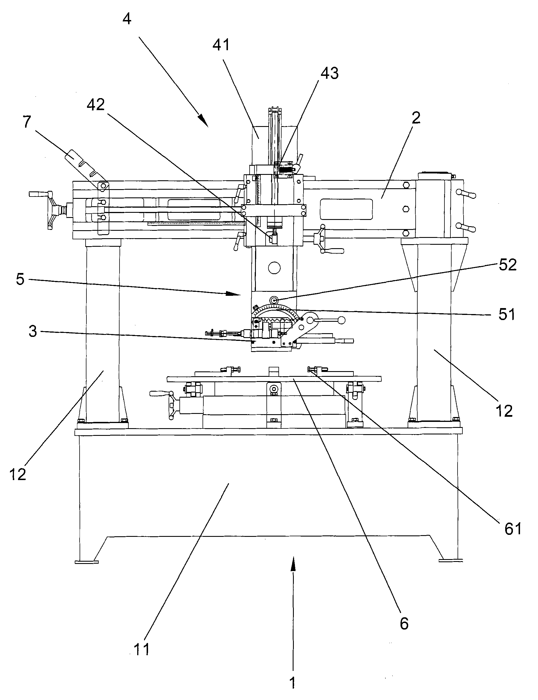
附图1为本发明的钻孔机的主视图;Accompanying
附图2为本发明的钻孔机的俯视图(横梁旋转到一旁);Accompanying
附图3为本发明的升降驱动机构的主视图;Accompanying
附图4为本发明的升降驱动机构的局部剖视图;Accompanying drawing 4 is the partial sectional view of lifting drive mechanism of the present invention;
附图5为本发明的升降机构的俯视图;Accompanying
附图6为本发明的倾斜调节装置的主视图;Accompanying
其中:1、机架;11、底座;12、立柱;2、横梁;3、加工头;31、钻头;32、进给齿条;33、进给齿轮;34、弹簧;35、钻头座;4、升降驱动机构;41、支架;411、导轨;42、粗调机构;43、微调机构;421、齿条;422、驱动齿轮;431、丝杆;432、开合螺母;433、弹性推杆;434、偏心轮;5、倾斜调节装置;51、扇齿轮;52、调节齿轮;6、工作台;61、卡爪;7、锁块。Among them: 1. Rack; 11. Base; 12. Column; 2. Beam; 3. Processing head; 31. Drill; 32. Feed rack; 33. Feed gear; 34. Spring; 35. Drill seat; 4. Lifting drive mechanism; 41. Bracket; 411. Guide rail; 42. Coarse adjustment mechanism; 43. Fine adjustment mechanism; 421. Rack; 422. Driving gear; 431. Screw rod; Rod; 434, eccentric wheel; 5, tilt adjustment device; 51, sector gear; 52, adjustment gear; 6, workbench; 61, claw; 7, lock block.
具体实施方式 Detailed ways
如图1所示的一种轮胎模具钻孔机,它设有一个机架1、该机架1包括一个底座11和固定地安装在底座11上的两根立柱12,两根立柱12的顶端设置有横梁12,横梁2的一端部通过一转轴可转动的设置在其中的一根立柱12的顶端部上,该转轴的轴心线沿铅垂线方向延伸,横梁2的另一端部通过锁块7锁定在另一根立柱12上,当需要转动横梁2时,只要挪开锁块7,在沿着这个转轴转动即可,如图2所示转动后的示意图,此图中刀头3没有随着转动,在实际操作过程中,在转动横梁2的时候,连接在其上的部件(如刀头3、升降驱动机构4)均随着转动,这样在加工完一个轮胎模具时,转动横梁3,使位于下侧的轮胎模具能够很方便的从工作台6上取下。A kind of tire mold drilling machine as shown in Figure 1, it is provided with a
机架1上连接有加工头3、在加工头3的下方设置有工作台6,工作台6可旋转的设置在底座11的上表面上,这样在加工轮胎模具时,只要旋转工作台6,工作人员不用移动就可以很方便的对整个轮胎模具进行加工,工作台6上还设置有用于将轮胎模具夹紧在工作台6上的卡爪61,通常卡爪61可延伸工作台6的径向伸缩以能够夹持不同直径的轮胎模具。加工头3上还设置有驱带动加工头3作升降运动的升降驱动机构4,为了使得加工更加方便、进一步提高加工精度,升降驱动机构4上同时设置了可分别调节加工头3作升降运动的粗调机构42和微调机构43,升降驱动机构4还设有一支架41,该支架41固定在横梁2上。The
粗调机构42由固定设置在支架41上且沿铅垂方向延伸的齿条421和可转动地设置加工头3上且与齿条421相啮合的驱动齿轮422组成。当旋转驱动齿轮422时,加工头3就能上升或下降以满足加工轮胎的高度要求。微调机构43由可转动地设置在支架41上的丝杆431和与丝杆431相配合的开合螺母432组成,开合螺母432上设置有弹性推杆433,弹性推杆433在远离开合螺母432的一端部设置有偏心轮434,偏心轮434与弹性推杆433的一端部相抵,弹性推杆433可推动开合螺母432抵紧在丝杆431上,从而使得丝杆431在转动时能够带动开合螺母432升降。The
为了使得加工头3能够左右倾斜,在其上还设置有倾斜调节装置5,倾斜调节装置5由固定在所述的加工头3上的扇齿轮51与可转动地设置在支架41上且与扇齿轮51相啮合的调节齿轮52构成,这样旋转调节齿轮52,这样扇齿轮51就会带动加工头3左右倾斜,从而满足加工需要。In order to enable the
加工头3包括钻头31、钻头座35,其中钻头31设置在钻头座35上,并且一般有一个马达带动其转动。支架41上设置有水平延伸的导轨411。钻头座35可沿导轨411滑动地设置在支架41上。钻头座35上固定有沿水平方向延伸的进给齿条32,进给齿条32上啮合有可转动的进给齿轮33,当旋转进给齿轮33时,进给齿轮33推动进给齿条32向前移动,从而使得钻头座35沿着导轨411水平滑动,从而达到钻头3 1的进给要求。为了使得钻头在进给加工完一个孔后能够恢复到原来的位置,在钻头座35和进给齿轮33之间设置有弹簧34。The
以上所述的仅为本发明的较佳实施例,凡是未脱离本发明技术方案内容的实施例均为本发明保护的范围。The above are only preferred embodiments of the present invention, and all embodiments that do not deviate from the content of the technical solution of the present invention are within the protection scope of the present invention.
Claims (7)
Priority Applications (1)
| Application Number | Priority Date | Filing Date | Title |
|---|---|---|---|
| CNB200710103659XA CN100496831C (en) | 2007-02-12 | 2007-04-29 | Tyre mold hole boring machine |
Applications Claiming Priority (3)
| Application Number | Priority Date | Filing Date | Title |
|---|---|---|---|
| CN200720034534.1 | 2007-02-12 | ||
| CN200720034534 | 2007-02-12 | ||
| CNB200710103659XA CN100496831C (en) | 2007-02-12 | 2007-04-29 | Tyre mold hole boring machine |
Publications (2)
| Publication Number | Publication Date |
|---|---|
| CN101066566A true CN101066566A (en) | 2007-11-07 |
| CN100496831C CN100496831C (en) | 2009-06-10 |
Family
ID=38879336
Family Applications (1)
| Application Number | Title | Priority Date | Filing Date |
|---|---|---|---|
| CNB200710103659XA Expired - Fee Related CN100496831C (en) | 2007-02-12 | 2007-04-29 | Tyre mold hole boring machine |
Country Status (1)
| Country | Link |
|---|---|
| CN (1) | CN100496831C (en) |
Cited By (29)
| Publication number | Priority date | Publication date | Assignee | Title |
|---|---|---|---|---|
| CN102029415A (en) * | 2011-02-15 | 2011-04-27 | 潘旭 | Automatic inner hole chamfering machine |
| CN103706832A (en) * | 2013-12-09 | 2014-04-09 | 淮南矿业(集团)有限责任公司 | Novel automatic drilling device |
| CN104227061A (en) * | 2013-06-21 | 2014-12-24 | 南通永明光纤材料有限公司 | Machining method for leading-in openings of inner holes of capillary tubes |
| CN105397148A (en) * | 2015-12-21 | 2016-03-16 | 山东云峰数控科技有限公司 | Special numerical control automatic drilling machine for tire mold |
| CN105414599A (en) * | 2015-12-16 | 2016-03-23 | 嵊州市西格玛科技有限公司 | Drilling device applied to graphite mold production |
| CN105478840A (en) * | 2016-01-05 | 2016-04-13 | 苏州市永通不锈钢有限公司 | Metal tube drilling machine |
| CN105478842A (en) * | 2016-01-05 | 2016-04-13 | 苏州市永通不锈钢有限公司 | Metal tube drilling machine capable of adjusting space |
| CN106112047A (en) * | 2016-08-04 | 2016-11-16 | 无锡尊宝电动车有限公司 | A kind of packaged type puncher for mining machinery boring |
| CN107030310A (en) * | 2017-04-28 | 2017-08-11 | 张世强 | A kind of shaft coupling processing drilling equipment for being easy to adjust |
| CN107175351A (en) * | 2017-05-22 | 2017-09-19 | 广东东箭汽车用品制造有限公司 | A kind of drilling equipment |
| CN108672740A (en) * | 2018-07-17 | 2018-10-19 | 太仓葛龙模具有限公司 | A kind of automobile die production and processing drilling equipment |
| CN109047862A (en) * | 2018-08-26 | 2018-12-21 | 陈秉辉 | A kind of electronic product production drilling part equipment |
| CN110341360A (en) * | 2019-08-27 | 2019-10-18 | 徐州腾睿智能装备有限公司 | A kind of dedusting function engraving machine and method |
| CN110405858A (en) * | 2019-08-27 | 2019-11-05 | 徐州绿源智能科技有限公司 | A kind of wood-worker engraving machine earnings pattern calculates and equipment |
| CN110481227A (en) * | 2019-08-27 | 2019-11-22 | 徐州绿源智能科技有限公司 | Benefit analysis and equipment of a CNC engraving machine |
| CN110481228A (en) * | 2019-08-27 | 2019-11-22 | 徐州绿源智能科技有限公司 | Production capacity evaluation and equipment of a high-precision three-dimensional engraving machine |
| CN110481222A (en) * | 2019-08-27 | 2019-11-22 | 徐州腾睿智能装备有限公司 | A kind of interchangeable engraving equipment of cutter head and method |
| CN110481223A (en) * | 2019-08-27 | 2019-11-22 | 徐州腾睿智能装备有限公司 | A kind of planar engraving machine cooler and method |
| CN110480059A (en) * | 2019-08-27 | 2019-11-22 | 徐州腾睿智能装备有限公司 | A kind of engraving equipment and method with translation structure |
| CN110481229A (en) * | 2019-08-27 | 2019-11-22 | 徐州绿源智能科技有限公司 | A kind of carving machine with multiple working positions benefit influence factor calculates and equipment |
| CN110496980A (en) * | 2019-08-27 | 2019-11-26 | 徐州腾睿智能装备有限公司 | One kind is based on the high-precision three-dimensional automatic engraving equipment of DSP and method |
| CN110497479A (en) * | 2019-08-27 | 2019-11-26 | 徐州绿源智能科技有限公司 | A kind of wood carving sawdust collects machine production prediction and equipment |
| CN110497726A (en) * | 2019-08-27 | 2019-11-26 | 徐州绿源智能科技有限公司 | A kind of electronic engraving machine benefit calculation and equipment |
| CN110508842A (en) * | 2019-08-27 | 2019-11-29 | 徐州腾睿智能装备有限公司 | A kind of light-duty stereo carving device and method |
| CN110509358A (en) * | 2019-08-27 | 2019-11-29 | 徐州绿源智能科技有限公司 | A kind of vertical engraving machine income parsing of environmental protection and equipment |
| CN110696155A (en) * | 2019-10-12 | 2020-01-17 | 徐州工程学院 | Mixed mud sample mummification section equipment |
| CN113290450A (en) * | 2021-06-24 | 2021-08-24 | 安庆机床有限公司 | Adjusting structure for steel ball processing equipment |
| CN115890271A (en) * | 2022-09-21 | 2023-04-04 | 江苏苏美达铝业有限公司 | Automobile wheel hub processing perforating machine easy to position |
| CN116652235A (en) * | 2023-06-12 | 2023-08-29 | 山东云峰数控科技有限公司 | Special automatic drilling machine for tire mold |
-
2007
- 2007-04-29 CN CNB200710103659XA patent/CN100496831C/en not_active Expired - Fee Related
Cited By (34)
| Publication number | Priority date | Publication date | Assignee | Title |
|---|---|---|---|---|
| CN102029415A (en) * | 2011-02-15 | 2011-04-27 | 潘旭 | Automatic inner hole chamfering machine |
| CN104227061A (en) * | 2013-06-21 | 2014-12-24 | 南通永明光纤材料有限公司 | Machining method for leading-in openings of inner holes of capillary tubes |
| CN103706832A (en) * | 2013-12-09 | 2014-04-09 | 淮南矿业(集团)有限责任公司 | Novel automatic drilling device |
| CN105414599A (en) * | 2015-12-16 | 2016-03-23 | 嵊州市西格玛科技有限公司 | Drilling device applied to graphite mold production |
| CN105397148A (en) * | 2015-12-21 | 2016-03-16 | 山东云峰数控科技有限公司 | Special numerical control automatic drilling machine for tire mold |
| CN105478842A (en) * | 2016-01-05 | 2016-04-13 | 苏州市永通不锈钢有限公司 | Metal tube drilling machine capable of adjusting space |
| CN105478840A (en) * | 2016-01-05 | 2016-04-13 | 苏州市永通不锈钢有限公司 | Metal tube drilling machine |
| CN106112047A (en) * | 2016-08-04 | 2016-11-16 | 无锡尊宝电动车有限公司 | A kind of packaged type puncher for mining machinery boring |
| CN107030310A (en) * | 2017-04-28 | 2017-08-11 | 张世强 | A kind of shaft coupling processing drilling equipment for being easy to adjust |
| CN107175351A (en) * | 2017-05-22 | 2017-09-19 | 广东东箭汽车用品制造有限公司 | A kind of drilling equipment |
| CN108672740A (en) * | 2018-07-17 | 2018-10-19 | 太仓葛龙模具有限公司 | A kind of automobile die production and processing drilling equipment |
| CN109047862A (en) * | 2018-08-26 | 2018-12-21 | 陈秉辉 | A kind of electronic product production drilling part equipment |
| CN109047862B (en) * | 2018-08-26 | 2020-03-06 | 深圳市奇力模具有限公司 | Part drilling equipment for producing electromechanical products |
| CN110481222A (en) * | 2019-08-27 | 2019-11-22 | 徐州腾睿智能装备有限公司 | A kind of interchangeable engraving equipment of cutter head and method |
| CN110509358A (en) * | 2019-08-27 | 2019-11-29 | 徐州绿源智能科技有限公司 | A kind of vertical engraving machine income parsing of environmental protection and equipment |
| CN110481228A (en) * | 2019-08-27 | 2019-11-22 | 徐州绿源智能科技有限公司 | Production capacity evaluation and equipment of a high-precision three-dimensional engraving machine |
| CN110405858A (en) * | 2019-08-27 | 2019-11-05 | 徐州绿源智能科技有限公司 | A kind of wood-worker engraving machine earnings pattern calculates and equipment |
| CN110481223A (en) * | 2019-08-27 | 2019-11-22 | 徐州腾睿智能装备有限公司 | A kind of planar engraving machine cooler and method |
| CN110480059A (en) * | 2019-08-27 | 2019-11-22 | 徐州腾睿智能装备有限公司 | A kind of engraving equipment and method with translation structure |
| CN110481229A (en) * | 2019-08-27 | 2019-11-22 | 徐州绿源智能科技有限公司 | A kind of carving machine with multiple working positions benefit influence factor calculates and equipment |
| CN110496980A (en) * | 2019-08-27 | 2019-11-26 | 徐州腾睿智能装备有限公司 | One kind is based on the high-precision three-dimensional automatic engraving equipment of DSP and method |
| CN110497479A (en) * | 2019-08-27 | 2019-11-26 | 徐州绿源智能科技有限公司 | A kind of wood carving sawdust collects machine production prediction and equipment |
| CN110497726A (en) * | 2019-08-27 | 2019-11-26 | 徐州绿源智能科技有限公司 | A kind of electronic engraving machine benefit calculation and equipment |
| CN110508842A (en) * | 2019-08-27 | 2019-11-29 | 徐州腾睿智能装备有限公司 | A kind of light-duty stereo carving device and method |
| CN110481227A (en) * | 2019-08-27 | 2019-11-22 | 徐州绿源智能科技有限公司 | Benefit analysis and equipment of a CNC engraving machine |
| CN110481227B (en) * | 2019-08-27 | 2021-04-09 | 徐州绿源智能科技有限公司 | Numerical control engraving equipment and benefit analysis method thereof |
| CN110341360A (en) * | 2019-08-27 | 2019-10-18 | 徐州腾睿智能装备有限公司 | A kind of dedusting function engraving machine and method |
| CN110481228B (en) * | 2019-08-27 | 2021-04-06 | 徐州绿源智能科技有限公司 | A kind of high-precision three-dimensional engraving equipment and its productivity evaluation method |
| CN110696155A (en) * | 2019-10-12 | 2020-01-17 | 徐州工程学院 | Mixed mud sample mummification section equipment |
| CN110696155B (en) * | 2019-10-12 | 2021-04-13 | 徐州工程学院 | Mixed mud sample mummification section equipment |
| CN113290450A (en) * | 2021-06-24 | 2021-08-24 | 安庆机床有限公司 | Adjusting structure for steel ball processing equipment |
| CN113290450B (en) * | 2021-06-24 | 2023-12-08 | 安庆机床有限公司 | Adjusting structure for steel ball processing equipment |
| CN115890271A (en) * | 2022-09-21 | 2023-04-04 | 江苏苏美达铝业有限公司 | Automobile wheel hub processing perforating machine easy to position |
| CN116652235A (en) * | 2023-06-12 | 2023-08-29 | 山东云峰数控科技有限公司 | Special automatic drilling machine for tire mold |
Also Published As
| Publication number | Publication date |
|---|---|
| CN100496831C (en) | 2009-06-10 |
Similar Documents
| Publication | Publication Date | Title |
|---|---|---|
| CN100496831C (en) | Tyre mold hole boring machine | |
| CN101774310B (en) | Cylindrical workpiece code word machine | |
| CN1647879A (en) | Boring processing machine for ship rudder | |
| CN108000643A (en) | A kind of Multifunctional carpenter drilling machine | |
| CN201079876Y (en) | Vertical tapping machine | |
| CN2526114Y (en) | Milling machine for internal hole key seat of large parts | |
| CN215966650U (en) | Aluminum pipe fixed length saw cuts machine | |
| CN113334086B (en) | Automobile chassis bearing square tube machining mechanism | |
| CN214134154U (en) | Workpiece milling equipment | |
| CN201613705U (en) | Rapid cylindrical workpiece code word machine | |
| CN220591625U (en) | Be used for irregular aluminium alloy surface drilling equipment | |
| CN113333807A (en) | Angle type drilling machine capable of continuously turning at right angle and using method thereof | |
| CN220330522U (en) | Six-head air suction locking screw equipment | |
| CN2611081Y (en) | Automatic machine for horizontally drilling stone | |
| CN101293293B (en) | Spark machine tool special for tyre mould process | |
| CN209792700U (en) | Milling machine convenient for displacement control | |
| CN221415169U (en) | Straight pipe intersecting line cutting positioning assembly | |
| CN2631672Y (en) | Multipurpose Horizontal Deep Hole Drilling Machine | |
| CN111037660A (en) | Cutting device is used in production of fitment plank | |
| CN216828818U (en) | Automatic milling flutes mechanism of sensor | |
| CN213916321U (en) | Double-sided milling device | |
| CN212743471U (en) | Dig wall telephone | |
| CN108568670B (en) | Vertical machining center deep hole drilling and milling bracket | |
| CN221516143U (en) | Drilling machine convenient to adjust | |
| CN205309377U (en) | Radial tire mould curb plate puncher |
Legal Events
| Date | Code | Title | Description |
|---|---|---|---|
| C06 | Publication | ||
| PB01 | Publication | ||
| C10 | Entry into substantive examination | ||
| SE01 | Entry into force of request for substantive examination | ||
| C14 | Grant of patent or utility model | ||
| GR01 | Patent grant | ||
| ASS | Succession or assignment of patent right |
Owner name: SUZHOU INDUSTRIAL PARK Free format text: FORMER OWNER: ZHUANG TIANCAI Effective date: 20120711 |
|
| C41 | Transfer of patent application or patent right or utility model | ||
| COR | Change of bibliographic data |
Free format text: CORRECT: ADDRESS; FROM: 215331 SUZHOU, JIANGSU PROVINCE TO: 215122 SUZHOU, JIANGSU PROVINCE |
|
| TR01 | Transfer of patent right |
Effective date of registration: 20120711 Address after: 215122 Suzhou Industrial Park Kuatang Industrial Zone Ruihua Road No. 18 Patentee after: Suzhou Industrial Park Jinxin Mold Manufacturing Co.,Ltd. Address before: 215331 Jiangsu city of Kunshan province Lujia Xudong machinery (Kunshan) Co., Ltd. in Patentee before: Zhuang Tiancai |
|
| CF01 | Termination of patent right due to non-payment of annual fee |
Granted publication date: 20090610 Termination date: 20160429 |
|
| CF01 | Termination of patent right due to non-payment of annual fee |