CN101035953B - Sanitary vanity accessories - Google Patents
Sanitary vanity accessories Download PDFInfo
- Publication number
- CN101035953B CN101035953B CN2005800341999A CN200580034199A CN101035953B CN 101035953 B CN101035953 B CN 101035953B CN 2005800341999 A CN2005800341999 A CN 2005800341999A CN 200580034199 A CN200580034199 A CN 200580034199A CN 101035953 B CN101035953 B CN 101035953B
- Authority
- CN
- China
- Prior art keywords
- washstand
- housing
- base
- turn
- spring ring
- Prior art date
- Legal status (The legal status is an assumption and is not a legal conclusion. Google has not performed a legal analysis and makes no representation as to the accuracy of the status listed.)
- Expired - Fee Related
Links
Images


Classifications
-
- E—FIXED CONSTRUCTIONS
- E03—WATER SUPPLY; SEWERAGE
- E03C—DOMESTIC PLUMBING INSTALLATIONS FOR FRESH WATER OR WASTE WATER; SINKS
- E03C1/00—Domestic plumbing installations for fresh water or waste water; Sinks
- E03C1/02—Plumbing installations for fresh water
- E03C1/04—Water-basin installations specially adapted to wash-basins or baths
- E03C1/0401—Fixing a tap to the sanitary appliance or to an associated mounting surface, e.g. a countertop
-
- E—FIXED CONSTRUCTIONS
- E03—WATER SUPPLY; SEWERAGE
- E03C—DOMESTIC PLUMBING INSTALLATIONS FOR FRESH WATER OR WASTE WATER; SINKS
- E03C1/00—Domestic plumbing installations for fresh water or waste water; Sinks
- E03C1/02—Plumbing installations for fresh water
- E03C1/04—Water-basin installations specially adapted to wash-basins or baths
- E03C2001/0416—Water-basin installations specially adapted to wash-basins or baths using a socket for mounting of faucet
Landscapes
- Health & Medical Sciences (AREA)
- Life Sciences & Earth Sciences (AREA)
- Engineering & Computer Science (AREA)
- Hydrology & Water Resources (AREA)
- Public Health (AREA)
- Water Supply & Treatment (AREA)
- Domestic Plumbing Installations (AREA)
- Sink And Installation For Waste Water (AREA)
- Orthopedics, Nursing, And Contraception (AREA)
- Absorbent Articles And Supports Therefor (AREA)
Abstract
Description
技术领域technical field
本发明涉及一种卫生盥洗台配件,它具有壳体,该壳体借助于固定装置可拆卸地固定在盥洗台上。The invention relates to a sanitary washstand fitting which has a housing which is releasably fastened to the washstand by means of fastening means.
背景技术Background technique
公知的卫生盥洗台配件的固定元件可从上方插入到盥洗台的孔中并且从下方通过旋紧而固定。通常,盥洗台难以从下方接近,从而装配者经常必须采取不舒适且不利健康的姿态。此外,从下方通过旋拧而连接盥洗台配件费事且耗时。The fixing elements of the known sanitary washstand fittings can be inserted from above into holes in the washstand and fixed from below by screwing on. Often, washstands are difficult to access from below, so that the fitter often has to assume uncomfortable and unhealthy postures. Furthermore, connecting the washstand fittings from below by screwing is complex and time-consuming.
发明内容Contents of the invention
本发明的目的在于,这样设计一种开头所述类型的卫生盥洗台配件,使得该卫生盥洗台配件无需大的技术投入就可基本上从上方稳定地安装在盥洗台上。The object of the present invention is to devise a sanitary washstand fitting of the type mentioned at the outset in such a way that it can be mounted substantially stably on the washstand from above without major technical effort.
根据本发明,该目的这样来实现,即卫生盥洗台配件具有壳体,该壳体借助于固定装置可拆卸地固定在盥洗台上,所述固定装置包括:According to the invention, this object is achieved in that the sanitary washstand fitting has a housing which is fastened detachably to the washstand by means of fastening means comprising:
a)能够固定在盥洗台上的基座;a) a base that can be fixed on the washstand;
b)插接装置,通过该插接装置能够使壳体从上方套在基座上;b) a plug-in device, by means of which the housing can be placed on the base from above;
c)卡紧装置,通过该卡紧装置能够使被套上的壳体相对基座锁定;c) a clamping device, through which the shell to be covered can be locked relative to the base;
其中,所述基座具有弹簧圈槽,该弹簧圈槽带有弹簧圈,该弹簧圈具有切口,所述壳体在与所述弹簧圈槽相同的高度上具有与所述弹簧圈槽互补的配合槽,所述弹簧圈通过能够旋入到所述壳体中的螺纹通孔中以使所述弹簧圈在所述切口处的端面彼此分开的螺纹销径向可扩张。Wherein, the base has a spring coil groove with a spring coil, the spring coil has a cutout, and the housing has a complementary hole to the spring coil groove at the same height as the spring coil groove. Cooperating with the groove, the spring ring is radially expandable by a threaded pin screwed into a threaded through hole in the housing to separate the end faces of the spring ring at the cutouts from each other.
因此,根据本发明,该卫生盥洗台配件可从上方安装到盥洗台上。为此,壳体从上方套上并且通过卡紧装置固定在预装好的基座上,这可快速且无需技术投入地进行。只是与角阀的连接和拉杆在排出附件上的装配在盥洗台下方进行。基座因此形成用于盥洗台配件的多个互补壳体的适配器,这些盥洗台配件可快速且简单地彼此调换。Thus, according to the invention, the sanitary washstand fitting can be mounted on the washstand from above. For this purpose, the housing is slipped on from above and fastened to the preassembled base by clamping devices, which can be done quickly and without technical effort. Only the connection to the angle valve and the assembly of the tie rod to the outlet attachment take place under the washstand. The base thus forms an adapter for a plurality of complementary housings of washstand fittings, which can be exchanged quickly and easily for one another.
特别有利的是,所述弹簧圈能够通过所述螺纹销尤其是在盥洗台上方被张紧或解除张力,从而显著降低了工作投入。It is particularly advantageous that the spring coil can be tensioned and detensioned by means of the threaded pin, especially above the washstand, so that the work effort is considerably reduced.
为了保证弹簧圈的切口始终定位在螺纹销的区域中,以有利的方式在所述槽中设置用于弹簧圈的定位销。In order to ensure that the cutout of the spring coil is always positioned in the region of the threaded pin, a positioning pin for the spring coil is advantageously provided in the groove.
在另一个有利的实施形式中显著简化了导水管道的装配,在该实施形式中,所述基座具有至少一个用于导水管道的连接元件。In another advantageous embodiment, the assembly of the water-conducting line is considerably simplified, in which the base has at least one connecting element for the water-conducting line.
附图说明Description of drawings
下面借助于附图详细说明本发明的实施例,附图中:Embodiments of the present invention are described in detail below by means of the accompanying drawings, in the accompanying drawings:
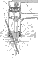
图1示意性示出安装在盥洗台上的盥洗台配件的轴向剖面;Figure 1 schematically shows an axial section of a washstand fitting mounted on a washstand;
图2示意性示出图1中所示盥洗台配件沿图1中的线II-II的剖面;Figure 2 schematically shows a section of the washstand fitting shown in Figure 1 along the line II-II in Figure 1;
图3示意性示出图1中所示盥洗台配件在这里以未张紧形式示出的卡紧装置的区域中沿图4中的线III-III的放大水平剖面;FIG. 3 schematically shows an enlarged horizontal section along the line III-III in FIG. 4 in the region of the clamping device shown here in untensioned form for the washstand fitting shown in FIG. 1;
图4示出图1中的局部放大视图;Figure 4 shows a partially enlarged view in Figure 1;
图5示出图4中所示卡紧装置在调节元件的区域中的进一步放大的细节视图;FIG. 5 shows a further enlarged detail view of the clamping device shown in FIG. 4 in the region of the adjustment element;
图6示出沿图5中的线VI-VI剖切图5的水平剖面;Figure 6 shows a horizontal section of Figure 5 along the line VI-VI in Figure 5;
图7示意性示出图1中所示盥洗台配件的放大水平剖面,其与图3类似但所示的卡紧装置被张紧;Figure 7 schematically shows an enlarged horizontal section of the vanity fitting shown in Figure 1, similar to Figure 3 but with the clamping means shown tensioned;
图8示意性示出与图4类似的视图,卡紧装置被张紧;Figure 8 schematically shows a view similar to Figure 4, with the clamping device being tensioned;
图9示出图8中在弹簧圈的区域中的进一步放大的细节视图;FIG. 9 shows a further enlarged detail view of FIG. 8 in the region of the coils;
图10示出图8中在调节元件的区域中的细节视图。FIG. 10 shows a detail view of FIG. 8 in the region of the adjustment element.
具体实施方式Detailed ways
图1中示出了盥洗台配件1,该盥洗台配件从上方固定在盥洗台2上。FIG. 1 shows a washstand fitting 1 which is fastened to a
盥洗台配件1包括一壳体3,在图1中右上方从该壳体伸出一水流出部4。在壳体3中在上部设置有可通过混合器杠杆6操作的本身公知的混水腔(Kartusche)5。The washstand fitting 1 comprises a
在壳体3内部,两个上部的水注入管道7从下方通到混水腔5。Inside the
壳体3在其下部区域中基本上具有圆形空心柱的形状,该下部区域同时构成固定装置8。该壳体套在基座9上,该基座也为圆柱状且其外截面与壳体3的下部区域的内截面互补。沿着基座9的外壳面的上部区域,O型密封圈10设置在槽11中以便密封。The
基座9通过具有外螺纹的基座螺栓12固定在盥洗台2的上侧上。在基座9与盥洗台2之间设置有普通垫圈13。The
基座螺栓12在图1中左侧垂直地从基座9的下端面伸出。该基座螺栓插过盥洗台2中用于该螺栓的通孔,并且从下方通过卡紧垫圈14和未示出的螺母固定。A
此外,在图2中的正视图中,在基座9中设置有两个本身公知的连接元件15,该连接元件用于使上部的水注入管道7与两个从下方穿过盥洗台2中的相应孔16的下部的水注入管道17相连接。Furthermore, in the front view in FIG. 2 , two
基座9还具有用于拉杆19的通孔18,该拉杆用于未示出的排出附件。The
为了将壳体3固定在基座9上,设置有作为固定装置8的附加部分的卡紧装置20。所述卡紧装置包括弹簧圈21,该弹簧圈设置在一个在基座9的外壳中环绕的弹簧圈槽22中。For fastening the
弹簧圈21在未张紧状态下几乎完全沉没在弹簧圈槽22中并且不伸出超过或仅很少地超过基座9的外壳(图3至图6)。在壳体3的内壳面中,在弹簧圈槽22的高度上设置有一个具有V形截面的配合槽23,弹簧圈21在张紧状态下部分地被推入到该配合槽中(图7至图10)。In the untensioned state, the
弹簧圈21在图3中其右侧上被开切口。弹簧圈21的切口24在图6中详细示出。弹簧圈21的相对端面在图6中其左侧的四分之一部分中具有两个彼此平行的平面25。在该平面25的右侧,所述端面各以45°倾斜,从而切口24总体上具有90°缺口部26。The
当弹簧圈21处于未张紧状态时,平面25靠置在定位销27上。定位销27设置在弹簧圈槽22的在图5中为下壁的壁上,并且防止弹簧圈21在弹簧圈槽22中扭转。When the
在图6的详细视图中相对于弹簧圈21的切口24向右延伸的延长线上,壳体3的外壳具有螺纹通孔28,螺纹销29作为用于弹簧圈21的调节元件旋入到该螺纹通孔中。螺纹销29的朝向弹簧圈21的左侧边缘以45°被斜切,由此实现具有90°锥顶角的截锥部30,该截锥部与弹簧圈21的切口24的90°缺口部26互补。In the extension of the
如果螺纹销29沿顺时针方向转动,则截锥部30向左被推入到90°缺口部26中,从而使得弹簧圈21的端面在图7中分别向上和向下彼此分开,这在图10中以剖面视图详细示出。由此,弹簧圈21总地径向扩张,并且从弹簧圈槽22中出来压入到壳体3的配合槽23中,这在图8和图9中以剖面视图示出。If the threaded
在完全张紧的状态下,弹簧圈21在图9的详细视图中以其左侧的外部三分之一部分嵌入到配合槽23中,并且其朝向基座9的、图9中右侧的内部区域保留在弹簧圈槽22中,由此使基座9相对于壳体3卡紧。In the fully tensioned state, the
为了安装盥洗台配件1,首先通过基座螺栓12将基座9固定到盥洗台2上并且使连接元件16从图1中下方与下部的水注入管道17相连接。接着,使螺纹销29沿逆时针方向从壳体3的外壳中的螺纹孔中转动出来,直到该螺纹销不再伸出超过该壳体的内壳面。此外,使壳体3从图1中上方套到基座9上,同时使上部的水注入管道7与连接元件16相连接。此后,使螺纹销29沿顺时针方向转动,直到弹簧圈21完全张紧并且壳体3固定地卡紧在基座9上。最后,使拉杆19插过相应孔并且以本身公知的方式与排出附件相连接。To install the washstand fitting 1 , the
基座9也可用与通过基座螺栓12、卡紧垫圈14和螺母不同的方式固定在盥洗台2上。The
卡紧装置20例如也可通过壳体3中的多个埋头螺钉来实现,这些埋头螺钉旋入到基座9的外壳中的槽中。The clamping
取代圆形的截面,弹簧圈21也可具有有角的或椭圆的截面。Instead of a circular cross section, the
取代具有截锥部30的螺纹销29,也可使用具有非圆形、尤其是椭圆形截面的销,借助于这种销通过转动将弹簧圈21的开口24的在此情况下优选平行的端面彼此压开。Instead of threaded
Claims (4)
Applications Claiming Priority (3)
| Application Number | Priority Date | Filing Date | Title |
|---|---|---|---|
| DE102004049736.2 | 2004-10-13 | ||
| DE102004049736A DE102004049736B4 (en) | 2004-10-13 | 2004-10-13 | Sanitary washbasin faucet |
| PCT/EP2005/010859 WO2006040102A1 (en) | 2004-10-13 | 2005-10-08 | Attachment of a sanitary washstand fitting to a washstand |
Publications (2)
| Publication Number | Publication Date |
|---|---|
| CN101035953A CN101035953A (en) | 2007-09-12 |
| CN101035953B true CN101035953B (en) | 2010-05-05 |
Family
ID=35478903
Family Applications (1)
| Application Number | Title | Priority Date | Filing Date |
|---|---|---|---|
| CN2005800341999A Expired - Fee Related CN101035953B (en) | 2004-10-13 | 2005-10-08 | Sanitary vanity accessories |
Country Status (7)
| Country | Link |
|---|---|
| US (1) | US8112832B2 (en) |
| EP (1) | EP1799920B1 (en) |
| JP (1) | JP2008516118A (en) |
| CN (1) | CN101035953B (en) |
| AT (1) | ATE410558T1 (en) |
| DE (2) | DE102004049736B4 (en) |
| WO (1) | WO2006040102A1 (en) |
Families Citing this family (13)
| Publication number | Priority date | Publication date | Assignee | Title |
|---|---|---|---|---|
| FI121756B (en) | 2009-05-15 | 2011-03-31 | Grana Finland Ab Oy | Method and apparatus for attaching a crane to a base support |
| GB2476314B (en) * | 2009-12-21 | 2015-07-08 | John Patrick Manning | Tap |
| US8453669B2 (en) * | 2010-07-21 | 2013-06-04 | Masco Corporation Of Indiana | Waterway adapter |
| US9702129B2 (en) * | 2011-08-02 | 2017-07-11 | Max Homami | Adjustable overflow closure device |
| DE102013225964A1 (en) * | 2013-12-13 | 2015-06-18 | Hansgrohe Se | Device for fastening a valve stem |
| FR3044333B1 (en) * | 2015-11-27 | 2019-08-23 | Somatherm | ANCHORING ELEMENT FOR FIXING VALVES |
| GB2552369B (en) * | 2016-07-21 | 2021-09-08 | Kohler Mira Ltd | Plumbing fixtures |
| JP7152698B2 (en) * | 2018-06-22 | 2022-10-13 | Toto株式会社 | Faucet device and manufacturing method thereof |
| CN110594446B (en) * | 2018-06-12 | 2022-03-22 | Toto株式会社 | Faucet assembly and method of manufacturing the same |
| JP7222251B2 (en) * | 2019-01-22 | 2023-02-15 | Toto株式会社 | faucet device |
| DE102020124086A1 (en) | 2020-09-16 | 2022-03-17 | Deutsches Zentrum für Luft- und Raumfahrt e.V. | coupling device |
| ES1257124Y (en) * | 2020-09-25 | 2021-02-16 | Garcia Jesus Tamarit | UNIVERSAL QUICK CONNECTION KIT FOR MOUNTING A TAP ON A BATTERY WITH A THROUGH HOLE |
| GB2643575A (en) * | 2024-08-23 | 2026-02-25 | Kohler Mira Ltd | Nut arrangement for a plumbing fitting |
Citations (5)
| Publication number | Priority date | Publication date | Assignee | Title |
|---|---|---|---|---|
| US5681060A (en) * | 1994-01-29 | 1997-10-28 | Armaturenfabrik Hermann Voss Gmbh & Co. | Plug-in connector for a pressure pipe system |
| US6328059B1 (en) * | 2000-03-22 | 2001-12-11 | Alessandro Testori | Top mounted faucet assembly |
| EP1357233A1 (en) * | 1997-03-19 | 2003-10-29 | Inax Corporation | Structure for fixing faucet |
| CN1455057A (en) * | 2002-05-01 | 2003-11-12 | 宇吕电子工业株式会社 | Water tap |
| CN1521367A (en) * | 2003-01-28 | 2004-08-18 | System and technique for mounting a faucet |
Family Cites Families (5)
| Publication number | Priority date | Publication date | Assignee | Title |
|---|---|---|---|---|
| AT205425B (en) * | 1957-12-16 | 1959-09-25 | Gustav Schmiedl | Eccentric shift lever for sanitary fittings |
| MX9601490A (en) * | 1995-09-28 | 1997-03-29 | Emhart Inc | Hub connection assembly. |
| DE29516157U1 (en) * | 1995-10-12 | 1997-02-20 | Dr. Fischer Ag, Vaduz | Device for holding a sanitary fitting |
| JP3196687B2 (en) | 1997-05-23 | 2001-08-06 | 株式会社イナックス | Faucet mounting structure |
| CH694918A5 (en) | 2000-12-21 | 2005-09-15 | Kwc Ag | Fitting with two fitting parts. |
-
2004
- 2004-10-13 DE DE102004049736A patent/DE102004049736B4/en not_active Expired - Fee Related
-
2005
- 2005-10-08 WO PCT/EP2005/010859 patent/WO2006040102A1/en not_active Ceased
- 2005-10-08 DE DE502005005647T patent/DE502005005647D1/en not_active Expired - Lifetime
- 2005-10-08 AT AT05796207T patent/ATE410558T1/en active
- 2005-10-08 EP EP05796207A patent/EP1799920B1/en not_active Expired - Lifetime
- 2005-10-08 CN CN2005800341999A patent/CN101035953B/en not_active Expired - Fee Related
- 2005-10-08 US US11/665,389 patent/US8112832B2/en not_active Expired - Fee Related
- 2005-10-08 JP JP2007536059A patent/JP2008516118A/en active Pending
Patent Citations (5)
| Publication number | Priority date | Publication date | Assignee | Title |
|---|---|---|---|---|
| US5681060A (en) * | 1994-01-29 | 1997-10-28 | Armaturenfabrik Hermann Voss Gmbh & Co. | Plug-in connector for a pressure pipe system |
| EP1357233A1 (en) * | 1997-03-19 | 2003-10-29 | Inax Corporation | Structure for fixing faucet |
| US6328059B1 (en) * | 2000-03-22 | 2001-12-11 | Alessandro Testori | Top mounted faucet assembly |
| CN1455057A (en) * | 2002-05-01 | 2003-11-12 | 宇吕电子工业株式会社 | Water tap |
| CN1521367A (en) * | 2003-01-28 | 2004-08-18 | System and technique for mounting a faucet |
Also Published As
| Publication number | Publication date |
|---|---|
| WO2006040102A1 (en) | 2006-04-20 |
| US20070261167A1 (en) | 2007-11-15 |
| EP1799920B1 (en) | 2008-10-08 |
| DE502005005647D1 (en) | 2008-11-20 |
| EP1799920A1 (en) | 2007-06-27 |
| DE102004049736B4 (en) | 2009-09-17 |
| CN101035953A (en) | 2007-09-12 |
| ATE410558T1 (en) | 2008-10-15 |
| HK1106808A1 (en) | 2008-03-20 |
| DE102004049736A1 (en) | 2006-06-22 |
| US8112832B2 (en) | 2012-02-14 |
| JP2008516118A (en) | 2008-05-15 |
Similar Documents
| Publication | Publication Date | Title |
|---|---|---|
| US20050098221A1 (en) | Modular center set faucet and valve body | |
| US4848395A (en) | Mixing faucet | |
| TW554147B (en) | Water lock tap | |
| US3790966A (en) | Quick-change faucet | |
| US9032985B2 (en) | Tap mounting for a plumbing fixture | |
| CN101035953A (en) | Attachment of a sanitary washstand fitting to a washstand | |
| CN206607638U (en) | Fixing device | |
| CA2921149A1 (en) | Faucet with a quick fastening device | |
| US20160138253A1 (en) | Quick Assembly Structure of Faucet Handle Base | |
| KR20200059647A (en) | A receiving bracket having a one-touch binding member | |
| US10329746B2 (en) | Plumbing fitting having a hose connection fastened with a clamp | |
| JP6441758B2 (en) | Water supply to hot water mixer tap and hot water supply hose assembly mechanism | |
| JP3335565B2 (en) | Faucet mounting device | |
| KR20160003377U (en) | Faucet fixed structure | |
| HK1106808B (en) | Sanitary washstand fitting | |
| JP4898554B2 (en) | Mounting structure for branch water supply adapter to vertical water faucet | |
| CN101107402B (en) | Sanitary fitting comprising a connecting device which is used to connect a water outlet housing to a functional component | |
| KR200497649Y1 (en) | Assembly for fixing warm and cold water supply hose of faucet | |
| KR200390670Y1 (en) | An Integrated Adaptor for Pipe | |
| US20040050422A1 (en) | Easy-to-install faucet handle assembly | |
| GB2592837A (en) | Tap fitting | |
| JP3931272B2 (en) | Faucet mounting structure | |
| JPH08233126A (en) | Water faucet mounting structure with shape memory material | |
| KR200312409Y1 (en) | Fix structure of washing machine waterworks | |
| GB2525256A (en) | A tap body attachment |
Legal Events
| Date | Code | Title | Description |
|---|---|---|---|
| C06 | Publication | ||
| PB01 | Publication | ||
| C10 | Entry into substantive examination | ||
| SE01 | Entry into force of request for substantive examination | ||
| REG | Reference to a national code |
Ref country code: HK Ref legal event code: DE Ref document number: 1106808 Country of ref document: HK |
|
| C14 | Grant of patent or utility model | ||
| GR01 | Patent grant | ||
| REG | Reference to a national code |
Ref country code: HK Ref legal event code: GR Ref document number: 1106808 Country of ref document: HK |
|
| CF01 | Termination of patent right due to non-payment of annual fee | ||
| CF01 | Termination of patent right due to non-payment of annual fee |
Granted publication date: 20100505 Termination date: 20201008 |