CN100523289C - Method and apparatus for the delivery of precursor materials - Google Patents
Method and apparatus for the delivery of precursor materials Download PDFInfo
- Publication number
- CN100523289C CN100523289C CNB2004100832841A CN200410083284A CN100523289C CN 100523289 C CN100523289 C CN 100523289C CN B2004100832841 A CNB2004100832841 A CN B2004100832841A CN 200410083284 A CN200410083284 A CN 200410083284A CN 100523289 C CN100523289 C CN 100523289C
- Authority
- CN
- China
- Prior art keywords
- container
- fluid
- precursor
- lid
- space
- Prior art date
- Legal status (The legal status is an assumption and is not a legal conclusion. Google has not performed a legal analysis and makes no representation as to the accuracy of the status listed.)
- Active
Links
Images


Classifications
-
- H—ELECTRICITY
- H01—ELECTRIC ELEMENTS
- H01L—SEMICONDUCTOR DEVICES NOT COVERED BY CLASS H10
- H01L21/00—Processes or apparatus adapted for the manufacture or treatment of semiconductor or solid state devices or of parts thereof
- H01L21/02—Manufacture or treatment of semiconductor devices or of parts thereof
- H01L21/04—Manufacture or treatment of semiconductor devices or of parts thereof the devices having at least one potential-jump barrier or surface barrier, e.g. PN junction, depletion layer or carrier concentration layer
- H01L21/18—Manufacture or treatment of semiconductor devices or of parts thereof the devices having at least one potential-jump barrier or surface barrier, e.g. PN junction, depletion layer or carrier concentration layer the devices having semiconductor bodies comprising elements of Group IV of the Periodic System or AIIIBV compounds with or without impurities, e.g. doping materials
- H01L21/20—Deposition of semiconductor materials on a substrate, e.g. epitaxial growth solid phase epitaxy
-
- C—CHEMISTRY; METALLURGY
- C23—COATING METALLIC MATERIAL; COATING MATERIAL WITH METALLIC MATERIAL; CHEMICAL SURFACE TREATMENT; DIFFUSION TREATMENT OF METALLIC MATERIAL; COATING BY VACUUM EVAPORATION, BY SPUTTERING, BY ION IMPLANTATION OR BY CHEMICAL VAPOUR DEPOSITION, IN GENERAL; INHIBITING CORROSION OF METALLIC MATERIAL OR INCRUSTATION IN GENERAL
- C23C—COATING METALLIC MATERIAL; COATING MATERIAL WITH METALLIC MATERIAL; SURFACE TREATMENT OF METALLIC MATERIAL BY DIFFUSION INTO THE SURFACE, BY CHEMICAL CONVERSION OR SUBSTITUTION; COATING BY VACUUM EVAPORATION, BY SPUTTERING, BY ION IMPLANTATION OR BY CHEMICAL VAPOUR DEPOSITION, IN GENERAL
- C23C16/00—Chemical coating by decomposition of gaseous compounds, without leaving reaction products of surface material in the coating, i.e. chemical vapour deposition [CVD] processes
- C23C16/44—Chemical coating by decomposition of gaseous compounds, without leaving reaction products of surface material in the coating, i.e. chemical vapour deposition [CVD] processes characterised by the method of coating
- C23C16/448—Chemical coating by decomposition of gaseous compounds, without leaving reaction products of surface material in the coating, i.e. chemical vapour deposition [CVD] processes characterised by the method of coating characterised by the method used for generating reactive gas streams, e.g. by evaporation or sublimation of precursor materials
- C23C16/4481—Chemical coating by decomposition of gaseous compounds, without leaving reaction products of surface material in the coating, i.e. chemical vapour deposition [CVD] processes characterised by the method of coating characterised by the method used for generating reactive gas streams, e.g. by evaporation or sublimation of precursor materials by evaporation using carrier gas in contact with the source material
-
- Y—GENERAL TAGGING OF NEW TECHNOLOGICAL DEVELOPMENTS; GENERAL TAGGING OF CROSS-SECTIONAL TECHNOLOGIES SPANNING OVER SEVERAL SECTIONS OF THE IPC; TECHNICAL SUBJECTS COVERED BY FORMER USPC CROSS-REFERENCE ART COLLECTIONS [XRACs] AND DIGESTS
- Y10—TECHNICAL SUBJECTS COVERED BY FORMER USPC
- Y10T—TECHNICAL SUBJECTS COVERED BY FORMER US CLASSIFICATION
- Y10T137/00—Fluid handling
- Y10T137/0318—Processes
- Y10T137/0391—Affecting flow by the addition of material or energy
-
- Y—GENERAL TAGGING OF NEW TECHNOLOGICAL DEVELOPMENTS; GENERAL TAGGING OF CROSS-SECTIONAL TECHNOLOGIES SPANNING OVER SEVERAL SECTIONS OF THE IPC; TECHNICAL SUBJECTS COVERED BY FORMER USPC CROSS-REFERENCE ART COLLECTIONS [XRACs] AND DIGESTS
- Y10—TECHNICAL SUBJECTS COVERED BY FORMER USPC
- Y10T—TECHNICAL SUBJECTS COVERED BY FORMER US CLASSIFICATION
- Y10T137/00—Fluid handling
- Y10T137/4891—With holder for solid, flaky or pulverized material to be dissolved or entrained
Abstract
Vessel and method for the production and delivery of a precursor-containing fluid stream comprising the gaseous phase of a precursor material are disclosed herein. In one aspect, there is provided an vessel comprising: an interior volume wherein the interior volume is segmented into an upper volume and a lower volume wherein the upper volume and the lower volume are in fluid communication; a lid comprising a fluid inlet, a fluid outlet, an optional fill port, and an internal recess wherein at least a portion of the upper volume resides within the internal recess; a sidewall interposed between the lid and a base; and at least one protrusion that extends into the lower volume wherein the precursor is in contact with the at least one protrusion and wherein at least one protrusion extends from at least one selected from the lid, the sidewall, the base, and combinations thereof.
Description
The cross-reference of related application
The application requires the No.60/496 of application on August 19th, 2003, the No.60/587 of 187 U.S. Provisional Applications and application on July 12nd, 2004, the rights and interests of 295 U.S. Provisional Applications.
Background technology
In one or more steps of producing semiconductor devices, sedimentation, for example chemical vapour deposition and atomic layer deposition method are often used at substrate surface and form one or more layers film or coating.In typical C VD method or ALD method, can be that the precursor source of solid phase and/or liquid phase is sent in one the reaction chamber that contains in a plurality of substrates, wherein precursor reacts under certain temperature or pressure condition, forms coating or film at substrate surface.
When a kind of solid precursor material is applied to CVD method or ALD method, usually this precursor material is heated in such as baking oven a separate chamber is enough to make it to form the temperature of gas, this gas is sent to reaction chamber then, and this gas and carrier gases are sent to reaction chamber together usually.In some cases, solid precursor material does not form the intermediary liquid phase but is heated directly to gas phase.The vaporization of solid precursor material when producing and the steam that will contain precursor a lot of problems can appear when being sent in the reaction chamber.The typical problem that runs into is including, but not limited to following situation: form deposition in container, vaporizer and/or transfer conduit; Liquid phase or solid phase material condense in container, vaporizer and/or transfer conduit, thereby form " cold spot " at internal tank; And inconsistent steam flows to the downstream reaction chamber.These problems may cause making in order to remove liquid or particulate matter " stop time " of production unit to prolong, and may produce the relatively poor relatively deposit film of quality.
Summary of the invention
The invention discloses a kind of container and method that is used for producing and transporting the fluid stream that comprises precursor, described fluid stream contains the gas phase of precursor material, if this container and method do not have all partly to have satisfied the needs of technology yet.Particularly, on the one hand, the invention provides a kind of container that is used for carrying the fluid stream that contains precursor that comes from precursor, this container comprises: an internal space, this internal space is divided into upper space and lower space, wherein fluid communication between upper space and the lower space; A lid, this lid comprise a fluid intake, a fluid outlet, an optional charging bole, and an internal recess, and wherein at least a portion of upper space is positioned at the inside of internal recess; Sidewall between lid and bottom; And at least one extends to the projection of lower space, and precursor contacts with described at least one projection and described at least one projection begins to extend from lid, sidewall, bottom and combination thereof in lower space.
The invention provides the container that another is used for transmitting the fluid stream that contains precursor that comes from precursor, this container comprises: an internal space, and this internal space is divided into upper space and lower space, upper space and lower space fluid communication; At least a portion that a lid, this lid comprise a fluid intake that makes at least a carrier gases enter interior of the container, a fluid outlet and a upper space is positioned at its inner internal recess; A sidewall, this sidewall have a plurality of projection and upper limbs that extend to lower space since then, and at least a portion of this upper limb contacts with lid; And the separator between lid and sidewall, this separator is arranged in upper limb and the internal space is divided into upper space and lower space.
The present invention also provides a kind of container that is used for transmitting the fluid stream that contains precursor that comes from precursor, this container comprises: an internal space, and this internal space is divided into upper space and lower space and upper space and lower space fluid communication by a separator; A lid, this lid comprise one makes at least a carrier gases enter the fluid intake of internal space by the T-shape pipe, a fluid outlet, and at least a portion of a upper space is positioned at its inner internal recess; A sidewall that is connected in lid, it comprises a plurality of projections that extend to lower space certainly herein, at least one projection in wherein a plurality of projections has a surface that does not react with its precursor material that is contacted; And a thermal source that is communicated with the internal space of container, this thermal source is heated to precursor is enough to make its formation to contain the temperature of the fluid stream of precursor.
On the other hand, the present invention also provides a kind of conveying to comprise the method for the fluid stream that contains precursor of precursor gas phase, this method may further comprise the steps: the precursor introducing is had in the container of internal space, wherein the internal space is divided into lower space and upper space by separator, this container comprises: a bottom, it comprises that at least one extends to the projection of internal space, and precursor contacts with described at least one projection in the internal space; A pressure sealing lid, sealing lid comprise inlet, outlet and an optional in-line filter that is positioned at outlet downstream or upstream; The sidewall that lid and bottom are coupled together, a thermal source that is connected with the internal space of container; Heat source applies the energy that is enough to make precursor formation gas phase in the container; By inlet container is introduced at least a carrier gas, wherein this at least a carrier gas from top to bottom and the direction of pasting container side wall flow into, this at least a carrier gas combines the formation fluid and flows with the gas phase of precursor in container; And the process outlet is transported to the downstream depositing system with this fluid stream.
By following detailed, it is clearer that the content of these contents and others will become.
Description of drawings
Fig. 1 discloses the decomposition side view of an embodiment of container of the present invention.
Fig. 2 provides the assembling side elevation of container shown in Figure 1, with the explanation internal space.
Fig. 3 discloses the sidewall that fits together of another embodiment of container and the stereographic map of bottom assembly.
Fig. 4 is the sidewall that fits together among Fig. 2 and the vertical view of base assemblies.
Fig. 5 is the stereographic map that has the detachable base of a plurality of projections in one embodiment of the invention.
Fig. 6 is the exploded perspective view of an embodiment of container disclosed by the invention, and this container comprises the heating tube that is embedded in the container.
Fig. 7 discloses the exploded perspective view of another container of the present invention, and wherein container has a plurality of from sidewall extended " fin-shaped " projection.
Fig. 7 a is the exploded perspective view of the lid of container shown in Figure 7.
Fig. 7 b is the assembling stereogram of the lid of container shown in Figure 7.
Fig. 7 c is the vertical view of container shown in Figure 7.
Fig. 7 d is the mixing front cross-sectional view of the lid of container shown in Figure 7.
Fig. 7 e is the exploded perspective view of the main body of container shown in Figure 7.
Fig. 7 f is the exploded perspective view that shows separator and subjective relationship in the container shown in Figure 7.
Fig. 7 g is the vertical view of the separator between main body and lid (not shown) in the container shown in Figure 7.
The graphics table of Fig. 8 understands that container of the present invention and the used container of prior art are 80 at the addition of precursor
G, temperature is under 160 ℃ the situation, input remains the relation of % in transfer rate and the container relatively.
The graphics table of Fig. 9 understands that container of the present invention and the used container of prior art are 80g at the addition of precursor, and temperature is under 180 ℃ the situation, and input remains the relation of % in transfer rate and the container relatively.
Graphics table shown in Figure 10 is understood when adding the 500g precursor, the relation of relative transfer rate and container life-span %.
Embodiment
The invention discloses a kind of container and method that is used for vaporized precursor material, especially solid precursor.This container is characterised in that the formation of container, and it has bottom, lid, sidewall, and these parts have been determined an internal space that holds precursor material.By heating, precursor material can be its gas phase by solid phase and/or liquid phase transition.Precursor material can be solid and/or liquid.The example of operable precursor material is including, but not limited to dimethyl hydrazine, trimethyl aluminium (TMA), hafnium chloride (HfCl in this container
4), zirconium chloride (ZrCl
4), Indium-111 chloride, aluminum chloride, titanium iodide, tungsten carbonyl, Ba (DPM)
2, two pairs of pivalyl methane close strontium (bisdipivaloyl methanato strontium) Sr (DPM)
2, TiO (DPM)
2, four pairs of pivalyl methane close zirconium (tetra di pivaloyl methanato zirconium) Zr (DPM)
4, Decaboron tetradecahydride, boron, magnesium, gallium, indium, antimony, copper, phosphorus, arsenic, lithium, sodium tetrafluoroborate, the inorganic precursor of the ligand of introducing acid amidine, Organometallic precursor, for example tert.-butoxy zirconium (Zr (t-OBu)
4), four diethylamine close zirconium Zr (NEt
2)
4, four diethylamine close hafnium Hf (NET
2)
4, four dimethyl amines close titanium (TDMAT), and uncle's fourth imido three diethylamine close tantalum (TBTDET), and five dimethylamine close tantalum (PDMAT), and five ethylmethylamine are closed tantalum (PEMAT), and four dimethylamine close zirconium (Zr (NMe
2)
4), four tert.-butoxy hafniums (Hf (t-OBu)
4), and the mixture of above-mentioned substance.
In one embodiment, the internal surface of the bottom of container, sidewall and/or lid has the thrust that at least one extends to the internal space and contacts with precursor material.This at least one projection can help heat directly is sent to precursor material.In one embodiment, inert carrier gas, as nitrogen, hydrogen, helium, argon gas or other gas, flow through the internal space and and the gas phase of precursor material contain the gas stream of precursor in conjunction with formation.In another embodiment, can use the gas stream that vacuum will contain precursor to extract out from container, this vacuum can be used separately also can unite use with rare gas element.This gas stream that contains precursor can be sent to the production unit in downstream, as cvd reactive chamber.The gas stream that contains precursor of continuous flow can be provided to this container, avoid causing " cold spot " or other topic of contained vapor condenses simultaneously.Simultaneously, container has can provide advantage stable and fluid rate reproducibility, makes it can be applied to various production technique.
Fig. 1 and Fig. 2 provide the decomposition side view and the cross-sectional view of an embodiment of this invention container respectively, wherein extend at least one thrust from the bottom of container.In Fig. 1 and Fig. 2, container 10 contain lid 12, bottom 14, sidewall 16 and lay respectively at lid 12 and bottom 14 near a pair of sealer 13 and 15.Though shown container 10 is essentially cylindrical, be understandable that this container also can be other shape, as square hollow pipe or rectangular pipe.Sealer 13 and 15 can be gasket, O shape circle, insertion ring, cushion block etc., and it can be used to make container 10 to keep vacuum or bear pressure, and the sealing thing can be made of metal or polymkeric substance.In the alternative scheme of another one, lid 12 and/or bottom 14 can be installed and be positioned on the sidewall 16 forming gastight or withstand voltage sealer, and do not need sealer 13 and 15 both one of or all.As shown in Figure 1, lid 12 can be fixed on the sidewall 16 by one or more fastening pieces 19 such as screw or pin.In the interchangeable embodiment of another one, lid 12 can be fixed on by the groove corresponding to complemental groove on the sidewall 16, and this complemental groove makes lid 12 location and is fixed on the sidewall 16 (not shown).In embodiment further, lid 12 can be fixed on the sidewall 16 by welding, bonding, bonding or alternate manner.In the demountable embodiment in bottom, can guarantee between lid and sidewall and/or sidewall and bottom, accurately to locate and assemble with steady brace (not shown).
In some embodiments, as depicted in figs. 1 and 2, inlet 22 also further contains an inlet 28 that produces vortex, and this inlet 28 makes inert gas enter internal space 17 downwards along the internal surface of sidewall 16.Though the inlet of the vortex of the generation shown in Fig. 1 and Fig. 2 is for being " L " shape and tangentially to extend into the pipe of internal space, yet can envision when it and be other shape, in the time of as the fin that extends out from sidewall 16, " J " shape pipe or "T"-shaped pipe etc., it also can guide the laminar flow of inert carrier gas.In the embodiment of back, "T"-shaped pipe can be that one or both ends have angle and/or superhuge.In certain embodiments, outlet 24 also contains the pipe that extends to internal space 17 of a T-shape pipe or other structure.In these embodiments, the T-shape pipe of outlet on 24 can use together with the T-shape pipe on the fluid intake pipe, also can be with the T-shape pipe on its substitution fluid inlet tube.
In the embodiment shown in Fig. 1 and 2, container 10 comprises that also one is overlapped 18 around the heat conduction of a part of container 10 at least.The heat conduction cover can make the heat uniform distribution, and improves the thermal conduction that heat is sent to the precursor substance that is contained in the internal space 17 of container 10.The heat conduction cover can by fastening piece guarantee to be fixed on container 10 around, and/or with allowing when the heating cover expansible differing materials to guarantee to be close to around the container 10.For example, heat conduction cover 18 is made of aluminium, and the sidewall 16 of container 10 is made of stainless steel.Heat conduction cover 18 is fastened on sidewall 16 on every side to solve the thermal expansion that precursor substance was produced that contains in heating container and the container by reed.
Fig. 3 and Fig. 4 illustrate the projection 34 ' of an extension from " cloverleaf " configuration of bottom 14 '.Though bottom 14 ' and sidewall 16 ' are illustrated as the assembly that fits together among the figure, bottom 14 is demountable.The projection 34 ' of " cloverleaf " configuration is divided into the independent but inner zone that links to each other with internal space 17, flows so that the carrier gases in this space is expedite.
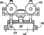
Fig. 7 and Fig. 7 a to 7g provide an embodiment-container 100 of one embodiment of the invention, this container has at least a projection 101 to be " fin-shaped ", and extends to internal space 113 from the sidewall 104 (for sidewall and the base assemblies that fits together) of container 100.In this illustrated embodiment, fin-shaped projection 101 is vertical with fluid intake assembly 110 and fluid outlet assembly 112 basically.Referring to Fig. 7, container 100 is made up of following again: the fluid intake assembly 110 of lid 102, sidewall 104, inner edge 106, inert carrier gas or its mixture flow, allow filler 108 in fluid outlet assembly 112 that the fluid stream that contains precursor flows through and the internal space 113 of precursor material being introduced container 100.In some embodiments, filler 108 can be used as the liquid level vision slit.In these embodiments, filler can comprise: a porthole, inductor block, probe and/or other are used for the instrument that precursor exists in the detection receptacle.
Fig. 7 a to 7c provides the various detailed views of the lid 102 of container 100.Shown in Fig. 7 a and 7b, container 100 has a T-shape pipe 114 to flow into the internal space 113 of container 100 by 110 assemblies with the carrier gases that helps input.In these embodiments, T-shape pipe 114 can reduce the laminar flow of the carrier gases of input, contains the not possibility of the precursor of distillation in the precursor flow stream thereby reduce effusive containing.Lid 102 also can accurately be installed and navigate on the sidewall 116 by using one or more steady braces 111 to help lid 102.
Fig. 7 d provides the detailed side view of the lid 102 that assembles, and this figure has illustrated the inner groovy 116 of lid 102, and this inner groovy is with helping guiding input carrier gases.Fig. 7 d shows that inner groovy 116 comprises at least a portion of upper space 117, and it can guide the carrier gas flow of input away from the precursor that does not have distillation.
In certain embodiments, can add optional separator 118 in container mixes with the fluid stream that contains precursor of output with the precursor that further prevents from not distil.Separator 118 shown in Fig. 7 e to 7g is divided into upper space 117 and lower space 119 two portions to the internal space 113 of container between the sub-body of container and lid.Separator 118 with lid 102 (do not have entrance and exit assembly 110 and 112 and filler 108) and bottom 104 separate.
According to the character of required precursor, may need sometimes to stop in effusive containing in the precursor flow stream and carry solid.In these embodiments, container 10 and 100 may further include the precursor that an optional Stainless Steel Filter plate 120 stops not distillation and enters effusive containing in the precursor flow stream.The aperture of Stainless Steel Filter plate that should be optional can be the 0.1-100 micron.It can be installed in the internal space 113 Anywhere and/or the effusive fluidic that the contains precursor route of flowing through.Fig. 7 f has showed a particular embodiment, and wherein one or more filter plate is installed in 122 li of inner groovies on the separator 118.
In one embodiment, container 10 and 100 also comprises a porthole (not shown in the accompanying drawings) that is used for determining contained material in the internal space 17.The suitable material that constitutes porthole includes enough thermal conductivitys so that steam condenses and the transparent material of minimal deposition on porthole, these materials comprise: for example, and diamond, sapphire, silicon carbide, transparent stupalith etc.
The working temperature of container changes according to the precursor material that is held in the container, is generally about 25 ℃ to about 500 ℃, perhaps from about 100 ℃ to about 300 ℃.The working pressure range of container is: from about 10
-2Torr is to about 1000 torrs, perhaps from about 0.1 torr to about 200 torrs.
Disclosed container using method comprises in a main case of enforcement of the present invention, by filler 26 with precursor material, be incorporated into as solid precursor material in the internal space 17 of container 10, here solid precursor material contacts with one or more projection 34 that extends to internal space 17.The loading level of precursor material preferably reaches with at least a portion Continuous Contact of at least one projection and is no more than the position of the scope of the internal space 17 that comprises this at least one projection.Form pressure sealing or airtight sealing by fastening lid 12, bottom 14 and sidewall 16.Open valve 23 makes inert carrier gas flow into internal space 17 by the pipe 28 that produces vortex.Use a thermal source such as heating tube to make precursor material reach sublimation temperature and form precursor gases.Inert carrier gas combines the fluid stream that formation contains precursor with precursor gases.The fluid flow that contains precursor crosses outlet 24 and placed in- line strainer 30 and 32 arrives the production unit in downstreams, as is used for the reaction chamber of production thin film deposition.
Yet in another embodiment, use the method for container to comprise with precursor material, be incorporated into by filler 108 in the internal space 113 of container 100 as solid precursor material, here precursor material contacts with one or more projection 112 that extends to lower space 119.The loading level of precursor material preferably reaches with at least a portion Continuous Contact of at least one projection 101 and is no more than the position of the scope of the lower space 119 that comprises this at least one projection 101.Form pressure sealing or airtight sealing by fastening lid 102 and main body 104.Make inert carrier gas flow into internal space 113 by open valve 110 by T-shape pipe 114.Use a thermal source such as heating tube to make precursor material reach sublimation temperature and form precursor gases.Inert carrier gas combines the fluid stream that formation contains precursor with precursor gases.The fluid flow that contains precursor is crossed separator 118, optional Stainless Steel Filter plate 120 and fluid outlet 112 arrives the production unit in downstreams, as is used for the reaction chamber of production thin film deposition.
The following examples have been carried out more detailed explanation to container of the present invention and method, but the present invention is not limited to the following examples.
Embodiment
With solid precursor hafnium chloride (HfCl
4) be incorporated herein in the described container and be heated distillation.Flow velocity with 1000sccm is introduced container with carrier gases (nitrogen).The precursor of analog quantity is introduced the quartz container of prior art.The projection that the quartz container of prior art does not contact with precursor material.In Fig. 8 and Fig. 9, use 5 pulse per second (PPS)s, with the flow of 0.5 liter/minute (LPM) precursor materials of 80 grams are heated to 160 ℃ and 180 ℃ respectively.In Figure 10, the data point of rhombus, squares and triangles is represented respectively 500 gram weighting materials is heated to data that following state obtains: 180 ℃, and 5 pulse per second (PPS)s, 0.5LPM; 160 ℃, 2 pulse per second (PPS)s, 1LPM; With 160 ℃, 5 pulse per second (PPS)s, 0.5LPM.
Though with reference to embodiment the present invention is described in detail, obviously, the person skilled in art can make a lot of changes and improvements to the present invention not deviating from the present invention spirit and do not exceed under the situation of the scope of the invention.
Claims (35)
1. container that is used for carrying the fluid stream that contains precursor that comes from solid precursor material, this container comprises:
An internal space, this internal space is divided into upper space and lower space, wherein upper space and lower space fluid communication;
One comprises fluid intake, fluid outlet, optional inlet and the lid of an inner groovy, and wherein at least a portion of upper space is positioned at the inner groovy the inside;
Sidewall between lid and bottom; And
At least one extends to the thermal conductivity projection of lower space, at least one thermal conductivity projection of wherein said solid precursor and this contacts so that improve heat passage to solid precursor, and this at least one thermal conductivity projection is from the extending at the beginning at least of sidewall or bottom and combination thereof.
2. the described container of claim 1 is characterized in that also comprising a thermal source that is connected with interior of the container, and wherein this thermal source is heated to solid precursor the temperature that is enough to form fluid stream.
3. the described container of claim 2 is characterized in that this thermal source comprises a heat conduction cover around this container at least a portion.
4. the described container of claim 2 is characterized in that thermal source comprises a plurality of heating tubes.
5. the described container of claim 4 is characterized in that heating tube embeds the bottom of container.
6. the described container of claim 1 is characterized in that also comprising a strainer that is positioned at the fluid outlet downstream.
7. the described container of claim 6 is characterized in that it also comprises a strainer that is positioned at the fluid outlet upstream.
8. the described container of claim 1 is characterized in that described bottom is demountable.
9. the described container of claim 1 is characterized in that described bottom and sidewall fit together.
10. the described container of claim 1 is characterized in that described bottom comprises at least one thermal conductivity projection.
11. the described container of claim 1 is characterized in that described at least one projection comprises a surface that does not react with contained solid precursor material.
12. the described container of claim 1 is characterized in that described at least one thermal conductivity projection is the cloverleaf configuration.
13. the described container of claim 1 is characterized in that at least one thermal conductivity projection extends from sidewall.
14. the described container of claim 1 is characterized in that described fluid intake comprises that also one makes carrier gas flow enter upper space and the pipe by container side wall.
15. the described container of claim 14 is characterized in that described pipe is a T-shape.
16. the described container of claim 15, at least one end that it is characterized in that forming the T-shape pipe of described fluid intake has the angle.
17. the described container of claim 1 is characterized in that described fluid outlet comprises that also a guiding contains the pipe of the fluid stream flow container of precursor.
18. claim 17 described container is characterized in that described pipe is a T-shape.
19. the described container of claim 18, at least one end that it is characterized in that forming the T-shape pipe of described fluid outlet has the angle.
20. the described container of claim 1 is characterized in that described lid is demountable.
21. a container that is used for carrying the fluid stream that contains precursor that comes from solid precursor material, this container comprises:
An internal space, this internal space is divided into upper space and lower space, wherein upper space and lower space fluid communication;
A lid, this lid comprise that an at least a carrier gases of guiding enters the fluid intake of interior of the container, a fluid outlet and an inner groovy, and wherein at least a portion of upper space is positioned at the inner groovy the inside;
A sidewall, this sidewall has a plurality of thermal conductivity projection and upper limbs that extend to lower space since then, wherein at least a portion of this upper limb contacts with lid, and wherein said solid precursor contacts with described a plurality of thermal conductivity projections so that improve heat passage to solid precursor; With
Separator between lid and sidewall, wherein separator is positioned at the upper limb the inside, and the internal space is divided into upper space and lower space.
22. the described container of claim 21 is characterized in that fluid intake is the T-shape pipe that at least one end has the angle.
23. the described container of claim 21 is characterized in that fluid outlet is the T-shape pipe that at least one end has the angle.
24. the described container of claim 21 is characterized in that it also comprises a thermal source that communicates with the internal space of container, this thermal source is heated to solid precursor the temperature that is enough to form fluid stream.
25. the described container of claim 24 is characterized in that this thermal source comprises a heat conduction cover around this sidewall at least a portion.
26. the described container of claim 21 is characterized in that it also comprises a Stainless Steel Filter plate that contacts with described separator to small part.
27. the described container of claim 21 is characterized in that at least a portion of described thermal conductivity projection comprises a surface that does not react with its solid precursor material that is contacted.
28. the described container of claim 27 is characterized in that at least a portion of described thermal conductivity projection comprises a heat conduction core.
29. a container that is used for carrying the fluid stream that contains precursor that comes from solid precursor material, this container comprises:
An internal space, this internal space is divided into upper space and lower space by a separator, wherein upper space and lower space fluid communication;
A lid, this lid comprise one by T-shape pipe fluid intake, a fluid outlet and inner groovy with the internal space of at least a carrier gases importing container, and wherein at least a portion of upper space is positioned at the inner groovy the inside;
One sidewall that is connected with lid, this sidewall comprise a plurality of thermal conductivity projections that extend to lower space since then, and at least one projection in wherein a plurality of thermal conductivity projections has the surface that does not react with the precursor material that is contacted; And
A thermal source that is connected with the internal space of container, this thermal source are heated to solid precursor the temperature that is enough to form fluid stream.
30. the described container of claim 29, at least one end that it is characterized in that forming the T-shape pipe of described fluid intake has the angle.
31. the described container of claim 29 is characterized in that fluid outlet is the T-shape pipe that at least one end has the angle.
32. a method that is used for carrying the fluid stream that contains precursor of the gas phase that contains solid precursor, this method may further comprise the steps:
The solid precursor introducing is had in the container of internal space, wherein the internal space is divided into lower space and upper space by separator, this container comprises: a bottom, at least one extends to the thermal conductivity projection of lower space, wherein said solid precursor contacts with described at least one thermal conductivity projection, the pressure sealing lid that comprises an inlet and an outlet, the sidewall that lid and bottom are coupled together;
A thermal source that communicates with the internal space of container is provided;
Heat source provides the energy of the gas phase that is enough to form contained solid precursor;
At least a carrier gases is introduced container by inlet, and this carrier gases forms fluid stream to flow into and to combine with the gas phase of described solid precursor from top to bottom and along the direction of container side wall; With
By outlet this fluid is spread the depositing system that is passed to the downstream.
33. the described method of claim 32 is characterized in that this fluid that contains precursor stream also will be by an in-line filter in fluid outlet downstream.
34. the described method of claim 32 is characterized in that carrier gases has the T-shape inlet pipe introducing at angle by at least one end.
35. the described method of claim 32 is characterized in that fluid flow crosses the T-shape outlet pipe transmission that at least one end has the angle.
Applications Claiming Priority (6)
| Application Number | Priority Date | Filing Date | Title |
|---|---|---|---|
| US49618703P | 2003-08-19 | 2003-08-19 | |
| US60/496187 | 2003-08-19 | ||
| US58729504P | 2004-07-12 | 2004-07-12 | |
| US60/587295 | 2004-07-12 | ||
| US10/902,778 US7261118B2 (en) | 2003-08-19 | 2004-08-02 | Method and vessel for the delivery of precursor materials |
| US10/902778 | 2004-08-02 |
Publications (2)
| Publication Number | Publication Date |
|---|---|
| CN1611636A CN1611636A (en) | 2005-05-04 |
| CN100523289C true CN100523289C (en) | 2009-08-05 |
Family
ID=34069125
Family Applications (1)
| Application Number | Title | Priority Date | Filing Date |
|---|---|---|---|
| CNB2004100832841A Active CN100523289C (en) | 2003-08-19 | 2004-08-19 | Method and apparatus for the delivery of precursor materials |
Country Status (10)
| Country | Link |
|---|---|
| US (1) | US7261118B2 (en) |
| EP (1) | EP1508631B1 (en) |
| JP (1) | JP4012181B2 (en) |
| KR (1) | KR100590463B1 (en) |
| CN (1) | CN100523289C (en) |
| AT (1) | ATE466969T1 (en) |
| DE (1) | DE602004026968D1 (en) |
| IL (1) | IL163536A0 (en) |
| SG (2) | SG109618A1 (en) |
| TW (1) | TWI257436B (en) |
Families Citing this family (38)
| Publication number | Priority date | Publication date | Assignee | Title |
|---|---|---|---|---|
| US7601225B2 (en) | 2002-06-17 | 2009-10-13 | Asm International N.V. | System for controlling the sublimation of reactants |
| US7300038B2 (en) * | 2002-07-23 | 2007-11-27 | Advanced Technology Materials, Inc. | Method and apparatus to help promote contact of gas with vaporized material |
| US6921062B2 (en) * | 2002-07-23 | 2005-07-26 | Advanced Technology Materials, Inc. | Vaporizer delivery ampoule |
| US6909839B2 (en) | 2003-07-23 | 2005-06-21 | Advanced Technology Materials, Inc. | Delivery systems for efficient vaporization of precursor source material |
| JP4312555B2 (en) * | 2003-09-18 | 2009-08-12 | 富士フイルム株式会社 | Vacuum deposition crucible and phosphor sheet manufacturing apparatus |
| GB2432371B (en) * | 2005-11-17 | 2011-06-15 | Epichem Ltd | Improved bubbler for the transportation of substances by a carrier gas |
| FI121430B (en) * | 2006-04-28 | 2010-11-15 | Beneq Oy | Hot spring |
| DE102006022534A1 (en) * | 2006-05-15 | 2007-11-22 | Aixtron Ag | Source container one VPE reactor |
| DE102006023046B4 (en) * | 2006-05-17 | 2009-02-05 | Qimonda Ag | Method and starting material for providing a gaseous precursor |
| EP2038456B1 (en) * | 2006-06-09 | 2014-03-05 | Soitec | System and process for high volume deposition of gallium nitride |
| US20080018004A1 (en) * | 2006-06-09 | 2008-01-24 | Air Products And Chemicals, Inc. | High Flow GaCl3 Delivery |
| KR100840783B1 (en) | 2006-08-21 | 2008-06-23 | 삼성전자주식회사 | Method and apparatus for evaporating a precursor, and method of forming a dielectric layer using the method |
| US20080241805A1 (en) * | 2006-08-31 | 2008-10-02 | Q-Track Corporation | System and method for simulated dosimetry using a real time locating system |
| WO2008045972A2 (en) * | 2006-10-10 | 2008-04-17 | Asm America, Inc. | Precursor delivery system |
| US9109287B2 (en) * | 2006-10-19 | 2015-08-18 | Air Products And Chemicals, Inc. | Solid source container with inlet plenum |
| US9481944B2 (en) | 2006-11-22 | 2016-11-01 | Soitec | Gas injectors including a funnel- or wedge-shaped channel for chemical vapor deposition (CVD) systems and CVD systems with the same |
| US9481943B2 (en) * | 2006-11-22 | 2016-11-01 | Soitec | Gallium trichloride injection scheme |
| EP2055804A1 (en) * | 2007-10-29 | 2009-05-06 | Nederlandse Organisatie voor toegepast- natuurwetenschappelijk onderzoek TNO | Method for preparing a deposition from a vapour |
| US8343583B2 (en) * | 2008-07-10 | 2013-01-01 | Asm International N.V. | Method for vaporizing non-gaseous precursor in a fluidized bed |
| CN102597310B (en) | 2009-11-02 | 2015-02-04 | 西格玛-奥吉奇有限责任公司 | Solid precursor delivery assembly and correlation method |
| US9809711B2 (en) | 2012-01-17 | 2017-11-07 | Versum Materials Us, Llc | Catalyst and formulations comprising same for alkoxysilanes hydrolysis reaction in semiconductor process |
| US20130243968A1 (en) | 2012-03-16 | 2013-09-19 | Air Products And Chemicals, Inc. | Catalyst synthesis for organosilane sol-gel reactions |
| US9598766B2 (en) | 2012-05-27 | 2017-03-21 | Air Products And Chemicals, Inc. | Vessel with filter |
| WO2013181521A2 (en) | 2012-05-31 | 2013-12-05 | Advanced Technology Materials, Inc. | Source reagent-based delivery of fluid with high material flux for batch deposition |
| US9347696B2 (en) * | 2012-06-05 | 2016-05-24 | Applied Materials, Inc. | Compact ampoule thermal management system |
| WO2014018740A1 (en) * | 2012-07-25 | 2014-01-30 | William Kimmerle | Chemical precursor bubbler assembly |
| US10170297B2 (en) | 2013-08-22 | 2019-01-01 | Versum Materials Us, Llc | Compositions and methods using same for flowable oxide deposition |
| US10443128B2 (en) * | 2015-04-18 | 2019-10-15 | Versum Materials Us, Llc | Vessel and method for delivery of precursor materials |
| KR101606681B1 (en) * | 2016-01-13 | 2016-03-28 | (주)서일퍼시픽 | Portable cough stimulating device |
| US10876205B2 (en) | 2016-09-30 | 2020-12-29 | Asm Ip Holding B.V. | Reactant vaporizer and related systems and methods |
| US11926894B2 (en) | 2016-09-30 | 2024-03-12 | Asm Ip Holding B.V. | Reactant vaporizer and related systems and methods |
| KR102344996B1 (en) * | 2017-08-18 | 2021-12-30 | 삼성전자주식회사 | Unit for supplying precursor, substrate processing apparatus and method for manufacturing semiconductor device using the same |
| US10597773B2 (en) * | 2017-08-22 | 2020-03-24 | Praxair Technology, Inc. | Antimony-containing materials for ion implantation |
| KR102555932B1 (en) | 2018-06-15 | 2023-07-13 | 버슘머트리얼즈 유에스, 엘엘씨 | Siloxane Compositions and Methods of Using the Compositions to Deposit Silicon-Containing Films |
| JP7376278B2 (en) | 2018-08-16 | 2023-11-08 | エーエスエム・アイピー・ホールディング・ベー・フェー | solid raw material sublimer |
| CN109576675B (en) * | 2019-01-15 | 2021-08-13 | 北京北方华创微电子装备有限公司 | Atomic layer deposition apparatus and method |
| US11624113B2 (en) | 2019-09-13 | 2023-04-11 | Asm Ip Holding B.V. | Heating zone separation for reactant evaporation system |
| US20220275506A1 (en) * | 2021-02-26 | 2022-09-01 | Entegris, Inc. | Solids vaporizer |
Family Cites Families (38)
| Publication number | Priority date | Publication date | Assignee | Title |
|---|---|---|---|---|
| US4723967A (en) * | 1987-04-27 | 1988-02-09 | Advanced Technology Materials, Inc. | Valve block and container for semiconductor source reagent dispensing and/or purification |
| JPH01168331A (en) * | 1987-12-24 | 1989-07-03 | Mitsui Toatsu Chem Inc | Process for saturating organic metallic compound |
| DE3801147A1 (en) * | 1988-01-16 | 1989-07-27 | Philips Patentverwaltung | DEVICE FOR GENERATING A GAS FLOW ENRICHED WITH THE VAPOR OF A LITTLE VOLATILE FABRIC |
| JPH0269389A (en) * | 1988-08-31 | 1990-03-08 | Toyo Stauffer Chem Co | Formation of saturated vapor of solid organometallic compound in vapor growth method |
| US5227340A (en) * | 1990-02-05 | 1993-07-13 | Motorola, Inc. | Process for fabricating semiconductor devices using a solid reactant source |
| JPH0632695A (en) | 1992-07-14 | 1994-02-08 | Fujitsu Ltd | Bubbler |
| US5276585A (en) * | 1992-11-16 | 1994-01-04 | Thermalloy, Inc. | Heat sink mounting apparatus |
| US5381605A (en) * | 1993-01-08 | 1995-01-17 | Photonics Research Incorporated | Method and apparatus for delivering gas |
| US5377429A (en) * | 1993-04-19 | 1995-01-03 | Micron Semiconductor, Inc. | Method and appartus for subliming precursors |
| US5607002A (en) * | 1993-04-28 | 1997-03-04 | Advanced Delivery & Chemical Systems, Inc. | Chemical refill system for high purity chemicals |
| US5707424A (en) * | 1994-10-13 | 1998-01-13 | Advanced Technology Materials, Inc. | Process system with integrated gas storage and delivery unit |
| JP3417751B2 (en) * | 1995-02-13 | 2003-06-16 | 株式会社東芝 | Method for manufacturing semiconductor device |
| US5989305A (en) * | 1995-03-09 | 1999-11-23 | Shin-Etsu Chemical Co., Ltd. | Feeder of a solid organometallic compound |
| US5674574A (en) * | 1996-05-20 | 1997-10-07 | Micron Technology, Inc. | Vapor delivery system for solid precursors and method regarding same |
| US6058012A (en) * | 1996-08-26 | 2000-05-02 | Compaq Computer Corporation | Apparatus, method and system for thermal management of an electronic system having semiconductor devices |
| US6077356A (en) * | 1996-12-17 | 2000-06-20 | Advanced Technology Materials, Inc. | Reagent supply vessel for chemical vapor deposition |
| US6089184A (en) * | 1997-06-11 | 2000-07-18 | Tokyo Electron Limited | CVD apparatus and CVD method |
| US6520218B1 (en) * | 1998-09-03 | 2003-02-18 | Advanced Technology Materials, Inc. | Container chemical guard |
| US6202591B1 (en) * | 1998-11-12 | 2001-03-20 | Flex Products, Inc. | Linear aperture deposition apparatus and coating process |
| JP2000345345A (en) * | 1999-06-04 | 2000-12-12 | Mitsubishi Electric Corp | Cvd device and vaporizer for cvd device |
| US6444038B1 (en) * | 1999-12-27 | 2002-09-03 | Morton International, Inc. | Dual fritted bubbler |
| KR100360494B1 (en) * | 1999-09-21 | 2002-11-13 | 삼성전자 주식회사 | Bubbler |
| US6244331B1 (en) * | 1999-10-22 | 2001-06-12 | Intel Corporation | Heatsink with integrated blower for improved heat transfer |
| GB9929279D0 (en) | 1999-12-11 | 2000-02-02 | Epichem Ltd | An improved method of and apparatus for the delivery of precursors in the vapour phase to a plurality of epitaxial reactor sites |
| DE60106675T2 (en) * | 2000-05-31 | 2005-12-01 | Shipley Co., L.L.C., Marlborough | Evaporator |
| US6837251B1 (en) * | 2000-06-21 | 2005-01-04 | Air Products And Chemicals, Inc. | Multiple contents container assembly for ultrapure solvent purging |
| US6581649B2 (en) * | 2001-07-13 | 2003-06-24 | L'air Liquide - Societe Anonyme A'directiore Et Conseil De Surveillance Pour L'etude Et L'exploitation Des Procedes Georges Claude | Methods and apparatus for delivering high purity liquids with low vapor pressure |
| US7780785B2 (en) * | 2001-10-26 | 2010-08-24 | Applied Materials, Inc. | Gas delivery apparatus for atomic layer deposition |
| US20030111014A1 (en) * | 2001-12-18 | 2003-06-19 | Donatucci Matthew B. | Vaporizer/delivery vessel for volatile/thermally sensitive solid and liquid compounds |
| JP2003318170A (en) | 2002-04-26 | 2003-11-07 | Japan Pionics Co Ltd | Vaporizer |
| JP3822135B2 (en) | 2002-05-13 | 2006-09-13 | 日本パイオニクス株式会社 | Vaporization supply device |
| US7601225B2 (en) | 2002-06-17 | 2009-10-13 | Asm International N.V. | System for controlling the sublimation of reactants |
| US7186385B2 (en) | 2002-07-17 | 2007-03-06 | Applied Materials, Inc. | Apparatus for providing gas to a processing chamber |
| US6921062B2 (en) * | 2002-07-23 | 2005-07-26 | Advanced Technology Materials, Inc. | Vaporizer delivery ampoule |
| US6915592B2 (en) * | 2002-07-29 | 2005-07-12 | Applied Materials, Inc. | Method and apparatus for generating gas to a processing chamber |
| US6797337B2 (en) * | 2002-08-19 | 2004-09-28 | Micron Technology, Inc. | Method for delivering precursors |
| US6740586B1 (en) * | 2002-11-06 | 2004-05-25 | Advanced Technology Materials, Inc. | Vapor delivery system for solid precursors and method of using same |
| US6909839B2 (en) * | 2003-07-23 | 2005-06-21 | Advanced Technology Materials, Inc. | Delivery systems for efficient vaporization of precursor source material |
-
2004
- 2004-08-02 US US10/902,778 patent/US7261118B2/en active Active
- 2004-08-12 IL IL16353604A patent/IL163536A0/en unknown
- 2004-08-13 SG SG200405525A patent/SG109618A1/en unknown
- 2004-08-13 SG SG200700792-5A patent/SG130188A1/en unknown
- 2004-08-16 TW TW93124581A patent/TWI257436B/en active
- 2004-08-17 KR KR1020040064595A patent/KR100590463B1/en active IP Right Grant
- 2004-08-17 EP EP20040019503 patent/EP1508631B1/en active Active
- 2004-08-17 DE DE200460026968 patent/DE602004026968D1/en active Active
- 2004-08-17 AT AT04019503T patent/ATE466969T1/en not_active IP Right Cessation
- 2004-08-19 JP JP2004239630A patent/JP4012181B2/en active Active
- 2004-08-19 CN CNB2004100832841A patent/CN100523289C/en active Active
Also Published As
| Publication number | Publication date |
|---|---|
| KR20050020643A (en) | 2005-03-04 |
| TW200525046A (en) | 2005-08-01 |
| US20050039794A1 (en) | 2005-02-24 |
| SG109618A1 (en) | 2005-03-30 |
| US7261118B2 (en) | 2007-08-28 |
| KR100590463B1 (en) | 2006-06-19 |
| EP1508631A1 (en) | 2005-02-23 |
| ATE466969T1 (en) | 2010-05-15 |
| JP2005101564A (en) | 2005-04-14 |
| TWI257436B (en) | 2006-07-01 |
| DE602004026968D1 (en) | 2010-06-17 |
| JP4012181B2 (en) | 2007-11-21 |
| IL163536A0 (en) | 2005-12-18 |
| SG130188A1 (en) | 2007-03-20 |
| EP1508631B1 (en) | 2010-05-05 |
| CN1611636A (en) | 2005-05-04 |
Similar Documents
| Publication | Publication Date | Title |
|---|---|---|
| CN100523289C (en) | Method and apparatus for the delivery of precursor materials | |
| JP4809313B2 (en) | Container containing inlet plenum and method of dispensing from container | |
| US20170137936A1 (en) | Vessel With Filter | |
| CN103688339B (en) | Reactant delivery system for ALD/CVD technique | |
| US8951478B2 (en) | Ampoule with a thermally conductive coating | |
| JP6228257B2 (en) | Containers and methods for delivery of precursor materials | |
| JPH03112891A (en) | Gas feeder |
Legal Events
| Date | Code | Title | Description |
|---|---|---|---|
| C06 | Publication | ||
| PB01 | Publication | ||
| C10 | Entry into substantive examination | ||
| SE01 | Entry into force of request for substantive examination | ||
| C14 | Grant of patent or utility model | ||
| GR01 | Patent grant | ||
| TR01 | Transfer of patent right | ||
| TR01 | Transfer of patent right |
Effective date of registration: 20170626 Address after: Arizona, USA Patentee after: Versum Materials US, LLC Address before: American Pennsylvania Patentee before: Air Products and Chemicals, Inc. |