CN100509608C - Beverage dispensing appartus and beverage dispensing system - Google Patents
Beverage dispensing appartus and beverage dispensing system Download PDFInfo
- Publication number
- CN100509608C CN100509608C CNB038261332A CN03826133A CN100509608C CN 100509608 C CN100509608 C CN 100509608C CN B038261332 A CNB038261332 A CN B038261332A CN 03826133 A CN03826133 A CN 03826133A CN 100509608 C CN100509608 C CN 100509608C
- Authority
- CN
- China
- Prior art keywords
- liquid
- pipe
- mouth
- beverage dispensing
- dispensing apparatus
- Prior art date
- Legal status (The legal status is an assumption and is not a legal conclusion. Google has not performed a legal analysis and makes no representation as to the accuracy of the status listed.)
- Expired - Fee Related
Links
Images


Classifications
-
- F—MECHANICAL ENGINEERING; LIGHTING; HEATING; WEAPONS; BLASTING
- F16—ENGINEERING ELEMENTS AND UNITS; GENERAL MEASURES FOR PRODUCING AND MAINTAINING EFFECTIVE FUNCTIONING OF MACHINES OR INSTALLATIONS; THERMAL INSULATION IN GENERAL
- F16K—VALVES; TAPS; COCKS; ACTUATING-FLOATS; DEVICES FOR VENTING OR AERATING
- F16K1/00—Lift valves or globe valves, i.e. cut-off apparatus with closure members having at least a component of their opening and closing motion perpendicular to the closing faces
- F16K1/12—Lift valves or globe valves, i.e. cut-off apparatus with closure members having at least a component of their opening and closing motion perpendicular to the closing faces with streamlined valve member around which the fluid flows when the valve is opened
-
- B—PERFORMING OPERATIONS; TRANSPORTING
- B05—SPRAYING OR ATOMISING IN GENERAL; APPLYING FLUENT MATERIALS TO SURFACES, IN GENERAL
- B05B—SPRAYING APPARATUS; ATOMISING APPARATUS; NOZZLES
- B05B1/00—Nozzles, spray heads or other outlets, with or without auxiliary devices such as valves, heating means
- B05B1/26—Nozzles, spray heads or other outlets, with or without auxiliary devices such as valves, heating means with means for mechanically breaking-up or deflecting the jet after discharge, e.g. with fixed deflectors; Breaking-up the discharged liquid or other fluent material by impinging jets
- B05B1/262—Nozzles, spray heads or other outlets, with or without auxiliary devices such as valves, heating means with means for mechanically breaking-up or deflecting the jet after discharge, e.g. with fixed deflectors; Breaking-up the discharged liquid or other fluent material by impinging jets with fixed deflectors
- B05B1/265—Nozzles, spray heads or other outlets, with or without auxiliary devices such as valves, heating means with means for mechanically breaking-up or deflecting the jet after discharge, e.g. with fixed deflectors; Breaking-up the discharged liquid or other fluent material by impinging jets with fixed deflectors the liquid or other fluent material being symmetrically deflected about the axis of the nozzle
-
- B—PERFORMING OPERATIONS; TRANSPORTING
- B05—SPRAYING OR ATOMISING IN GENERAL; APPLYING FLUENT MATERIALS TO SURFACES, IN GENERAL
- B05B—SPRAYING APPARATUS; ATOMISING APPARATUS; NOZZLES
- B05B1/00—Nozzles, spray heads or other outlets, with or without auxiliary devices such as valves, heating means
- B05B1/30—Nozzles, spray heads or other outlets, with or without auxiliary devices such as valves, heating means designed to control volume of flow, e.g. with adjustable passages
- B05B1/3013—Nozzles, spray heads or other outlets, with or without auxiliary devices such as valves, heating means designed to control volume of flow, e.g. with adjustable passages the controlling element being a lift valve
-
- B—PERFORMING OPERATIONS; TRANSPORTING
- B67—OPENING, CLOSING OR CLEANING BOTTLES, JARS OR SIMILAR CONTAINERS; LIQUID HANDLING
- B67D—DISPENSING, DELIVERING OR TRANSFERRING LIQUIDS, NOT OTHERWISE PROVIDED FOR
- B67D1/00—Apparatus or devices for dispensing beverages on draught
- B67D1/08—Details
- B67D1/0857—Cooling arrangements
- B67D1/0858—Cooling arrangements using compression systems
- B67D1/0861—Cooling arrangements using compression systems the evaporator acting through an intermediate heat transfer means
- B67D1/0865—Cooling arrangements using compression systems the evaporator acting through an intermediate heat transfer means by circulating a cooling fluid along beverage supply lines, e.g. pythons
-
- B—PERFORMING OPERATIONS; TRANSPORTING
- B67—OPENING, CLOSING OR CLEANING BOTTLES, JARS OR SIMILAR CONTAINERS; LIQUID HANDLING
- B67D—DISPENSING, DELIVERING OR TRANSFERRING LIQUIDS, NOT OTHERWISE PROVIDED FOR
- B67D1/00—Apparatus or devices for dispensing beverages on draught
- B67D1/08—Details
- B67D1/0872—Aesthetics, advertising
-
- B—PERFORMING OPERATIONS; TRANSPORTING
- B67—OPENING, CLOSING OR CLEANING BOTTLES, JARS OR SIMILAR CONTAINERS; LIQUID HANDLING
- B67D—DISPENSING, DELIVERING OR TRANSFERRING LIQUIDS, NOT OTHERWISE PROVIDED FOR
- B67D1/00—Apparatus or devices for dispensing beverages on draught
- B67D1/08—Details
- B67D1/12—Flow or pressure control devices or systems, e.g. valves, gas pressure control, level control in storage containers
- B67D1/127—Froth control
-
- B—PERFORMING OPERATIONS; TRANSPORTING
- B67—OPENING, CLOSING OR CLEANING BOTTLES, JARS OR SIMILAR CONTAINERS; LIQUID HANDLING
- B67D—DISPENSING, DELIVERING OR TRANSFERRING LIQUIDS, NOT OTHERWISE PROVIDED FOR
- B67D1/00—Apparatus or devices for dispensing beverages on draught
- B67D1/08—Details
- B67D1/12—Flow or pressure control devices or systems, e.g. valves, gas pressure control, level control in storage containers
- B67D1/14—Reducing valves or control taps
- B67D1/1405—Control taps
- B67D1/1411—Means for controlling the build-up of foam in the container to be filled
- B67D1/1422—Means for controlling the build-up of foam in the container to be filled comprising foam avoiding means
-
- B—PERFORMING OPERATIONS; TRANSPORTING
- B67—OPENING, CLOSING OR CLEANING BOTTLES, JARS OR SIMILAR CONTAINERS; LIQUID HANDLING
- B67D—DISPENSING, DELIVERING OR TRANSFERRING LIQUIDS, NOT OTHERWISE PROVIDED FOR
- B67D1/00—Apparatus or devices for dispensing beverages on draught
- B67D1/08—Details
- B67D1/12—Flow or pressure control devices or systems, e.g. valves, gas pressure control, level control in storage containers
- B67D1/14—Reducing valves or control taps
- B67D1/1405—Control taps
- B67D1/145—Control taps comprising a valve shutter movable in a direction perpendicular to the valve seat
- B67D1/1455—Control taps comprising a valve shutter movable in a direction perpendicular to the valve seat the valve shutter being opened in the same direction as the liquid flow
-
- B—PERFORMING OPERATIONS; TRANSPORTING
- B67—OPENING, CLOSING OR CLEANING BOTTLES, JARS OR SIMILAR CONTAINERS; LIQUID HANDLING
- B67D—DISPENSING, DELIVERING OR TRANSFERRING LIQUIDS, NOT OTHERWISE PROVIDED FOR
- B67D1/00—Apparatus or devices for dispensing beverages on draught
- B67D1/08—Details
- B67D1/12—Flow or pressure control devices or systems, e.g. valves, gas pressure control, level control in storage containers
- B67D1/14—Reducing valves or control taps
- B67D1/1405—Control taps
- B67D1/145—Control taps comprising a valve shutter movable in a direction perpendicular to the valve seat
- B67D1/1466—Control taps comprising a valve shutter movable in a direction perpendicular to the valve seat the valve shutter being opened in a direction opposite to the liquid flow
-
- B—PERFORMING OPERATIONS; TRANSPORTING
- B67—OPENING, CLOSING OR CLEANING BOTTLES, JARS OR SIMILAR CONTAINERS; LIQUID HANDLING
- B67D—DISPENSING, DELIVERING OR TRANSFERRING LIQUIDS, NOT OTHERWISE PROVIDED FOR
- B67D2210/00—Indexing scheme relating to aspects and details of apparatus or devices for dispensing beverages on draught or for controlling flow of liquids under gravity from storage containers for dispensing purposes
- B67D2210/00028—Constructional details
- B67D2210/00047—Piping
- B67D2210/00049—Pipes
- B67D2210/00052—Pipes with flow tranquilisers
Abstract
A beverage dispensing device for dispensing pressurized beverages at a high flow rate without producing excessive foaming comprising a streamlined valve assembly and a downward extending nozzle assembly which permits a range of containers to be filled from the bottom.
Description
Technical field
The present invention relates to distribute the device of soda or pressurized beverage, more specifically, relate to the device that is used for high flow velocities distribution soda or pressurized beverage and generation foam minimum.
Background technology
The production of pressurized beverage (for example beer) is to make beverage contain a certain amount of dissolved gas, normally carbon dioxide (CO
2).Although in brewing and sweat, can produce a certain amount of dissolving CO by nature
2, most of commercial winerys can dissolve extra CO in its product
2For commercial winery, add extra CO
2Have two main purposes.The first, from the viewpoint of quality control, all beer that scalable is produced make it to comprise the CO of same amount
2The second, extra CO
2Offer the more bubbling quality of beer, allow the customer feel better comfort and local flavor.
The beer of most main winery productions be included in 10 and 15psi (the every sq m of 68950 and 103425 newton) between dissolving CO
2Because CO
2Atmospheric level much smaller, when beer is exposed in the ambient atmosphere, tend to discharge the CO of some dissolvings
2Because the complicated chemical of beer constitutes, as dissolving CO
2Can produce foam when leaving solution.
Influential other parameter of the foam volume that produces in the beer is comprised temperature and turbulence level.The physical property of liquid shows that fluid temperature is high more, and the capacity of dissolved gas is more little.Like this, beer temperature is high more, and its dissolved gas is just easier to be overflowed from solution, so beer is easier spumes.The disturbance meeting of turbulent flow and other form produces the unexpected zone jumpy of pressure in beer, cause CO2 to overflow from solution with the form of foam.
Although a lot of beer of primary commercial winery production trend towards with bottle and jar pack, a large amount of beer are also packed with container big, that leak free is called keg (keg).Keg is can use once again and the aluminium vessel of can once again, and it is easy to use, and hygiene can store and distribute 15.5 gallons of (58.7 liters) beer usually.Be contained in the beer in the keg, be called barrelled beer, supply bar, public house, nightclub, sports ground, red-letter day and big party usually.
When consumption, need special device for barrelled beer being assigned to open-top receptacle.Beer dispense tap (being called beer tap usually) comprise valve and spout, be used for control and the guiding beer, make it to flow into open-top receptacle.Beer usually can spume from the outflow of tradition tap the time.A reason of this foaming only is because of the CO that is dissolved in the beer
2With the CO in the ambient atmosphere
2Difference of pressure.When beer is exposed in the atmosphere, CO
2Can from beer, discharge naturally.The Another reason that causes foaming is the turbulent feature of beer when the tradition tap distributes.Even distribute carefully, beer also can splash wall of container and bottom and form foam.
Small amount of foam is often wished.There is not the suitable beer of storing usually can make the CO of its dissolving
2Be lost in the atmosphere and can feel flat.Therefore, concerning the customer, a spot of foam means that beer is fresh.In addition, the promoter of beer has illustrated successfully that perfect beer container should have the abundant foam of one deck.And on the other hand, customer and beverage retailer do not want too much foam.Because inject the CO of container
2Foam has replaced liquid beer, and excessive foam can allow the customer dissatisfied, requires another cup through regular meeting.Understood this point, the retailer has only two selections.They can inject part beer in container, etc. the other beer that reinjects after the foam dissipates, this is a time-consuming procedure.Perhaps, they can pour out excessive foam when infusion containers, can waste beer in this process.
Because excessive foam all is a problem to customer and retailer, so the someone attempts designing its installation and the beer dispensing system that can reach best foam volume in assigning process being set.Except in whole allocation process, beer being remained on constant colder temperature, traditional beer dispensing system be designed to enough slowly flow velocity pour out beer, can not cause foam when under this speed, flowing out the beer bump container of tap.
It is per minute one US gallon (3.785 liters) that legacy system is optimised for flow velocity.The flow velocity of even now is fit to a small amount of situations of distributing of great majority, but under many circumstances, if dispense beer quickly keeps best foam volume simultaneously, retailer and customer can be benefited.In busy bar, public house, red-letter day, large-scale party and sports ground, the customer will arrange very long team and drink.In these cases, retailer and client need dispense beer quickly.
Designed than the standard flow rate of the per minute one US gallon beer dispensing system of dispense beer quickly before.A shortcoming of these systems is that it will use accurate electronic control package usually, makes its manufacturing and maintenance all very expensive.In addition, some in these systems are being used memory storage near the tap place, make that device is very big and are difficult to cleaning.In addition, it is very difficult, also very expensive on existing bar desk such device to be installed.
Summary of the invention
The present invention relates to a kind of beverage dispensing apparatus, it can be with than the high a lot of flow velocity dispense pressurised beverage of existing machinery formula faucet device, and can not produce excessive foam.It can be realized with mechanical device fully, makes and maintenance cost thereby reduce.In addition, install when of the present invention and need not use storage device, thereby be convenient to cleaning and reequip top, existing bar desk in distribution locations or near the distribution locations place.
In a preferred embodiment, the present invention includes and be used for the distribution device of dispense pressurised beverage, it comprises: have the mouth of pipe of inner passage, wherein pressurized beverage at least when initial stream pass through from this mouth of pipe with atmospheric conditions; The liquid receiving end, it connects the end fitting as the pressurized beverage distribution system; And liquid distribution point, it is assigned to air environment with pressurized beverage at least when initial, and wherein the cross-sectional area of mouth of pipe inner passage diminishes to liquid distribution point from the liquid receiving end, and it is continuous that the cross-sectional area of inner passage reduces.
In another embodiment, the invention provides a kind of beverage dispensing system, comprising: the container that holds soda; Energy source, it is to the described soda pressurization in the described container; Valve, it communicates with beverages fluid in the described container, and described valve has open position and off position; The mouth of pipe, it has: the liquid receiving end, this liquid receiving end communicates with described valve fluid; The inner passage, when described valve is shown in an open position, the flow through cross-sectional plane of this inner passage of described soda; Liquid distribution point, it has an opening, described soda enters air environment from this opening outflow at least when initial, the described cross-sectional plane of the described inner passage of the wherein said mouth of pipe reduces to described liquid distribution point from the described liquid receiving end of the described mouth of pipe, reducing of the described cross-sectional area of the described inner passage of the described mouth of pipe is continuous, and the soda that the described mouth of pipe is constructed to the feasible described mouth of pipe of flowing through is full of the entire cross section area of the described mouth of pipe basically, and contacts the surface of described inner passage basically constantly from described liquid receiving end to described liquid distribution point.
In another embodiment, the invention provides a kind of beverage dispensing apparatus, it comprises: the device that will be assigned with the beverage introducing that enters described beverage dispensing apparatus; Increase the device of the flow velocity of liquid in device; Reduce the device of the turbulent flow in the flow of liquid; The device of the foam of minimizing from the liquid that described device distributes; Be used for controlling liquid from described device assigned unit; The wherein said device that is used to reduce turbulent flow comprises: the mouth of pipe with inner passage, liquid receiving end and liquid distribution point, the cross-sectional area of the inner passage of the wherein said mouth of pipe reduces to liquid distribution point from the liquid receiving end, and it is continuous that the cross-sectional area of inner passage reduces.
In another embodiment, the invention provides a kind of beverage dispensing apparatus, it is used for when initial beverage being assigned to air environment from beverage dispensing system at least, and it comprises the mouth of pipe, and beverage flows out by this mouth of pipe, and this mouth of pipe has: the inner passage; The liquid receiving end, it connects the end fitting as beverage dispensing system; With the liquid distribution point that distributes beverage, wherein the cross-sectional area of the inner passage of the mouth of pipe reduces to liquid distribution point from the liquid receiving end, and it is continuous that the cross-sectional area of inner passage reduces.
In another embodiment, the invention provides a kind of beverage dispensing apparatus, it is used for when initial beverage being assigned to air environment from beverage dispensing system at least, and it comprises the mouth of pipe, and this mouth of pipe has: the inner passage; The liquid receiving end, it connects the end fitting as beverage dispensing system; With the liquid distribution point that distributes beverage, the cross-sectional plane of the described inner passage of the wherein said mouth of pipe reduces to described liquid distribution point from the described liquid receiving end of the described mouth of pipe, it is continuous that the cross-sectional area of inner passage reduces, and the beverage that the described mouth of pipe is constructed to the feasible described mouth of pipe of flowing through is full of the entire cross section area of the described mouth of pipe basically, and contacts the surface of described inner passage basically constantly from described liquid receiving end to described liquid distribution point.
In another embodiment, the present invention includes: upwardly extending neck, streamline valve door gear and the nozzle device of extending downwards.The global shape and the size of device can allow a series of containers all be poured from the bottom.In addition, nozzle device comprises fleetline flow divert member, and it is used for substantially dispersion liquid stream radially.So, the foam volume that generates in the time of can reducing the high speed dispense beer.
In one embodiment, the level cross-sectionn of the mouth of pipe from mouth of pipe top to the bottom or the liquid distribution point of the mouth of pipe and reducing gradually.The cross-sectional plane of the cross-sectional profiles that preferably, the reduces liquid that by gravity falls when not having this mouth of pipe stream is consistent.The mouth of pipe of this shape guaranteed from the liquid that wherein flows through keep basically with mouth of pipe inwall continue contact.Like this, stoped the gas of mouth of pipe liquid distribution point to make progress bubbling and enter the mouth of pipe.In addition, act on the acceleration that viscous force between the liquid of the mouth of pipe inwall and the mouth of pipe of flowing through is used for offsetting the mouth of pipe liquid that is caused by gravity.
In another embodiment of the present invention, increase to proofread and correct mobile parts at the mouth of pipe, it can be used for reducing the turbulent flow by the liquid stream of the mouth of pipe.Such parts have also increased the amount of surface area of deceleration viscous force effect.
In another embodiment of the present invention, this device can select two kinds of different in flow rate to come dispense beer.In such embodiments, decompression member and optionally guiding liquids be combined as a whole through multichannel valve and this device of decompression member.When the position with valve is configured such that when at first flowing through pressure reducer before liquid is entering quick beverage dispensing apparatus, the dispensing rate of liquid reduces, this speed is the optimum speed of traditional beer dispensing tap preferably.When the position with valve was configured such that liquid is walked around pressure reducer, beverage dispensing apparatus was with flow velocity operation faster fast.
Because fast beverage device can obtain best foam levels simultaneously with traditional beer distribution system two-fold flow velocity dispense beer at least, it also can be used as the novel article person's that attracts the beverage consumption attention.Make the parts of this device by the employing transparent material, thereby allow the customer can see the beverage that flows therein, can give prominence to this attractive force.
In conjunction with the accompanying drawings, with reference to following, be appreciated that the more advantages and the feature of the embodiment of the invention about detailed description of the present invention.
Description of drawings
Fig. 1 is the lateral plan that the member of beverage dispensing system is shown, and it has the schematic sectional view of first embodiment of quick beverage dispensing apparatus.
Fig. 2 is the detailed schematic sectional view of the quick beverage dispensing apparatus of Fig. 1.
Fig. 3 is the perspective illustration of quick beverage dispensing apparatus second embodiment, and wherein the neck device is substituted by the high distributing tower (draft dispensing tower) that draws.
Fig. 4 is the detailed constructed profile of the valve system of valve Fig. 2 when off position.
Fig. 5 is the lateral plan of another embodiment that is used in the streamline valve parts of the valve system among Fig. 2.
Fig. 6 is the lateral plan of another embodiment that is used in the streamline valve parts of the valve system among Fig. 2.
Fig. 7 is the generalized section of the valve system of Fig. 4, and wherein valve is shown in an open position.
Fig. 8 is the transparent view of the streamline valve parts of Fig. 4, shows curvature and the contour shape of valve shoulder towards the surface of liquid.
Fig. 9 is the transversal transparent view of valve neck and valve shoulder.
Figure 10 is the constructed profile of traditional beer dispensing tap.
Figure 11 is the diagram of action of gravity in the liquid that flows out the tradition tap.
Figure 12 shows the constructed profile of another embodiment of nozzle device, and the wherein linear bevelled mouth of pipe is near the mouth of pipe cross-sectional plane parabolic outlines of Fig. 2.
Figure 13 shows the constructed profile of another embodiment of nozzle device, and wherein the cylinder mouth of pipe is near the parabolic outlines of the mouth of pipe cross-sectional plane of Fig. 2.
Figure 14 is the perspective section view of another embodiment of nozzle device, and wherein the mouth of pipe comprises the corrective flow passage of four semicircles.
Figure 15 is the cutaway view that comprises the nozzle device of the mobile correction channel of two semicircles.
Figure 16 is the cutaway view that comprises the nozzle device of the mobile correction channel of six semicircles.
Figure 17 is the cutaway view that comprises the nozzle device of the mobile correction channel of seven semicircles.
Figure 18 is the detail sections scheme drawing of the nozzle device of Fig. 2, wherein shows container and liquid fluid line, the indication flow diverter make liquid flow to.
Figure 19 is the transparent view of the flow diverter of Fig. 2.
Figure 20 is the cutaway view of another embodiment of flow diverter that is used for the nozzle device of Fig. 2.
Figure 21 also is the cutaway view of another embodiment of flow diverter that is used for the nozzle device of Fig. 2.
Figure 22 also is the cutaway view of another embodiment of flow diverter that is used for the nozzle device of Fig. 2.
The constructed profile of a nozzle device of Figure 23, it has the flow diverter of adjusting position in the vertical.
Figure 24 is the constructed profile of the nozzle device of Figure 23, and the flow diverter shown in it moves on to new location.
Figure 25 is the constructed profile that the quick beverage dispensing apparatus of circular cone diffuser is arranged in its neck device.
Figure 26 is the constructed profile that the quick beverage dispensing apparatus of multichannel valve and decompression member is shown.
Figure 27 is the detailed constructed profile of the multichannel valve of Figure 26, and wherein this valve guiding liquids makes it walk around decompression member.
Figure 28 is the detailed constructed profile of the multichannel valve of Figure 26, and wherein this valve guiding liquids before guiding liquids flows to quick beverage dispensing apparatus passes through decompression member.
The specific embodiment
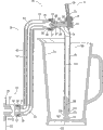
As shown in Figure 1, beverage dispensing apparatus 35 comprises neck device 36, valve system 37 and the nozzle device 38 of extending downwards fast.In a preferred embodiment, neck device 36 is vertical basically.Beverage dispensing apparatus 35 is designed to be connected to traditional pressurized beverage distribution system fast, for example beer dispensing system 39, it comprises: barrel of beer 40 or similar beverage are deposited storage device and are used for beverage is transported to from container or barrel of beer 40 drinking straw 41 of quick beverage dispensing apparatus 35.Shank (shank) 42 is connected to drinking straw 41 with quick beverage dispensing apparatus 35.Keg let-off gear(stand) 43 is connected to barrel of beer 40 with drinking straw 41.Draw distributing tower 44 and support shank 42.
The beer that the main manufacturer of U.S.'s great majority produces is allocated as best the preservation and supply under about 38 Degrees Fahrenheits (3.3 degrees centigrade).Warmer than this optimum temperature as fruit beer, it will discharge too much carbon dioxide (CO in minute timing
2).Than optimum temperature cold, it will keep too much CO in minute timing meeting as fruit beer
2, thereby taste a little less than.Because most systems can not keep precise dose, the scope between 36 and 40 Degrees Fahrenheits (2.2 and 4.4 degrees centigrade) is acceptable normally.Correspondingly, in one embodiment, each member that beer dispensing system 39 of the present invention can cooling system, and these members are remained in the acceptable range of temperatures.
As shown in Figure 1, in a lot of distribution systems, by being trapped in circulating cooling liquid in together the coolant pipe 45 with drinking straw 41, the beer in the drinking straw 41 can keep coolly.Such system utilizes glycol-cooled device 46 and eg pump 47 cooling and circulation ethylene glycols usually.Perhaps, cold air is blown in the conduit that comprises drinking straw 41 as the method that keeps drinking straw 41 coolings by some systems.
For beverage is transferred to quick beverage dispensing system 35 from barrel of beer 40 by whole beer dispensing system 39, the beer in the barrel of beer 40 needs the energy.This energy (normally compresses CO by pressure gas usually
2) provide.As shown in Figure 1, in system, compression CO is housed
2 Jar 48 be connected to barrel of beer 40 by compressed air hose 49.Pressure-regulating device 50 drives the CO of beer by beer dispensing system 39 as regulating
2The device of pressure.Between barrel of beer 40 and quick beverage dispensing apparatus 35, in the bigger system of distance, can use second gas for carrying beer that additonal pressure is provided by drinking straw 41.Be contained in the compressed nitrogen (N in the nitrogen pot 51
2) can be used as this second gas.Nitrogen pot 51 is connected to barrel of beer 40 by compressed air hose 49 independently.Independently pressure-regulating device 50 is as the device of regulating the additonal pressure that compressed nitrogen provides.Some systems can extract nitrogen from air, therefore do not need independently nitrogen pot.Alternatively, in another embodiment, system can use the mechanical pump (not shown) that the energy requirement through system transmissions beer institute is provided, thereby substitutes pressure gas, also uses mechanical pump when perhaps using pressure gas.
Reynolds number (Reynolds number) is to be generally used for the dimensionless parameter that flow of liquid is analyzed.The Reynolds number of flowing through can show laminar flow at the liquid of circular pipe below 2100 or pipe.Reynolds number can show turbulent flow greater than 4000 system.Neither laminar flow neither turbulent flow system can show the feature of excess flow.Reynolds number can calculate by following formula:
Re=Reynolds number wherein
ρ=fluid density
The V=liquid linear velocity
The D=pipe diameter
The viscosity of μ=liquid
Flow of liquid is decision beer one of the several parameters of beer dispensing system 39 flow velocitys of flowing through through the quick pressure decay of beverage dispensing apparatus 35 experience.Flow velocity also is subjected to the diff-H and the compression CO of length, diameter and roughness, barrel of beer 40 and the quick beverage dispensing apparatus 35 of drinking straw 41
2And/or N
2The influence of the energy that provides.Particularly, for the liquid laminar flow that launches fully, flow velocity can be determined according to following formula:
Q=volumetric flowrate wherein
D is the diameter of drinking straw 41
Difference of pressure between Δ p=barrel of beer 40 and the quick beverage dispensing apparatus 35
The beer of μ=distribution or the viscosity of other liquid
The length of the drinking straw 41 that l=beer flows through
The target flow velocity of traditional beer dispensing tap is per minute one US gallon (3.785 liters), and the target flow velocity of beverage dispensing apparatus 35 is twices at least of this speed fast.No matter beer is to flow or flow for three gallons with per minute with one gallon of per minute,, be difficult to become laminar flow completely by drinking straw 41 mobile for the drinking straw 41 of internal diameter less than 1 inch.In these cases, be suitable for following formula:
Wherein
h
L=length of tube is 1 loss in head
F=friction coefficient (function of drinking straw 41 roughnesss and Reynolds number)
The length of l=drinking straw 41
The diameter of D=drinking straw 41
The linear velocity of V=liquid
The g=universal gravitational constant
Therefore, when the diameter of length increase that connects the barrel of beer 41 and the drinking straw 41 of quick beverage dispensing apparatus 35 and drinking straw 41 reduces, must increase and compress CO
2And/or N
2The amount of energy that provides just can overcome the loss in head of additonal pressure.In addition, must increase compression CO
2And/or N
2The amount of energy that provides improves the speed of flow of liquid through drinking straw 41.Preferably, beer dispensing system 39 is designed to the flow velocity that improves beer is transported to shank 42 places, thereby makes quick distribution system 35 that the perfusion of comparing raising with legacy system ability is provided.
Quick beverage dispensing apparatus 35 is located and supported to the neck device 36 of beverage dispensing apparatus 35 fast, and making can be to the multiple size vessels from the glass to the jar in bottom perfusion (bottomfilling).For such container being carried out bottom perfusion, the end 52 of nozzle device 38 and bar desk 53 or directly the distance between thereunder the top of other structure be preferably at least and equate with the height of the largest container that will place.Preferably, need enough spaces jar 54 directly is positioned over below the nozzle device 38.
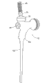
Fig. 2 illustrates in greater detail an embodiment of quick beverage dispensing apparatus 35 of the present invention.Shown in figure 2 among the embodiment, there is screw thread 56 lower end 55 of neck device 36, be connected to standard beer tap shank 42 by standard shank coupling nut 57, gas tight ring 58 and compression washer 59, certainly also other method of attachment be can adopt, flange and quick "cut-off" drvice included but not limited to use with O shape ring.In addition, neck device 36 can for good and all be connected to shank 42 by welding or other method.Usually when the top, bar desk was installed, shank 42 was connected to draw and distributes king-post 60.Connecting pad 61 places between shank 42 and the neck device 36 to guarantee tight seal.In the neck device length that liquid is transported to the neck tube 62 of valve system 37 from shank hole 63.The diameter of neck tube 62 preferably cooperates with the point of connection place of diameter between neck device 36 and shank 42 in shank hole 63.Preferably, the neck tube 62 in neck device 36 lower ends 55 is axially aligning with shank hole 63 the most at the beginning.In the present embodiment, neck tube 62 keeps about 90 degree of vertical front curve in neck device 36.Neck tube 62 bends to the circular arc 64 of about 90 degree in the place near neck device 36 upper ends 65 then.Because the radius of circular arc 64 increases, change relevant turbulent flow with the liquid flow path direction and reduce.Although the circular arc 64 that has than long radius can reduce and the relevant turbulent flow of liquid flow path direction change, this also can cause quick beverage dispensing apparatus 35 bigger in the horizontal throw of drawing between distributing tower 44 and the nozzle device 38.Therefore, the radius of circular arc 64 is preferably enough little, thereby nozzle device 38 can directly be placed on the eduction gear 66 at top, bar desk.In a preferred embodiment, valve system 37 is connected to neck device 36 upper ends 65, makes the liquid neck tube 62 of can flowing through enter valve system 37 and not have seepage.In addition, the neck tube 62 of neck device 36 upper ends 65 internal diameter near valve system 37 time can strengthen, and makes the internal diameter of neck tube 62 cooperate with the internal diameter of valve casing 94 at neck device 36 and valve system bonded assembly place.
Because neck device 36 is exposed in the surrounding environment, the beer that remains in the neck tube 62 at system's stopping period can warm, and this is undesirable.For the residual beer in the neck tube 62 is remained on suitable supply temperature, can be in neck device 36 filling heat insulator 67.Mode as an alternative perhaps as to the replenishing of thermal insulating material 67, can be come glycol cooled neck device 36 (not shown) by coolant pipe 45 is stretched in the neck device 36.
As shown in Figure 3, in another embodiment of the present invention, fast the neck device 36 of beverage dispensing apparatus 35 is substituted by a high distributing tower device 68 that draws, and this is high draws the distributing tower device and comprise and high draw distributing tower 69, draw distributing tower lid 70, draw distributing tower seat 71, mounting screw 72, shank 42 and cylinder insulator 73.In this embodiment, valve system 37 is connected to and is fixed on height and draws shank 42 on the distributing tower 69.Although also can adopt alternate manner, comprise the flange that has O shape ring and quick "cut-off" drvice, valve system 37 can utilize shank coupling nut 57, gas tight ring 58, compression washer 59 and be connected pad 61 and be connected to shank 42.Distance between top, bar desk 53 and the shank 42 makes the end 52 of nozzle device 38 and the height apart from overgauge jar 54 between the top, bar desk 53.In the present embodiment, be not exposed to the neck device in the surrounding environment, and the beer of staying valve system 37 pressure upstream draws in the distributing tower device 68 at height and keeps heat insulation with surrounding environment.In addition, in the present embodiment, the diameter in shank hole 63 increases gradually along its length, make that at one end the diameter in shank hole 63 is identical with the diameter of drinking straw 41, and the internal diameter of the diameter in shank hole 63 and valve casing 94 cooperates with shank 42 point of connection places at valve system 37.
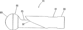
As shown in Figure 4, in one embodiment, valve system 37 comprises valve member 74, handle bar 75, friction ring 76, bonnet washer 77, compression bonnet 78, valve pocket 79, valve seat 80, valve shoulder guide groove 81, outer vent 82 and interior air extractor vent 83.Valve member 74 can comprise valve head 84, valve neck 85, valve shoulder 86 and seat cushion circle 87.Valve neck 85 can be fixed on the valve head 84 by any known way.Preferably, valve neck 85 is fixed on the valve head 84 by engage thread, makes two parts to take apart.Seat cushion circle 87 can place the position between valve head 84 and the valve neck 85.The contour shape of valve head 84, seat cushion circle 87 and valve neck 85 through assembling is fleetlines, disturbs flowing liquid around it with minimum degree ground.Therefore, seat cushion circle 87 is towards the outside face 88 of liquid transition shaping smoothly, and is preferably tangent with the outside face 89 of valve head 84.In addition, seat cushion circle 87 is towards the outer surface smoother ground transition shaping of liquid, and is preferably tangent with valve neck 85.
Fig. 5 and Fig. 6 illustrate other embodiment of valve member 74.In these embodiments, the feature of valve head 84 is spherical in shape basically or oval, and the profile of seat cushion circle 87 outside faces 88 is smoothly transitted into the outside face 89 of valve head 84 usually.In addition, the profile of seat cushion circle 87 outside faces is smoothly transitted into valve neck 85 usually.As shown in Figure 4, the size of valve shoulder 86 can be designed to make it vertically slip into valve shoulder guide groove 81 with a tighter circumference tolerance, thereby makes whole valve member 74 aim in the axial direction with valve pocket 79.The end 90 of handle bar 75 is packed in the valve shoulder groove 91.The ball and cocket joint 92 that is embedded on the handle bar 75 places the ball seat 93 that constitutes valve casing 94 parts.Friction ring 76 and bonnet washer 77 are engaged in around the upper end of ball and cocket joint 92 along circumference.Compression bonnet 78 also can along circumference be engaged in handle bar 75 around, and fix by the screw threads in compression screw thread of bonnet 78 and the valve casing 94.When being screwed to ad-hoc location, compression bonnet 78 heads on friction ring 76 and bonnet washer 77, forms to stop beer to leak out the sealing of valve system 37 by ball seat 93.
Fig. 4 shows the valve system 37 of valve member 74 when detent position.In this position, the proximal thread end 95 of handle bar 75 can be towards angle of valve head 84 inclinations.Because handle bar 75 is around its ball and cocket joint 92 pivoted, in the valve closing position, the end 90 of handle bar 75 tilts to leave an angle from valve head 84, thereby vertically spurs valve member 74, with till valve seat contacts, therefore form the sealing of cutting off flow of liquid up to seat cushion circle 87.In this position, in the valve pocket 79 and the pressure of the liquid by system will than around bar pressure big, CO when preventing not pour out beer in system
2From solution, overflow.Therefore, friction force between fluid pressure in the valve pocket 79 and valve shoulder 86 and the valve shoulder guide groove 81, and the combination of the friction force between valve shoulder groove 91, friction ring 76, bonnet washer 77, compression bonnet 78 and the handle bar 75 is enough to valve member 74 is remained on its detent position.So, no matter the pressure of the liquid upstream of valve member 74 how, does not need spring, lock, actuator or other member that valve member is applied active force valve member 74 is remained on its off position.In addition, when valve member 74 is in detent position, valve shoulder groove 91 forms a passage between outer vent 82 and interior air extractor vent 83, thereby allow air admission mouth of pipe top, when valve member 74 moves on to detent position, can promote quicker like this and discharge any liquid in the nozzle device 38 more completely.
In order to open valve member 74, the thread end 95 of handle bar 75 moves forward along the direction away from valve seat 80 roughly.Because handle bar 75 moves by this way, its centrally-pivoted axle around ball and cocket joint 92 in ball seat 93 rotates, and makes end 90 opposite spins of handle bar 75.The motion of the end 90 of handle bar 75 makes valve member 74 slide in the direction that seat cushion circle 87 is removed from valve seat 80, thereby valve member 74 is placed open position.The power that is acted on the valve head 84 by flowing liquid around it is enough to valve member 74 is remained on its open position in conjunction with friction force between valve shoulder 86 and the valve shoulder guide groove 81 and the friction force between valve shoulder groove 91, friction ring 76, bonnet washer 77, compression bonnet 78 and the handle bar 75, and does not need to be continuously applied active force to handle bar 75 or valve member 74.
Preferably, valve system 37 is designed to stream line pattern as far as possible, to reduce the interference of flow of liquid.Shown in the liquid fluid line among Fig. 7 96, directed flow is through the curved nozzle device 38 that enters common towards the below of the liquid of valve system 37.Therefore, valve member 37 is not only wanted to open and the flowing of stop liquid, and also should reduce the interference of flow of liquid when liquid is imported the mouth of pipe 99 as far as possible.As shown in Figure 8, in order to impel flow of liquid change of direction smoothly, with valve shoulder 86 towards the contour design on the surface 97 of liquid curvature for cooperation valve casing 94 inside faces when valve member 74 is in the open position.Particularly, among the embodiment shown here, the shape of the inside face of the valve casing 94 of close valve shoulder 86 is the part of arc cylinder substantially.That is, valve shoulder 86 surfaces 97 towards liquid are recessed substantially shapes, and have two radiuss of curvature.First radius and the matching of valve casing 94 arc that forms that enters the mouth of pipe 99 by guiding liquids than long radius.Second curvature radius is perpendicular to first radius, and at valve member 37 with the mouth of pipe 99 bonded assemblys are local cooperates with the internal diameter of valve casing 94.Perhaps, can only there be first curvature radius on valve shoulder 86 surfaces 97 towards liquid, and in this case, valve shoulder 86 still can flow into the mouth of pipe 99 with the fleetline form by guiding liquids towards liquid surface 97.In addition, valve shoulder 86 surfaces 97 towards liquid also can be the plane, in this case, the edge on this plane should be concordant with the inside face of valve casing 94 when valve member 74 is positioned at open position, and the degree of this plane inclination can insert the liquid into the mouth of pipe 99 effectively.On the contrary, as shown in figure 10, in traditional beer dispensing tap 98, valve shoulder 86 surfaces 97 towards liquid are tack and vertical substantially plane.In addition, such design can cause liquid to be swerved, shown in liquid fluid line 96.The unexpected changed course of this liquid can cause turbulent flow.
Some liquid of valve pocket 79 flow into necessary process valve neck 85 in nozzle device 38 ways at it because flow through, so the Cross-section Design of valve neck 85 is a stream line pattern, so that liquid is mobile on this direction, as shown in Figure 9.
Except that the embodiment of above-mentioned manual movement of valve parts 74, also will provide valve member opening and closing mobile required energy between the position with automatic or power operation mode.For example, in one embodiment, the available linear actuators that is connected to valve shoulder 86 replaces handle bar 75 with the push-and-pull function of valve member 74 when its off position is shifted to its open position and return.In addition, valve member 74 also can with household electrical appliance in control current the similar mode of screw actuator move by electromagnetic mode.And, gear or other changeover valve travel mechanism also can exercise close and open position between the function of movement of valve parts 74.
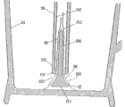
Preferably, the liquid of the valve system 37 of flowing through imports nozzle device 38 immediately, as shown in Figure 2.Preferably, nozzle device 38 comprises the mouth of pipe 99 of downward extension and places liquid dispersion parts or flow diverter 100 near the mouth of pipe 99 lower ends 101.Because gravitational effect, the liquid that the valve system 37 of flowing through enters nozzle device 38 can quicken.Nozzle device 38 satisfies four radical functions.The first, the viscous force between mouth of pipe inside face 102 and the liquid can the slow down speed of liquid stream has been offset the liquid that gravity causes to a certain extent and has been quickened.The second, the shape of design mouth of pipe inside face 102 is so that reduce the chance that air upwards enters system when valve member 74 is in its open position.The solid liquid stream that does not have air can reduce the liquid foam in the nozzle device 38.The 3rd, flow diverter 100 is used for changing the flow direction of the liquid that flows out from nozzle device 38, during the inner surface of container that reduced to pour into when hydraulic shock and the turbulent flow and the foam that cause.Preferably, nozzle device 38 long enoughs make deflector 100 can touch the bottom of the largest container of being poured into, thereby make it possible to from container bottom with near the container bottom perfusion.In a preferred embodiment, the length of nozzle device 38 is approximately 7.62 centimetres (3 inches) to about 38.1 centimetres (15 inches).More preferably, the length of nozzle device 38 is about 10.16 centimetres (4 inches) to about 30.48 centimetres (12 inches).More preferably, the length of nozzle device 38 is that about 20.32 centimetres (8 inches) are to 25.4 centimetres (10 inches).
Figure 11 shows the liquid stream 103 that flows out from tradition tap 98.Lacked the mouth of pipe 99, because action of gravity, the flow velocity when liquid falls of the liquid in the tap 98 increases.This acceleration makes and falls and when tap 98 was more and more far away, the cross-sectional area of liquid stream 103 reduced at liquid.The general shape of its profile is a parabolic shape, and its concrete profile depends on the flow velocity of liquid and the diameter of faucet spout 104.Utilize basic geometry principle to use Bai Nuli formula (Bernoulli ' sequation), can calculate the cross-sectional area of giving the liquid stream 103 of set a distance apart from faucet spout 104.According to Bai Nuli formula (Bernoulli ' s equation):
P wherein
1, p
2Be respectively faucet spout 104 places and apart from the hydraulic pressure of faucet spout 104 a distance
ρ is a fluid density
V
1, V
2Be respectively liquid stream 103 at faucet spout 104 places with apart from the linear velocity of faucet spout 104 a distance
G is the acceleration/accel that gravity causes
z
1And z
2Be meant faucet spout 104 places respectively and apart from the point of faucet spout 104 given distances
Because free-pouring liquid stream 103 is under the bar pressure, so p
1=p
2=0.Z is set
1=0, z
2=h is with V
2RNTO V
0, V
1RNTO V
h, V is provided
hAbout the equation of h, wherein V
hBe that vertical distance is the linear velocity of h place liquid stream 103 below faucet spout 104.
V wherein
0Be liquid stream 103 linear velocities at faucet spout 104 places.
According to following equation, the relation of the linear velocity of the flow velocity of liquid stream 103 and liquid stream 103 and the cross-sectional area of liquid stream 103 is as follows:
Q=A
0V
0
Wherein Q is the flow velocity of liquid
A
0It is the cross-sectional area of faucet spout 104
V
0It is linear velocity at the liquid stream 103 at faucet spout 104 places
Obtain V
0And about V
hEquation in substitute, generate following result:
For the faucet spout 104 of circle, A
0Can be by D
0Express D
0Be the diameter of faucet spout 104:
Carry out again once substituting, obtain and use D
0The V of expression
h:
In addition, because the flow velocity of liquid is constant in compression system not:
Q=A
hV
h
Wherein Q is the volumetric flowrate of liquid
A
hBe liquid stream 103 cross-sectional areas at distance faucet spout 104 distance h places
V
hBe liquid stream 103 linear velocities at distance faucet spout 104 distance h places
According to the above-mentioned A that obtains
hAnd with before the V that tries to achieve
hSubstitute the cross-sectional area V of liquid stream 103
hPromptly can be as the diameter of its vertical distance h, faucet spout 104 and the function of flow rate of liquid apart from faucet spout 104:
Q=V
hA
h
Preferably, as utilize above-mentioned equation to calculate, the shape of cross section of nozzle device 38 with
The shape of cross section of the liquid stream 103 of free-falling body is complementary.In this embodiment, the mouth of pipe 99
Cross-sectional area reduces from the top down gradually.In the preferred embodiment that has used flow diverter,
The mouth of pipe 99 is being widened near its end, and is to hold flow diverter 100, still resulting
The cross-sectional area of concentric ring kept to nozzle device export that 105 place's cross-sectional areas reduce gradually continuity.As shown in the figure, the cross-sectional area of the flow diverter axle 106 of flow diverter increases from the top down gradually, and by using such flow diverter, concentric ring can keep cross-sectional area to reduce gradually.Perhaps, if the cross-sectional plane (not shown) of the mouth of pipe 99 ends reduces gradually, the diameter of the flow diverter axle 106 of flow diverter 100 also can be fixed.Nozzle device 38 with the shape of cross section that mates with the shape of cross section of free-falling body liquid stream 103 can make the liquid that flows through nozzle device 38 remain with mouth of pipe inside face 102 and contact.Like this, the friction force that acts between liquid and the mouth of pipe inside face 102 can make the liquid slow-down.In addition, need only the optimization flow rate of liquid with nozzle device 38, air just can not enter nozzle device 38 with bubble form.
In the optional embodiment of as shown in figure 12 nozzle device 38, have the cross-sectional area that the mouth of pipe 107 of a linear cone reduces gradually near the mouth of pipe 99, the shape of cross section of the shape of cross section of this mouth of pipe 99 and free-pouring liquid stream is complementary.
In another embodiment of as shown in figure 13 nozzle device 38, used the cylinder mouth of pipe 108.In this embodiment, before introducing flow diverter 100, the cross-sectional area of the cylinder mouth of pipe 108 is constant, and in this case, the cross-sectional area that is caused by flow diverter 100 reduces is enough to stop the air admission cylinder mouth of pipe 108 when flow of liquid.Therefore, the liquid distribution point of the cross-sectional area of inner passage from the liquid receiving end of the mouth of pipe to the mouth of pipe diminishes.
In another embodiment as shown in figure 14, nozzle device 38 comprises two or more mobile correction channels 109, is used for reducing the moving radially of liquid of any nozzle device 38, and reduces the turbulent flow of flow of liquid through nozzle device 38.The mouth of pipe 99 preferably is divided at least two path 10s 9, and three to ten path 10s 9 preferably.More preferably with 99 fens four measure-alike path 10s 9 of the mouth of pipe.Figure 15, Figure 16 and Figure 17 show the cross-sectional plane of the various embodiment of the channelled mouth of pipe.
Reynolds number has been indicated the laminar flow or the disturbed flow condition of liquid stream.The Reynolds number of the circular cross section mouth of pipe 99 of the correction channel 109 that do not flow can be expressed as follows:
The Reynolds number of non-circular conduit can be determined by following equation:
Re wherein
hBe based on the Reynolds number of hydraulic diameter.Hydraulic diameter is by D
h=4A/P determines that wherein A is the cross-sectional area of conduit, and P is the girth of conduit.For each measure-alike semicircle wedgy passage 109 in the nozzle device 38:
Wherein D is the internal diameter of the mouth of pipe 99, and n is the number of the semicircle wedgy passage 109 of identical size.Reynolds number with mouth of pipe 99 of path 10 9 generates following ratio with comparing without any the mouth of pipe 99 of the correction channel that flows:
Therefore, the flow through Reynolds number of liquid of the nozzle device 38 that has the correction channel 109 that flows is compared according to coefficient (π)/(π+n) reduce with the nozzle device 38 of the correction channel that do not flow.As point out that the quantity that increases path 10 9 can further reduce the Reynolds number of the liquid of the mouth of pipe 99 of flowing through.In addition, the surface 110 of each mobile correction channel 109 has increased the viscous force that forms between liquid and the surface 110 can act on effective surface area on it, thereby further makes its deceleration during through the mouth of pipe 99 in flow of liquid.
The major cause that produces excess foam when dispense beer is to make beverage collide the bottom of container with fast speed or other turbulent mode.By will turning to gradually from the liquid that nozzle device 38 flows out and disperse, thereby reduce impulsive force between liquid and the container, therefore flow diverter 100 can reduce the generation of foam.Shown in the simulated solution streamline 96 among Figure 18, the liquid of the nozzle device of flowing through 38 is dispersed in around the flow diverter axle 106 equably.When flow of liquid during through flow diverter 100, it flows from roughly downward direction and turns to radial flow gradually.Preferably, the liquid that flows out from nozzle device 38 is with the mode radial dispersion of the 360 average degree that comprise downward vector.Determine that when being the container allocation liquid of various sizes, it is minimum that this mode can make that beverage produces foam.Can also antelabium 111 be set in the mouth of pipe 99 lower ends.Although also can adopt other shape, antelabium 111 is preferably circular, so that improve the flow characteristic of the liquid that flow out from nozzle device outlet 105.
Preferably, flow diverter 100 is swept-out objects.In a preferred embodiment, the near-end 112 of flow diverter 100 is oval domed shape.In this embodiment, circular flow diverter axle 106 broadens gradually towards flow diverter seat 113, thereby turbulent flow is minimum when making fluid diversion.Preferably, the level cross-sectionn of flow diverter 100 on entire longitudinal length is circular, but as long as not serious interference flow of liquid also can be considered other shape.Flow diverter seat 113 also is circular preferably, and is smooth, thereby can make the bottom of Flat bottom container can be against the 113 concordant placements of flow diverter seat.But as long as the outer rim of flow diverter seat 113 bottoms can fully contact the container bottom that will pour into, the bottom of deflector seat 113 also can be recessed slightly surface.The outside face of flow diverter 100 is preferably smooth.
Turbulent flow occurs though the flow diverter 100 of higher broad can reduce when liquid turns to, such flow diverter 100 can cause nozzle device 38 longer broads, therefore difficult with and smaller container be used.Reason needs compacter flow diverter 100 for this reason.Preferably, when measuring between its near-end 112 and the seat 113, flow diverter 100 is between 1.27 centimetres (0.5 inches) to 20.32 centimetres (8 inches).Preferably, when along this linear measure, flow diverter 100 is between 2.54 centimetres (1 inches) to 10.16 centimetres (4 inches).More preferably, when along this linear measure, flow diverter 100 is 5.08 centimetres (2 inches).Preferably, flow diverter seat 113 is between 0.635 centimetre (0.25 inch) to 12.7 centimetres (5 inches) in the observed reading of its widest part.Preferably, flow diverter seat 113 is between 1.27 centimetres (0.5 inches) to 5.08 centimetres (2 inches) in the observed reading of its widest part.Figure 20, Figure 21 and Figure 22 show other embodiment of flow diverter 100.Flow diverter 100 has a lot of other shapes and structure to leave nozzle device 38 and to reduce the foam volume that produces when impacting container at liquid.Flow diverter is back taper preferably.
Preferably, flow diverter 100 is stiff usually, but can be disassembled.Flow diverter 100 can be connected to the mouth of pipe 99 inboards by one or more supporting construction 114.Supporting construction 114 has enough intensity, even there is liquid stream to exist, it is middle that flow diverter 100 is positioned at.In order to reduce the interference to liquid stream, supporting construction 114 is streamline contour preferably, and comprises circular near-end 115, and its some place towards terminal 116 is tapered.Have been found that the wing turbulent flow that supporting construction 114 is caused as shown in figure 19 is minimum.It comprises that in nozzle device 38 flow diverter 100 can not need supporting construction 114 to fix the location under the situation of the correction channel 109 that flows, because can directly be fixed on the surface 110 that forms the correction channel 109 that flows.
Though the height of nozzle device outlet 105 can be the distance of fixing, allow in nozzle device 38, to utilize the fix screw 117 in the mouth of pipe 99 and the specific lengthwise position of countersunk head groove 118 trickle adjustment flow diverters 100 as Figure 23 and an alternative embodiment of the invention shown in Figure 24, unclamp fix screw 117 and can allow flow diverter 100 vertically move.The axle of flow diverter 100 along nozzle device 38 vertically moved, and the height of nozzle device outlet 105 will change.Also can from nozzle device 38, take out fix screw 117 fully, make and flow diverter 100 can be dismantled on nozzle device 38 fully, thereby clean and maintain.
In another embodiment of the present invention, diffuser 121 places the upstream of valve system 37, thereby increases the cross-sectional area of the liquid enter valve system, makes the amount of turbulence minimum.Preferably, diffuser 121 is tapered to its exit end 120 from its larynx end 119.In one embodiment, as shown in figure 25, cone-shaped diffuser 121 places the neck device 36 of quick beverage dispensing apparatus 35.Although it also can comprise radius of curvature, the axis of cone-shaped diffuser 121 is aimed in vertical direction with the neck device 35 of quick beverage dispensing apparatus 35 in the present embodiment.Preferably, the angle of flare of cone-shaped diffuser 121 (angle of measuring between the axis of cone-shaped diffuser 121 and cone-shaped diffuser wall 122) is less.The bigger angle of flare usually can cause turbulent flow to increase, and this is because the cross-sectional area of liquid is forced to increase on short distance.In order to reduce turbulent flow, help simultaneously distributing, the angle of flare of cone-shaped diffuser 121 is preferably less than 25 degree.Preferably, the angle of flare is spent or littler angles and be more preferably 8 less than 12 degree.
Under specific circumstances, need slow down the flow velocity that liquid leaves quick beverage dispensing apparatus 35.In another embodiment of the present invention, as shown in figure 26,, in this system, introduce decompression member 123 and multichannel valve 124 in order selectively to slow down the flow velocity that liquid distributes.Although decompression member 123 can be various ways, preferably, decompression member 123 is made up of one section narrower pipe of diameter.Decompression member 123 is coiled in the neck device 36 of quick beverage dispensing apparatus 35, thereby reduces its requisite space.
The input end 125 of decompression member 123 and mouth 126 are connected to the multichannel valve 124 of the neck seat 127 that places quick beverage dispensing apparatus 35.Shown in the embodiment among Figure 27, a position, multichannel valve 124 is providing unobstructive full port openings (full-port opening) between beverage dispensing apparatus 35 and remaining beer dispensing system 39 fast.The flow through path of multichannel valve 124 of liquid stray arrow head 128 indicating liquids.In this position, liquid stream is walked around decompression member 123 fully, and liquid distributes from quick beverage dispensing apparatus 35 with conventional flow velocity, just as there not being decompression member 123.
As shown in figure 28, in other position, multichannel valve 124 guiding liquids flow through decompression member 123 in its process by quick beverage device 35.In this position, the liquid that enters multichannel valve 124 is directed to the delivery port 129 of valve, and this delivery port is connected to the input end 125 of decompression member 123.Energy from beer dispensing system 39 continued the whole length of moving liquid by decompression member 123 before liquid enters multichannel valve 124 once more by its valve input port 130, this valve input port guiding is passed through quick beverage dispensing apparatus 35 from the liquid of the mouth 126 of decompression member 123.Because enter the pressure decay of the liquid of multichannel valve 124 once more, liquid enters quick beverage dispensing apparatus 35 once more with the flow velocity (the preferably optimum flow rate of traditional beer dispensing tap) that reduces.
Above-mentioned detailed description should be counted as explaining and be not restriction, and it should be understood that the spirit and scope of the present invention should be limited by following claim (comprising all equivalents).Limit.
Claims (56)
1. beverage dispensing apparatus that is used for the dispense pressurised beverage, it comprises the mouth of pipe, and pressurized beverage flows out in the air environment by this mouth of pipe when initial at least, and this mouth of pipe has: the inner passage; The liquid receiving end, it connects the end fitting as the pressurized beverage distribution system; And liquid distribution point, when initial, pressurized beverage is dispensed to air environment at least, wherein the cross-sectional area of the inner passage of the mouth of pipe reduces to liquid distribution point from the liquid receiving end, and it is continuous that the cross-sectional area of inner passage reduces.
2. beverage dispensing apparatus as claimed in claim 1, the length of the wherein said mouth of pipe is at least 7.62 centimetres.
3. beverage dispensing apparatus as claimed in claim 2, the liquid of the described mouth of pipe of wherein flowing through continues to contact with the surface of described inner passage basically.
4. beverage dispensing apparatus as claimed in claim 1, comprise the liquid dispersion parts that have liquid receiving end and liquid dispersion end, described liquid dispersion end stretches out from the described liquid distribution point of the described mouth of pipe, and radial dispersion is from the beverage of the described liquid distribution point outflow of the described mouth of pipe.
5. beverage dispensing apparatus as claimed in claim 4 is supported in the described liquid distribution point of described inner passage of the described mouth of pipe wherein said liquid dispersion part detachable.
6. beverage dispensing apparatus as claimed in claim 4, wherein said liquid dispersion parts also comprise the bar of periphery unanimity and are roughly the liquid dispersion surface of back taper.
7. beverage dispensing apparatus as claimed in claim 6, the liquid dispersion surface of wherein said liquid dispersion parts is stretched out 0.508 centimetre to 3.81 centimetres from the described liquid distribution point of the described mouth of pipe.
8. beverage dispensing apparatus as claimed in claim 7, the liquid dispersion surface of wherein said liquid dispersion parts is stretched out 0.889 centimetre to 1.524 centimetres from the described liquid distribution point of the described mouth of pipe.
9. beverage dispensing apparatus as claimed in claim 8, the liquid dispersion surface of wherein said liquid dispersion parts is stretched out 1.016 centimetres to 1.27 centimetres from the described liquid distribution point of the described mouth of pipe.
10. beverage dispensing apparatus as claimed in claim 5, the liquid dispersion surface of wherein said liquid dispersion parts is adjustable from the distance that the described liquid distribution point of the described mouth of pipe stretches out.
11. beverage dispensing apparatus as claimed in claim 6, wherein said liquid dispersion surface has the inclined-plane that reduces gradually.
12. beverage dispensing apparatus as claimed in claim 11, wherein said liquid dispersion surface makes liquid dispersion from the described mouth of pipe with the certain angle with respect to the described mouth of pipe longitudinal axis.
13. beverage dispensing apparatus as claimed in claim 12, wherein said dispersion surface are approximately perpendicular to the axis of described liquid dispersion parts and make liquid dispersion from the described mouth of pipe.
14. beverage dispensing apparatus as claimed in claim 1, the cross-sectional plane of wherein said inner passage reduce gradually according to the equation of following expression liquid stream cross-sectional area from top to bottom:
Wherein, Q is the volumetric flowrate of liquid,
A
hBe the cross-sectional area of liquid stream at distance faucet spout distance h place,
D
0Be the diameter of faucet spout,
G is the acceleration/accel that gravity causes.
15. beverage dispensing apparatus as claimed in claim 1, the described inner passage of the wherein said mouth of pipe comprises at least two vertical channels.
16. beverage dispensing apparatus as claimed in claim 15, the described inner passage of the wherein said mouth of pipe comprises four vertical channels.
17. a beverage dispensing system comprises:
Hold the container of soda;
Energy source, it is to the described soda pressurization in the described container;
Valve, it communicates with beverages fluid in the described container, and described valve has open position and off position;
The mouth of pipe, it has: the liquid receiving end, this liquid receiving end communicates with described valve fluid; The inner passage, when described valve is shown in an open position, the flow through cross-sectional plane of this inner passage of described soda; Liquid distribution point, it has an opening, described soda enters air environment from this opening outflow at least when initial, the described cross-sectional plane of the described inner passage of the wherein said mouth of pipe reduces to described liquid distribution point from the described liquid receiving end of the described mouth of pipe, reducing of the described cross-sectional area of the described inner passage of the described mouth of pipe is continuous, and the soda that the described mouth of pipe is constructed to the feasible described mouth of pipe of flowing through is full of the entire cross section area of the described mouth of pipe basically, and contacts the surface of described inner passage basically constantly from described liquid receiving end to described liquid distribution point.
18. beverage dispensing system as claimed in claim 17, the diameter of the leading outlet of beginning diameter of this profile wherein, and the flow velocity that limits this profile is the twice at least of the target flow velocity of conventional beer dispense tap.
19. beverage dispensing system as claimed in claim 16 comprises the liquid dispersion parts that have liquid receiving end and liquid distribution point.
20. beverage dispensing system as claimed in claim 19 is supported in the liquid range of distribution of described inner passage of the described mouth of pipe wherein said liquid dispersion part detachable.
21. beverage dispensing system as claimed in claim 20, wherein said liquid dispersion position component is fixed with respect to the described mouth of pipe.
22. beverage dispensing system as claimed in claim 19, wherein said beverage discrete part also comprises the liquid dispersion surface that is roughly back taper.
23. beverage dispensing system as claimed in claim 22, the beverage of wherein said beverage discrete part disperse the surface to stretch out from the liquid dispense aperture of the described mouth of pipe.
24. beverage dispensing system as claimed in claim 23, the liquid dispersion surface of wherein said liquid dispersion parts is stretched out 0.508 centimetre to 3.81 centimetres from the described liquid distribution point of the described mouth of pipe.
25. beverage dispensing system as claimed in claim 22, wherein said liquid dispersion parts are adjustable.
26. beverage dispensing system as claimed in claim 22, wherein said liquid dispersion surface has the inclined-plane that reduces gradually.
27. beverage dispensing system as claimed in claim 26, wherein said liquid dispersion surface makes liquid dispersion from the described mouth of pipe with the certain angle with respect to the described mouth of pipe longitudinal axis.
28. beverage dispensing system as claimed in claim 27, wherein said liquid dispersion surface are approximately perpendicular to the axis of the described mouth of pipe and make liquid dispersion from the described mouth of pipe.
29. beverage dispensing system as claimed in claim 27, wherein said dispersion surface is from described liquid dispersion parts dispersing liquid radially.
30. beverage dispensing system as claimed in claim 16, the wherein said mouth of pipe also comprises at least two vertical channels.
31. beverage dispensing system as claimed in claim 30, wherein said valve comprises valve head, valve rod and valve body.
32. beverage dispensing system as claimed in claim 31, wherein said valve body also comprise the valve shoulder that is offset on the valve rod.
33. beverage dispensing system as claimed in claim 32, the surface of wherein said valve shoulder is consistent with the interior profile of valve casing.
34. beverage dispensing system as claimed in claim 33, the part of wherein said valve shoulder surface and the axis of described valve rod form an acute angle.
35. beverage dispensing system as claimed in claim 34, the surface of wherein said valve shoulder is an indent.
36. a beverage dispensing apparatus, it comprises:
Will be assigned with the device of the beverage introducing that enters described beverage dispensing apparatus;
Increase the device of the flow velocity of liquid in device;
Reduce the device of the turbulent flow in the flow of liquid;
The device of the foam of minimizing from the liquid that described device distributes;
Be used for controlling liquid from described device assigned unit;
The wherein said device that is used to reduce turbulent flow comprises: the mouth of pipe with inner passage, liquid receiving end and liquid distribution point, the cross-sectional area of the inner passage of the wherein said mouth of pipe reduces to liquid distribution point from the liquid receiving end, and it is continuous that the cross-sectional area of inner passage reduces.
37. beverage dispensing apparatus as claimed in claim 36 also comprises the device that reduces described fluid pressure.
38. beverage dispensing apparatus as claimed in claim 37 also comprises the device that cools off the liquid in the described beverage dispensing apparatus.
39. beverage dispensing apparatus as claimed in claim 38 also comprises the flow through device of flow velocity of described beverage dispensing apparatus of controlling liquid optionally.
40. a beverage dispensing apparatus, it is used for when initial beverage being assigned to air environment from beverage dispensing system at least, and it comprises the mouth of pipe, and beverage flows out by this mouth of pipe, and this mouth of pipe has: the inner passage; The liquid receiving end, it connects the end fitting as beverage dispensing system; With the liquid distribution point that distributes beverage, wherein the cross-sectional area of the inner passage of the mouth of pipe reduces to liquid distribution point from the liquid receiving end, and it is continuous that the cross-sectional area of inner passage reduces.
41. beverage dispensing apparatus as claimed in claim 40, the length of the wherein said mouth of pipe is at least 7.62 centimetres.
42. beverage dispensing apparatus as claimed in claim 41, the liquid of the described mouth of pipe of wherein flowing through continues to contact with the surface of described inner passage basically.
43. beverage dispensing apparatus as claimed in claim 40, comprise the liquid dispersion parts that have liquid receiving end and liquid dispersion end, described liquid dispersion end stretches out from the described liquid distribution point of the described mouth of pipe, and radial dispersion is from the beverage of the described liquid distribution point outflow of the described mouth of pipe.
44. beverage dispensing apparatus as claimed in claim 43 is supported in the described liquid distribution point of described inner passage of the described mouth of pipe wherein said liquid dispersion part detachable.
45. beverage dispensing apparatus as claimed in claim 43, wherein said liquid dispersion parts also comprise the bar of periphery basically identical and are roughly the liquid dispersion surface of back taper.
46. beverage dispensing apparatus as claimed in claim 45, the liquid dispersion surface of wherein said liquid dispersion parts is stretched out 0.508 centimetre to 3.81 centimetres from the described liquid distribution point of the described mouth of pipe.
47. beverage dispensing apparatus as claimed in claim 46, the liquid dispersion surface of wherein said liquid dispersion parts is stretched out 0.889 centimetre to 1.524 centimetres from the described liquid distribution point of the described mouth of pipe.
48. beverage dispensing apparatus as claimed in claim 47, the liquid dispersion surface of wherein said liquid dispersion parts is stretched out 1.016 centimetres to 1.27 centimetres from the described liquid distribution point of the described mouth of pipe.
49. beverage dispensing apparatus as claimed in claim 44, the liquid dispersion surface of wherein said liquid dispersion parts is adjustable from the distance that the described liquid distribution point of the described mouth of pipe stretches out.
50. liquid dispersion parts as claimed in claim 45, wherein said liquid dispersion surface has the inclined-plane that reduces gradually.
51. liquid dispersion parts as claimed in claim 50, wherein said liquid dispersion surface makes liquid dispersion from the described mouth of pipe with the certain angle with respect to the described mouth of pipe longitudinal axis.
52. liquid dispersion parts as claimed in claim 51, wherein said dispersion surface are approximately perpendicular to the axis of described liquid dispersion parts and make liquid dispersion from the described mouth of pipe.
53. beverage dispensing apparatus as claimed in claim 40, the cross-sectional plane of wherein said inner passage reduce gradually according to the equation of following expression liquid stream cross-sectional area from top to bottom:
Wherein, Q is the volumetric flowrate of liquid,
A
hBe the cross-sectional area of liquid stream at distance faucet spout distance h place,
D
0Be the diameter of faucet spout,
G is the acceleration/accel that gravity causes.
54. beverage dispensing apparatus as claimed in claim 40, the described inner passage of the wherein said mouth of pipe comprises at least two vertical channels.
55. beverage dispensing apparatus as claimed in claim 54, the described inner passage of the wherein said mouth of pipe comprises four vertical channels.
56. a beverage dispensing apparatus, it is used for when initial beverage being assigned to air environment from beverage dispensing system at least, and it comprises the mouth of pipe, and this mouth of pipe has: the inner passage; The liquid receiving end, it connects the end fitting as beverage dispensing system; With the liquid distribution point that distributes beverage, the cross-sectional plane of the described inner passage of the wherein said mouth of pipe reduces to described liquid distribution point from the described liquid receiving end of the described mouth of pipe, it is continuous that the cross-sectional area of inner passage reduces, and the beverage that the described mouth of pipe is constructed to the feasible described mouth of pipe of flowing through is full of the entire cross section area of the described mouth of pipe basically, and contacts the surface of described inner passage basically constantly from described liquid receiving end to described liquid distribution point.
Applications Claiming Priority (2)
| Application Number | Priority Date | Filing Date | Title |
|---|---|---|---|
| US10/388,907 | 2003-03-13 | ||
| US10/388,907 US7278454B2 (en) | 2003-03-13 | 2003-03-13 | Beverage dispensing apparatus |
Publications (2)
| Publication Number | Publication Date |
|---|---|
| CN1759302A CN1759302A (en) | 2006-04-12 |
| CN100509608C true CN100509608C (en) | 2009-07-08 |
Family
ID=32962155
Family Applications (2)
| Application Number | Title | Priority Date | Filing Date |
|---|---|---|---|
| CNB038261332A Expired - Fee Related CN100509608C (en) | 2003-03-13 | 2003-03-14 | Beverage dispensing appartus and beverage dispensing system |
| CNA038261324A Pending CN1759063A (en) | 2003-03-13 | 2003-08-15 | Beverage dispensing appartus |
Family Applications After (1)
| Application Number | Title | Priority Date | Filing Date |
|---|---|---|---|
| CNA038261324A Pending CN1759063A (en) | 2003-03-13 | 2003-08-15 | Beverage dispensing appartus |
Country Status (15)
| Country | Link |
|---|---|
| US (3) | US7278454B2 (en) |
| EP (4) | EP1625364A4 (en) |
| JP (1) | JP2006513936A (en) |
| CN (2) | CN100509608C (en) |
| AT (1) | ATE395303T1 (en) |
| AU (1) | AU2003224693A1 (en) |
| BR (2) | BR0318181A (en) |
| CA (2) | CA2518643C (en) |
| DK (1) | DK1601608T3 (en) |
| HK (1) | HK1084653A1 (en) |
| MX (2) | MXPA05009716A (en) |
| NZ (1) | NZ541948A (en) |
| PL (2) | PL377214A1 (en) |
| WO (1) | WO2004083789A1 (en) |
| ZA (2) | ZA200506680B (en) |
Families Citing this family (67)
| Publication number | Priority date | Publication date | Assignee | Title |
|---|---|---|---|---|
| US20070151992A1 (en) * | 1999-11-10 | 2007-07-05 | Kevin Carlson | Rapid comestible fluid dispensing apparatus and method |
| US20060032869A1 (en) * | 2003-03-13 | 2006-02-16 | Laminar Technologies, Llc | Beverage dispensing apparatus |
| EP1654072A4 (en) * | 2003-07-14 | 2007-10-03 | Nordson Corp | Apparatus and method for dispensing discrete amounts of viscous material |
| NO324516B1 (en) * | 2004-04-05 | 2007-11-05 | Smartseal As | Dispensing device for reducing the loss of dissolved gas in a liquid |
| US7717294B2 (en) * | 2005-06-20 | 2010-05-18 | South-Tek Systems | Beverage dispensing gas consumption detection with alarm and backup operation |
| ATE428336T1 (en) * | 2005-08-11 | 2009-05-15 | Procter & Gamble | BEVERAGE BREWING APPARATUS WITH MOVABLE SPOUTS |
| NL1030454C2 (en) * | 2005-11-17 | 2007-05-21 | Bravilor Holding Bv | Drain valve for a beverage reservoir and beverage reservoir provided with such a drain valve. |
| AU2006330641A1 (en) | 2005-12-15 | 2007-07-05 | Niagara Dispensing Technologies, Inc. | Beverage dispensing |
| WO2007117327A2 (en) * | 2005-12-15 | 2007-10-18 | Niagara Dispensing Technologies, Inc. | Beverage dispensing |
| EP1969439A2 (en) * | 2005-12-15 | 2008-09-17 | Niagara Dispensing Technologies, Inc. | Beverage dispenser |
| WO2007070884A2 (en) * | 2005-12-15 | 2007-06-21 | Niagara Dispensing Technologies, Inc. | Digital flow control |
| US8066257B2 (en) * | 2006-02-21 | 2011-11-29 | Gennady Arov | Faucet with floating seal member |
| US10631558B2 (en) | 2006-03-06 | 2020-04-28 | The Coca-Cola Company | Methods and apparatuses for making compositions comprising an acid and an acid degradable component and/or compositions comprising a plurality of selectable components |
| US20070245766A1 (en) * | 2006-04-05 | 2007-10-25 | Younkle Matthew C | In-line beverage chilling apparatus |
| US20080142115A1 (en) * | 2006-12-15 | 2008-06-19 | Niagara Dispensing Technologies, Inc. | Beverage dispensing |
| US7823411B2 (en) | 2006-12-15 | 2010-11-02 | Niagara Dispensing Technologies, Inc. | Beverage cooling system |
| US20080202148A1 (en) * | 2007-02-27 | 2008-08-28 | Thomas Gagliano | Beverage cooler |
| CA2631279A1 (en) * | 2007-05-15 | 2008-11-15 | Terence Mcsweeney | Device for use in a dispensing apparatus |
| US8162176B2 (en) | 2007-09-06 | 2012-04-24 | The Coca-Cola Company | Method and apparatuses for providing a selectable beverage |
| RU2008148292A (en) * | 2007-09-18 | 2010-06-20 | Игета Ко., Лтд. (Jp) | BEER FOAMING DEVICE |
| GB2455349A (en) * | 2007-12-07 | 2009-06-10 | Alumasc Dispense Ltd | Beverage dispense tap |
| NL1035761C2 (en) * | 2008-07-28 | 2010-02-05 | Dispensing Technologies Bv | Method and device for metered dispensing of a liquid from a container. |
| US20090192834A1 (en) * | 2008-01-25 | 2009-07-30 | Adams David J | Revenue generation method for monitoring of fluid dispensing system |
| RU2368828C1 (en) * | 2008-04-01 | 2009-09-27 | Закрытое Акционерное Общество "Новосибирскпродмаш" | Triple valve (versions) and device for hand dispensing of foamy and/or carbonated beverages into open containers and its usage |
| NL2001612C2 (en) * | 2008-05-22 | 2009-11-24 | Heineken Supply Chain Bv | Pillar column, tapping device and method for controlling the temperature of the beverage. |
| US9359181B2 (en) | 2008-09-30 | 2016-06-07 | Sig Technology Ag | Filling method and device |
| DE102008049550A1 (en) * | 2008-09-30 | 2010-04-01 | Sig Technology Ag | Method and device for filling |
| GB2474741B (en) * | 2009-08-21 | 2012-03-07 | Schroeder Ind Inc | Beverage dispensing apparatus |
| WO2011069513A1 (en) * | 2009-12-11 | 2011-06-16 | Jens Ksa Holding Aps | Apparatus for dispensing a pressurised liquid |
| ITMI20100254A1 (en) * | 2010-02-19 | 2011-08-20 | Gian Filippo Pagliacci | GUN FOR FUEL DELIVERY PUMPS AND IN PARTICULAR DIESEL OIL WITH REDUCED FOAM FORMATION |
| ITMI20100501A1 (en) * | 2010-03-26 | 2011-09-27 | Gian Filippo Pagliacci | DRAINING TUBE OF A TANK OF A SELF-TANK WITH REDUCED FOAM FORMATION DURING THE DISTRIBUTION OF FUELS AND IN PARTICULAR DIESEL OIL |
| US20120211575A1 (en) * | 2010-08-17 | 2012-08-23 | Hwb, L.L.C. | Beer Tap Diffuser Device |
| US8800817B2 (en) | 2010-12-06 | 2014-08-12 | The Coca-Cola Company | Beverage dispensing device |
| RU2555679C1 (en) * | 2011-06-23 | 2015-07-10 | Витоп Молдинг С.Р.Л. | Connector to actuate drain cocks |
| WO2013126663A1 (en) * | 2012-02-24 | 2013-08-29 | The Coca-Cola Company | Mechanical dispensing system |
| US20140027014A1 (en) | 2012-07-25 | 2014-01-30 | Todd Keeling | System for Reducing Foam at a Tap |
| US9914630B2 (en) | 2013-02-06 | 2018-03-13 | Sapporo Holdings Limited | Tap, server, pouring member, and attachment/detachment tool |
| US9045260B2 (en) | 2013-03-05 | 2015-06-02 | The Coca-Cola Company | Beverage dispensing system |
| US9365407B2 (en) * | 2013-04-10 | 2016-06-14 | Jeffrey M. Grunewald | Device for efficiently transferring a beverage from a dispenser to a container |
| EP2865301A1 (en) * | 2013-10-28 | 2015-04-29 | Nestec S.A. | Beverage dispensing system, method for providing a multi-layered beverage, and ingredients container for use thereof |
| JP6019365B2 (en) | 2013-10-29 | 2016-11-02 | 兵神装備株式会社 | Manufacturing method of discharge system |
| NL2012200C2 (en) | 2014-02-04 | 2015-08-06 | Heineken Supply Chain Bv | Beverage dispensing assembly and tap. |
| EP3021034B1 (en) * | 2014-11-12 | 2019-04-24 | CleanTech Swiss AG | Fitting for liquefied gas bottles and filling method |
| CN105982548A (en) * | 2015-03-04 | 2016-10-05 | 曾文昌 | Coffee machine filter cup structure and coffee machine with coffee machine filter cup |
| US10254771B2 (en) | 2015-04-06 | 2019-04-09 | Pat's Backcountry Beverages, Inc. | System and method for dispensing a beverage |
| US10144630B1 (en) | 2015-04-06 | 2018-12-04 | Steven P. Keeling | Beverage dispensing system |
| US10703620B1 (en) | 2015-04-06 | 2020-07-07 | Steven P. Keeling | Beverage dispensing system |
| US11613455B1 (en) * | 2015-04-15 | 2023-03-28 | Sestra Systems, Inc. | Automated venting of gas/foam from foam on beer detector for carbonated beverages |
| US20160340081A1 (en) | 2015-05-21 | 2016-11-24 | James Cicarelli | Container with laminar flow |
| AU2016341969C9 (en) * | 2015-10-21 | 2021-09-09 | Bobrick Washroom Equipment, Inc. | Conduit for filling a fluid reservoir and methods for filling a fluid reservoir |
| KR102489333B1 (en) * | 2015-11-03 | 2023-01-17 | 코웨이 주식회사 | Structure for preventing discharging residual water of water outlet |
| AU2016357748B2 (en) * | 2015-11-17 | 2021-06-17 | Coravin, Inc. | Beverage extractor for sparkling beverages |
| NZ747200A (en) * | 2016-04-06 | 2023-03-31 | De Bortoli Wines Pty Ltd | Beverage dispenser |
| MX2016011685A (en) * | 2016-09-08 | 2018-03-07 | David Perez Magana | Cup with two compartments, comprising a concentrically arranged tube and valve for combining beverages, and beverage metering mechanism. |
| AU2017364474B2 (en) * | 2016-11-24 | 2020-12-17 | Hoshizaki Lancer Pty Ltd | Clear fount |
| EP3330218A1 (en) * | 2016-11-30 | 2018-06-06 | Anheuser-Busch InBev S.A. | Method for production and dispensing carbonated beer from beer concentrate |
| JP6704338B2 (en) * | 2016-12-16 | 2020-06-03 | サントリーホールディングス株式会社 | Carbonated water cook |
| IT201700105917A1 (en) * | 2017-09-21 | 2019-03-21 | Mario Bonino | Device for heating or cooling a pipe for transporting fluid or semi-fluid products |
| US20190093823A1 (en) * | 2017-09-25 | 2019-03-28 | Steven Richard Scott | Fluid transfer tube |
| KR102630846B1 (en) * | 2018-07-10 | 2024-01-30 | 엘지전자 주식회사 | Decompression device and baverage maker having the same |
| CN110269515A (en) * | 2019-04-22 | 2019-09-24 | 天津苗花生活用品有限公司 | A kind of portable production coffee cup |
| CN110371462B (en) * | 2019-07-12 | 2020-11-27 | 湖州达立智能设备制造有限公司 | Metal can |
| AU2021206264A1 (en) | 2020-01-09 | 2022-09-01 | Sustainable Beverage Technologies Inc. | Systems and methods for metering, mixing, and dispensing liquids, including alcoholic and non-alcoholic beverages |
| US11472691B2 (en) * | 2020-02-21 | 2022-10-18 | Timothy Ohara | Assembly for providing a passageway for a beverage line connected between a beverage vessel contained in a cabinet, and a beverage tap secured to a tabletop accessory |
| NL2026244B1 (en) | 2020-08-10 | 2022-04-13 | Heineken Supply Chain Bv | Dispensing line with in-line regulator valve |
| AU2021201593A1 (en) * | 2020-09-29 | 2022-04-14 | KegLand Holdings Pty Ltd | Beverage tap |
| US20220402664A1 (en) * | 2021-06-17 | 2022-12-22 | Anheuser-Busch Inbev Sa/Nv | Dispense Apparatus |
Family Cites Families (46)
| Publication number | Priority date | Publication date | Assignee | Title |
|---|---|---|---|---|
| BE549933A (en) | ||||
| US1654249A (en) * | 1924-10-13 | 1927-12-27 | Norbert L Lamm | Beverage-dispensing apparatus |
| GB484210A (en) | 1936-11-03 | 1938-05-03 | Webb Lamp Company Ltd | Improvements in anti-splash appliances for taps |
| US2310247A (en) * | 1939-04-06 | 1943-02-09 | Lunken Just Window Corp | Window |
| US2575658A (en) * | 1947-11-21 | 1951-11-20 | Nero Roger Del | Beer faucet |
| US2750079A (en) * | 1955-05-10 | 1956-06-12 | Ernest F Trombley | Drop tube structure |
| US2921143A (en) | 1955-05-31 | 1960-01-12 | Ampex | Multiple channel head assembly |
| US2910247A (en) * | 1955-06-03 | 1959-10-27 | Bastian Blessing Co | Carbonated beverage dispenser |
| US2912143A (en) * | 1958-09-02 | 1959-11-10 | Louis W Woolfolk | Dispensing machine |
| GB898050A (en) | 1959-09-04 | 1962-06-06 | Aitken Of Edinburgh Barfitting | Beer dispenser |
| US3129894A (en) * | 1961-09-21 | 1964-04-21 | Clarence E Schermerhorn | Combined nozzle and guard for faucet spouts |
| US3307751A (en) * | 1966-01-19 | 1967-03-07 | Dole Valve Co | Anti-foaming flow restrictor |
| US3402857A (en) * | 1967-03-28 | 1968-09-24 | American Can Co | Nozzle for milk filler valve |
| US3651991A (en) * | 1970-09-18 | 1972-03-28 | Kenco Products Corp | Dispenser having valves actuated by yoke shaped lever |
| US4111243A (en) * | 1976-06-25 | 1978-09-05 | Consumers Digital Systems Corp. | Beverage dispensing device |
| DE2851182C2 (en) * | 1978-11-27 | 1981-01-29 | Carl Meinhard 4030 Ratingen Becker | Tap for dispensing beverages |
| AU1292483A (en) | 1982-03-30 | 1983-10-06 | Liquipak International B.V. | Valve device |
| US4519427A (en) * | 1983-06-14 | 1985-05-28 | Kirin Beer Kabushiki Kaisha | Device for recovering contents in containers such as beer bottles |
| US4606382A (en) * | 1984-03-12 | 1986-08-19 | Figgie International Inc. | Nozzle assembly for a filling apparatus |
| US4686421A (en) * | 1985-05-30 | 1987-08-11 | Gte Products Corporation | Glow discharge starter and arc discharge lamp containing same |
| GB8717163D0 (en) | 1987-07-21 | 1987-08-26 | Cook B A | Fluid dispenser |
| US4869396A (en) * | 1987-08-24 | 1989-09-26 | Kirin Beer Kabushiki Kaisha | Draught beer dispensing system |
| US5238155A (en) * | 1991-02-11 | 1993-08-24 | Jack W. Kaufman | Foam generating device |
| US5368205A (en) * | 1993-07-19 | 1994-11-29 | Banner Beverage Systems, Inc. | Apparatus for controlling foaming and flowrate in beverage dispensing systems |
| US5607084A (en) * | 1994-10-28 | 1997-03-04 | George; David L. | Locking system for beverage taps |
| US5603363A (en) * | 1995-06-20 | 1997-02-18 | Exel Nelson Engineering Llc | Apparatus for dispensing a carbonated beverage with minimal foaming |
| US5566732A (en) * | 1995-06-20 | 1996-10-22 | Exel Nelson Engineering Llc | Beverage dispenser with a reader for size indica on a serving container |
| EP0958233A1 (en) * | 1995-12-08 | 1999-11-24 | Vassingerod Metalstoberi A/S | Taphane |
| US5794823A (en) * | 1996-07-31 | 1998-08-18 | Stainless One Dispensing Systems | Limited action flow control fluid dispenser |
| US5758698A (en) * | 1996-08-01 | 1998-06-02 | Tetra Laval Holdings & Finance, S.A. | Fill system including a valve assembly and corresponding structure for reducing the mixing of product and air during container filling |
| US6041970A (en) * | 1996-08-30 | 2000-03-28 | Imi Cornelius Inc. | Pre-mix beverage dispensing system and components thereof |
| US5775387A (en) * | 1996-09-10 | 1998-07-07 | Tetra Laval Holdings & Finance, S. A. | Container filling system having fill-pipe with an extended sealing member for reducing mixing of product and air during container filling |
| US5842617A (en) * | 1996-09-13 | 1998-12-01 | Younkle; Matthew C. | Fast tap apparatus for dispensing pressurized beverages |
| US5862996A (en) * | 1997-01-10 | 1999-01-26 | The Procter & Gamble Company | Laminar flow nozzle |
| EP0861801A1 (en) | 1997-02-27 | 1998-09-02 | Whitbread Plc | Beverage dispenser |
| US5996842A (en) * | 1998-06-24 | 1999-12-07 | The Coca-Cola Company | Apparatus and method for dispensing a cool beverage |
| MY132497A (en) * | 1999-03-26 | 2007-10-31 | Carlsberg Tetley Brewing Ltd | Beer dispenser |
| JP3695255B2 (en) * | 1999-10-15 | 2005-09-14 | 三菱自動車工業株式会社 | Vehicle wheel structure |
| WO2001032549A2 (en) * | 1999-11-03 | 2001-05-10 | Dispensing Systems Inc. | Apparatus and method for dispensing a carbonated beverage with minimal/controlled foaming under system pressure |
| US6443335B1 (en) * | 1999-11-10 | 2002-09-03 | Shurflo Pump Manufacturing Company, Inc. | Rapid comestible fluid dispensing apparatus and method employing a diffuser |
| US6234223B1 (en) * | 2000-01-24 | 2001-05-22 | Dispensing Systems, Inc. | Carbonated beverage and ice dispensing system |
| US6234222B1 (en) * | 2000-01-24 | 2001-05-22 | Dispensing Systems, Inc. | Automated container positioning apparatus for a carbonated beverage dispensing system |
| US6276150B1 (en) * | 2000-01-24 | 2001-08-21 | Dispensing Systems, Inc. | Chilling technique for dispensing carbonated beverage |
| US6230767B1 (en) * | 2000-01-24 | 2001-05-15 | Dispensing Systems, Inc. | Valve head for dispensing carbonated beverage |
| US6237652B1 (en) * | 2000-01-25 | 2001-05-29 | Dispensing Systems, Inc. | Pressurized system and method for dispensing carbonated beverage |
| US6401598B1 (en) * | 2001-03-27 | 2002-06-11 | Demetrios Tavlarides | Tap carbonation concentrator |
-
2003
- 2003-03-13 US US10/388,907 patent/US7278454B2/en active Active
- 2003-03-14 EP EP03721376A patent/EP1625364A4/en not_active Withdrawn
- 2003-03-14 AU AU2003224693A patent/AU2003224693A1/en not_active Abandoned
- 2003-03-14 JP JP2004569648A patent/JP2006513936A/en active Pending
- 2003-03-14 MX MXPA05009716A patent/MXPA05009716A/en active IP Right Grant
- 2003-03-14 EP EP07013665A patent/EP1842829A3/en not_active Withdrawn
- 2003-03-14 NZ NZ541948A patent/NZ541948A/en unknown
- 2003-03-14 CA CA002518643A patent/CA2518643C/en not_active Expired - Fee Related
- 2003-03-14 CN CNB038261332A patent/CN100509608C/en not_active Expired - Fee Related
- 2003-03-14 BR BRPI0318181-2A patent/BR0318181A/en not_active IP Right Cessation
- 2003-03-14 PL PL377214A patent/PL377214A1/en unknown
- 2003-03-14 WO PCT/US2003/007972 patent/WO2004083789A1/en active Application Filing
- 2003-08-11 US US10/639,771 patent/US7040359B2/en not_active Expired - Lifetime
- 2003-08-15 AT AT03816397T patent/ATE395303T1/en not_active IP Right Cessation
- 2003-08-15 DK DK03816397T patent/DK1601608T3/en active
- 2003-08-15 EP EP03816397A patent/EP1601608B1/en not_active Expired - Lifetime
- 2003-08-15 PL PL377257A patent/PL377257A1/en not_active Application Discontinuation
- 2003-08-15 BR BRPI0318183-9A patent/BR0318183A/en not_active Application Discontinuation
- 2003-08-15 CN CNA038261324A patent/CN1759063A/en active Pending
- 2003-08-15 EP EP08008830A patent/EP1980526A1/en not_active Withdrawn
- 2003-08-15 CA CA2518713A patent/CA2518713C/en not_active Expired - Fee Related
- 2003-08-15 MX MXPA05009721A patent/MXPA05009721A/en active IP Right Grant
-
2004
- 2004-07-30 US US10/903,828 patent/US20050072487A1/en not_active Abandoned
-
2005
- 2005-08-19 ZA ZA200506680A patent/ZA200506680B/en unknown
- 2005-08-19 ZA ZA200506677A patent/ZA200506677B/en unknown
-
2006
- 2006-06-01 HK HK06106325A patent/HK1084653A1/en not_active IP Right Cessation
Also Published As
| Publication number | Publication date |
|---|---|
| PL377257A1 (en) | 2006-01-23 |
| EP1842829A3 (en) | 2008-01-09 |
| US7278454B2 (en) | 2007-10-09 |
| ZA200506677B (en) | 2006-09-27 |
| CA2518643A1 (en) | 2004-09-30 |
| WO2004083789A1 (en) | 2004-09-30 |
| EP1842829A2 (en) | 2007-10-10 |
| HK1084653A1 (en) | 2006-08-04 |
| EP1601608A1 (en) | 2005-12-07 |
| EP1980526A1 (en) | 2008-10-15 |
| ZA200506680B (en) | 2006-06-28 |
| US20040195393A1 (en) | 2004-10-07 |
| ATE395303T1 (en) | 2008-05-15 |
| PL377214A1 (en) | 2006-01-23 |
| CN1759063A (en) | 2006-04-12 |
| EP1625364A4 (en) | 2006-08-02 |
| MXPA05009716A (en) | 2006-03-09 |
| US20040177893A1 (en) | 2004-09-16 |
| NZ541948A (en) | 2008-03-28 |
| CA2518643C (en) | 2009-06-02 |
| BR0318183A (en) | 2006-03-21 |
| CA2518713C (en) | 2010-03-30 |
| AU2003224693A1 (en) | 2004-10-11 |
| EP1601608B1 (en) | 2008-05-14 |
| US20050072487A1 (en) | 2005-04-07 |
| CN1759302A (en) | 2006-04-12 |
| MXPA05009721A (en) | 2006-03-09 |
| DK1601608T3 (en) | 2008-09-22 |
| EP1625364A1 (en) | 2006-02-15 |
| US7040359B2 (en) | 2006-05-09 |
| JP2006513936A (en) | 2006-04-27 |
| BR0318181A (en) | 2006-03-21 |
| CA2518713A1 (en) | 2004-09-30 |
Similar Documents
| Publication | Publication Date | Title |
|---|---|---|
| CN100509608C (en) | Beverage dispensing appartus and beverage dispensing system | |
| US20120055584A1 (en) | Multiple liquid dispenser | |
| US20060032869A1 (en) | Beverage dispensing apparatus | |
| US5842617A (en) | Fast tap apparatus for dispensing pressurized beverages | |
| US8276792B2 (en) | Dispenser having a conical valve assembly | |
| EP1448472B1 (en) | Beverage dispensing system and device | |
| US11116340B2 (en) | Container with laminar flow | |
| AU2005231653B2 (en) | A dispensing device for reducing loss of dissolved gas in a liquid outflow and a method of using same | |
| RU2266862C2 (en) | Manual device for foamed and/or carbonated beverage pouring | |
| RU2337053C2 (en) | Device for hand dispensing of foamy and/or carbonated beverages "pegas-m" | |
| RU36372U1 (en) | Device for manual filling of foaming and / or carbonated drinks | |
| JP2006513937A (en) | Beverage pourer | |
| CA2468468C (en) | Beverage dispensing system and device | |
| NZ541947A (en) | A nozzle for a beverage dispensing apparatus with an internal passageway having a cross-sectional profile which approximates the profile of free falling liquid | |
| CA2392609A1 (en) | Beverage dispensing tap with rifled nozzle |
Legal Events
| Date | Code | Title | Description |
|---|---|---|---|
| C06 | Publication | ||
| PB01 | Publication | ||
| C10 | Entry into substantive examination | ||
| SE01 | Entry into force of request for substantive examination | ||
| REG | Reference to a national code |
Ref country code: HK Ref legal event code: DE Ref document number: 1090692 Country of ref document: HK |
|
| C14 | Grant of patent or utility model | ||
| GR01 | Patent grant | ||
| C17 | Cessation of patent right | ||
| CF01 | Termination of patent right due to non-payment of annual fee |
Granted publication date: 20090708 Termination date: 20100314 |
|
| REG | Reference to a national code |
Ref country code: HK Ref legal event code: WD Ref document number: 1090692 Country of ref document: HK |